EP4509659A2 - Work machine - Google Patents
Work machine Download PDFInfo
- Publication number
- EP4509659A2 EP4509659A2 EP24191450.6A EP24191450A EP4509659A2 EP 4509659 A2 EP4509659 A2 EP 4509659A2 EP 24191450 A EP24191450 A EP 24191450A EP 4509659 A2 EP4509659 A2 EP 4509659A2
- Authority
- EP
- European Patent Office
- Prior art keywords
- vertical plate
- work machine
- disposed
- hydraulic
- turning
- Prior art date
- Legal status (The legal status is an assumption and is not a legal conclusion. Google has not performed a legal analysis and makes no representation as to the accuracy of the status listed.)
- Pending
Links
Images


Classifications
-
- E—FIXED CONSTRUCTIONS
- E02—HYDRAULIC ENGINEERING; FOUNDATIONS; SOIL SHIFTING
- E02F—DREDGING; SOIL-SHIFTING
- E02F9/00—Component parts of dredgers or soil-shifting machines, not restricted to one of the kinds covered by groups E02F3/00 - E02F7/00
- E02F9/08—Superstructures; Supports for superstructures
- E02F9/10—Supports for movable superstructures mounted on travelling or walking gears or on other superstructures
-
- E—FIXED CONSTRUCTIONS
- E02—HYDRAULIC ENGINEERING; FOUNDATIONS; SOIL SHIFTING
- E02F—DREDGING; SOIL-SHIFTING
- E02F9/00—Component parts of dredgers or soil-shifting machines, not restricted to one of the kinds covered by groups E02F3/00 - E02F7/00
- E02F9/08—Superstructures; Supports for superstructures
- E02F9/0858—Arrangement of component parts installed on superstructures not otherwise provided for, e.g. electric components, fenders, air-conditioning units
-
- E—FIXED CONSTRUCTIONS
- E02—HYDRAULIC ENGINEERING; FOUNDATIONS; SOIL SHIFTING
- E02F—DREDGING; SOIL-SHIFTING
- E02F3/00—Dredgers; Soil-shifting machines
- E02F3/04—Dredgers; Soil-shifting machines mechanically-driven
- E02F3/28—Dredgers; Soil-shifting machines mechanically-driven with digging tools mounted on a dipper- or bucket-arm, i.e. there is either one arm or a pair of arms, e.g. dippers, buckets
-
- E—FIXED CONSTRUCTIONS
- E02—HYDRAULIC ENGINEERING; FOUNDATIONS; SOIL SHIFTING
- E02F—DREDGING; SOIL-SHIFTING
- E02F3/00—Dredgers; Soil-shifting machines
- E02F3/04—Dredgers; Soil-shifting machines mechanically-driven
- E02F3/28—Dredgers; Soil-shifting machines mechanically-driven with digging tools mounted on a dipper- or bucket-arm, i.e. there is either one arm or a pair of arms, e.g. dippers, buckets
- E02F3/30—Dredgers; Soil-shifting machines mechanically-driven with digging tools mounted on a dipper- or bucket-arm, i.e. there is either one arm or a pair of arms, e.g. dippers, buckets with a dipper-arm pivoted on a cantilever beam, i.e. boom
- E02F3/32—Dredgers; Soil-shifting machines mechanically-driven with digging tools mounted on a dipper- or bucket-arm, i.e. there is either one arm or a pair of arms, e.g. dippers, buckets with a dipper-arm pivoted on a cantilever beam, i.e. boom working downwardly and towards the machine, e.g. with backhoes
- E02F3/325—Backhoes of the miniature type
-
- E—FIXED CONSTRUCTIONS
- E02—HYDRAULIC ENGINEERING; FOUNDATIONS; SOIL SHIFTING
- E02F—DREDGING; SOIL-SHIFTING
- E02F3/00—Dredgers; Soil-shifting machines
- E02F3/04—Dredgers; Soil-shifting machines mechanically-driven
- E02F3/28—Dredgers; Soil-shifting machines mechanically-driven with digging tools mounted on a dipper- or bucket-arm, i.e. there is either one arm or a pair of arms, e.g. dippers, buckets
- E02F3/36—Component parts
-
- E—FIXED CONSTRUCTIONS
- E02—HYDRAULIC ENGINEERING; FOUNDATIONS; SOIL SHIFTING
- E02F—DREDGING; SOIL-SHIFTING
- E02F9/00—Component parts of dredgers or soil-shifting machines, not restricted to one of the kinds covered by groups E02F3/00 - E02F7/00
- E02F9/08—Superstructures; Supports for superstructures
- E02F9/10—Supports for movable superstructures mounted on travelling or walking gears or on other superstructures
- E02F9/12—Slewing or traversing gears
- E02F9/121—Turntables, i.e. structure rotatable about 360°
-
- E—FIXED CONSTRUCTIONS
- E02—HYDRAULIC ENGINEERING; FOUNDATIONS; SOIL SHIFTING
- E02F—DREDGING; SOIL-SHIFTING
- E02F9/00—Component parts of dredgers or soil-shifting machines, not restricted to one of the kinds covered by groups E02F3/00 - E02F7/00
- E02F9/20—Drives; Control devices
- E02F9/2058—Electric or electro-mechanical or mechanical control devices of vehicle sub-units
- E02F9/2062—Control of propulsion units
- E02F9/207—Control of propulsion units of the type electric propulsion units, e.g. electric motors or generators
-
- E—FIXED CONSTRUCTIONS
- E02—HYDRAULIC ENGINEERING; FOUNDATIONS; SOIL SHIFTING
- E02F—DREDGING; SOIL-SHIFTING
- E02F9/00—Component parts of dredgers or soil-shifting machines, not restricted to one of the kinds covered by groups E02F3/00 - E02F7/00
- E02F9/20—Drives; Control devices
- E02F9/2058—Electric or electro-mechanical or mechanical control devices of vehicle sub-units
- E02F9/2091—Control of energy storage means for electrical energy, e.g. battery or capacitors
-
- E—FIXED CONSTRUCTIONS
- E02—HYDRAULIC ENGINEERING; FOUNDATIONS; SOIL SHIFTING
- E02F—DREDGING; SOIL-SHIFTING
- E02F9/00—Component parts of dredgers or soil-shifting machines, not restricted to one of the kinds covered by groups E02F3/00 - E02F7/00
- E02F9/20—Drives; Control devices
- E02F9/22—Hydraulic or pneumatic drives
-
- B—PERFORMING OPERATIONS; TRANSPORTING
- B60—VEHICLES IN GENERAL
- B60Y—INDEXING SCHEME RELATING TO ASPECTS CROSS-CUTTING VEHICLE TECHNOLOGY
- B60Y2200/00—Type of vehicle
- B60Y2200/40—Special vehicles
- B60Y2200/41—Construction vehicles, e.g. graders, excavators
- B60Y2200/412—Excavators
Definitions
- the present invention relates to a work machine.
- the turning work vehicle disclosed in Patent Document 1 includes a lower traveling body and an upper turning body provided in such a way as to be turnable above the lower traveling body.
- a swing body supported in a horizontally rotatable manner is provided at a front portion of a turning frame constituting a bottom portion of the upper turning body.
- the swing body supports the work machine in such a way as to be rotatable upward and downward.
- On a bottom plate of the turning frame On a bottom plate of the turning frame, a first vertical plate and a second vertical plate, which are erected in such a way as to be located at intervals on left and right sides and to extend in the front-and-rear direction, are disposed.
- a hydraulic type swing cylinder is provided on the opposite side of the first vertical plate across the second vertical plate, and couples the turning frame and the swing body.
- Patent Document 1 Japanese Unexamined Patent Application Publication No. 2019-218784
- a hydraulic pump that pressure-feeds oil to a hydraulic type actuator such as a swing cylinder may be driven by an electric motor.
- the battery unit for supplying electric power to the electric motor is mounted on the turning frame.
- the battery unit occupies a wide area on the turning frame.
- the battery unit Since the battery unit has a large weight, it is considered to be advantageous to dispose the battery unit closer to the center of the turning frame whose strength is improved by disposing the first vertical plate and the second vertical plate that are described above.
- members such as the electric motor and the hydraulic pump are disposed on a side of the battery unit, and there is a possibility that interference between at least a part of these members and the swing cylinder becomes a problem.
- an object of the present invention is to provide a technique capable of appropriately laying out a hydraulic cylinder in a work machine having a swing function utilizing the hydraulic cylinder.
- An exemplary work machine is a work machine including a turning body in front of which a work device is disposed, and the work machine including: a turning frame constituting a bottom portion of the turning body; a first vertical plate and a second vertical plate that extend from a front side to a rear side on the turning frame and are disposed at intervals on left and right sides; a swing body that is horizontally rotatably supported by the turning frame in front of the first vertical plate and the second vertical plate and that supports the work device; a hydraulic cylinder that is disposed on an outer side of a machine body on a side opposite to the second vertical plate side with respect to the first vertical plate on the turning frame, and that has one end portion coupled to the swing body; and an auxiliary vertical plate that is disposed between the first vertical plate and the hydraulic cylinder on the turning frame and coupled to an other end portion of the hydraulic cylinder.
- the hydraulic cylinder in a work machine having a swing function using a hydraulic cylinder, the hydraulic cylinder can be appropriately laid out.
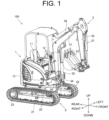
- FIG. 1 is a perspective view illustrating a schematic configuration of a work machine 100 according to an embodiment of the present invention.
- the work machine 100 is specifically a hydraulic excavator.
- the work machine 100 may be, for example, a small-sized hydraulic excavator.
- the work machine according to the present invention is not limited to a hydraulic excavator.
- the present invention is widely applicable to a work machine (turning work machine) including a turning body.
- the work machine 100 includes a turning body 1, a traveling body 2, and a work device 3.
- a front-and-rear direction is defined on the assumption that a side on which the work device 3 is located with respect to the turning body 1 is "front”. Further, a gravity direction perpendicular to the front-and-rear direction is defined as an up-and-down direction, an upstream side in the gravity direction is defined as “up”, and a downstream side in the gravity direction is defined as "down”. A direction perpendicular to the front-and-rear direction and the up-and-down direction is defined as a left-and-right direction, and as viewed from the rear toward the front, a left side is defined as "left” and a right side is defined as "right”.
- a plane parallel to the front-and-rear direction and the left-and-right direction is defined as a horizontal plane, and a plane orthogonal to the horizontal plane is a vertical plane.
- the direction of the turning body 1 is not fixed because the turning body 1 turns around, the expression of the direction is used on the assumption that the turning body 1 is fixed in the direction illustrated in FIG. 1 .
- the directions defined herein are merely names used for explanation, and are not intended to limit the actual positional relationship and directions.
- the turning body 1 is provided in such a way as to be turnable about an axis extending in the up-and-down direction at a central portion thereof.
- the turning body 1 is turnably supported by the traveling body 2 disposed below the turning body 1.
- the turning body 1 is driven to turn by a turning motor, which is not illustrated, constituted as a hydraulic motor.
- the turning body 1 is provided in such a way as to be capable of turning to the right and turning to the left.
- the work device 3 is disposed in front of the turning body 1.
- the work machine 100 includes the turning body 1 in front of which the work device 3 is disposed.
- the turning body 1 is provided with a driver's seat 11 on which an operator who operates the work machine 100 sits. An operator sitting on the driver's seat 11 faces forward and operates various operation devices provided around the driver's seat 11.
- the operation device includes an operation lever 12.
- the driver's seat 11 is supported by a cover (not illustrated) that covers various members disposed inside the turning body 1 (an engine room). Various members disposed inside the turning body 1 will be described below.
- a counterweight 13 is disposed at a rear end portion of the turning body 1.
- the traveling body 2 enables the work machine 100 to travel by itself.
- the traveling body 2 includes a pair of crawlers 22 disposed on the left and right of a traveling body frame 21.
- Each of the crawlers 22 is driven by a traveling motor 23 constituted by a hydraulic motor.
- the traveling body 2 travels straight forward or rearward.
- the forward or backward is determined by a rotational direction of the traveling motor 23.
- the pair of left and right crawlers 22 are independently driven, whereby the traveling body 2 performs a left turn or a right turn.
- traveling body 2 in the present embodiment is a crawler type
- the traveling body is not limited to the crawler type and may be a wheel type or the like.
- a blade for ground leveling work may be provided at a front portion or a rear portion of the traveling body 2.
- the work device 3 includes a boom 31, an arm 32, and a bucket 33.
- the work device 3 performs excavation work of earth and sand or the like by moving the boom 31, the arm 32, and the bucket 33 simultaneously or independently.
- the bucket 33 may be replaced with another work tool such as a breaker, which is utilized when a demolishing work is performed, for example.
- the boom 31, one end portion of which is supported by a boom bracket 34, is rotatable in a vertical plane (rotatable upward and downward).
- the boom bracket 34 is supported by the turning body 1.
- the boom 31 is bent at an intermediate portion and has a V-shape in a side view.
- the boom 31 is rotated by expansion and contraction of a boom cylinder 35 whose one end is coupled to the boom bracket 34 and an other end is coupled to an intermediate portion of the boom 31.
- One end portion of the arm 32 is supported by an other end portion of the boom 31 in such a way as to be rotatable in a vertical plane.
- the arm 32 is rotated by expansion and contraction of an arm cylinder 36 whose one end is coupled to an intermediate portion of the boom 31 and an other end is coupled to one end portion of the arm 32.
- One end portion of the bucket 33 is supported by an other end portion of the arm 32 in such a way as to be rotatable in a vertical plane.
- the bucket 33 is rotated by expansion and contraction of a bucket cylinder 37 whose one end is coupled to the one end portion of the arm 32 and an other end is coupled to the bucket 33.
- the boom 31, the arm 32, and the bucket 33 are each provided in such a way as to be rotatable about an axis (not illustrated) extending in the left-and-right direction.
- the boom bracket 34 is specifically supported by the turning body 1 in such a way as to be rotatable in a horizontal plane (horizontally rotatable). In other words, the boom bracket 34 is rotatable about an axis (not illustrated) extending in the up-and-down direction.
- the boom bracket 34 is rotated counterclockwise or clockwise by expansion and contraction of a swing cylinder 38 whose one end is coupled to the boom bracket 34 and an other end is coupled to the turning body 1. Namely, the action of the swing cylinder 38 allows the work device 3 to swing counterclockwise or clockwise.
- the boom cylinder 35, the arm cylinder 36, the bucket cylinder 37, and the swing cylinder 38 are all hydraulic type cylinders, and are included in a hydraulic actuator of the work machine 100.
- the hydraulic actuator of the work machine 100 also includes the above-described traveling motor 23 and a turning motor (not illustrated). An operator sitting on the driver's seat 11 can perform work using the work device 3 by operating the operation lever 12 described above and thereby controlling the hydraulic actuator.
- FIG. 2 is a perspective view illustrating a schematic configuration of the inside of the turning body 1.
- the turning body 1 includes a turning frame 14 at a bottom portion thereof.
- the work machine 100 includes the turning frame 14 that constitutes the bottom portion of the turning body 1.
- the turning frame 14 is composed of a plate-like member. Various members are mounted on the turning frame 14.
- the work machine 100 includes a battery unit 4, an electric motor 5, a hydraulic pump 6, and a control valve 7.
- the work machine 100 includes the battery unit 4, the electric motor 5, the hydraulic pump 6, and the control valve 7, which are disposed on the turning frame 14.
- FIG. 3 is a schematic plan view of the configuration illustrated in FIG. 2 as viewed from above.
- the turning frame 14 includes a first vertical plate 142 and a second vertical plate 143.
- the work machine 100 includes a first vertical plate 142 and a second vertical plate 143.
- the first vertical plate 142 and the second vertical plate 143 are provided in a plate shape, and are erected at a central portion in the left-and-right direction of an upper surface of the turning frame 14.
- the first vertical plate 142 and the second vertical plate 143 extend from the front to the rear on the turning frame 14, and are disposed at intervals in the left-and-right direction.
- the first vertical plate 142 is disposed on the right side
- the second vertical plate 143 is disposed on the left side.
- the first vertical plate 142 and the second vertical plate 143 have an inclined structure in which the height in the up-and-down direction on the rear side is lower than that on the front side.
- the first vertical plate 142 and the second vertical plate 143 are the same member integrated with the turning frame 14.
- a bracket support portion 144 that supports the boom bracket 34 in a horizontally rotatable manner is provided at a central portion in the left-and-right direction of a front end portion of the turning frame 14. Front end portions of the first vertical plate 142 and the second vertical plate 143 are fixed to the bracket support portion 144.
- the boom bracket 34 that rotatably supports the boom 31 of the work device 3 is an example of the swing body in the present invention. Namely, the work machine 100 includes the swing body 34 that is horizontally rotatably supported by the turning frame 14 in front of the first vertical plate 142 and the second vertical plate 143 and supports the work device 3.
- the battery unit 4 includes at least one battery 41.
- the battery 41 is composed of, for example, a secondary battery such as a lithium ion battery.
- the battery unit 4 includes a plurality of batteries 41.
- the plurality of batteries 41 may be connected in series or in parallel. Further, for example, some of the plurality of batteries 41 may be connected in series, and some of the batteries 41 connected in series may be connected in parallel. In the present embodiment, the number of batteries 41 is four. Two each of the four batteries 41 are connected in series, and the two batteries 41 connected in series are connected in parallel.
- the work machine 100 includes a power feeder (not illustrated) that converts electric power supplied from an AC power supply (such as a commercial power supply) outside the work machine 100 from AC power to DC power.
- the battery unit 4 can be charged by being supplied with electric power from the power feeder. Further, the battery unit 4 can supply electric power to various loads included in the work machine 100, such as the electric motor 5.
- a battery unit support base 145 is provided on the upper surface of the turning frame 14 (see also FIG. 6 , etc.).
- the battery unit support base 145 is the same member integrated with the turning frame 14. In the present embodiment, the battery unit support base 145 is divided into a plurality of parts, but may be formed of a single part.
- the battery unit 4 is supported by the battery unit support base 145 via a vibration isolating member 146.
- the vibration isolating member 146 is constituted by, for example, a rubber member.
- the battery unit 4 supported by the battery unit support base 145 is disposed substantially at the center in the left-right direction of the turning frame 14, and in detail disposed so as to be slightly shifted to the left side from the center. Further, the battery unit 4 supported by the battery unit support base 145 is disposed slightly closer to the rear side from the center in the front-and-rear direction of the turning frame 14. As illustrated in FIG. 3 , the battery unit 4 overlaps with the second vertical plate 143 in a plan view. The battery unit 4 is on the upper side with respect to the second vertical plate 143. As can be seen from the above, the battery unit 4 is disposed closer to the center of the turning frame 14, where the first vertical plate 142 and the second vertical plate 143 are disposed and the strength is thereby increased.
- the electric motor 5 uses electric power of the battery unit 4 as a power supply. Namely, the electric motor 5 is driven by the electric power supplied from the battery unit 4.
- the electric motor 5 is a three phase AC motor whose rotational speed is determined by a rotating magnetic field.
- electric power is supplied from the battery unit 4 to an inverter device, which is not illustrated.
- the inverter device converts DC power supplied from the battery unit 4 into AC power, and supplies the AC power to the electric motor 5.
- a motor support base 147 is provided on the upper surface of the turning frame 14.
- the motor support base 147 is divided into a plurality of parts, but may be formed of a single part.
- the electric motor 5 is supported by the motor support base 147.
- the motor support base 147 is supported by the turning frame 14 via the vibration isolating member 146.
- the electric motor 5 supported by the motor support base 147 is disposed adjacent to one side (the right side in the present embodiment) of the battery unit 4 in the left-right direction. As illustrated in FIG. 3 , the electric motor 5 overlaps the first vertical plate 142 in a plan view. Note that the electric motor 5 is located above with respect to the first vertical plate 142.
- the electric motor 5 which is heavy in weight is disposed at a position relatively close to the central portion of the turning frame 14 in the left-and-right direction, where the first vertical plate 142 and the second vertical plate 143 are disposed and the strength is thereby increased.
- the hydraulic pump 6 is driven by the electric motor 5.
- the hydraulic pump 6 driven by the electric motor 5 pressure-feeds hydraulic oil to the above-described hydraulic actuators (hydraulic cylinders 35 to 38, a hydraulic motor 23, and the like).
- the hydraulic pump 6 is specifically disposed on the right of and adjacent to the electric motor 5.
- the hydraulic pump 6 is coupled to a coupling body 5a provided at a right end of the electric motor 5.
- the motor support base 147 supports the coupling body 5a.
- the hydraulic pump 6 is disposed on an outer side of the machine body on a side opposite to the second vertical plate 143 side (the right side in the present embodiment) with respect to the first vertical plate 142. It is possible to improve the balance of the work machine 100 by disposing a member lighter than a heavy object such as the battery unit 4 on the outer side of the machine body.
- the control valve 7 is interposed between the hydraulic pump 6 and the hydraulic actuators (the hydraulic cylinders 35 to 38, the hydraulic motor 23, and the like).
- the control valve 7 is a control valve that is operated by the operation lever 12 and controls a flow of the hydraulic oil supplied from the hydraulic pump 6 to the hydraulic actuator.
- the control valve 7 specifically controls a flow direction and a flow rate of the hydraulic oil.
- control valve 7 is an assembly of a plurality of hydraulic switching valves.
- the control valve 7 switches the supply and discharge of the hydraulic oil to and from the hydraulic cylinders 35 to 38, the hydraulic motor 23, and the like which are included in the hydraulic actuators, thereby controlling the actions thereof.
- the control valve 7 is disposed on the outer side of the machine body on the side opposite to the first vertical plate 142 side (the left side in the present embodiment) with respect to the second vertical plate 143. It is possible to improve the balance of the work machine 100 by disposing a member lighter than a heavy object such as the battery unit 4 on the outer side of the machine body.
- the swing cylinder 38 is disposed on the outer side of the machine body on the side opposite to the second vertical plate 143 side (the right side in the present embodiment) with respect to the first vertical plate 142, on the turning frame 14.
- one end portion (front end portion) of the swing cylinder 38 is coupled to the boom bracket (swing body) 34.
- the work machine 100 includes a hydraulic cylinder 38 that is disposed on the outer side of the machine body on the side opposite to the second vertical plate 143 side with respect to the first vertical plate 142, on the turning frame 14 and that has one end portion coupled to the swing body 34.
- One end portion of the swing cylinder 38 is coupled to the boom bracket 34 in such a way as to be horizontally rotatable.
- the work machine 100 includes an auxiliary vertical plate 148 disposed between the first vertical plate 142 and the swing cylinder (hydraulic cylinder) 38 on the turning frame 14.
- the auxiliary vertical plate 148 is disposed on the right side of the first vertical plate 142 and on the left side of the swing cylinder 38.
- the auxiliary vertical plate 148 is disposed on the outer side of the machine body with respect to the first vertical plate 142, and is disposed on the inner side of the machine body with respect to the swing cylinder 38.
- the auxiliary vertical plate 148 is provided in a plate shape, and is erected on the upper surface of the turning frame 14.
- the auxiliary vertical plate 148 is the same member integrated with the turning frame 14.
- the auxiliary vertical plate 148 extends from the front to the rear on the turning frame 14.
- the auxiliary vertical plate 148 is disposed so as to be inclined with respect to the first vertical plate 142 similarly extending from the front to the rear.
- the auxiliary vertical plate 148 separates from the first vertical plate 142 to the outer side of the machine body (to the right side in the present embodiment) as it goes from the front to the rear.
- the front side of the auxiliary vertical plate 148 is bent toward the inner side of the machine body (left side) and is directed to the first vertical plate 142.
- a front end portion of the auxiliary vertical plate 148 is connected to the first vertical plate 142.
- the strength of the auxiliary vertical plate 148 can be increased.
- the auxiliary vertical plate 148 is coupled to an other end portion (rear end portion) of the swing cylinder (hydraulic cylinder) 38.
- an other end portion of the swing cylinder 38 is supported by the auxiliary vertical plate 148.
- an other end portion of the swing cylinder 38 is coupled to the auxiliary vertical plate 148 in such a way as to be horizontally rotatable. With such a configuration, the swing cylinder 38 can be supported further on the outer side of the machine body from the auxiliary vertical plate 148 disposed on the outer side of the machine body than the first vertical plate 142. Therefore, the swing cylinder 38 can be easily disposed on the turning frame 14 while avoiding interference with other devices.
- the electric motor 5 is disposed at a position overlapping the first vertical plate 142 in a plan view.
- the swing cylinder 38 can be disposed in such a way as to avoid interference with the electric motor 5.
- the hydraulic pump 6 overlaps the auxiliary vertical plate 148 in a plan view.
- the hydraulic pump 6 is on the upper side with respect to the auxiliary vertical plate 148.
- the hydraulic pump 6 is smaller in size than the electric motor 5, and further, s not directly supported by the turning frame 14.
- FIG. 4 is a side view illustrating a schematic relationship between the auxiliary vertical plate 148, and the swing cylinder 38 and the first vertical plate 142.
- FIG. 4 is a diagram of the turning frame 14 as viewed from the right side.
- the auxiliary vertical plate 148 includes a coupling portion 148a having a coupling structure 1481 for coupling an other end portion (rear end portion) of the swing cylinder (hydraulic cylinder) 38.
- the auxiliary vertical plate 148 includes the coupling portion 148a at its rear end portion.
- the coupling structure 1481 includes an upper plate-like body 1481a and a lower plate-like body 1481b disposed below with respect to the upper plate-like body 1481a.
- the upper plate-like body 1481a and the lower plate-like body 1481b protrude from the coupling portion 148a (auxiliary vertical plate 148) to the outer side of the machine body.
- the upper plate-like body 1481a and the lower plate-like body 1481b protrude rightward from the right side surface of the coupling portion 148a and extend in the horizontal direction.
- the upper plate-like body 1481a and the lower plate-like body 1481b are disposed at an interval in the up-and-down direction.
- a rear end portion 38a of the swing cylinder 38 is disposed between the upper plate-like body 1481a and the lower plate-like body 1481b in the up-and-down direction.
- the rear end portion 38a of the swing cylinder 38 is coupled to the upper plate-like body 1481a and the lower plate-like body 1481b via a pin member 149, which penetrates the plate-like bodies in the up-and-down direction, in such a way as to be horizontally rotatable.
- the coupling portion 148a protrudes upward with respect to the first vertical plate 142.
- the coupling portion 148a that couples an other end portion (rear end portion) of the swing cylinder 38 is likely to increase in height in the up-and-down direction because the coupling structure 1481 is provided. Therefore, if a coupling portion having a coupling structure is provided on the first vertical plate 142 existing inside the machine body, interference with the electric motor 5 or the like becomes a problem.
- the coupling portion 148a is provided on the auxiliary vertical plate 148 disposed on the outer side of the machine body than the first vertical plate 142. Therefore, the swing cylinder 38 can be disposed on the turning frame 14 while avoiding interference with large-sized equipment such as the electric motor 5 disposed on the inner side of the machine body.
- the swing cylinder (hydraulic cylinder) 38 is disposed in front of the hydraulic pump 6.
- the swing cylinder 38 can be disposed in such a way as to avoid the electric motor 5 and the battery unit 4 which are disposed on the inner side of the machine body (the left side in the present embodiment) than the hydraulic pump 6.
- FIGS. 5 and 6 are perspective views illustrating a schematic relationship between the swing cylinder 38 and the hydraulic oil tank 9 on the turning frame 14.
- FIG. 5 is a view as seen obliquely from the forward left.
- FIG. 6 is a view as seen obliquely from the rearward left.
- the hydraulic oil tank 9 is disposed in front of the hydraulic pump 6.
- the hydraulic oil tank 9 is a tank that stores the hydraulic oil discharged by the hydraulic pump 6.
- the work machine 100 includes a hydraulic oil tank 9 that stores the hydraulic oil discharged by the hydraulic pump 6, in front of the hydraulic pump 6.
- the hydraulic oil in the hydraulic oil tank 9 is sent to the control valve 7 by driving the hydraulic pump 6.
- the hydraulic oil sent to the control valve 7 is sent to the hydraulic actuators (the hydraulic cylinders 35 to 38, the hydraulic motor 23, and the like) under the control of the control valve 7.
- the hydraulic oil sent to the control valve 7 a portion of the hydraulic oil that is not sent to the hydraulic actuator, is returned to the hydraulic oil tank 9.
- the hydraulic oil sent to the hydraulic actuator is returned from the hydraulic actuator to the hydraulic oil tank 9 via an oil cooler that is not illustrated.
- the swing cylinder (hydraulic cylinder) 38 passes through a notch portion 91 provided in the hydraulic oil tank 9.
- the notch portion 91 is specifically provided in a lower portion of the hydraulic oil tank 9.
- the notch portion 91 is formed by positioning a left side wall to the right and positioning a bottom wall upward in a part of the lower side of the hydraulic oil tank 9.
- the swing cylinder (hydraulic cylinder) 38 is disposed between the auxiliary vertical plate 148 and a side wall 9a of the part of the hydraulic oil tank 9 where the notch portion 91 is provided.
- the side wall 9a corresponds to the left side wall in the lower portion of the hydraulic oil tank 9, and is positioned on the outer side (right side) of the machine body with respect to the auxiliary vertical plate 148.
- the swing cylinder 38 is disposed between the right surface of the auxiliary vertical plate 148 and the side wall 9a in the left-and-right direction.
- the auxiliary vertical plate 148 supports a bottom wall 9b of the part of the hydraulic oil tank 9 where the notch portion 91 is provided.
- the auxiliary vertical plate 148 supports a left end portion of the bottom wall 9b.
- the auxiliary vertical plate 148 can be provided with not only a function of supporting the swing cylinder 38 but also a function of supporting the hydraulic oil tank 9. Namely, with such a configuration, the number of elements (support members) disposed on the turning frame 14 can be reduced, and equipment can be efficiently disposed on the turning frame 14.
- An exemplary work machine of the present invention may be a work machine including a turning body in front of which a work device is disposed, and the work machine may have such a configuration (first configuration) that includes: a turning frame constituting a bottom portion of the turning body; a first vertical plate and a second vertical plate that extend from a front side to a rear side on the turning frame and disposed at intervals on left and right sides; a swing body that is horizontally rotatably supported by the turning frame in front of the first vertical plate and the second vertical plate and that supports the work device; a hydraulic cylinder that is disposed on an outer side of a machine body on a side opposite to the second vertical plate side with respect to the first vertical plate on the turning frame, and that has one end coupled to the swing body; and an auxiliary vertical plate that is disposed between the first vertical plate and the hydraulic cylinder on the swing frame and coupled to an other end portion of the hydraulic cylinder.
- first configuration includes: a turning frame constituting a bottom portion of the turning body; a first vertical plate
- the work machine according to the above-described first configuration may have a configuration (second configuration) in which the auxiliary vertical plate includes a coupling portion having a coupling structure for coupling an other end portion of the hydraulic cylinder, and the coupling portion protrudes upward with respect to the first vertical plate in a side view in a left-and-right direction.
- the work machine according to the above-described first or second configuration may have a configuration (third configuration) in which a front end portion of the auxiliary vertical plate is connected to the first vertical plate.
- the work machine may have such a configuration (fourth configuration) that further includes: a battery unit that overlaps the second vertical plate in a plan view; an electric motor that uses electric power of the battery unit as a power supply and overlaps the first vertical plate in a plan view; and a hydraulic pump that is driven by the electric motor and overlaps the auxiliary vertical plate in a plan view.
- the work machine according to the above-described fourth configuration may have a configuration (fifth configuration) in which the hydraulic cylinder is disposed in front of the hydraulic pump.
- the work machine according to the above-described fifth configuration may have such a configuration (sixth configuration) that further includes, in front of the hydraulic pump, a hydraulic oil tank that stores hydraulic oil discharged by the hydraulic pump, in which the hydraulic cylinder passes through a notch portion provided in the hydraulic oil tank.
- the work machine according to the above-described sixth configuration may have a configuration (seventh configuration) in which the hydraulic cylinder is disposed between the auxiliary vertical plate and a side wall of a part of the hydraulic oil tank, the part being provided with the notch portion.
- the work machine according to the above-described seventh configuration may have a configuration (eighth configuration) in which the auxiliary vertical plate supports a bottom wall of a part of the hydraulic oil tank, the part being provided with the notch portion.
Landscapes
- Engineering & Computer Science (AREA)
- Mining & Mineral Resources (AREA)
- Civil Engineering (AREA)
- General Engineering & Computer Science (AREA)
- Structural Engineering (AREA)
- Mechanical Engineering (AREA)
- Power Engineering (AREA)
- Operation Control Of Excavators (AREA)
- Component Parts Of Construction Machinery (AREA)
Abstract
Description
- The present invention relates to a work machine.
- Conventionally, there is known a turning work vehicle equipped with a so-called swing function in which a support portion for supporting a work machine in such a way as to be rotatable upward and downward is horizontally rotated (see, for example, Patent Document 1).
- The turning work vehicle disclosed in
Patent Document 1 includes a lower traveling body and an upper turning body provided in such a way as to be turnable above the lower traveling body. A swing body supported in a horizontally rotatable manner is provided at a front portion of a turning frame constituting a bottom portion of the upper turning body. The swing body supports the work machine in such a way as to be rotatable upward and downward. On a bottom plate of the turning frame, a first vertical plate and a second vertical plate, which are erected in such a way as to be located at intervals on left and right sides and to extend in the front-and-rear direction, are disposed. A hydraulic type swing cylinder is provided on the opposite side of the first vertical plate across the second vertical plate, and couples the turning frame and the swing body. - Patent Document 1:
Japanese Unexamined Patent Application Publication No. 2019-218784 - A hydraulic pump that pressure-feeds oil to a hydraulic type actuator such as a swing cylinder may be driven by an electric motor. With such a configuration, the battery unit for supplying electric power to the electric motor is mounted on the turning frame. When the storage capacity of the battery unit is increased, the battery unit occupies a wide area on the turning frame.
- Since the battery unit has a large weight, it is considered to be advantageous to dispose the battery unit closer to the center of the turning frame whose strength is improved by disposing the first vertical plate and the second vertical plate that are described above. In such a configuration, members such as the electric motor and the hydraulic pump are disposed on a side of the battery unit, and there is a possibility that interference between at least a part of these members and the swing cylinder becomes a problem.
- In view of the above, an object of the present invention is to provide a technique capable of appropriately laying out a hydraulic cylinder in a work machine having a swing function utilizing the hydraulic cylinder.
- An exemplary work machine according to the present invention is a work machine including a turning body in front of which a work device is disposed, and the work machine including: a turning frame constituting a bottom portion of the turning body; a first vertical plate and a second vertical plate that extend from a front side to a rear side on the turning frame and are disposed at intervals on left and right sides; a swing body that is horizontally rotatably supported by the turning frame in front of the first vertical plate and the second vertical plate and that supports the work device; a hydraulic cylinder that is disposed on an outer side of a machine body on a side opposite to the second vertical plate side with respect to the first vertical plate on the turning frame, and that has one end portion coupled to the swing body; and an auxiliary vertical plate that is disposed between the first vertical plate and the hydraulic cylinder on the turning frame and coupled to an other end portion of the hydraulic cylinder.
- According to the exemplary present invention, in a work machine having a swing function using a hydraulic cylinder, the hydraulic cylinder can be appropriately laid out.
-
-
FIG. 1 is a perspective view illustrating a schematic configuration of a work machine. -
FIG. 2 is a perspective view illustrating a schematic configuration of the inside of a turning body. -
FIG. 3 is a schematic plan view of the configuration illustrated inFIG. 2 as viewed from above. -
FIG. 4 is a side view illustrating a schematic relationship between an auxiliary vertical plate, a swing cylinder, and a first vertical plate. -
FIG. 5 is a perspective view illustrating a schematic relationship between the swing cylinder and a hydraulic oil tank on a turning frame. -
FIG. 6 is a perspective view illustrating a schematic relationship between the swing cylinder and the hydraulic oil tank on the turning frame. - Hereinafter, an exemplary embodiment of the present invention will be explained in detail with reference to the drawings. Note that, in the drawings, the same or corresponding parts are denoted by the same reference numerals, and explanation thereof will not be repeated unless otherwise required.
-
FIG. 1 is a perspective view illustrating a schematic configuration of awork machine 100 according to an embodiment of the present invention. Thework machine 100 is specifically a hydraulic excavator. Thework machine 100 may be, for example, a small-sized hydraulic excavator. The work machine according to the present invention is not limited to a hydraulic excavator. The present invention is widely applicable to a work machine (turning work machine) including a turning body. - As illustrated in
FIG. 1 , thework machine 100 includes a turningbody 1, atraveling body 2, and awork device 3. - In the present specification, a front-and-rear direction is defined on the assumption that a side on which the
work device 3 is located with respect to the turningbody 1 is "front". Further, a gravity direction perpendicular to the front-and-rear direction is defined as an up-and-down direction, an upstream side in the gravity direction is defined as "up", and a downstream side in the gravity direction is defined as "down". A direction perpendicular to the front-and-rear direction and the up-and-down direction is defined as a left-and-right direction, and as viewed from the rear toward the front, a left side is defined as "left" and a right side is defined as "right". A plane parallel to the front-and-rear direction and the left-and-right direction is defined as a horizontal plane, and a plane orthogonal to the horizontal plane is a vertical plane. Although the direction of the turningbody 1 is not fixed because the turningbody 1 turns around, the expression of the direction is used on the assumption that the turningbody 1 is fixed in the direction illustrated inFIG. 1 . In addition, the directions defined herein are merely names used for explanation, and are not intended to limit the actual positional relationship and directions. - The turning
body 1 is provided in such a way as to be turnable about an axis extending in the up-and-down direction at a central portion thereof. In the present embodiment, the turningbody 1 is turnably supported by thetraveling body 2 disposed below the turningbody 1. The turningbody 1 is driven to turn by a turning motor, which is not illustrated, constituted as a hydraulic motor. The turningbody 1 is provided in such a way as to be capable of turning to the right and turning to the left. Thework device 3 is disposed in front of the turningbody 1. Namely, thework machine 100 includes the turningbody 1 in front of which thework device 3 is disposed. - The turning
body 1 is provided with a driver'sseat 11 on which an operator who operates thework machine 100 sits. An operator sitting on the driver'sseat 11 faces forward and operates various operation devices provided around the driver'sseat 11. In the present embodiment, the operation device includes anoperation lever 12. The driver'sseat 11 is supported by a cover (not illustrated) that covers various members disposed inside the turning body 1 (an engine room). Various members disposed inside the turningbody 1 will be described below. In addition, acounterweight 13 is disposed at a rear end portion of the turningbody 1. - The
traveling body 2 enables thework machine 100 to travel by itself. Specifically, thetraveling body 2 includes a pair ofcrawlers 22 disposed on the left and right of a travelingbody frame 21. Each of thecrawlers 22 is driven by a travelingmotor 23 constituted by a hydraulic motor. When the pair of left andright crawlers 22 are simultaneously driven in the same direction, thetraveling body 2 travels straight forward or rearward. The forward or backward is determined by a rotational direction of the travelingmotor 23. The pair of left andright crawlers 22 are independently driven, whereby thetraveling body 2 performs a left turn or a right turn. - Note that although the
traveling body 2 in the present embodiment is a crawler type, the traveling body is not limited to the crawler type and may be a wheel type or the like. Further, a blade for ground leveling work may be provided at a front portion or a rear portion of the travelingbody 2. - The
work device 3 includes aboom 31, anarm 32, and abucket 33. Thework device 3 performs excavation work of earth and sand or the like by moving theboom 31, thearm 32, and thebucket 33 simultaneously or independently. Note that thebucket 33 may be replaced with another work tool such as a breaker, which is utilized when a demolishing work is performed, for example. - The
boom 31, one end portion of which is supported by aboom bracket 34, is rotatable in a vertical plane (rotatable upward and downward). Theboom bracket 34 is supported by the turningbody 1. Theboom 31 is bent at an intermediate portion and has a V-shape in a side view. Theboom 31 is rotated by expansion and contraction of aboom cylinder 35 whose one end is coupled to theboom bracket 34 and an other end is coupled to an intermediate portion of theboom 31. - One end portion of the
arm 32 is supported by an other end portion of theboom 31 in such a way as to be rotatable in a vertical plane. Thearm 32 is rotated by expansion and contraction of anarm cylinder 36 whose one end is coupled to an intermediate portion of theboom 31 and an other end is coupled to one end portion of thearm 32. One end portion of thebucket 33 is supported by an other end portion of thearm 32 in such a way as to be rotatable in a vertical plane. Thebucket 33 is rotated by expansion and contraction of abucket cylinder 37 whose one end is coupled to the one end portion of thearm 32 and an other end is coupled to thebucket 33. InFIG. 1 , theboom 31, thearm 32, and thebucket 33 are each provided in such a way as to be rotatable about an axis (not illustrated) extending in the left-and-right direction. - The
boom bracket 34 is specifically supported by the turningbody 1 in such a way as to be rotatable in a horizontal plane (horizontally rotatable). In other words, theboom bracket 34 is rotatable about an axis (not illustrated) extending in the up-and-down direction. Theboom bracket 34 is rotated counterclockwise or clockwise by expansion and contraction of aswing cylinder 38 whose one end is coupled to theboom bracket 34 and an other end is coupled to the turningbody 1. Namely, the action of theswing cylinder 38 allows thework device 3 to swing counterclockwise or clockwise. - The
boom cylinder 35, thearm cylinder 36, thebucket cylinder 37, and theswing cylinder 38 are all hydraulic type cylinders, and are included in a hydraulic actuator of thework machine 100. The hydraulic actuator of thework machine 100 also includes the above-described travelingmotor 23 and a turning motor (not illustrated). An operator sitting on the driver'sseat 11 can perform work using thework device 3 by operating theoperation lever 12 described above and thereby controlling the hydraulic actuator. -
FIG. 2 is a perspective view illustrating a schematic configuration of the inside of the turningbody 1. As illustrated inFIG. 2 , the turningbody 1 includes a turningframe 14 at a bottom portion thereof. In other words, thework machine 100 includes the turningframe 14 that constitutes the bottom portion of the turningbody 1. The turningframe 14 is composed of a plate-like member. Various members are mounted on the turningframe 14. - As illustrated in
FIG. 2 , abattery unit 4, anelectric motor 5, ahydraulic pump 6, and acontrol valve 7 are disposed on the turningframe 14. Namely, thework machine 100 includes abattery unit 4, anelectric motor 5, ahydraulic pump 6, and acontrol valve 7. Thework machine 100 includes thebattery unit 4, theelectric motor 5, thehydraulic pump 6, and thecontrol valve 7, which are disposed on the turningframe 14. - In addition, an other end portion of the
swing cylinder 38 described above is coupled to the turningframe 14, and theswing cylinder 38 is disposed therein, which will be described later. -
FIG. 3 is a schematic plan view of the configuration illustrated inFIG. 2 as viewed from above. As illustrated inFIGS. 2 and3 , the turningframe 14 includes a firstvertical plate 142 and a secondvertical plate 143. Namely, thework machine 100 includes a firstvertical plate 142 and a secondvertical plate 143. By providing the firstvertical plate 142 and the secondvertical plate 143, the strength of the turningframe 14 can be enhanced. - The first
vertical plate 142 and the secondvertical plate 143 are provided in a plate shape, and are erected at a central portion in the left-and-right direction of an upper surface of the turningframe 14. The firstvertical plate 142 and the secondvertical plate 143 extend from the front to the rear on the turningframe 14, and are disposed at intervals in the left-and-right direction. Specifically, the firstvertical plate 142 is disposed on the right side, and the secondvertical plate 143 is disposed on the left side. However, this is merely an example, and the firstvertical plate 142 may be on the left side and the secondvertical plate 143 may be on the right side. The firstvertical plate 142 and the secondvertical plate 143 have an inclined structure in which the height in the up-and-down direction on the rear side is lower than that on the front side. The firstvertical plate 142 and the secondvertical plate 143 are the same member integrated with the turningframe 14. - A
bracket support portion 144 that supports theboom bracket 34 in a horizontally rotatable manner is provided at a central portion in the left-and-right direction of a front end portion of the turningframe 14. Front end portions of the firstvertical plate 142 and the secondvertical plate 143 are fixed to thebracket support portion 144. Theboom bracket 34 that rotatably supports theboom 31 of thework device 3 is an example of the swing body in the present invention. Namely, thework machine 100 includes theswing body 34 that is horizontally rotatably supported by the turningframe 14 in front of the firstvertical plate 142 and the secondvertical plate 143 and supports thework device 3. - The
battery unit 4 includes at least onebattery 41. Thebattery 41 is composed of, for example, a secondary battery such as a lithium ion battery. In the present embodiment, as illustrated inFIG. 2 , thebattery unit 4 includes a plurality ofbatteries 41. The plurality ofbatteries 41 may be connected in series or in parallel. Further, for example, some of the plurality ofbatteries 41 may be connected in series, and some of thebatteries 41 connected in series may be connected in parallel. In the present embodiment, the number ofbatteries 41 is four. Two each of the fourbatteries 41 are connected in series, and the twobatteries 41 connected in series are connected in parallel. - The
work machine 100 includes a power feeder (not illustrated) that converts electric power supplied from an AC power supply (such as a commercial power supply) outside thework machine 100 from AC power to DC power. Thebattery unit 4 can be charged by being supplied with electric power from the power feeder. Further, thebattery unit 4 can supply electric power to various loads included in thework machine 100, such as theelectric motor 5. - As illustrated in
FIGS. 2 and3 , a batteryunit support base 145 is provided on the upper surface of the turning frame 14 (see alsoFIG. 6 , etc.). The batteryunit support base 145 is the same member integrated with the turningframe 14. In the present embodiment, the batteryunit support base 145 is divided into a plurality of parts, but may be formed of a single part. Thebattery unit 4 is supported by the batteryunit support base 145 via avibration isolating member 146. Thevibration isolating member 146 is constituted by, for example, a rubber member. - The
battery unit 4 supported by the batteryunit support base 145 is disposed substantially at the center in the left-right direction of the turningframe 14, and in detail disposed so as to be slightly shifted to the left side from the center. Further, thebattery unit 4 supported by the batteryunit support base 145 is disposed slightly closer to the rear side from the center in the front-and-rear direction of the turningframe 14. As illustrated inFIG. 3 , thebattery unit 4 overlaps with the secondvertical plate 143 in a plan view. Thebattery unit 4 is on the upper side with respect to the secondvertical plate 143. As can be seen from the above, thebattery unit 4 is disposed closer to the center of the turningframe 14, where the firstvertical plate 142 and the secondvertical plate 143 are disposed and the strength is thereby increased. - The
electric motor 5 uses electric power of thebattery unit 4 as a power supply. Namely, theelectric motor 5 is driven by the electric power supplied from thebattery unit 4. In the present embodiment, theelectric motor 5 is a three phase AC motor whose rotational speed is determined by a rotating magnetic field. Specifically, electric power is supplied from thebattery unit 4 to an inverter device, which is not illustrated. The inverter device converts DC power supplied from thebattery unit 4 into AC power, and supplies the AC power to theelectric motor 5. - As illustrated in
FIGS 2 and3 , amotor support base 147 is provided on the upper surface of the turningframe 14. In the present embodiment, themotor support base 147 is divided into a plurality of parts, but may be formed of a single part. Theelectric motor 5 is supported by themotor support base 147. Themotor support base 147 is supported by the turningframe 14 via thevibration isolating member 146. Theelectric motor 5 supported by themotor support base 147 is disposed adjacent to one side (the right side in the present embodiment) of thebattery unit 4 in the left-right direction. As illustrated inFIG. 3 , theelectric motor 5 overlaps the firstvertical plate 142 in a plan view. Note that theelectric motor 5 is located above with respect to the firstvertical plate 142. As can be seen from the above, theelectric motor 5 which is heavy in weight is disposed at a position relatively close to the central portion of the turningframe 14 in the left-and-right direction, where the firstvertical plate 142 and the secondvertical plate 143 are disposed and the strength is thereby increased. - The
hydraulic pump 6 is driven by theelectric motor 5. Thehydraulic pump 6 driven by theelectric motor 5 pressure-feeds hydraulic oil to the above-described hydraulic actuators (hydraulic cylinders 35 to 38, ahydraulic motor 23, and the like). - The
hydraulic pump 6 is specifically disposed on the right of and adjacent to theelectric motor 5. Thehydraulic pump 6 is coupled to acoupling body 5a provided at a right end of theelectric motor 5. In detail, themotor support base 147 supports thecoupling body 5a. Thehydraulic pump 6 is disposed on an outer side of the machine body on a side opposite to the secondvertical plate 143 side (the right side in the present embodiment) with respect to the firstvertical plate 142. It is possible to improve the balance of thework machine 100 by disposing a member lighter than a heavy object such as thebattery unit 4 on the outer side of the machine body. - The
control valve 7 is interposed between thehydraulic pump 6 and the hydraulic actuators (thehydraulic cylinders 35 to 38, thehydraulic motor 23, and the like). Thecontrol valve 7 is a control valve that is operated by theoperation lever 12 and controls a flow of the hydraulic oil supplied from thehydraulic pump 6 to the hydraulic actuator. Thecontrol valve 7 specifically controls a flow direction and a flow rate of the hydraulic oil. - More specifically, the
control valve 7 is an assembly of a plurality of hydraulic switching valves. Thecontrol valve 7 switches the supply and discharge of the hydraulic oil to and from thehydraulic cylinders 35 to 38, thehydraulic motor 23, and the like which are included in the hydraulic actuators, thereby controlling the actions thereof. Thecontrol valve 7 is disposed on the outer side of the machine body on the side opposite to the firstvertical plate 142 side (the left side in the present embodiment) with respect to the secondvertical plate 143. It is possible to improve the balance of thework machine 100 by disposing a member lighter than a heavy object such as thebattery unit 4 on the outer side of the machine body. - Next, a layout of the
swing cylinder 38, which is one of the hydraulic cylinders included in thework machine 100, will be explained. - As illustrated in
FIG. 3 , theswing cylinder 38 is disposed on the outer side of the machine body on the side opposite to the secondvertical plate 143 side (the right side in the present embodiment) with respect to the firstvertical plate 142, on the turningframe 14. As described above, one end portion (front end portion) of theswing cylinder 38 is coupled to the boom bracket (swing body) 34. Namely, thework machine 100 includes ahydraulic cylinder 38 that is disposed on the outer side of the machine body on the side opposite to the secondvertical plate 143 side with respect to the firstvertical plate 142, on the turningframe 14 and that has one end portion coupled to theswing body 34. One end portion of theswing cylinder 38 is coupled to theboom bracket 34 in such a way as to be horizontally rotatable. - As illustrated in
FIG. 3 , thework machine 100 includes an auxiliaryvertical plate 148 disposed between the firstvertical plate 142 and the swing cylinder (hydraulic cylinder) 38 on the turningframe 14. Specifically, the auxiliaryvertical plate 148 is disposed on the right side of the firstvertical plate 142 and on the left side of theswing cylinder 38. The auxiliaryvertical plate 148 is disposed on the outer side of the machine body with respect to the firstvertical plate 142, and is disposed on the inner side of the machine body with respect to theswing cylinder 38. - The auxiliary
vertical plate 148 is provided in a plate shape, and is erected on the upper surface of the turningframe 14. The auxiliaryvertical plate 148 is the same member integrated with the turningframe 14. The auxiliaryvertical plate 148 extends from the front to the rear on the turningframe 14. The auxiliaryvertical plate 148 is disposed so as to be inclined with respect to the firstvertical plate 142 similarly extending from the front to the rear. The auxiliaryvertical plate 148 separates from the firstvertical plate 142 to the outer side of the machine body (to the right side in the present embodiment) as it goes from the front to the rear. The front side of the auxiliaryvertical plate 148 is bent toward the inner side of the machine body (left side) and is directed to the firstvertical plate 142. In detail, a front end portion of the auxiliaryvertical plate 148 is connected to the firstvertical plate 142. Thus, the strength of the auxiliaryvertical plate 148 can be increased. - The auxiliary
vertical plate 148 is coupled to an other end portion (rear end portion) of the swing cylinder (hydraulic cylinder) 38. In other words, an other end portion of theswing cylinder 38 is supported by the auxiliaryvertical plate 148. Note that an other end portion of theswing cylinder 38 is coupled to the auxiliaryvertical plate 148 in such a way as to be horizontally rotatable. With such a configuration, theswing cylinder 38 can be supported further on the outer side of the machine body from the auxiliaryvertical plate 148 disposed on the outer side of the machine body than the firstvertical plate 142. Therefore, theswing cylinder 38 can be easily disposed on the turningframe 14 while avoiding interference with other devices. - In particular, in the present embodiment, the
electric motor 5 is disposed at a position overlapping the firstvertical plate 142 in a plan view. However, according to the configuration of the present embodiment, theswing cylinder 38 can be disposed in such a way as to avoid interference with theelectric motor 5. - In the present embodiment, as illustrated in
FIG. 3 , thehydraulic pump 6 overlaps the auxiliaryvertical plate 148 in a plan view. Thehydraulic pump 6 is on the upper side with respect to the auxiliaryvertical plate 148. Thehydraulic pump 6 is smaller in size than theelectric motor 5, and further, s not directly supported by the turningframe 14. By disposing the auxiliaryvertical plate 148 for supporting theswing cylinder 38 below such equipment, thebattery unit 4 and theelectric motor 5, which are heavy and require firm support can be supported in a wide range on the center side of the turningframe 14 having high strength. As a result, it is possible to install thebattery unit 4 having a large storage capacity. -
FIG. 4 is a side view illustrating a schematic relationship between the auxiliaryvertical plate 148, and theswing cylinder 38 and the firstvertical plate 142.FIG. 4 is a diagram of the turningframe 14 as viewed from the right side. As illustrated inFIG. 4 , the auxiliaryvertical plate 148 includes acoupling portion 148a having acoupling structure 1481 for coupling an other end portion (rear end portion) of the swing cylinder (hydraulic cylinder) 38. The auxiliaryvertical plate 148 includes thecoupling portion 148a at its rear end portion. - In detail, the
coupling structure 1481 includes an upper plate-like body 1481a and a lower plate-like body 1481b disposed below with respect to the upper plate-like body 1481a. The upper plate-like body 1481a and the lower plate-like body 1481b protrude from thecoupling portion 148a (auxiliary vertical plate 148) to the outer side of the machine body. Specifically, the upper plate-like body 1481a and the lower plate-like body 1481b protrude rightward from the right side surface of thecoupling portion 148a and extend in the horizontal direction. The upper plate-like body 1481a and the lower plate-like body 1481b are disposed at an interval in the up-and-down direction. Arear end portion 38a of theswing cylinder 38 is disposed between the upper plate-like body 1481a and the lower plate-like body 1481b in the up-and-down direction. Therear end portion 38a of theswing cylinder 38 is coupled to the upper plate-like body 1481a and the lower plate-like body 1481b via apin member 149, which penetrates the plate-like bodies in the up-and-down direction, in such a way as to be horizontally rotatable. - As illustrated in
FIG. 4 , in a side view in the left-and-right direction, thecoupling portion 148a protrudes upward with respect to the firstvertical plate 142. Thecoupling portion 148a that couples an other end portion (rear end portion) of theswing cylinder 38 is likely to increase in height in the up-and-down direction because thecoupling structure 1481 is provided. Therefore, if a coupling portion having a coupling structure is provided on the firstvertical plate 142 existing inside the machine body, interference with theelectric motor 5 or the like becomes a problem. In this regard, in the present embodiment, thecoupling portion 148a is provided on the auxiliaryvertical plate 148 disposed on the outer side of the machine body than the firstvertical plate 142. Therefore, theswing cylinder 38 can be disposed on the turningframe 14 while avoiding interference with large-sized equipment such as theelectric motor 5 disposed on the inner side of the machine body. - In the present embodiment, as illustrated in
FIG. 3 , the swing cylinder (hydraulic cylinder) 38 is disposed in front of thehydraulic pump 6. Thus, theswing cylinder 38 can be disposed in such a way as to avoid theelectric motor 5 and thebattery unit 4 which are disposed on the inner side of the machine body (the left side in the present embodiment) than thehydraulic pump 6. -
FIGS. 5 and6 are perspective views illustrating a schematic relationship between theswing cylinder 38 and the hydraulic oil tank 9 on the turningframe 14.FIG. 5 is a view as seen obliquely from the forward left.FIG. 6 is a view as seen obliquely from the rearward left. As can be seen with reference toFIGS. 3 ,5 , and6 , the hydraulic oil tank 9 is disposed in front of thehydraulic pump 6. The hydraulic oil tank 9 is a tank that stores the hydraulic oil discharged by thehydraulic pump 6. Namely, thework machine 100 includes a hydraulic oil tank 9 that stores the hydraulic oil discharged by thehydraulic pump 6, in front of thehydraulic pump 6. - The hydraulic oil in the hydraulic oil tank 9 is sent to the
control valve 7 by driving thehydraulic pump 6. The hydraulic oil sent to thecontrol valve 7 is sent to the hydraulic actuators (thehydraulic cylinders 35 to 38, thehydraulic motor 23, and the like) under the control of thecontrol valve 7. Of the hydraulic oil sent to thecontrol valve 7, a portion of the hydraulic oil that is not sent to the hydraulic actuator, is returned to the hydraulic oil tank 9. The hydraulic oil sent to the hydraulic actuator is returned from the hydraulic actuator to the hydraulic oil tank 9 via an oil cooler that is not illustrated. - As illustrated in
FIGS. 5 and6 , the swing cylinder (hydraulic cylinder) 38 passes through anotch portion 91 provided in the hydraulic oil tank 9. With such a configuration, the space on the turningframe 14 can be efficiently utilized. Thenotch portion 91 is specifically provided in a lower portion of the hydraulic oil tank 9. Thenotch portion 91 is formed by positioning a left side wall to the right and positioning a bottom wall upward in a part of the lower side of the hydraulic oil tank 9. - The swing cylinder (hydraulic cylinder) 38 is disposed between the auxiliary
vertical plate 148 and aside wall 9a of the part of the hydraulic oil tank 9 where thenotch portion 91 is provided. Note that theside wall 9a corresponds to the left side wall in the lower portion of the hydraulic oil tank 9, and is positioned on the outer side (right side) of the machine body with respect to the auxiliaryvertical plate 148. Theswing cylinder 38 is disposed between the right surface of the auxiliaryvertical plate 148 and theside wall 9a in the left-and-right direction. - The auxiliary
vertical plate 148 supports abottom wall 9b of the part of the hydraulic oil tank 9 where thenotch portion 91 is provided. In detail, the auxiliaryvertical plate 148 supports a left end portion of thebottom wall 9b. With such a configuration, the auxiliaryvertical plate 148 can be provided with not only a function of supporting theswing cylinder 38 but also a function of supporting the hydraulic oil tank 9. Namely, with such a configuration, the number of elements (support members) disposed on the turningframe 14 can be reduced, and equipment can be efficiently disposed on the turningframe 14. - Various technical features disclosed in the present specification can be changed in various ways without departing from the spirit of the technical creation thereof. In addition, the plurality of embodiments and modifications described in the present specification may be achieved in combination to the extent possible.
- An exemplary work machine of the present invention may be a work machine including a turning body in front of which a work device is disposed, and the work machine may have such a configuration (first configuration) that includes: a turning frame constituting a bottom portion of the turning body; a first vertical plate and a second vertical plate that extend from a front side to a rear side on the turning frame and disposed at intervals on left and right sides; a swing body that is horizontally rotatably supported by the turning frame in front of the first vertical plate and the second vertical plate and that supports the work device; a hydraulic cylinder that is disposed on an outer side of a machine body on a side opposite to the second vertical plate side with respect to the first vertical plate on the turning frame, and that has one end coupled to the swing body; and an auxiliary vertical plate that is disposed between the first vertical plate and the hydraulic cylinder on the swing frame and coupled to an other end portion of the hydraulic cylinder.
- The work machine according to the above-described first configuration may have a configuration (second configuration) in which the auxiliary vertical plate includes a coupling portion having a coupling structure for coupling an other end portion of the hydraulic cylinder, and the coupling portion protrudes upward with respect to the first vertical plate in a side view in a left-and-right direction.
- The work machine according to the above-described first or second configuration may have a configuration (third configuration) in which a front end portion of the auxiliary vertical plate is connected to the first vertical plate.
- The work machine according to any one of the above-described first to third configurations may have such a configuration (fourth configuration) that further includes: a battery unit that overlaps the second vertical plate in a plan view; an electric motor that uses electric power of the battery unit as a power supply and overlaps the first vertical plate in a plan view; and a hydraulic pump that is driven by the electric motor and overlaps the auxiliary vertical plate in a plan view.
- The work machine according to the above-described fourth configuration may have a configuration (fifth configuration) in which the hydraulic cylinder is disposed in front of the hydraulic pump.
- The work machine according to the above-described fifth configuration may have such a configuration (sixth configuration) that further includes, in front of the hydraulic pump, a hydraulic oil tank that stores hydraulic oil discharged by the hydraulic pump, in which the hydraulic cylinder passes through a notch portion provided in the hydraulic oil tank.
- The work machine according to the above-described sixth configuration may have a configuration (seventh configuration) in which the hydraulic cylinder is disposed between the auxiliary vertical plate and a side wall of a part of the hydraulic oil tank, the part being provided with the notch portion.
- The work machine according to the above-described seventh configuration may have a configuration (eighth configuration) in which the auxiliary vertical plate supports a bottom wall of a part of the hydraulic oil tank, the part being provided with the notch portion.
-
- 1 TURNING BODY
- 3 WORK DEVICE
- 4 BATTERY UNIT
- 5 ELECTRIC MOTOR
- 6 HYDRAULIC PUMP
- 9 HYDRAULIC OIL TANK
- 14 TURNING FRAME
- 34 BOOM BRACKET (SWING BODY)
- 38 SWING CYLINDER (HYDRAULIC CYLINDER)
- 91 NOTCH PORTION
- 100 WORK MACHINE
- 142 FIRST VERTICAL PLATE
- 148 AUXILIARY VERTICAL PLATE
- 148a COUPLING PORTION
- 1481 COUPLING STRUCTURE
Claims (8)
- A work machine including a turning body in front of which a work device is disposed, the work machine comprising:a turning frame constituting a bottom portion of the turning body;a first vertical plate and a second vertical plate that extend from a front side to a rear side on the turning frame and that are disposed at intervals on left and right sides;a swing body that is horizontally rotatably supported by the turning frame in front of the first vertical plate and the second vertical plate and that supports the work device;a hydraulic cylinder that is disposed on an outer side of a machine body on a side opposite to the second vertical plate side with respect to the first vertical plate on the turning frame, and that has one end portion coupled to the swing body; andan auxiliary vertical plate disposed between the first vertical plate and the hydraulic cylinder on the turning frame and coupled to an other end portion of the hydraulic cylinder.
- The work machine according to claim 1, whereinthe auxiliary vertical plate includes a coupling portion having a coupling structure for coupling an other end portion of the hydraulic cylinder, andthe coupling portion protrudes upward with respect to the first vertical plate in a side view in a left-and-right direction.
- The work machine according to claim 1 or 2, wherein a front end portion of the auxiliary vertical plate is connected to the first vertical plate.
- The work machine according to claim 1, further comprising:a battery unit that overlaps the second vertical plate in a plan view;an electric motor that uses electric power of the battery unit as a power supply and overlaps the first vertical plate in a plan view; anda hydraulic pump that is driven by the electric motor and overlaps the auxiliary vertical plate in a plan view.
- The work machine according to claim 4, wherein the hydraulic cylinder is disposed in front of the hydraulic pump.
- The work machine according to claim 5, further comprising, in front of the hydraulic pump, a hydraulic oil tank that stores hydraulic oil discharged by the hydraulic pump,
wherein the hydraulic cylinder passes through a notch portion provided in the hydraulic oil tank. - The work machine according to claim 6, wherein the hydraulic cylinder is disposed between the auxiliary vertical plate and a side wall of a part of the hydraulic oil tank, the part being provided with the notch portion.
- The work machine according to claim 7, wherein the auxiliary vertical plate supports a bottom wall of a part of the hydraulic oil tank, the part being provided with the notch portion.
Applications Claiming Priority (1)
| Application Number | Priority Date | Filing Date | Title |
|---|---|---|---|
| JP2023125595A JP2025021692A (en) | 2023-08-01 | 2023-08-01 | Work Machine |
Publications (2)
| Publication Number | Publication Date |
|---|---|
| EP4509659A2 true EP4509659A2 (en) | 2025-02-19 |
| EP4509659A3 EP4509659A3 (en) | 2025-02-26 |
Family
ID=92108477
Family Applications (1)
| Application Number | Title | Priority Date | Filing Date |
|---|---|---|---|
| EP24191450.6A Pending EP4509659A3 (en) | 2023-08-01 | 2024-07-29 | Work machine |
Country Status (5)
| Country | Link |
|---|---|
| US (1) | US20250043537A1 (en) |
| EP (1) | EP4509659A3 (en) |
| JP (1) | JP2025021692A (en) |
| KR (1) | KR20250019570A (en) |
| CN (1) | CN119434358A (en) |
Citations (1)
| Publication number | Priority date | Publication date | Assignee | Title |
|---|---|---|---|---|
| JP2019218784A (en) | 2018-06-21 | 2019-12-26 | ヤンマー株式会社 | Swivel work vehicle |
Family Cites Families (6)
| Publication number | Priority date | Publication date | Assignee | Title |
|---|---|---|---|---|
| KR101751086B1 (en) * | 2010-02-22 | 2017-06-26 | 가부시키가이샤 히다치 겡키 티에라 | Electrical construction machine |
| JP5865313B2 (en) * | 2013-08-21 | 2016-02-17 | 日立建機株式会社 | Construction machinery |
| JP7201536B2 (en) * | 2019-05-31 | 2023-01-10 | ヤンマーパワーテクノロジー株式会社 | construction machinery |
| EP4063570A4 (en) * | 2019-11-18 | 2024-03-20 | Kubota Corporation | Swiveling working machine |
| NL2024981B1 (en) * | 2020-02-24 | 2021-10-14 | Hudson I P B V | Electric drive of mobile apparatus |
| WO2022163304A1 (en) * | 2021-01-27 | 2022-08-04 | 株式会社クボタ | Work machine |
-
2023
- 2023-08-01 JP JP2023125595A patent/JP2025021692A/en active Pending
-
2024
- 2024-07-14 US US18/772,252 patent/US20250043537A1/en active Pending
- 2024-07-17 KR KR1020240094188A patent/KR20250019570A/en active Pending
- 2024-07-29 EP EP24191450.6A patent/EP4509659A3/en active Pending
- 2024-07-31 CN CN202411039280.7A patent/CN119434358A/en active Pending
Patent Citations (1)
| Publication number | Priority date | Publication date | Assignee | Title |
|---|---|---|---|---|
| JP2019218784A (en) | 2018-06-21 | 2019-12-26 | ヤンマー株式会社 | Swivel work vehicle |
Also Published As
| Publication number | Publication date |
|---|---|
| JP2025021692A (en) | 2025-02-14 |
| KR20250019570A (en) | 2025-02-10 |
| US20250043537A1 (en) | 2025-02-06 |
| EP4509659A3 (en) | 2025-02-26 |
| CN119434358A (en) | 2025-02-14 |
Similar Documents
| Publication | Publication Date | Title |
|---|---|---|
| JP3877901B2 (en) | Excavator | |
| CN103635635B (en) | Hydraulic crawler excavator | |
| US20050034336A1 (en) | Wheeled work vehicle | |
| JP2024012017A (en) | electric work machine | |
| US9303389B2 (en) | Construction machine | |
| JP2024012016A (en) | electric work machine | |
| JP3178392B2 (en) | Revolving superstructure of construction equipment | |
| JP4329844B2 (en) | Hybrid construction machinery | |
| US20250043537A1 (en) | Work Machine | |
| EP3530816B1 (en) | Hydraulic shovel | |
| JP5771749B2 (en) | Construction machinery | |
| US20260078568A1 (en) | Construction machine | |
| US12528368B2 (en) | Electric work machine | |
| JP7824805B2 (en) | Electric construction machinery and its manufacturing method | |
| US20250043536A1 (en) | Work Machine | |
| JP2006069357A (en) | Battery-driven electric working vehicle | |
| CN120418508A (en) | Electrohydraulic engineering machinery | |
| EP4506511A1 (en) | Construction machine | |
| JP2023150765A (en) | electric work equipment | |
| JP2026013076A (en) | Work machinery | |
| WO2025105298A1 (en) | Work machine | |
| JP2025142995A (en) | Work machinery | |
| JP2023150754A (en) | swing work machine | |
| KR20230150724A (en) | Electric working machine | |
| KR20240010429A (en) | Electric work machine |
Legal Events
| Date | Code | Title | Description |
|---|---|---|---|
| PUAI | Public reference made under article 153(3) epc to a published international application that has entered the european phase |
Free format text: ORIGINAL CODE: 0009012 |
|
| STAA | Information on the status of an ep patent application or granted ep patent |
Free format text: STATUS: THE APPLICATION HAS BEEN PUBLISHED |
|
| PUAL | Search report despatched |
Free format text: ORIGINAL CODE: 0009013 |
|
| AK | Designated contracting states |
Kind code of ref document: A2 Designated state(s): AL AT BE BG CH CY CZ DE DK EE ES FI FR GB GR HR HU IE IS IT LI LT LU LV MC ME MK MT NL NO PL PT RO RS SE SI SK SM TR |
|
| AK | Designated contracting states |
Kind code of ref document: A3 Designated state(s): AL AT BE BG CH CY CZ DE DK EE ES FI FR GB GR HR HU IE IS IT LI LT LU LV MC ME MK MT NL NO PL PT RO RS SE SI SK SM TR |
|
| RIC1 | Information provided on ipc code assigned before grant |
Ipc: E02F 9/08 20060101AFI20250122BHEP |
|
| STAA | Information on the status of an ep patent application or granted ep patent |
Free format text: STATUS: REQUEST FOR EXAMINATION WAS MADE |
|
| 17P | Request for examination filed |
Effective date: 20250825 |
|
| GRAP | Despatch of communication of intention to grant a patent |
Free format text: ORIGINAL CODE: EPIDOSNIGR1 |
|
| STAA | Information on the status of an ep patent application or granted ep patent |
Free format text: STATUS: GRANT OF PATENT IS INTENDED |
|
| RIC1 | Information provided on ipc code assigned before grant |
Ipc: E02F 9/08 20060101AFI20251224BHEP Ipc: E02F 3/32 20060101ALI20251224BHEP |
|
| INTG | Intention to grant announced |
Effective date: 20260114 |
|
| GRAS | Grant fee paid |
Free format text: ORIGINAL CODE: EPIDOSNIGR3 |
|
| GRAA | (expected) grant |
Free format text: ORIGINAL CODE: 0009210 |
|
| STAA | Information on the status of an ep patent application or granted ep patent |
Free format text: STATUS: THE PATENT HAS BEEN GRANTED |