EP4509642A1 - Apparatus and method for anodising an inner surface of a tube - Google Patents
Apparatus and method for anodising an inner surface of a tube Download PDFInfo
- Publication number
- EP4509642A1 EP4509642A1 EP24185816.6A EP24185816A EP4509642A1 EP 4509642 A1 EP4509642 A1 EP 4509642A1 EP 24185816 A EP24185816 A EP 24185816A EP 4509642 A1 EP4509642 A1 EP 4509642A1
- Authority
- EP
- European Patent Office
- Prior art keywords
- cathode
- tube
- holder
- surface profile
- predetermined
- Prior art date
- Legal status (The legal status is an assumption and is not a legal conclusion. Google has not performed a legal analysis and makes no representation as to the accuracy of the status listed.)
- Pending
Links
Images


Classifications
-
- C—CHEMISTRY; METALLURGY
- C25—ELECTROLYTIC OR ELECTROPHORETIC PROCESSES; APPARATUS THEREFOR
- C25D—PROCESSES FOR THE ELECTROLYTIC OR ELECTROPHORETIC PRODUCTION OF COATINGS; ELECTROFORMING; APPARATUS THEREFOR
- C25D11/00—Electrolytic coating by surface reaction, i.e. forming conversion layers
- C25D11/005—Apparatus specially adapted for electrolytic conversion coating
-
- C—CHEMISTRY; METALLURGY
- C25—ELECTROLYTIC OR ELECTROPHORETIC PROCESSES; APPARATUS THEREFOR
- C25D—PROCESSES FOR THE ELECTROLYTIC OR ELECTROPHORETIC PRODUCTION OF COATINGS; ELECTROFORMING; APPARATUS THEREFOR
- C25D11/00—Electrolytic coating by surface reaction, i.e. forming conversion layers
- C25D11/02—Anodisation
- C25D11/04—Anodisation of aluminium or alloys based thereon
-
- C—CHEMISTRY; METALLURGY
- C25—ELECTROLYTIC OR ELECTROPHORETIC PROCESSES; APPARATUS THEREFOR
- C25D—PROCESSES FOR THE ELECTROLYTIC OR ELECTROPHORETIC PRODUCTION OF COATINGS; ELECTROFORMING; APPARATUS THEREFOR
- C25D11/00—Electrolytic coating by surface reaction, i.e. forming conversion layers
- C25D11/02—Anodisation
-
- C—CHEMISTRY; METALLURGY
- C25—ELECTROLYTIC OR ELECTROPHORETIC PROCESSES; APPARATUS THEREFOR
- C25D—PROCESSES FOR THE ELECTROLYTIC OR ELECTROPHORETIC PRODUCTION OF COATINGS; ELECTROFORMING; APPARATUS THEREFOR
- C25D11/00—Electrolytic coating by surface reaction, i.e. forming conversion layers
- C25D11/02—Anodisation
- C25D11/022—Anodisation on selected surface areas
-
- C—CHEMISTRY; METALLURGY
- C25—ELECTROLYTIC OR ELECTROPHORETIC PROCESSES; APPARATUS THEREFOR
- C25D—PROCESSES FOR THE ELECTROLYTIC OR ELECTROPHORETIC PRODUCTION OF COATINGS; ELECTROFORMING; APPARATUS THEREFOR
- C25D21/00—Processes for servicing or operating cells for electrolytic coating
- C25D21/10—Agitating of electrolytes; Moving of racks
-
- C—CHEMISTRY; METALLURGY
- C25—ELECTROLYTIC OR ELECTROPHORETIC PROCESSES; APPARATUS THEREFOR
- C25D—PROCESSES FOR THE ELECTROLYTIC OR ELECTROPHORETIC PRODUCTION OF COATINGS; ELECTROFORMING; APPARATUS THEREFOR
- C25D21/00—Processes for servicing or operating cells for electrolytic coating
- C25D21/12—Process control or regulation
-
- F—MECHANICAL ENGINEERING; LIGHTING; HEATING; WEAPONS; BLASTING
- F28—HEAT EXCHANGE IN GENERAL
- F28F—DETAILS OF HEAT-EXCHANGE AND HEAT-TRANSFER APPARATUS, OF GENERAL APPLICATION
- F28F19/00—Preventing the formation of deposits or corrosion, e.g. by using filters or scrapers
- F28F19/02—Preventing the formation of deposits or corrosion, e.g. by using filters or scrapers by using coatings, e.g. vitreous or enamel coatings
- F28F19/06—Preventing the formation of deposits or corrosion, e.g. by using filters or scrapers by using coatings, e.g. vitreous or enamel coatings of metal
-
- F—MECHANICAL ENGINEERING; LIGHTING; HEATING; WEAPONS; BLASTING
- F28—HEAT EXCHANGE IN GENERAL
- F28F—DETAILS OF HEAT-EXCHANGE AND HEAT-TRANSFER APPARATUS, OF GENERAL APPLICATION
- F28F1/00—Tubular elements; Assemblies of tubular elements
- F28F1/08—Tubular elements crimped or corrugated in longitudinal section
Definitions
- the disclosure relates to aspects of forming an anodized coat on an inner surface of a tube.
- Metallic tubes such as Aluminum tubes are used for transferring heat from a fluid flowing therein to an outer surface of the tube.
- One of the areas of application of such tubes is in air conditioning units as chiller tubes to discharge heat from a refrigerant flowing therethrough.
- the tubes may have enhancement formed on an inner surface of the tube to increase the surface area which increases the heat transmission capacity of the tube.
- the enhancement in one example, can be rifles or any other structure formed on the inner surface to increase a surface area that comes in contact with the fluid flowing through the tube thereby increasing the heat transfer.
- the tubes are anodized to form a corrosion-resistant coating to prevent galvanic corrosion caused by the fluid flowing through the tube.
- the coating is currently formed by an anodization process.
- the coating may not have a uniform thickness across the inner surface of the tube due to enhancement on the inner surface.
- enhancements on the inner surface such as valleys may have a layer of the coating of lesser thickness than a layer of the coating at other regions in the enhancement. As a result, the coating in the valley is more susceptible to erosion and accordingly, can be a starting point of corrosion.
- a method of anodizing an inner surface of a tube includes mounting the tube on an anode holder, wherein the tube has a first surface profile formed on an inner surface of the tube.
- the method includes mounting a cathode on a cathode holder to place the cathode concentrically inside the tube, wherein the cathode has a second surface profile formed an outer surface of the cathode and the outer surface faces the inner surface of the tube.
- the method also includes pumping an electrolyte through an annulus between the outer surface and the inner surface.
- the method includes applying an electric potential across the tube and the cathode via the anode holder and the cathode holder, respectively. Furthermore, a surface area ratio between the first surface profile and the second surface profile is maintained within a predetermined range to facilitate the formation of a homogenized anodized coat on the first surface profile.
- the method includes oscillating, by a linear drive unit of the cathode holder, the cathode linearly at a predetermined rate along a length of the tube.
- the method includes rotating, by a rotational drive unit of the cathode holder, the cathode at a predetermined rotational speed inside the tube.
- moving the cathode comprises maintaining a predetermined distance between the surface profiles of the cathode and the tube.
- the predetermined range of surface area ratio is 9:1 to 1.5:1.
- a tube is disclosed as having a first surface profile formed on the inner surface and an anodized coat formed on the first surface profile, by the method in one or more embodiments.
- an anodization apparatus includes an anode holder adapted to hold a tube, such that the tube is adapted to receive electrolyte and the tube has a first surface profile formed on an inner surface of the tube.
- the anodization apparatus also includes a cathode holder adapted to hold a cathode concentrically in the tube, such that the cathode has a second surface profile formed an outer surface of the cathode and the outer surface faces the inner surface of the tube.
- the cathode holder and the anode holder are adapted to supply electric potential of a predetermined current density to the cathode and the tube, respectively, and a surface area ratio between the first surface profile and the second surface profile is maintained within a predetermined range to facilitate the formation of a homogenized anodized coat on the first surface profile.
- a power source is adapted to apply the electric potential of the predetermined current density across the cathode holder and the anode holder.
- a pumping unit is adapted to pump the electrolyte through the tube.
- the cathode holder includes a pair of clamp contacts configured to supply the electric potential to the cathode, a linear drive unit configured to oscillate the cathode linearly at a predetermined rate along a length of the tube; and a rotational drive unit configured to rotate the cathode at a predetermined rotational speed inside the tube.
- the anode holder includes a pair of clamp contacts configured to supply the electric potential to the cathode.
- the magnitude of the predetermined current density is in a range of 4 to 20 amps/square foot.
- the first surface profile and the second surface are rifles.
- the predetermined rate is in a range of 0.5 to 1000 rotations per minute (RPM), and the predetermined rotational speed is in a range of 1 to 50 Rotations Per Minute (RPM).
- the cathode is made of Aluminum alloy.
- the predetermined range of the surface area ratio is 9:1 to 1.5:1.
- Figure 1 illustrates an anodization apparatus 100 which may be used for forming a homogenous coating on a tube 102.
- the anodization apparatus 100 is adapted to perform an electrochemical process referred to as the anodization process to create a non-reactive anodized coat, on an inner surface of the tube 102.
- the non-reactive anodized coat can be a metal oxide layer that may protect the inner surface 102A of the tube 102 from a fluid flowing through the tube 102.
- the tube 102 may have enhancements on the inner surface 102A based on an area of application of the tube 102.
- the tube 102 may have enhancements to increase the area of the inner surface 102A of the tube 102.
- the enhancements in one example, can be rifles.
- the anodization apparatus 100 may employ an electrolyte and a cathode 104 to form the metal oxide.
- the anodization apparatus 100 may be used to coat the tube 102 made of an Aluminum alloy, such as 6061, or 6063 alloy. Further, the anodization apparatus 100 may be used to create a coating on any type of Aluminum alloy by changing parameters of the anodization apparatus 100, such as an applied voltage, a current, and a type of electrolyte.
- the anodization apparatus 100 is designed in such a way that the inner surface is completely covered by the oxide layer irrespective of the surface profile of the inner surface 102A.
- the anodization apparatus 100 may employ various implements that enable the anodization apparatus 100 to form an anodized coat of homogenous thickness.
- the anodization apparatus 100 uses the cathode 104 that may have a surface profile, unlike the currently used cathode that has a smooth surface. Further, a ratio of the surface area between the cathode 104 and the tube 102 is maintained within a predetermined range to form the anodized coat of homogenous thickness.
- the anodization apparatus 100 may actuate the cathode 104 relative to the tube 102 to further augment the formation of anodized coat. Details of each of the aforementioned implements will be discussed later.
- the anodization apparatus 100 may include, but is not limited to, a power unit 106, an anode holder 108, a cathode holder 110, and a pumping unit 112, details of which will be provided later.
- the power unit 106 is adapted to provide electric potential across the anode holder 108 and the cathode holder 110.
- the power unit 106 may be configured to provide direct current (DC). Further, the power unit 106 may receive power from an alternating current (AC) source, such as a mains supply.
- the power unit 106 in order to convert the AC supply to a DC supply, may employ a rectifier 114.
- the rectifier 114 may either be a half-bridge rectifier or a full-bridge rectifier.
- the power unit 106 may include additional electrical components, such as a voltage booster and DC-DC converter to provide the electric potential of a predetermined current density to the cathode 104 and the tube 102 via the cathode holder 110 and the anode holder 108 respectively.
- the power unit 106 may provide an electrical potential with a predetermined current density.
- a magnitude of the predetermined current density may be in a range of 4 to 20 amps/square foot.
- the anode holder 108 may be configured to hold the tube 102 in a predefined configuration and may act as a positive terminal of the power unit 106.
- the anode holder 108 may also include a pair of clamp contacts that performs two tasks. First, the clamp contacts hold the tube 102 at a preset configuration and second, the clamp contacts may secure contact so that electric potential is applied to the tube 102.
- the anode holder 108 may be made of graphite or any other material suitable for holding the tube 102.
- the anodization apparatus 100 may include multiple anode holders 108 that may be used to supply the electric potential of multiple tubes 102 in parallel.
- the anode holder 108 is shown to make contact with an outer surface 102B at an end of the tube 102.
- the anode holder 108 may be connected to a central region of the tube 102.
- the anode holder 108 may have a greater width to connect with a greater area of the outer surface 102B. An increased contact point or contact area and distribution of the current over a greater area of the outer surface 102B of the tube 102 allows for even distribution of the current.
- the cathode holder 110 may be configured to receive the cathode 104.
- the cathode holder 110 may be adapted to perform two tasks. First, the cathode holder 110 may provide negative electric potential to the cathode 104 and the second, the cathode holder 110 may move the cathode 104 relative to the tube 102 to achieve the anodized coat of homogenous thickness.
- the cathode holder 110 may include a pair of clamp contacts configured to supply the negative electric potential.
- the cathode holder 110 may include a linear drive unit 118 that may be coupled to an end of the cathode 104.
- the linear drive unit 118 may be configured to oscillate the cathode 104 inside the tube 102 along a length of the tube 102. Such an oscillation may change an effective gap between the cathode 104 and the tube 102.
- the effective distance may be defined as a shortest distance between two closest points on the outer surface 104A and the inner surface 102A respectively.
- the linear drive unit 118 in one example, maybe a reciprocating type machine and may oscillate the cathode 104 at a predetermined rate.
- the predetermined rate can be 0.5 to 1000 Rotations Per Minute.
- the cathode holder 110 may include a rotary drive unit 120 coupled to the end of the cathode 104.
- the rotary drive unit 120 is configured to rotate the cathode 104 inside the tube 102.
- the rotary drive unit 120 may be designed to rotate the cathode 104 at a predetermined rotational speed.
- the predetermined rotational speed is in a range of 1 to 50 Rotations Per Minute (RPM).
- the cathode holder 110 may include a pair of bearings 122 attached to either end of the cathode 104 to support the rotation thereof.
- the cathode holder 110 is configured in such a way that the cathode 104 may be rotated and the translated back and forth at the same time.
- the pumping unit 112 may be configured to pump electrolytes through the tube 102.
- the pumping unit 112 may be a part of a fluid circuit that supplies electrolytes to the tube 102.
- the pumping unit 112 may be connected to a first end of the tube 102 via a hose, such that the electrolyte flows into the tube 102 denoted by an inlet path 124. Further, a second end of the tube 102 is denoted by the outlet path 126.
- the fluid circuit may be a closed loop circuit, such that the fluid return to the pumping unit 112 after exiting the tube 102.
- the fluid circuit is an open loop circuit, such that the pumping unit 112 pumps fresh electrolytes to the tube 102.
- the pumping of the electrolyte by the pumping unit 112 not only ensures the presence of electrolyte in the tube 102 to ensure a constant anodization process but also removes hydrogen gas generated at an outer surface of the cathode 104 during the anodization process. Removal of gas ensures that the cathode 104 surfaces are exposed for the anodization process.
- the anodization apparatus 100 may also include additional implements that may assist the movement of the cathode 104.
- the anodization apparatus 100 may include one or more spacers 128 that support the cathode 104 inside the tube 102.
- the spacer 128 is non-conductive in nature and may be configured to keep the cathode 104 at the centre of the tube 102 so that the cathode 104 does not contact the tube 102 to prevent shorting and/or arching in the anodization apparatus 100.
- the number of spacers 128 may depend on the length, and thickness of the cathode 104.
- Each spacer 128 may include a hole at its centre to receive the cathode 104.
- the cathode 104 used in the anodization apparatus 100 may have a surface profile in such a way that the ratio of the area of the surface profile of the inner surface 102A of tube 102 is within a predetermined range so that homogenised anodized coat is formed. Details of the surface profiles of both the cathode 104 and the tube 102 and the motion imparted by the cathode holder 110 will be discussed with respect to Figures 2 and 3 .
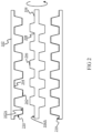
- Figure 2 illustrates a cross-section of a portion of the tube 102 with the cathode 104 rotating inside the tube 102, such that an outer surface 104A of the cathode 104 is facing the inner surface 102A of the tube 102.
- the tube 102 may have a first surface profile formed on the inner surface 102A of the tube 102 and the cathode 104 may include a second surface profile formed on an outer surface 104A of the cathode 104.
- the first surface profile and the second surface profile can be rifles on their respective surfaces.
- the first surface profile may include a set of peaks 202 and valleys 204 formed between adjacent peaks 202.
- the second surface profile may include peaks 206 and valleys 206.
- An aggregation of surface areas of the peaks 202 and valleys 206 may define a surface area of the first surface profile and the aggregation of surface areas of the peaks 206 and valleys 208 may define a surface area of the second surface profile.
- the surface area ratio of the first surface profile and the second surface profile is maintained within a predetermined range. In this range, transfer of ions via the electrolyte is maintained at preset rate which enables the process of anodization on the inner surface 102A to occur at a homogenous rate on the inner surface 102A. Therefore, an anodized coat 210 so formed may have same thickness at the peak 202 and at the valley 206.
- the cathode 104 is rotated inside the tube 102 at a predetermined rotational speed.
- the predetermined rotational speed is in a range of 1 to 50 Rotations Per Minute (RPM). Further, the predetermined rotational speed may depend on various factors. For instance, the predetermined rotational speed on the surface area ratio, the length up to which the second surface profile is extending. Rotating the cathode 104 at the predetermined rotational speed ensures that a predetermined distance is maintained between the outer surface 104A and the inner surface 102A so that a stable transfer of ions via the electrolyte is maintained to form the anodized coat.
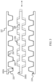
- Figure 2 illustrates a cross-section of a portion of the tube 102 with the cathode 104 oscillating inside the tube 102.
- the cathode holder 110 (shown in Figure 1 ) oscillates the cathode 104 at a predetermined rate to change its position along a length of the tube 102 as shown by the dotted lines. Further, the cathode 104 is oscillated so that the distance between the peaks 206 on the cathode 104 and valleys 204 in the inner surface 102A can be reduced to maintain the preset rate of transfer of ions via the electrolyte.
- the predetermined rate of oscillation may depend on various factors, like the size of peaks 202 and valleys 204, surface area ratio, and area up to which the first surface profile and the second surface profiles extend on the tube 102 and the cathode 104 respectively, among other examples.
- the cathode holder 110 may impart both oscillatory and rotational motion. In such a scenario, the motions depicted in Figures 2 and 3 will be executed simultaneously.
- FIG. 4 illustrates a method for anodizing the tube.
- the order in which the method steps are described below is not intended to be construed as a limitation, and any number of the described method steps may be combined in any appropriate order to execute the method or an alternative method. Additionally, individual steps may be deleted from the method without departing from the spirit and scope of the subject matter described herein.
- the method 400 may be performed partially or completely by the anodization apparatus 100 shown in Figure 1 .
- the method begins at step 402 at which the tube 102 having a first surface profile on its inner surface 102A is mounted on the anode holder 108. Thereafter, at step 404, the cathode having a second surface profile on the outer surface 104A thereof is mounted on the cathode holder 110, such that the outer surface 104A faces the inner surface 102A of the tube 102.
- the pumping unit 112 pumps an electrolyte through an annulus between the outer surface 104A and the inner surface 102A.
- an electric potential is applied by the power unit 106 across the tube 102 and the cathode 104 via the anode holder 108 and the cathode holder 110, respectively.
- Application of the electric potential and the maintenance of the surface area ratio between the first surface profile and the second surface profile facilitates the formation of a homogenized anodized coat on the first surface profile.
- the method 400 may also include a step 408 of rotating the cathode 104 and, at step 410 oscillating the cathode 104 in a manner explained above with respect to Figures 2 and 3 , respectively.
- maintaining the surface area ratio between the first surface profile and the second surface profile facilitates the formation of a homogenized anodized coat on the first surface profile.
- the oscillatory and rotating motion ensures a stable transfer of ions to ensure that the anodized coat of homogenous thickness across the complete surface of the inner surface 102A of the tube 102.
Landscapes
- Chemical & Material Sciences (AREA)
- Engineering & Computer Science (AREA)
- Chemical Kinetics & Catalysis (AREA)
- Electrochemistry (AREA)
- Materials Engineering (AREA)
- Metallurgy (AREA)
- Organic Chemistry (AREA)
- Automation & Control Theory (AREA)
- Physics & Mathematics (AREA)
- Thermal Sciences (AREA)
- Mechanical Engineering (AREA)
- General Engineering & Computer Science (AREA)
- Electrolytic Production Of Non-Metals, Compounds, Apparatuses Therefor (AREA)
- Physical Vapour Deposition (AREA)
- Electroplating Methods And Accessories (AREA)
Abstract
An anodization apparatus is disclosed that includes an anode holder adapted to hold a tube, such that the tube is adapted to receive electrolyte and the tube has a first surface profile formed on an inner surface of the tube. The anodization apparatus also includes a cathode holder adapted to hold a cathode concentrically in the tube, such that the cathode has a second surface profile formed an outer surface of the cathode and the outer surface faces the inner surface of the tube. The cathode holder and the anode holder are adapted to supply electric potential of a predetermined current density to the cathode and the tube, respectively, and a surface area ratio between the first surface profile and the second surface profile is maintained within a predetermined range to facilitate formation of a homogenized anodized coat on the first surface profile.
Description
- The disclosure relates to aspects of forming an anodized coat on an inner surface of a tube.
- Metallic tubes, such as Aluminum tubes are used for transferring heat from a fluid flowing therein to an outer surface of the tube. One of the areas of application of such tubes is in air conditioning units as chiller tubes to discharge heat from a refrigerant flowing therethrough. The tubes may have enhancement formed on an inner surface of the tube to increase the surface area which increases the heat transmission capacity of the tube. The enhancement, in one example, can be rifles or any other structure formed on the inner surface to increase a surface area that comes in contact with the fluid flowing through the tube thereby increasing the heat transfer. Generally, the tubes are anodized to form a corrosion-resistant coating to prevent galvanic corrosion caused by the fluid flowing through the tube.
- The coating is currently formed by an anodization process. However, the coating may not have a uniform thickness across the inner surface of the tube due to enhancement on the inner surface. In one example, enhancements on the inner surface, such as valleys may have a layer of the coating of lesser thickness than a layer of the coating at other regions in the enhancement. As a result, the coating in the valley is more susceptible to erosion and accordingly, can be a starting point of corrosion.
- This summary is provided to introduce a selection of concepts, in a simplified format, that is further described in the detailed description of the invention. This summary is neither intended to identify key or essential inventive concepts of the invention nor is it intended for determining the scope of the invention.
- According to a first aspect of the invention, a method of anodizing an inner surface of a tube is disclosed. The method includes mounting the tube on an anode holder, wherein the tube has a first surface profile formed on an inner surface of the tube. In addition, the method includes mounting a cathode on a cathode holder to place the cathode concentrically inside the tube, wherein the cathode has a second surface profile formed an outer surface of the cathode and the outer surface faces the inner surface of the tube. The method also includes pumping an electrolyte through an annulus between the outer surface and the inner surface. Further, the method includes applying an electric potential across the tube and the cathode via the anode holder and the cathode holder, respectively. Furthermore, a surface area ratio between the first surface profile and the second surface profile is maintained within a predetermined range to facilitate the formation of a homogenized anodized coat on the first surface profile.
- Optionally, the method includes oscillating, by a linear drive unit of the cathode holder, the cathode linearly at a predetermined rate along a length of the tube.
- Optionally, the method includes rotating, by a rotational drive unit of the cathode holder, the cathode at a predetermined rotational speed inside the tube.
- Optionally, moving the cathode comprises maintaining a predetermined distance between the surface profiles of the cathode and the tube.
- Optionally, the predetermined range of surface area ratio is 9:1 to 1.5:1.
- Optionally, a tube is disclosed as having a first surface profile formed on the inner surface and an anodized coat formed on the first surface profile, by the method in one or more embodiments.
- According to a second aspect of the invention, an anodization apparatus is disclosed that includes an anode holder adapted to hold a tube, such that the tube is adapted to receive electrolyte and the tube has a first surface profile formed on an inner surface of the tube. The anodization apparatus also includes a cathode holder adapted to hold a cathode concentrically in the tube, such that the cathode has a second surface profile formed an outer surface of the cathode and the outer surface faces the inner surface of the tube. The cathode holder and the anode holder are adapted to supply electric potential of a predetermined current density to the cathode and the tube, respectively, and a surface area ratio between the first surface profile and the second surface profile is maintained within a predetermined range to facilitate the formation of a homogenized anodized coat on the first surface profile.
- Optionally, a power source is adapted to apply the electric potential of the predetermined current density across the cathode holder and the anode holder.
- Optionally, a pumping unit is adapted to pump the electrolyte through the tube.
- Optionally, the cathode holder includes a pair of clamp contacts configured to supply the electric potential to the cathode, a linear drive unit configured to oscillate the cathode linearly at a predetermined rate along a length of the tube; and a rotational drive unit configured to rotate the cathode at a predetermined rotational speed inside the tube.
- Optionally, the anode holder includes a pair of clamp contacts configured to supply the electric potential to the cathode.
- Optionally, the magnitude of the predetermined current density is in a range of 4 to 20 amps/square foot.
- Optionally, the first surface profile and the second surface are rifles.
- Optionally, the predetermined rate is in a range of 0.5 to 1000 rotations per minute (RPM), and the predetermined rotational speed is in a range of 1 to 50 Rotations Per Minute (RPM).
- Optionally, the cathode is made of Aluminum alloy.
- Optionally, the predetermined range of the surface area ratio is 9:1 to 1.5:1.
- To further clarify the advantages and features of the disclosure, a more particular description of the invention will be rendered by reference to specific embodiments thereof, which are illustrated in the appended drawings. It is appreciated that these drawings depict only typical embodiments of the invention and are therefore not to be considered limiting of its scope. The invention will be described and explained with additional specificity and detail in the accompanying drawings.
- These and other features, aspects, and advantages of the disclosure will become better understood when the following detailed description is read with reference to the accompanying drawings in which like characters represent like parts throughout the drawings, wherein:
-
Figure 1 illustrates a schematic of an anodization apparatus; -
Figure 2 illustrates a cross-section of a tube with a cathode of the anodization apparatus rotating inside the tube; -
Figure 3 illustrates a cross-section of the tube with the cathode of the anodization apparatus oscillating inside the tube; and -
Figure 4 illustrates a flowchart depicting a method for anodizing the tube; - Further, skilled artisans will appreciate that elements in the drawings are illustrated for simplicity and may not have necessarily been drawn to scale. Furthermore, in terms of the construction of the device, one or more components of the device may have been represented in the drawings by conventional symbols, and the drawings may show only those specific details that are pertinent to understanding the embodiments of the disclosure so as not to obscure the drawings with details that will be readily apparent to those of ordinary skill in the art having the benefit of the description herein.
- For the purpose of promoting an understanding of the principles of the disclosure, reference will now be made to the various embodiments and specific language will be used to describe the same. It will nevertheless be understood that no limitation of the scope of the invention is thereby intended, such alterations and further modifications in the illustrated system, and such further applications of the principles of the invention as illustrated therein being contemplated as would normally occur to one skilled in the art to which the invention relates. The scope of the invention is set out in the appended claims.
- It will be understood by those skilled in the art that the foregoing general description and the following detailed description are explanatory of the disclosure and are not intended to be restrictive thereof.
- Reference throughout this specification to "an aspect", "another aspect" or similar language means that a particular feature, structure, or characteristic described in connection with the embodiment is included in at least one embodiment of the disclosure. Thus, appearances of the phrase "in an embodiment", "in another embodiment", "some embodiments", "one or more embodiments" and similar language throughout this specification may, but do not necessarily, all refer to the same embodiment.
- The terms "comprises", "comprising", or any other variations thereof, are intended to cover a non-exclusive inclusion, such that a process or method that comprises a list of steps does not include only those steps but may include other steps not expressly listed or inherent to such process or method. Similarly, one or more devices or sub-systems or elements or structures or components proceeded by "comprises... a" does not, without more constraints, preclude the existence of other devices or other sub-systems or other elements or other structures or other components or additional devices or additional sub-systems or additional elements or additional structures or additional components.
- Embodiments of the disclosure will be described below in detail with reference to the accompanying drawings.
-
Figure 1 illustrates ananodization apparatus 100 which may be used for forming a homogenous coating on atube 102. Theanodization apparatus 100 is adapted to perform an electrochemical process referred to as the anodization process to create a non-reactive anodized coat, on an inner surface of thetube 102. During the anodization process, aninner surface 102A of thetube 102 undergoes a controlled corrosion. The non-reactive anodized coat can be a metal oxide layer that may protect theinner surface 102A of thetube 102 from a fluid flowing through thetube 102. Thetube 102 may have enhancements on theinner surface 102A based on an area of application of thetube 102. For example, thetube 102 may have enhancements to increase the area of theinner surface 102A of thetube 102. The enhancements, in one example, can be rifles. - In one example, the
anodization apparatus 100 may employ an electrolyte and acathode 104 to form the metal oxide. In one example, theanodization apparatus 100 may be used to coat thetube 102 made of an Aluminum alloy, such as 6061, or 6063 alloy. Further, theanodization apparatus 100 may be used to create a coating on any type of Aluminum alloy by changing parameters of theanodization apparatus 100, such as an applied voltage, a current, and a type of electrolyte. Theanodization apparatus 100 is designed in such a way that the inner surface is completely covered by the oxide layer irrespective of the surface profile of theinner surface 102A. - The
anodization apparatus 100 may employ various implements that enable theanodization apparatus 100 to form an anodized coat of homogenous thickness. For instance, theanodization apparatus 100 uses thecathode 104 that may have a surface profile, unlike the currently used cathode that has a smooth surface. Further, a ratio of the surface area between thecathode 104 and thetube 102 is maintained within a predetermined range to form the anodized coat of homogenous thickness. Moreover, theanodization apparatus 100 may actuate thecathode 104 relative to thetube 102 to further augment the formation of anodized coat. Details of each of the aforementioned implements will be discussed later. - The
anodization apparatus 100 may include, but is not limited to, apower unit 106, ananode holder 108, acathode holder 110, and apumping unit 112, details of which will be provided later. Thepower unit 106 is adapted to provide electric potential across theanode holder 108 and thecathode holder 110. Thepower unit 106 may be configured to provide direct current (DC). Further, thepower unit 106 may receive power from an alternating current (AC) source, such as a mains supply. Thepower unit 106, in order to convert the AC supply to a DC supply, may employ arectifier 114. Therectifier 114 may either be a half-bridge rectifier or a full-bridge rectifier. Although not shown, thepower unit 106 may include additional electrical components, such as a voltage booster and DC-DC converter to provide the electric potential of a predetermined current density to thecathode 104 and thetube 102 via thecathode holder 110 and theanode holder 108 respectively. In one example, thepower unit 106 may provide an electrical potential with a predetermined current density. Further, a magnitude of the predetermined current density may be in a range of 4 to 20 amps/square foot. - The
anode holder 108, in one example, may be configured to hold thetube 102 in a predefined configuration and may act as a positive terminal of thepower unit 106. Theanode holder 108 may also include a pair of clamp contacts that performs two tasks. First, the clamp contacts hold thetube 102 at a preset configuration and second, the clamp contacts may secure contact so that electric potential is applied to thetube 102. Theanode holder 108 may be made of graphite or any other material suitable for holding thetube 102. Although not shown, theanodization apparatus 100 may includemultiple anode holders 108 that may be used to supply the electric potential ofmultiple tubes 102 in parallel. - In this example, the
anode holder 108 is shown to make contact with anouter surface 102B at an end of thetube 102. In another example, theanode holder 108 may be connected to a central region of thetube 102. In yet another example, theanode holder 108 may have a greater width to connect with a greater area of theouter surface 102B. An increased contact point or contact area and distribution of the current over a greater area of theouter surface 102B of thetube 102 allows for even distribution of the current. - For example, the
cathode holder 110 may be configured to receive thecathode 104. Thecathode holder 110 may be adapted to perform two tasks. First, thecathode holder 110 may provide negative electric potential to thecathode 104 and the second, thecathode holder 110 may move thecathode 104 relative to thetube 102 to achieve the anodized coat of homogenous thickness. For instance, thecathode holder 110 may include a pair of clamp contacts configured to supply the negative electric potential. In addition, thecathode holder 110 may include alinear drive unit 118 that may be coupled to an end of thecathode 104. Thelinear drive unit 118 may be configured to oscillate thecathode 104 inside thetube 102 along a length of thetube 102. Such an oscillation may change an effective gap between thecathode 104 and thetube 102. The effective distance may be defined as a shortest distance between two closest points on theouter surface 104A and theinner surface 102A respectively. Thelinear drive unit 118, in one example, maybe a reciprocating type machine and may oscillate thecathode 104 at a predetermined rate. The predetermined rate can be 0.5 to 1000 Rotations Per Minute. - In addition, the
cathode holder 110 may include arotary drive unit 120 coupled to the end of thecathode 104. Therotary drive unit 120 is configured to rotate thecathode 104 inside thetube 102. Therotary drive unit 120 may be designed to rotate thecathode 104 at a predetermined rotational speed. In one example, the predetermined rotational speed is in a range of 1 to 50 Rotations Per Minute (RPM). Further, in order to support the rotation of thecathode 104, thecathode holder 110 may include a pair ofbearings 122 attached to either end of thecathode 104 to support the rotation thereof. Thecathode holder 110 is configured in such a way that thecathode 104 may be rotated and the translated back and forth at the same time. - The
pumping unit 112, in one example, may be configured to pump electrolytes through thetube 102. Thepumping unit 112 may be a part of a fluid circuit that supplies electrolytes to thetube 102. Although not shown, thepumping unit 112 may be connected to a first end of thetube 102 via a hose, such that the electrolyte flows into thetube 102 denoted by aninlet path 124. Further, a second end of thetube 102 is denoted by theoutlet path 126. In one example, the fluid circuit may be a closed loop circuit, such that the fluid return to thepumping unit 112 after exiting thetube 102. In another example, the fluid circuit is an open loop circuit, such that thepumping unit 112 pumps fresh electrolytes to thetube 102. The pumping of the electrolyte by thepumping unit 112 not only ensures the presence of electrolyte in thetube 102 to ensure a constant anodization process but also removes hydrogen gas generated at an outer surface of thecathode 104 during the anodization process. Removal of gas ensures that thecathode 104 surfaces are exposed for the anodization process. - The
anodization apparatus 100 may also include additional implements that may assist the movement of thecathode 104. For instance, theanodization apparatus 100 may include one ormore spacers 128 that support thecathode 104 inside thetube 102. Thespacer 128 is non-conductive in nature and may be configured to keep thecathode 104 at the centre of thetube 102 so that thecathode 104 does not contact thetube 102 to prevent shorting and/or arching in theanodization apparatus 100. In one example, the number ofspacers 128 may depend on the length, and thickness of thecathode 104. Eachspacer 128 may include a hole at its centre to receive thecathode 104. In addition, thespacer 128 may include a plurality of cut-out portions that allows the electrolyte to pass through. Thespacer 128 may have a diameter slightly less than the bore of thetube 102, such that thespacer 128 can be easily inserted and removed while at the same time installed orthogonal to a length of thetube 102. - According to this disclosure, the
cathode 104 used in theanodization apparatus 100 may have a surface profile in such a way that the ratio of the area of the surface profile of theinner surface 102A oftube 102 is within a predetermined range so that homogenised anodized coat is formed. Details of the surface profiles of both thecathode 104 and thetube 102 and the motion imparted by thecathode holder 110 will be discussed with respect toFigures 2 and3 . -
Figure 2 illustrates a cross-section of a portion of thetube 102 with thecathode 104 rotating inside thetube 102, such that anouter surface 104A of thecathode 104 is facing theinner surface 102A of thetube 102. Further, thetube 102 may have a first surface profile formed on theinner surface 102A of thetube 102 and thecathode 104 may include a second surface profile formed on anouter surface 104A of thecathode 104. In one example, the first surface profile and the second surface profile can be rifles on their respective surfaces. In one example, the first surface profile may include a set ofpeaks 202 andvalleys 204 formed betweenadjacent peaks 202. Similarly, the second surface profile may includepeaks 206 andvalleys 206. An aggregation of surface areas of thepeaks 202 andvalleys 206 may define a surface area of the first surface profile and the aggregation of surface areas of thepeaks 206 andvalleys 208 may define a surface area of the second surface profile. Further, the surface area ratio of the first surface profile and the second surface profile is maintained within a predetermined range. In this range, transfer of ions via the electrolyte is maintained at preset rate which enables the process of anodization on theinner surface 102A to occur at a homogenous rate on theinner surface 102A. Therefore, ananodized coat 210 so formed may have same thickness at thepeak 202 and at thevalley 206. - To further augment the formation of a homogenized coating, the
cathode 104 is rotated inside thetube 102 at a predetermined rotational speed. The predetermined rotational speed is in a range of 1 to 50 Rotations Per Minute (RPM). Further, the predetermined rotational speed may depend on various factors. For instance, the predetermined rotational speed on the surface area ratio, the length up to which the second surface profile is extending. Rotating thecathode 104 at the predetermined rotational speed ensures that a predetermined distance is maintained between theouter surface 104A and theinner surface 102A so that a stable transfer of ions via the electrolyte is maintained to form the anodized coat. -
Figure 2 illustrates a cross-section of a portion of thetube 102 with thecathode 104 oscillating inside thetube 102. The cathode holder 110 (shown inFigure 1 ) oscillates thecathode 104 at a predetermined rate to change its position along a length of thetube 102 as shown by the dotted lines. Further, thecathode 104 is oscillated so that the distance between thepeaks 206 on thecathode 104 andvalleys 204 in theinner surface 102A can be reduced to maintain the preset rate of transfer of ions via the electrolyte. The predetermined rate of oscillation may depend on various factors, like the size ofpeaks 202 andvalleys 204, surface area ratio, and area up to which the first surface profile and the second surface profiles extend on thetube 102 and thecathode 104 respectively, among other examples. - In one example, the
cathode holder 110 may impart both oscillatory and rotational motion. In such a scenario, the motions depicted inFigures 2 and3 will be executed simultaneously. - A method for forming an anodized coat on the
inner surface 102A of thetube 102 will now be described with respect toFigure 4 which illustrates a method for anodizing the tube. The order in which the method steps are described below is not intended to be construed as a limitation, and any number of the described method steps may be combined in any appropriate order to execute the method or an alternative method. Additionally, individual steps may be deleted from the method without departing from the spirit and scope of the subject matter described herein. - In one example, the
method 400 may be performed partially or completely by theanodization apparatus 100 shown inFigure 1 . The method begins atstep 402 at which thetube 102 having a first surface profile on itsinner surface 102A is mounted on theanode holder 108. Thereafter, atstep 404, the cathode having a second surface profile on theouter surface 104A thereof is mounted on thecathode holder 110, such that theouter surface 104A faces theinner surface 102A of thetube 102. - Further, at
step 406, thepumping unit 112 pumps an electrolyte through an annulus between theouter surface 104A and theinner surface 102A. Finally, atstep 408, an electric potential is applied by thepower unit 106 across thetube 102 and thecathode 104 via theanode holder 108 and thecathode holder 110, respectively. Application of the electric potential and the maintenance of the surface area ratio between the first surface profile and the second surface profile facilitates the formation of a homogenized anodized coat on the first surface profile. Themethod 400 may also include astep 408 of rotating thecathode 104 and, at step 410 oscillating thecathode 104 in a manner explained above with respect toFigures 2 and3 , respectively. - According to this disclosure, maintaining the surface area ratio between the first surface profile and the second surface profile facilitates the formation of a homogenized anodized coat on the first surface profile. Moreover, the oscillatory and rotating motion ensures a stable transfer of ions to ensure that the anodized coat of homogenous thickness across the complete surface of the
inner surface 102A of thetube 102. - While specific language has been used to describe the disclosure, any limitations arising on account thereto, are not intended. As would be apparent to a person in the art, various working modifications may be made to the method in order to implement the inventive concept as taught herein. The drawings and the foregoing description give examples of embodiments. Those skilled in the art will appreciate that one or more of the described elements may well be combined into a single functional element. Alternatively, certain elements may be split into multiple functional elements. Elements from one embodiment may be added to another embodiment.
Claims (15)
- A method (400) of anodising an inner surface of a tube, comprising:mounting (402) the tube on an anode holder, wherein the tube has a first surface profile formed on an inner surface of the tube;mounting (404) a cathode on a cathode holder to place the cathode concentrically inside the tube, wherein the cathode has a second surface profile formed an outer surface of the cathode and the outer surface faces the inner surface of the tube;pumping (406) an electrolyte through an annulus between the outer surface and the inner surface; andapplying (408) an electric potential across the tube and the cathode via the anode holder and the cathode holder, respectively,wherein a surface area ratio between the first surface profile and the second surface profile is maintained within a predetermined range to facilitate formation of a homogenised anodized coat on the first surface profile.
- The method of claim 1, comprising:
oscillating, by a linear drive unit of the cathode holder, the cathode linearly at a predetermined rate along a length of the tube. - The method of any one of the preceding claims, comprising:
rotating, by a rotational drive unit of the cathode holder, the cathode at a predetermined rotational speed inside the tube. - The method of any one of the preceding claims, wherein moving the cathode comprises maintaining a predetermined distance between surface profiles of the cathode and the tube.
- The method of any one of the preceding claims, wherein the predetermined range of surface area ratio is 9:1 to 1.5:1.
- A tube having a first surface profile formed on inner surface and an anodized coat formed on the first surface profile, by the method as claimed in claims 1 to 5.
- An anodization apparatus (100) comprising:an anode holder (108) adapted to hold a tube (102), wherein the tube is adapted to receive electrolyte and the tube has a first surface profile formed on an inner surface (102A) of the tube; anda cathode holder (110) adapted to hold a cathode (104) concentrically in the tube, wherein the cathode has a second surface profile (104A) formed an outer surface of the cathode and the outer surface faces the inner surface of the tube,wherein the cathode holder and the anode holder are adapted to supply electric potential of a predetermined current density to the cathode and the tube, respectively, andwherein a surface area ratio between the first surface profile and the second surface profile is maintained within a predetermined range to facilitate formation of a homogenised anodized coat on the first surface profile.
- The anodization apparatus of claim 7, comprising a power source (106) adapted to apply the electric potential of the predetermined current density across the cathode holder and the anode holder.
- The anodization apparatus of claim 7, comprising a pumping unit (112) adapted to pump the electrolyte through the tube.
- The anodization apparatus of any one of the preceding claims, wherein the cathode holder comprising:a pair of clamp contacts configured to supply the electric potential to the cathode;a linear drive unit (118) configured to oscillate the cathode linearly at a predetermined rate along a length of the tube; anda rotational drive unit (120) configured to rotate the cathode at a predetermined rotational speed inside the tube.
- The anodization apparatus of any one of the preceding claims, wherein the anode holder comprising a pair of clamp contacts configured to supply the electric potential to the cathode.
- The anodization apparatus of any one of the preceding claims, wherein a magnitude of the predetermined current density is in a range of 4 to 20 amps/square foot.
- The anodization apparatus of any one of the preceding claims, wherein the first surface profile and the second surface are rifles.
- The anodization apparatus of any one of the preceding claims, whereinthe predetermined rate is in a range of 0.5 to 1000 rotations per minute,the predetermined rotational speed is in a range of 1 to 50 rotations per minute.
- The anodization apparatus of any one of the preceding claims, wherein
the cathode is made of Aluminium alloy; and/or wherein the predetermined range of the surface area ratio is 9:1 to 1.5:1.
Applications Claiming Priority (1)
| Application Number | Priority Date | Filing Date | Title |
|---|---|---|---|
| US202363511222P | 2023-06-30 | 2023-06-30 |
Publications (1)
| Publication Number | Publication Date |
|---|---|
| EP4509642A1 true EP4509642A1 (en) | 2025-02-19 |
Family
ID=91759603
Family Applications (1)
| Application Number | Title | Priority Date | Filing Date |
|---|---|---|---|
| EP24185816.6A Pending EP4509642A1 (en) | 2023-06-30 | 2024-07-01 | Apparatus and method for anodising an inner surface of a tube |
Country Status (3)
| Country | Link |
|---|---|
| US (1) | US20250003107A1 (en) |
| EP (1) | EP4509642A1 (en) |
| CN (1) | CN119221063A (en) |
Citations (4)
| Publication number | Priority date | Publication date | Assignee | Title |
|---|---|---|---|---|
| JP2000205782A (en) * | 1999-01-11 | 2000-07-28 | Hitachi Cable Ltd | Aluminum tube with inner groove and method of manufacturing the same |
| JP2005171288A (en) * | 2003-12-09 | 2005-06-30 | Ebara Corp | Plating device and plating method |
| JP2006233273A (en) * | 2005-02-24 | 2006-09-07 | Mitsubishi Heavy Ind Ltd | Anodization treatment for inner wall of piping, and configuration of cathode member |
| US20150275388A1 (en) * | 2014-03-27 | 2015-10-01 | Aisin Keikinzoku Co., Ltd. | Electrolytic apparatus and surface treatment method using the same |
-
2024
- 2024-06-11 US US18/739,797 patent/US20250003107A1/en active Pending
- 2024-06-28 CN CN202410854984.3A patent/CN119221063A/en active Pending
- 2024-07-01 EP EP24185816.6A patent/EP4509642A1/en active Pending
Patent Citations (4)
| Publication number | Priority date | Publication date | Assignee | Title |
|---|---|---|---|---|
| JP2000205782A (en) * | 1999-01-11 | 2000-07-28 | Hitachi Cable Ltd | Aluminum tube with inner groove and method of manufacturing the same |
| JP2005171288A (en) * | 2003-12-09 | 2005-06-30 | Ebara Corp | Plating device and plating method |
| JP2006233273A (en) * | 2005-02-24 | 2006-09-07 | Mitsubishi Heavy Ind Ltd | Anodization treatment for inner wall of piping, and configuration of cathode member |
| US20150275388A1 (en) * | 2014-03-27 | 2015-10-01 | Aisin Keikinzoku Co., Ltd. | Electrolytic apparatus and surface treatment method using the same |
Also Published As
| Publication number | Publication date |
|---|---|
| US20250003107A1 (en) | 2025-01-02 |
| CN119221063A (en) | 2024-12-31 |
Similar Documents
| Publication | Publication Date | Title |
|---|---|---|
| EP1041178B1 (en) | Anodizing method and apparatus for performing the same | |
| JP2014179193A (en) | Aluminum base material for tab lead and tab lead | |
| CN107513746A (en) | Light alloy radiator surface anticorrosion heat conduction composite coating, preparation method thereof and light alloy radiator | |
| CN102268708B (en) | Microarc oxidation processing method and device | |
| JP2018090897A (en) | Anodic oxide film and method for producing the same | |
| US20250003107A1 (en) | Apparatus and method for anodising an inner surface of a tube | |
| JP2009114524A (en) | Method for anodizing aluminum pipe for base of photoconductor drum, and base of photoconductor drum | |
| US9863056B2 (en) | Device for electrochemical treatment, locally in particular, of a conductor substrate | |
| JP3705457B2 (en) | Method for anodizing aluminum material | |
| JP2024546962A (en) | Inner surface electrochemically treated electrodes | |
| JP4038041B2 (en) | Electrolytic treatment equipment | |
| CN110026628B (en) | Electrochemical machining device based on magneto-deformable electrode and electrochemical machining method thereof | |
| JP5907049B2 (en) | Surface treatment apparatus and treatment method thereof | |
| CN114990687B (en) | Electrochemical polishing device, application method thereof and workpiece inserted into pump through guide pipe | |
| JP3729013B2 (en) | Manufacturing method of electrode foil for aluminum electrolytic capacitor | |
| JP7689632B2 (en) | Electrolysis device, electrolysis system, and electrolysis method in which energy is supplied by AC induction | |
| Ayyappan et al. | Experimental Study on Material Removal Rate and Over-Cut in Electrochemical Machining of Monel 400 Alloys with Coated Tools | |
| JPS6235030Y2 (en) | ||
| JPH07285027A (en) | Electropolishing method | |
| CN118932452A (en) | A non-immersion micro-arc oxidation process and device | |
| JP3202447B2 (en) | Method for forming anodized film on aluminum alloy parts | |
| JP2825975B2 (en) | Electrical connector for electrolytic polymerization | |
| JP2003311545A (en) | Electrochemical machining method and device used for the same | |
| RU2827632C1 (en) | Method of anodizing hollow part from aluminum alloy | |
| JP7506747B2 (en) | Thermal Conductive Materials |
Legal Events
| Date | Code | Title | Description |
|---|---|---|---|
| PUAI | Public reference made under article 153(3) epc to a published international application that has entered the european phase |
Free format text: ORIGINAL CODE: 0009012 |
|
| STAA | Information on the status of an ep patent application or granted ep patent |
Free format text: STATUS: THE APPLICATION HAS BEEN PUBLISHED |
|
| AK | Designated contracting states |
Kind code of ref document: A1 Designated state(s): AL AT BE BG CH CY CZ DE DK EE ES FI FR GB GR HR HU IE IS IT LI LT LU LV MC ME MK MT NL NO PL PT RO RS SE SI SK SM TR |
|
| STAA | Information on the status of an ep patent application or granted ep patent |
Free format text: STATUS: REQUEST FOR EXAMINATION WAS MADE |
|
| 17P | Request for examination filed |
Effective date: 20250819 |