EP4509458A2 - Direction-of-travel-based inhibition of speed control based on truck-to-truck proximity detection - Google Patents
Direction-of-travel-based inhibition of speed control based on truck-to-truck proximity detection Download PDFInfo
- Publication number
- EP4509458A2 EP4509458A2 EP24212769.4A EP24212769A EP4509458A2 EP 4509458 A2 EP4509458 A2 EP 4509458A2 EP 24212769 A EP24212769 A EP 24212769A EP 4509458 A2 EP4509458 A2 EP 4509458A2
- Authority
- EP
- European Patent Office
- Prior art keywords
- vehicle
- travel
- proximity
- truck
- slow
- Prior art date
- Legal status (The legal status is an assumption and is not a legal conclusion. Google has not performed a legal analysis and makes no representation as to the accuracy of the status listed.)
- Granted
Links
Images



Classifications
-
- B—PERFORMING OPERATIONS; TRANSPORTING
- B60—VEHICLES IN GENERAL
- B60W—CONJOINT CONTROL OF VEHICLE SUB-UNITS OF DIFFERENT TYPE OR DIFFERENT FUNCTION; CONTROL SYSTEMS SPECIALLY ADAPTED FOR HYBRID VEHICLES; ROAD VEHICLE DRIVE CONTROL SYSTEMS FOR PURPOSES NOT RELATED TO THE CONTROL OF A PARTICULAR SUB-UNIT
- B60W30/00—Purposes of road vehicle drive control systems not related to the control of a particular sub-unit, e.g. of systems using conjoint control of vehicle sub-units
- B60W30/14—Adaptive cruise control
- B60W30/143—Speed control
- B60W30/146—Speed limiting
-
- B—PERFORMING OPERATIONS; TRANSPORTING
- B66—HOISTING; LIFTING; HAULING
- B66F—HOISTING, LIFTING, HAULING OR PUSHING, NOT OTHERWISE PROVIDED FOR, e.g. DEVICES WHICH APPLY A LIFTING OR PUSHING FORCE DIRECTLY TO THE SURFACE OF A LOAD
- B66F9/00—Devices for lifting or lowering bulky or heavy goods for loading or unloading purposes
- B66F9/06—Devices for lifting or lowering bulky or heavy goods for loading or unloading purposes movable, with their loads, on wheels or the like, e.g. fork-lift trucks
-
- B—PERFORMING OPERATIONS; TRANSPORTING
- B60—VEHICLES IN GENERAL
- B60W—CONJOINT CONTROL OF VEHICLE SUB-UNITS OF DIFFERENT TYPE OR DIFFERENT FUNCTION; CONTROL SYSTEMS SPECIALLY ADAPTED FOR HYBRID VEHICLES; ROAD VEHICLE DRIVE CONTROL SYSTEMS FOR PURPOSES NOT RELATED TO THE CONTROL OF A PARTICULAR SUB-UNIT
- B60W30/00—Purposes of road vehicle drive control systems not related to the control of a particular sub-unit, e.g. of systems using conjoint control of vehicle sub-units
- B60W30/08—Active safety systems predicting or avoiding probable or impending collision or attempting to minimise its consequences
- B60W30/09—Taking automatic action to avoid collision, e.g. braking and steering
-
- B—PERFORMING OPERATIONS; TRANSPORTING
- B60—VEHICLES IN GENERAL
- B60W—CONJOINT CONTROL OF VEHICLE SUB-UNITS OF DIFFERENT TYPE OR DIFFERENT FUNCTION; CONTROL SYSTEMS SPECIALLY ADAPTED FOR HYBRID VEHICLES; ROAD VEHICLE DRIVE CONTROL SYSTEMS FOR PURPOSES NOT RELATED TO THE CONTROL OF A PARTICULAR SUB-UNIT
- B60W30/00—Purposes of road vehicle drive control systems not related to the control of a particular sub-unit, e.g. of systems using conjoint control of vehicle sub-units
- B60W30/08—Active safety systems predicting or avoiding probable or impending collision or attempting to minimise its consequences
- B60W30/095—Predicting travel path or likelihood of collision
- B60W30/0953—Predicting travel path or likelihood of collision the prediction being responsive to vehicle dynamic parameters
-
- B—PERFORMING OPERATIONS; TRANSPORTING
- B60—VEHICLES IN GENERAL
- B60W—CONJOINT CONTROL OF VEHICLE SUB-UNITS OF DIFFERENT TYPE OR DIFFERENT FUNCTION; CONTROL SYSTEMS SPECIALLY ADAPTED FOR HYBRID VEHICLES; ROAD VEHICLE DRIVE CONTROL SYSTEMS FOR PURPOSES NOT RELATED TO THE CONTROL OF A PARTICULAR SUB-UNIT
- B60W50/00—Details of control systems for road vehicle drive control not related to the control of a particular sub-unit, e.g. process diagnostic or vehicle driver interfaces
- B60W50/0098—Details of control systems ensuring comfort, safety or stability not otherwise provided for
-
- B—PERFORMING OPERATIONS; TRANSPORTING
- B65—CONVEYING; PACKING; STORING; HANDLING THIN OR FILAMENTARY MATERIAL
- B65G—TRANSPORT OR STORAGE DEVICES, e.g. CONVEYORS FOR LOADING OR TIPPING, SHOP CONVEYOR SYSTEMS OR PNEUMATIC TUBE CONVEYORS
- B65G1/00—Storing articles, individually or in orderly arrangement, in warehouses or magazines
- B65G1/02—Storage devices
- B65G1/04—Storage devices mechanical
- B65G1/137—Storage devices mechanical with arrangements or automatic control means for selecting which articles are to be removed
- B65G1/1373—Storage devices mechanical with arrangements or automatic control means for selecting which articles are to be removed for fulfilling orders in warehouses
- B65G1/1375—Storage devices mechanical with arrangements or automatic control means for selecting which articles are to be removed for fulfilling orders in warehouses the orders being assembled on a commissioning stacker-crane or truck
-
- B—PERFORMING OPERATIONS; TRANSPORTING
- B66—HOISTING; LIFTING; HAULING
- B66F—HOISTING, LIFTING, HAULING OR PUSHING, NOT OTHERWISE PROVIDED FOR, e.g. DEVICES WHICH APPLY A LIFTING OR PUSHING FORCE DIRECTLY TO THE SURFACE OF A LOAD
- B66F9/00—Devices for lifting or lowering bulky or heavy goods for loading or unloading purposes
- B66F9/06—Devices for lifting or lowering bulky or heavy goods for loading or unloading purposes movable, with their loads, on wheels or the like, e.g. fork-lift trucks
- B66F9/075—Constructional features or details
-
- B—PERFORMING OPERATIONS; TRANSPORTING
- B66—HOISTING; LIFTING; HAULING
- B66F—HOISTING, LIFTING, HAULING OR PUSHING, NOT OTHERWISE PROVIDED FOR, e.g. DEVICES WHICH APPLY A LIFTING OR PUSHING FORCE DIRECTLY TO THE SURFACE OF A LOAD
- B66F9/00—Devices for lifting or lowering bulky or heavy goods for loading or unloading purposes
- B66F9/06—Devices for lifting or lowering bulky or heavy goods for loading or unloading purposes movable, with their loads, on wheels or the like, e.g. fork-lift trucks
- B66F9/075—Constructional features or details
- B66F9/0755—Position control; Position detectors
-
- G—PHYSICS
- G01—MEASURING; TESTING
- G01S—RADIO DIRECTION-FINDING; RADIO NAVIGATION; DETERMINING DISTANCE OR VELOCITY BY USE OF RADIO WAVES; LOCATING OR PRESENCE-DETECTING BY USE OF THE REFLECTION OR RERADIATION OF RADIO WAVES; ANALOGOUS ARRANGEMENTS USING OTHER WAVES
- G01S11/00—Systems for determining distance or velocity not using reflection or reradiation
- G01S11/02—Systems for determining distance or velocity not using reflection or reradiation using radio waves
-
- B—PERFORMING OPERATIONS; TRANSPORTING
- B60—VEHICLES IN GENERAL
- B60W—CONJOINT CONTROL OF VEHICLE SUB-UNITS OF DIFFERENT TYPE OR DIFFERENT FUNCTION; CONTROL SYSTEMS SPECIALLY ADAPTED FOR HYBRID VEHICLES; ROAD VEHICLE DRIVE CONTROL SYSTEMS FOR PURPOSES NOT RELATED TO THE CONTROL OF A PARTICULAR SUB-UNIT
- B60W2300/00—Indexing codes relating to the type of vehicle
-
- B—PERFORMING OPERATIONS; TRANSPORTING
- B60—VEHICLES IN GENERAL
- B60W—CONJOINT CONTROL OF VEHICLE SUB-UNITS OF DIFFERENT TYPE OR DIFFERENT FUNCTION; CONTROL SYSTEMS SPECIALLY ADAPTED FOR HYBRID VEHICLES; ROAD VEHICLE DRIVE CONTROL SYSTEMS FOR PURPOSES NOT RELATED TO THE CONTROL OF A PARTICULAR SUB-UNIT
- B60W2300/00—Indexing codes relating to the type of vehicle
- B60W2300/12—Trucks; Load vehicles
- B60W2300/121—Fork lift trucks, Clarks
-
- B—PERFORMING OPERATIONS; TRANSPORTING
- B60—VEHICLES IN GENERAL
- B60W—CONJOINT CONTROL OF VEHICLE SUB-UNITS OF DIFFERENT TYPE OR DIFFERENT FUNCTION; CONTROL SYSTEMS SPECIALLY ADAPTED FOR HYBRID VEHICLES; ROAD VEHICLE DRIVE CONTROL SYSTEMS FOR PURPOSES NOT RELATED TO THE CONTROL OF A PARTICULAR SUB-UNIT
- B60W2520/00—Input parameters relating to overall vehicle dynamics
- B60W2520/06—Direction of travel
-
- B—PERFORMING OPERATIONS; TRANSPORTING
- B60—VEHICLES IN GENERAL
- B60W—CONJOINT CONTROL OF VEHICLE SUB-UNITS OF DIFFERENT TYPE OR DIFFERENT FUNCTION; CONTROL SYSTEMS SPECIALLY ADAPTED FOR HYBRID VEHICLES; ROAD VEHICLE DRIVE CONTROL SYSTEMS FOR PURPOSES NOT RELATED TO THE CONTROL OF A PARTICULAR SUB-UNIT
- B60W2530/00—Input parameters relating to vehicle conditions or values, not covered by groups B60W2510/00 or B60W2520/00
- B60W2530/10—Weight
-
- B—PERFORMING OPERATIONS; TRANSPORTING
- B60—VEHICLES IN GENERAL
- B60W—CONJOINT CONTROL OF VEHICLE SUB-UNITS OF DIFFERENT TYPE OR DIFFERENT FUNCTION; CONTROL SYSTEMS SPECIALLY ADAPTED FOR HYBRID VEHICLES; ROAD VEHICLE DRIVE CONTROL SYSTEMS FOR PURPOSES NOT RELATED TO THE CONTROL OF A PARTICULAR SUB-UNIT
- B60W2554/00—Input parameters relating to objects
- B60W2554/80—Spatial relation or speed relative to objects
- B60W2554/802—Longitudinal distance
-
- B—PERFORMING OPERATIONS; TRANSPORTING
- B60—VEHICLES IN GENERAL
- B60W—CONJOINT CONTROL OF VEHICLE SUB-UNITS OF DIFFERENT TYPE OR DIFFERENT FUNCTION; CONTROL SYSTEMS SPECIALLY ADAPTED FOR HYBRID VEHICLES; ROAD VEHICLE DRIVE CONTROL SYSTEMS FOR PURPOSES NOT RELATED TO THE CONTROL OF A PARTICULAR SUB-UNIT
- B60W2720/00—Output or target parameters relating to overall vehicle dynamics
- B60W2720/10—Longitudinal speed
Definitions
- This disclosure relates generally to methods and mechanisms for sensing and responding to vehicle proximity and to implementing a slow-down function for materials-handling vehicles determined to be in close proximity to each other or other speed-restricting people, objects, or features.
- Operator assist systems in materials-handling vehicles, such as lift trucks, can include proximity detection and slow-down systems.
- Proximity detection and slow-down systems have been implemented in lift trucks, for example, to slow down the vehicles whenever two or more trucks are within a predetermined distance of each other as determined using ultra-wideband (UWB) radio frequency sensors. This is referred to as "truck-to-truck” or “T2T” slow-down.
- UWB ultra-wideband
- UWB provides a reliable and inexpensive mechanism for determining proximity between primary and secondary sensors, it also has significant limitations. Firstly, simple UWB systems (e.g ., single antennae) can only sense distance, not direction, between sensors and only have a detection range of approximately 0-25 meters. Implementing directionality using UWB requires a much more advanced and expensive system. Furthermore, UWB systems may have a limited sampling frequency that restricts the ability to be used for determining accurate and complete velocity profiles. In addition, "proximity" using UWB is determined in an open “3D" environment and cannot determine vehicle travel direction, whether vehicles are on different vertical levels, or if other obstacles such as shelving or other objects are arranged between vehicles and would prevent collisions.
- a conventional lift truck 100a having a T2T slow-down function slows down by restricting the maximum operating speed of the truck 100a when another truck 100b is determined to be in close proximity to it. This can be done, for instance, utilizing UWB radio frequency sensors to determine the relative distance between the trucks 100a, 100b, 100c and then using the vehicle's regen system to slow (indicated by horizontal cross-hatching) the truck 100a down as a function of proximity to another truck 100b. Distance, speed, and stability issues may all be taken into account in slowing the vehicle 100a. Utilizing the conventional T2T slow-down system, the other lift truck 100b in close proximity to the first truck 100a is also slowed. A third vehicle 100c is not slowed (represented by vertical cross-hatching) because it is not close enough to either of the other trucks 100a, 100b.
- the vehicle slow-down occurs regardless of the direction of travel of the lift trucks 100a, 100b determined to be too close to each other.
- the conventional system for T2T slow-down will slow a lift truck 100a, 100b regardless of whether it is travelling in a recommended direction of travel (e.g ., trailing forks 210) (indicated by the letter "R") or in the opposite direction (e.g ., leading forks 210) (indicated by the letter "N").
- This can result in vehicle slow-downs, and therefore productivity losses, when there is never any real danger of a collision between trucks 100a, 100b.
- Balancing productivity and collision avoidance is a primary concern in the operation of lift trucks.
- the principles and concepts described herein provide a truck-proximity detection and speed-control system that is inexpensive to implement and can significantly increase productivity without sacrificing collision avoidance.
- One embodiment utilizes both proximity detection and readily available information regarding a vehicle's direction of travel to determine whether or not to slow the vehicle down when close to a restricted item, such as another vehicle, pedestrian, high-value object, or high-traffic location ( e . g ., a crosswalk, intersection, or pedestrian walk-way).
- One example embodiment can include a UWB sensor or any other relative or absolute location/distance sensor (e.g ., radar, ultrasonic, stereo camera, laser rangefinder, infrared, or electromagnetic) (herein, a "proximity sensor”) and an operator assist system (OAS) controller that communicates with a truck controller arranged in the lift truck, for instance, using the controller area network (CAN) specification.
- a proximity sensor can be any device that can detect a relative distance between itself and something else.
- the proximity sensor communicates with the OAS controller to determine when the truck is in close proximity to another truck, object, pedestrian, or restricted location (each, a "restricted item").
- a restricted item could be anything that the customer might want to automatically slow the truck down for when it is near that item.
- the truck controller identifies a direction of travel of the lift truck and communicates that information to the OAS controller.
- the OAS controller compares the truck travel direction with a predetermined recommended direction selected by the customer and programmed into the OAS
- the customer can, for example, select a recommended direction of travel based on a truck type, a load condition, an operating environment, a load type, a mast height, or any other environmental or truck conditions.
- the recommended direction of travel is typically the preferred direction to operate the vehicle and other directions are undesirable based on the customer's training and experience.
- the recommended direction of travel can be location based and/or determined on a truck-by-truck basis and updated in real-time during operation of the truck based on any desired factors.
- the automatic slow-down function is disabled. If, however, the OAS controller determines that the truck is not travelling in the recommended direction, the automatic slow-down function is not disabled and, if the truck is determined to be in close proximity to another truck or restricted object or location, the automatic slow-down function is activated and the OAS controller communicates with the truck controller to set a maximum speed and slow the vehicle down if it exceeds that maximum speed. More specifically, as in the conventional system, UWB radio frequency sensors can be used to determine 2D proximity between T2T-equipped vehicles. For vehicle use, travel is generally confined to 2D movements over a surface, therefore the UWB technology will be described here as operating in 2D.
- UWB detects objects in a 3D environment and in some embodiments such 3D detection may be used.
- Other vehicles, trucks, pedestrians, objects, or locations can also be provided with UWB tags to indicate their distance or proximity to a T2T-equipped truck.
- a vehicle in addition to the 2D UWB proximity sensors arranged in the trucks, a vehicle also uses information regarding its own direction of travel to determine whether or not to implement the slow-down function.
- a customer can determine a preferred or recommended direction of travel for T2T-equipped vehicles in its facility.
- the recommended direction of travel can be determined by the customer on a case-by-case basis, such as for a particular facility, one or more specific locations within the facility, and/or for individual trucks.
- the recommended direction of travel can further be selected and/or modified based on truck conditions, such as load conditions, mast conditions, speed, etc.
- Information regarding the recommended direction of travel can further be updated in real-time based on customer desires.
- the recommended direction of travel can, for instance, be either a fork-leading or a fork-trailing direction.
- a recommended direction is the forks 210 trailing direction. If a vehicle is travelling in the recommended direction (e.g ., forks 210 trailing), the automatic slow-down function is disabled and the truck is not slowed even if it is within a restricted predetermined distance of another truck (or other speed restricting object or location). However, if the truck is not travelling in the recommended direction (e.g ., is travelling with the forks 210 leading), the automatic slow-down function remains enabled and, when the proximity sensors determine that the truck is within the predetermined distance of another vehicle (or other speed restricting object or location), the automatic slow-down system slows the vehicle down to help an operator prevent a collision.
- the proximity-detection and speed-control system would only slow down a T2T-equipped truck if it is both being driven in the non-recommended direction and it's near another T2T-equipped truck or tagged person, object, or location.
- the system would not slow down a truck that is driving in the recommended direction even if it is near another sensed vehicle, object, or location and would not slow down a truck driving in the non-recommended direction that is not within a restricted distance of another speed-restricting feature.
- steer direction e . g ., whether a vehicle is travelling straight or turning
- mast height e . g ., whether the forks 210 are raised/lowered and by how much
- a load condition or other factors could be used to determine whether or not to disable the proximity-detection slow down function of the lift truck. For instance, if a truck is travelling straight, regardless of the direction of travel, the slow-down function could be disabled. Alternatively, if the forks 210 are lowered, regardless of the direction of travel, the slow-down function could be disabled. Or if the truck is unloaded, the slow-down function could be disabled regardless of the direction of travel.
- the slow-down function could be maintained if other predetermined conditions are satisfied. For example, if the truck is determined to be in close proximity to a predetermined number of restricted items (such as multiple vehicles or pedestrians, for example), the slow-down function could be maintained regardless of whether the vehicle is travelling in a recommended direction. The predetermined number could be selected and updated based on customer needs or concerns. Or the system could be configured to maintain the automatic slow-down function whenever a pedestrian (or any other user-selected restricted item) is in close proximity.
- a predetermined number of restricted items such as multiple vehicles or pedestrians, for example
- the proximity detection and slow-down system could be used on vehicles and other moving devices besides lift trucks.
- the system can be configured as a retrofit or original equipment for a lift truck or other vehicle or device.
- RTLS Real-Time Locating System
- a location-sensing system or systems could be used to identify truck locations and determine proximity between vehicles, pedestrians, and other speed restricting objects in addition to, or instead of, the UWB equipment and sensors.
- spatially relative terms such as “right,” left,” “below,” “beneath,” “lower,” “above,” and “upper,” and the like, may be used herein for ease of description to describe one element's or feature's relationship to another element or feature, as illustrated in the drawings. It should be recognized that the spatially relative terms are intended to encompass different orientations in addition to the orientation depicted in the figures. For example, if an object in the figures is turned over, elements described as “below” or “beneath” other elements or features would then be oriented “above” the other elements or features. Thus, the term “below” can, for example, encompass both an orientation of above and below. An object may be otherwise oriented ( e.g. , rotated 90 degrees or at other orientations) and the spatially relative descriptors used herein may be interpreted accordingly.
- connections and all operative connections may be direct or indirect. Similarly, unless clearly indicated otherwise, all connections and all operative connections may be rigid or non-rigid.
- a preferred embodiment utilizes both proximity detection and readily available information regarding a vehicle's direction of travel to determine whether or not to slow the vehicle down when close to a restricted item (e.g., another vehicle, pedestrian, high-value object, or high-traffic location (e.g., a crosswalk, intersection, or pedestrian walk-way)).
- a restricted item e.g., another vehicle, pedestrian, high-value object, or high-traffic location (e.g., a crosswalk, intersection, or pedestrian walk-way)
- FIGS 2-7 illustrate operation of a proximity detection slow-down function according to principles of the present inventive concepts.
- UWB radio frequency emitters are provided on lift trucks 200a, 200b, 200c, pedestrians 300, restricted travel zones 400, and other restricted objects or locations.
- These UWB emitters provide a zone around a vehicle or other tagged person, object, or location that identifies its location to a T2T-equipped truck. This zone is represented by circles 210, 210a, 210b, 310, and 410.
- UWB emitters can, for instance, be provided by UWB tags or other emitters, such as pedestrian tags and vehicle products available from Litum Technologies, Inc.
- UWB sensors arranged in the T2T-equipped trucks can then be used to determine proximity between the T2T-equipped vehicles and other vehicles, trucks, pedestrians, objects, or locations that are equipped with UWB emitters.
- a T2T-equipped vehicle in addition to the conventional UWB emitters and sensors, however, a T2T-equipped vehicle according to principles of the present inventive concepts also uses information regarding its own direction of travel to determine whether or not to implement the slow-down function.
- a customer can determine a preferred or recommended direction of travel for T2T-equipped vehicles in its facility.
- the recommended direction of travel can be determined by the customer on a case-by-case basis, such as for a particular facility, one or more specific locations within the facility, for individual trucks, or even based on truck conditions.
- Information regarding the recommended direction of travel can further be updated in real-time based on customer desires.
- the recommended direction of travel can, for instance, be either a fork-leading or a fork-trailing direction. In the embodiments shown, the selected recommended direction of travel is the fork trailing direction.
- the automatic slow-down function if a vehicle is travelling in a recommended direction (e.g., forks 210 trailing), the automatic slow-down function is disabled and the T2T-equipped truck 200a, 200b, 200c is not slowed even if it is within a restricted predetermined distance of another truck (or other speed restricting object or location).
- the truck 200a, 200b, 200c is not travelling in the recommended direction (e.g., is travelling with the forks 210 leading)
- the automatic slow-down function remains enabled and when the proximity sensors determine that the truck 200a, 200b, 200c is within the predetermined distance of another vehicle (or other speed restricting object or location), the automatic slow-down system slows the vehicle down to help prevent a collision.
- the proximity-detection and speed-control system would only slow down a T2T-equipped truck if it's both being driven in the non-recommended direction and it is near another T2T-equipped truck or tagged person, object, or location.
- the system would not slow down a truck that is driving in the recommended direction even if it is near another sensed vehicle, object, or location and would not slow down a truck driving in the non-recommended direction that is not within a restricted distance of another speed restricting feature.
- the principles and concepts described herein provide a truck proximity-detection and speed-control system that utilizes both proximity detection and information regarding a vehicle's direction of travel to determine whether or not to slow the vehicle down.
- the trucks 200a, 200b, 200c also use information regarding their direction of travel in relationship to a predetermined recommended direction of travel.
- the vehicle's existing systems can be used to determine whether the vehicle 200a, 200b, 200c is travelling in a recommended direction (e.g ., forks 210 trailing). If the vehicle 200a, 200b, 200c is travelling in the recommended direction (letter "R"), the automatic slow-down function is disabled and the truck 200a, 200b, 200c is not slowed (vertical cross-hatching) even if it is determined to be within the predetermined distance of another truck 200a, 200b, 200c.
- a recommended direction e.g ., forks 210 trailing
- the automatic slow-down function remains enabled and when the proximity sensors indicate that the truck 200a, 200b, 200c is within the predetermined distance of another vehicle 200a, 200b, 200c, the automatic slow-down system slows the vehicle down (indicated by horizontal cross-hatching) to reduce the possibility of a collision.
- the automatic slow-down feature can, for instance, be implemented using the vehicle's regen function (for electric vehicles) or other vehicle controls (friction brakes, transmission, coast control, etc.) to limit a maximum speed of the truck 200a, 200b, 200c and slow the vehicle down if it is exceeding the maximum speed.
- Information regarding the truck speed, the fork load, the fork height, the distance to the restricted object or feature, and any other desired information can be used to control the rate of the slow down and ensure truck stability during the automatic slow down.
- an RTLS could supplement or replace the UWB emitters and sensors to determine proximity between vehicles, pedestrians, and other objects or locations.
- one or more additional sensors such as LIDAR or other sensors could also be used to supplement or supplant the information obtained from 2D proximity sensors, and to make a more informed decision on whether or not to slow the vehicle down.
- the information from other sensors could also be used to determine how much and how quickly to slow the vehicle down.
- any type of proximity sensor could be used to make the proximity determination.
- the proximity-detection and speed-control system of the present inventive principles would only slow down a truck 200a, 200b, 200c if it is both being driven in the non-recommended direction (letter "N") and it is near another truck 200a, 200b, 200c.
- the system would not slow down a truck 200a, 200b, 200c that is driving in the recommended direction (letter "R") even if it is near another truck 200a, 200b, 200c and would not slow down a truck 200a, 200b, 200c driving in the non-recommended direction (letter "N") that is not near another truck 200a, 200b, 200c, or other suitable restricted object or location.
- the system could identify areas, zones, high-priority assets or other features (such as pedestrians) that require slow-down of all vehicles regardless of recommended or non-recommended travel direction. In these areas, the T2T slow-down system could remain active regardless of a direction of travel of the vehicle. Alternatively, or additionally, the T2T slow-down system may slow a vehicle traveling in the recommended direction if a predetermined number of trucks or other restricted items are nearby. For example, a truck traveling in the recommended direction may not be slowed by the T2T system if one or two restricted items are nearby, but may be slowed if three or more restricted items are nearby.
- FIG. 4 is a schematic block diagram illustrating a proximity-detection and slow-down system 400 for a lift truck 200 according to principles of the present inventive concepts.
- a proximity sensor 410 and an OAS controller 420 are provided.
- the OAS controller 420 communicates with a truck controller 220 arranged in the lift truck 200, for instance, using the CAN specification.
- the location sensor 410 communicates with the OAS controller 420 to signal when the truck is in close proximity to another truck, object, pedestrian or restricted location (e.g., a "restricted item").
- the truck controller 220 identifies a direction of travel of the lift truck and communicates that information to the OAS controller 420.
- the OAS controller 420 compares the truck travel direction with a predetermined recommended direction selected by the customer. If the OAS controller 420 determines that the truck 200 is travelling in the recommended direction, the automatic slow-down function is disabled. If, however, the OAS controller 420 determines that the truck 200 is not travelling in the recommended direction, the automatic slow-down function is not disabled and, if the truck 200 is determined to be in close proximity to another truck or restricted object or location using the sensor 410, the automatic slow-down function is activated and the OAS controller 420 communicates with the truck controller 220 to set a maximum speed and slow the vehicle 200 down if it exceeds that maximum speed.
- Speed control can be accomplished, for example, using a regen system of the electric vehicle 200. Alternatively, or in addition, speed control could be accomplished using friction brakes, down-shifting the vehicle's transmission, coasting down, or any other method of slowing the vehicle.
- a proximity detection and slow-down system 400 for a lift truck 200 includes a UWB sensor 410 and a controller 420, such as those available through Litum Technologies, Inc.
- the controller 420 can communicate with a truck controller 220 in the lift truck 200 through the truck's controller area network (CAN) bus 230.
- the controller 420 can receive information from the truck's controller 220 regarding the vehicle's direction of travel.
- the system controller 420 can also receive information from the UWB sensor 410 regarding whether any UWB equipped vehicles, objects, pedestrians, or other tagged objects or locations are within a restricted distance of the vehicle 200.
- the controller 420 communicates with the truck controller 220 through the CAN bus 230 to set a maximum speed and slow the truck 200 down if it exceeds the maximum speed.
- Figure 5 is a flowchart illustrating a method for determining whether to slow down a vehicle using the proximity-detection and speed-control system of the present inventive concepts.
- the method determines in a first step 410 whether the vehicle 200a, 200b, 200c is travelling in a recommended direction. This can be determined, for example, using the vehicle's existing equipment, for example, a signal from a forward, neutral, reverse selector. If the vehicle 200a, 200b, 200c is travelling in the recommended direction, the automatic slow-down function is disabled in another step 430 and the vehicle 200a, 200b, 200c will not be slowed regardless of its proximity to another vehicle 200a, 200b, 200c (or other restricted item).
- a second step 420 determines if the vehicle 200a, 200b, 200c is near another vehicle 200a, 200b, 200c (or other restricted item). This can be accomplished using the proximity sensors described previously to determine if the vehicle is within a predetermined restricted distance of another vehicle (or other restricted item). If the vehicle is not travelling in the recommended direction and the vehicle is near another vehicle (or other restricted item), the automatic slow-down function is activated in step 440 and the vehicle is slowed.
- step 450 if, however, the vehicle is not near another vehicle (or other restricted item), the vehicle continues at normal speed, or, if it had been previously slowed due to proximity to another vehicle (or other restricted item), it resumes normal speed as soon as it is no longer within the restricted proximity.
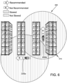
- FIG. 6 is a schematic illustration of T2T-equipped trucks 200a and 200b driving in a warehouse environment 600 according to still further principles of the present inventive concepts.
- the two T2T-equipped trucks 200a and 200b using a proximity detection and slow-down system according to principles of the present inventive concepts are operating in a warehouse environment 600 with shelving units 610.
- both vehicles are travelling in the recommended direction (indicated by the letter "R"), neither vehicle is slowed-down (indicated by vertical cross-hatching) even though they are within a restricted distance (represented by overlapping circles) of each other.
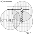
- FIG. 7 is a schematic illustration of a T2T-equipped truck 200 driving near a restricted location 710, such as a crosswalk, according to additional principles of the present inventive concepts.
- a T2T-equipped truck 200 having a proximity detection and slow-down system constructed using principles of the present inventive concepts is operating within a restricted location 710.
- the truck 200 is operating in the recommended direction (indicated by the letter "R"), the automatic slow-down function is disabled and the truck 200 can continue at normal speed (represented by vertical cross-hatching) under the operator's control.
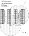
- FIG 8 is a schematic illustration of a T2T-equipped truck 200 driving in a warehouse environment 800 near a tagged pedestrian 810 according to yet other principles of the present inventive concepts.
- a T2T-equipped truck 200 using the proximity detection and slow-down system according to principles of the present inventive concepts is being operated in a warehouse environment 800.
- the truck 200 is within a restricted distance of a pedestrian 810 equipped with a UWB tag.
- the conventional system would slow the truck 200 down automatically, the system of the present inventive concepts allows the vehicle 200 to continue to operate at normal speed (indicated by vertical cross-hatching) under the operator's control because the vehicle 200 is travelling in the recommended direction (indicated by the letter "R").
- a T2T-equipped truck 200 may be able to distinguish between UWB tags associated with other trucks from UWB tags associated with pedestrians. With such distinguishing capability, a T2T-equipped truck 200 may continue to operate at normal speed when traveling in the recommended direction and within a restricted distance of another truck, but may be slowed when traveling in the recommended direction and within a restricted distance of a pedestrian. Other distinguishing capabilities may be included for UWB tags associated with intersections, cross-walks, pedestrian walkways, or other suitable areas or items where a vehicle slow-down is desired regardless of travel direction.
- the system may be enabled to detect a number of restricted items within close proximity and maintain the slow down function if the number of restricted items in close proximity exceeds a predetermined number ( e . g ., 3).
- FIG 9 is a schematic illustration of T2T-equipped trucks and a tagged pedestrian in a warehouse environment 900 utilizing an RTLS system for determining locations according to still further principles of the present inventive concepts.
- an RTLS system identifies absolute locations of tagged vehicles 200a, 200b, objects, or pedestrians 810 in real-time.
- the RTLS system could be used to identify vehicle 200a, 200b, obj ect, and pedestrian 810 locations and trigger the automatic slow-down function when a truck 200a, 200b is within a restricted distance of a tagged vehicle 200a, 200b, object, or pedestrian 810.
- the automatic slow-down function could be disabled when the truck 200a, 200b is travelling in a recommended direction.
- FIG 10 is a schematic illustration comparing OAS operation in local (e.g ., UWB) and facility-wide (e.g ., RTLS) equipped systems according to principles of the present inventive concepts.
- UWB operated systems 150 benefit from lower latency but are much more restricted in terms of the distance between objects they are able to determine.
- RTLS systems have the advantage of knowing absolute locations of all tagged objects, pedestrians, and vehicles within the facility, but suffer from longer latency times.
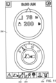
- FIG 11 is a schematic illustration of a display 250 in a T2T-equipped truck 200 according to additional principles of the present inventive concepts.
- a truck display 250 can provide information to an operator regarding the operation of the OAS system.
- this information can include visual warnings regarding proximity to other vehicles (alert symbol 252), pedestrians (alert symbol 254), restricted zones (alert symbol 256) or other objects. Audible warnings could also be provided.
- Other information regarding loads, fork height, truck speed, whether the truck 200 is driving in the recommended direction, and/or other desired information could also be communicated to the operator using the display 250.
- steer direction e . g ., whether a vehicle is travelling straight or turning
- mast height e . g ., whether the forks 210 are raised/lowered and by how much
- a load condition or other factors could be used to determine whether or not to disable the proximity-detection slow down function of the lift truck. For instance, if a truck is travelling straight, regardless of the direction of travel, the slow-down function could be disabled. Alternatively, if the forks 210 are lowered, regardless of the direction of travel, the slow-down function could be disabled. Or if the truck is unloaded, the slow-down function could be disabled regardless of the direction of travel.
- the slow-down function could be maintained if other predetermined conditions are satisfied. For example, if the truck is determined to be in close proximity to a predetermined number of restricted items (such as multiple vehicles or pedestrians, for example), the slow-down function could be maintained regardless of whether the vehicle is travelling in a recommended direction. The predetermined number could be selected and updated based on customer needs or concerns. Or the system could be configured to maintain the automatic slow-down function whenever a pedestrian (or any other user-selected restricted item) is in close proximity.
- a predetermined number of restricted items such as multiple vehicles or pedestrians, for example
Landscapes
- Engineering & Computer Science (AREA)
- Transportation (AREA)
- Mechanical Engineering (AREA)
- Automation & Control Theory (AREA)
- Structural Engineering (AREA)
- Civil Engineering (AREA)
- Life Sciences & Earth Sciences (AREA)
- Geology (AREA)
- Human Computer Interaction (AREA)
- Physics & Mathematics (AREA)
- General Physics & Mathematics (AREA)
- Radar, Positioning & Navigation (AREA)
- Remote Sensing (AREA)
- Control Of Driving Devices And Active Controlling Of Vehicle (AREA)
- Traffic Control Systems (AREA)
- Electric Propulsion And Braking For Vehicles (AREA)
Abstract
Description
- This application claims priority to
U.S. Patent Appl. No. 17/858,824, entitled "DIRECTION-OF-TRAVEL-BASED INHIBITION OF SPEED CONTROL BASED ON TRUCK-TO-TRUCK PROXIMITY DETECTION," filed July 6, 2022 - This disclosure relates generally to methods and mechanisms for sensing and responding to vehicle proximity and to implementing a slow-down function for materials-handling vehicles determined to be in close proximity to each other or other speed-restricting people, objects, or features.
- Operator assist systems (OAS) in materials-handling vehicles, such as lift trucks, can include proximity detection and slow-down systems. Proximity detection and slow-down systems have been implemented in lift trucks, for example, to slow down the vehicles whenever two or more trucks are within a predetermined distance of each other as determined using ultra-wideband (UWB) radio frequency sensors. This is referred to as "truck-to-truck" or "T2T" slow-down. The T2T slow-down feature causes trucks within close proximity of each other to slow down regardless of direction of travel and regardless of the likelihood or unlikelihood of a collision between the vehicles.
- While UWB provides a reliable and inexpensive mechanism for determining proximity between primary and secondary sensors, it also has significant limitations. Firstly, simple UWB systems (e.g., single antennae) can only sense distance, not direction, between sensors and only have a detection range of approximately 0-25 meters. Implementing directionality using UWB requires a much more advanced and expensive system. Furthermore, UWB systems may have a limited sampling frequency that restricts the ability to be used for determining accurate and complete velocity profiles. In addition, "proximity" using UWB is determined in an open "3D" environment and cannot determine vehicle travel direction, whether vehicles are on different vertical levels, or if other obstacles such as shelving or other objects are arranged between vehicles and would prevent collisions.
- Referring to
Figures 1A and1B , aconventional lift truck 100a having a T2T slow-down function slows down by restricting the maximum operating speed of thetruck 100a when anothertruck 100b is determined to be in close proximity to it. This can be done, for instance, utilizing UWB radio frequency sensors to determine the relative distance between thetrucks truck 100a down as a function of proximity to anothertruck 100b. Distance, speed, and stability issues may all be taken into account in slowing thevehicle 100a. Utilizing the conventional T2T slow-down system, theother lift truck 100b in close proximity to thefirst truck 100a is also slowed. Athird vehicle 100c is not slowed (represented by vertical cross-hatching) because it is not close enough to either of theother trucks - The vehicle slow-down occurs regardless of the direction of travel of the
lift trucks lift truck trucks - Balancing productivity and collision avoidance is a primary concern in the operation of lift trucks. The principles and concepts described herein provide a truck-proximity detection and speed-control system that is inexpensive to implement and can significantly increase productivity without sacrificing collision avoidance. One embodiment utilizes both proximity detection and readily available information regarding a vehicle's direction of travel to determine whether or not to slow the vehicle down when close to a restricted item, such as another vehicle, pedestrian, high-value object, or high-traffic location (e.g., a crosswalk, intersection, or pedestrian walk-way).
- One example embodiment can include a UWB sensor or any other relative or absolute location/distance sensor (e.g., radar, ultrasonic, stereo camera, laser rangefinder, infrared, or electromagnetic) (herein, a "proximity sensor") and an operator assist system (OAS) controller that communicates with a truck controller arranged in the lift truck, for instance, using the controller area network (CAN) specification. A proximity sensor can be any device that can detect a relative distance between itself and something else. The proximity sensor communicates with the OAS controller to determine when the truck is in close proximity to another truck, object, pedestrian, or restricted location (each, a "restricted item"). A restricted item could be anything that the customer might want to automatically slow the truck down for when it is near that item. The truck controller identifies a direction of travel of the lift truck and communicates that information to the OAS controller. The OAS controller compares the truck travel direction with a predetermined recommended direction selected by the customer and programmed into the OAS controller.
- The customer can, for example, select a recommended direction of travel based on a truck type, a load condition, an operating environment, a load type, a mast height, or any other environmental or truck conditions. The recommended direction of travel is typically the preferred direction to operate the vehicle and other directions are undesirable based on the customer's training and experience. Furthermore, the recommended direction of travel can be location based and/or determined on a truck-by-truck basis and updated in real-time during operation of the truck based on any desired factors.
- If the OAS controller determines that the truck is travelling in the recommended direction, the automatic slow-down function is disabled. If, however, the OAS controller determines that the truck is not travelling in the recommended direction, the automatic slow-down function is not disabled and, if the truck is determined to be in close proximity to another truck or restricted object or location, the automatic slow-down function is activated and the OAS controller communicates with the truck controller to set a maximum speed and slow the vehicle down if it exceeds that maximum speed. More specifically, as in the conventional system, UWB radio frequency sensors can be used to determine 2D proximity between T2T-equipped vehicles. For vehicle use, travel is generally confined to 2D movements over a surface, therefore the UWB technology will be described here as operating in 2D. However, UWB detects objects in a 3D environment and in some embodiments such 3D detection may be used. Other vehicles, trucks, pedestrians, objects, or locations can also be provided with UWB tags to indicate their distance or proximity to a T2T-equipped truck. According to principles of the concepts disclosed herein, however, in addition to the 2D UWB proximity sensors arranged in the trucks, a vehicle also uses information regarding its own direction of travel to determine whether or not to implement the slow-down function.
- According to one preferred aspect, a customer can determine a preferred or recommended direction of travel for T2T-equipped vehicles in its facility. The recommended direction of travel can be determined by the customer on a case-by-case basis, such as for a particular facility, one or more specific locations within the facility, and/or for individual trucks. The recommended direction of travel can further be selected and/or modified based on truck conditions, such as load conditions, mast conditions, speed, etc. Information regarding the recommended direction of travel can further be updated in real-time based on customer desires. In one embodiment, the recommended direction of travel can, for instance, be either a fork-leading or a fork-trailing direction.
- In one specific embodiment, a recommended direction is the
forks 210 trailing direction. If a vehicle is travelling in the recommended direction (e.g.,forks 210 trailing), the automatic slow-down function is disabled and the truck is not slowed even if it is within a restricted predetermined distance of another truck (or other speed restricting object or location). However, if the truck is not travelling in the recommended direction (e.g., is travelling with theforks 210 leading), the automatic slow-down function remains enabled and, when the proximity sensors determine that the truck is within the predetermined distance of another vehicle (or other speed restricting object or location), the automatic slow-down system slows the vehicle down to help an operator prevent a collision. - In other words, the proximity-detection and speed-control system according to some of the present inventive principles would only slow down a T2T-equipped truck if it is both being driven in the non-recommended direction and it's near another T2T-equipped truck or tagged person, object, or location. The system would not slow down a truck that is driving in the recommended direction even if it is near another sensed vehicle, object, or location and would not slow down a truck driving in the non-recommended direction that is not within a restricted distance of another speed-restricting feature.
- In other embodiments, steer direction (e.g., whether a vehicle is travelling straight or turning, mast height (e.g., whether the
forks 210 are raised/lowered and by how much), a load condition, or other factors could be used to determine whether or not to disable the proximity-detection slow down function of the lift truck. For instance, if a truck is travelling straight, regardless of the direction of travel, the slow-down function could be disabled. Alternatively, if theforks 210 are lowered, regardless of the direction of travel, the slow-down function could be disabled. Or if the truck is unloaded, the slow-down function could be disabled regardless of the direction of travel. - In still other embodiments, the slow-down function could be maintained if other predetermined conditions are satisfied. For example, if the truck is determined to be in close proximity to a predetermined number of restricted items (such as multiple vehicles or pedestrians, for example), the slow-down function could be maintained regardless of whether the vehicle is travelling in a recommended direction. The predetermined number could be selected and updated based on customer needs or concerns. Or the system could be configured to maintain the automatic slow-down function whenever a pedestrian (or any other user-selected restricted item) is in close proximity.
- Various aspects, embodiments, and configurations of the principles and concepts described herein are possible without departing from the principles disclosed herein. The inventive concepts are therefore not limited to any of the particular aspects, embodiments, or configurations shown or described herein. In addition, various features, benefits, and configurations incorporating the principles and concepts described and illustrated herein will be readily apparent to those of ordinary skill in the art based on this disclosure, and all such features, benefits and configurations are considered within the scope of the present invention.
- Among other things, it should be apparent that the proximity detection and slow-down system could be used on vehicles and other moving devices besides lift trucks. Furthermore, the system can be configured as a retrofit or original equipment for a lift truck or other vehicle or device. In addition, a Real-Time Locating System (RTLS) or other location-sensing system or systems could be used to identify truck locations and determine proximity between vehicles, pedestrians, and other speed restricting objects in addition to, or instead of, the UWB equipment and sensors.
- Additional aspects and advantages will be apparent from the following detailed description of example embodiments, which proceeds with reference to the accompanying drawings.
- The foregoing and additional objects, features, and advantages of the present inventive concepts will become more readily apparent from the following detailed description of preferred embodiments, depicted in the attached drawings, in which:
-
Figure 1A is a schematic illustration of trucks driving in a 2D open environment according to a conventional system for proximity detection slow-down in T2T-equipped lift trucks. -
Figure 1B is a schematic illustration of trucks driving in a warehouse environment according to additional features of a conventional system for proximity detection slow-down in T2T-equipped lift trucks. -
Figure 2 is a schematic illustration of T2T-equipped trucks driving in an 2D open environment according to one embodiment of the present invention. -
Figure 3A is a schematic illustration of T2T-equipped trucks driving in a warehouse environment according to one embodiment of the present invention. -
Figure 3B is a schematic illustration of T2T-equipped trucks driving in a warehouse environment according to one embodiment of the present invention. -
Figure 4 is a schematic block diagram of a proximity detection and slow-down system for lift trucks according to one embodiment of the present invention. -
Figure 5 is a flow chart illustrating a method of determining whether to initiate a slow down operation in a proximity detection and slow-down system according to one embodiment of the present invention. -
Figure 6 is a schematic illustration of T2T-equipped trucks driving in a warehouse environment according to one embodiment of the present invention. -
Figure 7 is a schematic illustration of a T2T-equipped truck driving near a restricted location according to one embodiment of the present invention. -
Figure 8 is a schematic illustration of a T2T-equipped truck driving in a warehouse environment near a tagged pedestrian according to one embodiment of the present invention. -
Figure 9 is a schematic illustration of T2T-equipped trucks and a tagged pedestrian in a warehouse environment utilizing an RTLS system for determining locations according to one embodiment of the present invention. -
Figure 10 is a schematic illustration comparing OAS operation in local (e.g., UWB) and RTLS equipped systems according to one embodiment of the present invention. -
Figure 11 is a schematic illustration of a display in a T2T-equipped truck according to one embodiment of the present invention. - Example embodiments are described below with reference to the accompanying drawings. Unless otherwise expressly stated in the drawings, the sizes, positions, etc., of components, features, elements, etc., as well as any distances therebetween, are not necessarily to scale, and may be disproportionate and/or exaggerated for clarity.
- The terminology used herein is for the purpose of describing particular example embodiments only and is not intended to be limiting. As used herein, the singular forms "a," "an" and "the" are intended to include the plural forms as well, unless the context clearly indicates otherwise. It should be recognized that the terms "comprise," "comprises," and/or "comprising," when used in this specification, specify the presence of stated features, integers, steps, operations, elements, and/or components, but do not preclude the presence or addition of one or more other features, integers, steps, operations, elements, components, and/or groups thereof. Unless otherwise specified, a range of values, when recited, includes both the upper and lower limits of the range, as well as any sub-ranges therebetween. Unless indicated otherwise, terms such as "first," "second," etc., are only used to distinguish one element from another. For example, one element could be termed a "first element" and similarly, another element could be termed a "second element," or vice versa. The section headings used herein are for organizational purposes only and are not to be construed as limiting the subject matter described.
- Unless indicated otherwise, the terms "about," "thereabout," "substantially," etc. mean that amounts, sizes, formulations, parameters, and other quantities and characteristics are not and need not be exact, but may be approximate and/or larger or smaller, as desired, reflecting tolerances, conversion factors, rounding off, measurement error and the like, and other factors known to those of skill in the art.
- Spatially relative terms, such as "right," left," "below," "beneath," "lower," "above," and "upper," and the like, may be used herein for ease of description to describe one element's or feature's relationship to another element or feature, as illustrated in the drawings. It should be recognized that the spatially relative terms are intended to encompass different orientations in addition to the orientation depicted in the figures. For example, if an object in the figures is turned over, elements described as "below" or "beneath" other elements or features would then be oriented "above" the other elements or features. Thus, the term "below" can, for example, encompass both an orientation of above and below. An object may be otherwise oriented (e.g., rotated 90 degrees or at other orientations) and the spatially relative descriptors used herein may be interpreted accordingly.
- Unless clearly indicated otherwise, all connections and all operative connections may be direct or indirect. Similarly, unless clearly indicated otherwise, all connections and all operative connections may be rigid or non-rigid.
- Like numbers refer to like elements throughout. Thus, the same or similar numbers may be described with reference to other drawings even if they are neither mentioned nor described in the corresponding drawing. Also, even elements that are not denoted by reference numbers may be described with reference to other drawings.
- Many different forms and embodiments are possible without deviating from the spirit and teachings of this disclosure and so this disclosure should not be construed as limited to the example embodiments set forth herein. Rather, these example embodiments are provided so that this disclosure will be thorough and complete and will convey the scope of the disclosure to those skilled in the art.
- As explained above, balancing productivity and collision avoidance is a primary concern in the operation of lift trucks. Conventional systems prioritize collision avoidance at a significant cost to productivity. As shown in
Figures 1A and1B , for example, even though bothtrucks trucks third truck 100c travelling in the recommended direction is not slowed (indicated by the vertical cross-hatching) because it is not in close enough proximity to theother trucks - Unfortunately, this conventional system, while successful in helping to avoid collisions, can reduce productivity by causing vehicle slow-downs in situations where collisions between vehicles are unlikely to occur or impossible. Referring specifically to
Figure 1B , for example,trucks trucks - The truck proximity-detection and speed-control system according to principles of the present inventive concepts is both inexpensive to implement and can significantly increase productivity without unduly sacrificing collision avoidance. As explained in further detail below, a preferred embodiment utilizes both proximity detection and readily available information regarding a vehicle's direction of travel to determine whether or not to slow the vehicle down when close to a restricted item (e.g., another vehicle, pedestrian, high-value object, or high-traffic location (e.g., a crosswalk, intersection, or pedestrian walk-way)).
-
Figures 2-7 illustrate operation of a proximity detection slow-down function according to principles of the present inventive concepts. Specifically, referring toFigures 2-7 , as in the conventional system, UWB radio frequency emitters are provided onlift trucks travel zones 400, and other restricted objects or locations. These UWB emitters provide a zone around a vehicle or other tagged person, object, or location that identifies its location to a T2T-equipped truck. This zone is represented bycircles - In addition to the conventional UWB emitters and sensors, however, a T2T-equipped vehicle according to principles of the present inventive concepts also uses information regarding its own direction of travel to determine whether or not to implement the slow-down function. According to one preferred aspect, a customer can determine a preferred or recommended direction of travel for T2T-equipped vehicles in its facility. The recommended direction of travel can be determined by the customer on a case-by-case basis, such as for a particular facility, one or more specific locations within the facility, for individual trucks, or even based on truck conditions. Information regarding the recommended direction of travel can further be updated in real-time based on customer desires. The recommended direction of travel can, for instance, be either a fork-leading or a fork-trailing direction. In the embodiments shown, the selected recommended direction of travel is the fork trailing direction.
- According to the inventive principles, if a vehicle is travelling in a recommended direction (e.g.,
forks 210 trailing), the automatic slow-down function is disabled and the T2T-equippedtruck truck forks 210 leading), the automatic slow-down function remains enabled and when the proximity sensors determine that thetruck - In other words, the proximity-detection and speed-control system according to present inventive principles would only slow down a T2T-equipped truck if it's both being driven in the non-recommended direction and it is near another T2T-equipped truck or tagged person, object, or location. The system would not slow down a truck that is driving in the recommended direction even if it is near another sensed vehicle, object, or location and would not slow down a truck driving in the non-recommended direction that is not within a restricted distance of another speed restricting feature.
- Referring specifically to
Figures 2-3B , the principles and concepts described herein provide a truck proximity-detection and speed-control system that utilizes both proximity detection and information regarding a vehicle's direction of travel to determine whether or not to slow the vehicle down. - More particularly, in addition to the 2D proximity sensors arranged in the
trucks trucks vehicle forks 210 trailing). If thevehicle truck truck truck forks 210 leading (indicated by the letter "N")), the automatic slow-down function remains enabled and when the proximity sensors indicate that thetruck vehicle - The automatic slow-down feature can, for instance, be implemented using the vehicle's regen function (for electric vehicles) or other vehicle controls (friction brakes, transmission, coast control, etc.) to limit a maximum speed of the
truck - In other embodiments, an RTLS could supplement or replace the UWB emitters and sensors to determine proximity between vehicles, pedestrians, and other objects or locations. In a still further embodiment, one or more additional sensors, such as LIDAR or other sensors could also be used to supplement or supplant the information obtained from 2D proximity sensors, and to make a more informed decision on whether or not to slow the vehicle down. The information from other sensors could also be used to determine how much and how quickly to slow the vehicle down. Furthermore, any type of proximity sensor could be used to make the proximity determination.
- To increase productivity, the proximity-detection and speed-control system of the present inventive principles would only slow down a
truck truck truck truck truck truck - However, the system could identify areas, zones, high-priority assets or other features (such as pedestrians) that require slow-down of all vehicles regardless of recommended or non-recommended travel direction. In these areas, the T2T slow-down system could remain active regardless of a direction of travel of the vehicle. Alternatively, or additionally, the T2T slow-down system may slow a vehicle traveling in the recommended direction if a predetermined number of trucks or other restricted items are nearby. For example, a truck traveling in the recommended direction may not be slowed by the T2T system if one or two restricted items are nearby, but may be slowed if three or more restricted items are nearby.
-
Figure 4 is a schematic block diagram illustrating a proximity-detection and slow-downsystem 400 for alift truck 200 according to principles of the present inventive concepts. Referring additionally toFigure 4 , aproximity sensor 410 and anOAS controller 420 are provided. TheOAS controller 420 communicates with atruck controller 220 arranged in thelift truck 200, for instance, using the CAN specification. Thelocation sensor 410 communicates with theOAS controller 420 to signal when the truck is in close proximity to another truck, object, pedestrian or restricted location (e.g., a "restricted item"). Thetruck controller 220 identifies a direction of travel of the lift truck and communicates that information to theOAS controller 420. TheOAS controller 420 compares the truck travel direction with a predetermined recommended direction selected by the customer. If theOAS controller 420 determines that thetruck 200 is travelling in the recommended direction, the automatic slow-down function is disabled. If, however, theOAS controller 420 determines that thetruck 200 is not travelling in the recommended direction, the automatic slow-down function is not disabled and, if thetruck 200 is determined to be in close proximity to another truck or restricted object or location using thesensor 410, the automatic slow-down function is activated and theOAS controller 420 communicates with thetruck controller 220 to set a maximum speed and slow thevehicle 200 down if it exceeds that maximum speed. Speed control can be accomplished, for example, using a regen system of theelectric vehicle 200. Alternatively, or in addition, speed control could be accomplished using friction brakes, down-shifting the vehicle's transmission, coasting down, or any other method of slowing the vehicle. - In one embodiment, a proximity detection and slow-down
system 400 for alift truck 200 includes aUWB sensor 410 and acontroller 420, such as those available through Litum Technologies, Inc. Thecontroller 420 can communicate with atruck controller 220 in thelift truck 200 through the truck's controller area network (CAN)bus 230. In operation, thecontroller 420 can receive information from the truck'scontroller 220 regarding the vehicle's direction of travel. Thesystem controller 420 can also receive information from theUWB sensor 410 regarding whether any UWB equipped vehicles, objects, pedestrians, or other tagged objects or locations are within a restricted distance of thevehicle 200. If thevehicle 200 is travelling in a non-recommended direction and theUWB sensor 410 indicates a tagged object or vehicle is within the restricted distance, thecontroller 420 communicates with thetruck controller 220 through theCAN bus 230 to set a maximum speed and slow thetruck 200 down if it exceeds the maximum speed. -
Figure 5 is a flowchart illustrating a method for determining whether to slow down a vehicle using the proximity-detection and speed-control system of the present inventive concepts. Referring additionally toFigure 4 , the method determines in afirst step 410 whether thevehicle vehicle step 430 and thevehicle vehicle vehicle second step 420 determines if thevehicle vehicle step 440 and the vehicle is slowed. Instep 450, if, however, the vehicle is not near another vehicle (or other restricted item), the vehicle continues at normal speed, or, if it had been previously slowed due to proximity to another vehicle (or other restricted item), it resumes normal speed as soon as it is no longer within the restricted proximity. -
Figure 6 is a schematic illustration of T2T-equippedtrucks warehouse environment 600 according to still further principles of the present inventive concepts. The two T2T-equippedtrucks warehouse environment 600 withshelving units 610. As illustrated inFigure 6 , because both vehicles are travelling in the recommended direction (indicated by the letter "R"), neither vehicle is slowed-down (indicated by vertical cross-hatching) even though they are within a restricted distance (represented by overlapping circles) of each other. -
Figure 7 is a schematic illustration of a T2T-equippedtruck 200 driving near a restrictedlocation 710, such as a crosswalk, according to additional principles of the present inventive concepts. Referring specifically toFigure 7 , a T2T-equippedtruck 200 having a proximity detection and slow-down system constructed using principles of the present inventive concepts is operating within a restrictedlocation 710. However, because thetruck 200 is operating in the recommended direction (indicated by the letter "R"), the automatic slow-down function is disabled and thetruck 200 can continue at normal speed (represented by vertical cross-hatching) under the operator's control. -
Figure 8 is a schematic illustration of a T2T-equippedtruck 200 driving in awarehouse environment 800 near a taggedpedestrian 810 according to yet other principles of the present inventive concepts. Referring specifically toFigure 8 , a T2T-equippedtruck 200 using the proximity detection and slow-down system according to principles of the present inventive concepts is being operated in awarehouse environment 800. As shown, thetruck 200 is within a restricted distance of apedestrian 810 equipped with a UWB tag. Although the conventional system would slow thetruck 200 down automatically, the system of the present inventive concepts allows thevehicle 200 to continue to operate at normal speed (indicated by vertical cross-hatching) under the operator's control because thevehicle 200 is travelling in the recommended direction (indicated by the letter "R").
Alternately, or in addition, a T2T-equippedtruck 200 may be able to distinguish between UWB tags associated with other trucks from UWB tags associated with pedestrians. With such distinguishing capability, a T2T-equippedtruck 200 may continue to operate at normal speed when traveling in the recommended direction and within a restricted distance of another truck, but may be slowed when traveling in the recommended direction and within a restricted distance of a pedestrian. Other distinguishing capabilities may be included for UWB tags associated with intersections, cross-walks, pedestrian walkways, or other suitable areas or items where a vehicle slow-down is desired regardless of travel direction. In addition, the system may be enabled to detect a number of restricted items within close proximity and maintain the slow down function if the number of restricted items in close proximity exceeds a predetermined number (e.g., 3). -
Figure 9 is a schematic illustration of T2T-equipped trucks and a tagged pedestrian in awarehouse environment 900 utilizing an RTLS system for determining locations according to still further principles of the present inventive concepts. Referring specifically toFigure 9 , an RTLS system identifies absolute locations of taggedvehicles pedestrians 810 in real-time. As an alternative (or supplement) to the UWB sensing system explained previously, the RTLS system could be used to identifyvehicle pedestrian 810 locations and trigger the automatic slow-down function when atruck vehicle pedestrian 810. According to principles of the present inventive concepts, however, the automatic slow-down function could be disabled when thetruck -
Figure 10 is a schematic illustration comparing OAS operation in local (e.g., UWB) and facility-wide (e.g., RTLS) equipped systems according to principles of the present inventive concepts. Referring additionally toFigure 10 , UWB operatedsystems 150 benefit from lower latency but are much more restricted in terms of the distance between objects they are able to determine. RTLS systems have the advantage of knowing absolute locations of all tagged objects, pedestrians, and vehicles within the facility, but suffer from longer latency times. -
Figure 11 is a schematic illustration of adisplay 250 in a T2T-equippedtruck 200 according to additional principles of the present inventive concepts. Referring specifically toFigure 11 , atruck display 250 can provide information to an operator regarding the operation of the OAS system. Among other things, this information can include visual warnings regarding proximity to other vehicles (alert symbol 252), pedestrians (alert symbol 254), restricted zones (alert symbol 256) or other objects. Audible warnings could also be provided. Other information regarding loads, fork height, truck speed, whether thetruck 200 is driving in the recommended direction, and/or other desired information could also be communicated to the operator using thedisplay 250. - In other embodiments, steer direction (e.g., whether a vehicle is travelling straight or turning, mast height (e.g., whether the
forks 210 are raised/lowered and by how much), a load condition, or other factors could be used to determine whether or not to disable the proximity-detection slow down function of the lift truck. For instance, if a truck is travelling straight, regardless of the direction of travel, the slow-down function could be disabled. Alternatively, if theforks 210 are lowered, regardless of the direction of travel, the slow-down function could be disabled. Or if the truck is unloaded, the slow-down function could be disabled regardless of the direction of travel. - In still other embodiments, the slow-down function could be maintained if other predetermined conditions are satisfied. For example, if the truck is determined to be in close proximity to a predetermined number of restricted items (such as multiple vehicles or pedestrians, for example), the slow-down function could be maintained regardless of whether the vehicle is travelling in a recommended direction. The predetermined number could be selected and updated based on customer needs or concerns. Or the system could be configured to maintain the automatic slow-down function whenever a pedestrian (or any other user-selected restricted item) is in close proximity.
- Various other improvements are also contemplated and numerous variations to the specific designs identified above are possible without departing from the spirit and scope of the inventive concepts. Having described and illustrated principles of the present inventive concepts in various preferred embodiments thereof, it should be apparent that the invention can be modified in arrangement and detail without departing from such principles. In particular, it should be apparent that the systems and methods described herein could be used for vehicles other than lift trucks and for other moving devices.
- The terms and descriptions used above are set forth by way of illustration and example only and are not meant as limitations. Those skilled in the art will recognize that many variations, enhancements and modifications of the concepts described herein are possible without departing from the underlying principles of the invention. For example, skilled persons will appreciate that the subject matter of any sentence or paragraph can be combined with subject matter of some or all of the other sentences or paragraphs, except where such combinations are mutually exclusive. The scope of the invention should therefore be determined only by the following claims, claims presented in a continuation patent application, and equivalents to the foregoing claims.
- In the following further embodiments of the invention are disclosed:
- 1. A proximity-detection speed-control system (400) for restricting a speed of a materials-handling vehicle (200a), the system comprising:
- a proximity sensor (410) for determining a proximity of the vehicle (200a) to another vehicle (200b) or to a restricted object (610), person (810), or location (710);
- a recommended direction of travel (R) for the vehicle (200a) that is selectable by a user as either a forward or a reverse direction;
- a controller (220) configured to identify a current direction of travel of the vehicle (200a) and to determine whether the vehicle (200a) is travelling in the recommended direction of travel (R); and
- a speed controller (420) configured to automatically restrict the vehicle's speed if the proximity sensor (410) determines that the vehicle (200a) is within a predetermined distance of another
vehicle 200b or restricted object (610), person (810), or location (710), and the controller (220) identifies the vehicle (200a) as not travelling in the recommended direction of travel (R).
- 2. A proximity-detection speed-control system (400) according to embodiment 1, wherein the speed controller (420) is disabled if the vehicle (200a) is travelling in the recommended direction of travel (R).
- 3. A proximity-detection speed-control system (400) according to one of the embodiments 1 or 2, wherein the recommended direction of travel (R) is user-selected based on one or more factors selected from the group comprising: a vehicle type, a load condition, an operating environment, a load type, a mast height, and a vehicle (200a) location.
- 4. A proximity-detection speed-control system (400) according to one of the embodiments 1 to 3, wherein the recommended direction of travel (R) can be changed by the user during operation of the vehicle (200a).
- 5. A proximity-detection speed-control system (400) according to embodiment 4, wherein the recommended direction of travel (R) is updated in real-time during operation of the vehicle (200a).
- 6. A proximity-detection speed-control system (400) according to
embodiment 5, wherein the recommended direction of travel (R) changes depending on a load condition. - 7. A proximity-detection speed-control system (400) according to one of the embodiments 1 to 6, wherein an initial recommended direction of travel (R) is selected based on a vehicle (200a) type and an
operating environment 600. - 8. A proximity-detection speed-control system (400) according to one of the embodiments 1 to 7, wherein the proximity sensor (410) comprises an ultra-wideband (UWB) sensor (410).
- 9. A proximity-detection speed-control system (400) according to one of the embodiments 1 to 8, wherein the recommended direction of travel (R) changes depending on a location of the vehicle (200a).
- 10. A proximity-detection speed-control system (400) according to one of the embodiments 1 to 9, wherein the recommended direction of travel (R) is either a fork-leading or a fork-trailing direction selected based on user preference.
- 11. A method for automatically speed restricting a materials-handling vehicle (200a), the method comprising:
- receiving a recommended direction of travel (R) of the vehicle (200a) selected between a forward and a reverse direction based on customer preferences;
- determining a direction of travel of the vehicle (200a) in relation to the selected recommended direction of travel (R);
- sensing the vehicle's proximity to a restricted vehicle (200b), object (610), person (810), or location (710); and
- speed restricting the vehicle (200a) only if the vehicle (200a) is not travelling in the selected recommended direction of travel (R) and the vehicle (200a) is within a predetermined distance of a restricted vehicle (200b), object (610), person (810), or location (710).
- 12. A method according to embodiment 11, wherein a UWB sensor (410) is used to determine whether the vehicle (200a) is within the predetermined distance of a restricted vehicle (200b), object (610), person (810), or location (710).
- 13. A method according to one of the embodiments 11 or 12, wherein the selected recommended direction of travel (R) is changeable by a customer during operation of the vehicle (200a).
- 14. A method according to embodiment 13, wherein the recommended direction of travel (R) is modified during vehicle (200a) operation based on one or more factors selected from the group comprising: a load condition, an operating environment, a load type, a mast height, and a vehicle (200a) location.
- 15. A method according to one of the embodiment 11 to 14, further comprising:
receiving, in real-time, a change to the recommended direction of travel (R).
Claims (15)
- A proximity-detection speed-control system (400) for restricting a speed of a materials-handling vehicle (200a), the system comprising:a proximity sensor (410) for determining a proximity of the vehicle (200a) to another vehicle (200b) or to a restricted object (610), person (810) or location (710);a recommended direction of travel (R) for the vehicle (200a) that is selectable by a user as either a forward or a reverse direction;a controller (220) configured to identify information related to operation of the vehicle, wherein said information comprises one or more of:a current direction of travel of the vehicle (200a),a steer direction of the vehicle (200a),a load condition of the vehicle (200a),and a mast height of the vehicle (200a),wherein the controller (220) is further configured to determine whether the vehicle (200a) is travelling in the recommended direction of travel (R); anda speed controller (420) configured to automatically implement a slow-down function to restrict the vehicle's speed if the proximity sensor (410) determines that the vehicle (200a) is within a predetermined distance of another vehicle (200b) or restricted object (610), person (810), or location (710), and the controller (220) identifies the vehicle (200a) as not travelling in the recommended direction of travel (R), unless other information identified by the controller (220) is used to disable the slow-down function.
- A proximity-detection speed-control system (400) according to claim 1, wherein the speed controller (420) is disabled if any one or more of the following disabling conditions are satisfied:the vehicle (200a) is travelling in the recommended direction of travel (R),the vehicle (200a) is travelling straight,the vehicle (200a) is unloaded, orforks of the vehicle (200a) are lowered.
- A proximity-detection speed-control system (400) according to claim 2, wherein the speed controller is not disabled regardless of any of the disabling conditions being satisfied if the vehicle (200a) is determined to be within a predetermined distance of a predetermined number of other vehicles (200b), restricted objects (610), persons (810), or if the vehicle is in a restricted location (710).
- A proximity-detection speed-control system (400) according to claim 2 or 3, wherein the speed controller (420) is not disabled regardless of any of the disabling conditions being satisfied if the vehicle is within a predetermined distance of one or more persons (810).
- A proximity-detection speed control system (400) according to claim 1, 2, or 3 wherein the speed controller (420) is configured to automatically implement a slow-down function to restrict the vehicle's speed regardless of any other condition being met if the proximity sensor (410) determines that the vehicle (200a) is in a restricted location (710) or if a predetermined number of other restricted items (200b), (610), (810) are within a predetermined distance.
- A proximity-detection speed-control system (400) according to claim 3, 4, or 5, wherein the predetermined number can be selected and updated by a user.
- A proximity-detection speed-control system (400) according to claim 1, 2, 3, 4, 5, or 6 wherein the recommended direction of travel (R) is updated in real-time during operation of the vehicle (200a).
- A proximity-detection speed-control system (400) according to claim 1, 2, 3, 4, 5, 6 or 7 wherein an initial recommended direction of travel (R) is selected based on a vehicle (200a) type and an operating environment (600).
- A proximity-detection speed-control system (400) according to claim 1, 2, 3, 4, 5, 6, 7, or 8 wherein the recommended direction of travel (R) changes depending on a location of the vehicle (200a).
- A proximity-detection speed-control system (400) according to claim 1, 2, 3, 4, 5, 6, 7, 8, or 9 wherein the recommended direction of travel (R) is either a fork-leading or a fork-trailing direction selected based on user preference.
- A method for automatically speed restricting a materials-handling vehicle (200a), the method comprising:receiving a recommended direction of travel (R) of the vehicle (200a) selected between a forward and a reverse direction based on customer preferences;determining a direction of travel of the vehicle (200a) in relation to the selected recommended direction of travel (R);gathering additional information related to the vehicle (200a) operation, said additional information comprising one or more of:a steer direction of the vehicle (200a);a load condition of the vehicle (200a); anda mast height of the vehicle (200a);sensing the vehicle's proximity to a restricted vehicle (200b), object (610), person (810), or location (710); andspeed restricting the vehicle (200a) using a slow-down function if the vehicle (200a) is not travelling in the selected recommended direction of travel (R) and the vehicle (200a) is within a predetermined distance of a restricted vehicle (200b), object (610), person (810), or location (710), unless the additional information identified by the controller (220) is used to disable the slow-down function.
- A method according to claim 11, wherein the slow-down function is disabled if any one or more of the following disabling conditions are satisfied:the vehicle (200a) is travelling in the recommended direction of travel (R),the vehicle (200a) is travelling straight,the vehicle (200a) is unloaded, orforks of the vehicle (200a) are lowered.
- A method according to claim 12, wherein the slow-down function is not disabled regardless of any of the disabling conditions being satisfied if the vehicle (200a) is determined to be within a predetermined distance of a predetermined number of other vehicles (200b), restricted objects (610), persons (810), or if the vehicle is in a restricted location (710).
- A method according to claim 13 wherein the predetermined number can be selected and updated by a user.
- A method according to claim 11, 12, 13, or 14, wherein the recommended direction of travel (R) is modified during vehicle (200a) operation based on one or more factors selected from the group comprising: a load condition, an operating environment, a load type, a mast height, and a vehicle 200a location.
Applications Claiming Priority (2)
| Application Number | Priority Date | Filing Date | Title |
|---|---|---|---|
| US17/858,824 US11661060B1 (en) | 2022-07-06 | 2022-07-06 | Direction-of-travel-based inhibition of speed control based on truck-to-truck proximity detection |
| EP23165389.0A EP4303171B1 (en) | 2022-07-06 | 2023-03-30 | Direction-of-travel-based inhibition of speed control based on truck-to-truck proximity detection |
Related Parent Applications (2)
| Application Number | Title | Priority Date | Filing Date |
|---|---|---|---|
| EP23165389.0A Division EP4303171B1 (en) | 2022-07-06 | 2023-03-30 | Direction-of-travel-based inhibition of speed control based on truck-to-truck proximity detection |
| EP23165389.0A Division-Into EP4303171B1 (en) | 2022-07-06 | 2023-03-30 | Direction-of-travel-based inhibition of speed control based on truck-to-truck proximity detection |
Publications (3)
| Publication Number | Publication Date |
|---|---|
| EP4509458A2 true EP4509458A2 (en) | 2025-02-19 |
| EP4509458A3 EP4509458A3 (en) | 2025-03-19 |
| EP4509458B1 EP4509458B1 (en) | 2026-01-21 |
Family
ID=85792237
Family Applications (2)
| Application Number | Title | Priority Date | Filing Date |
|---|---|---|---|
| EP24212769.4A Active EP4509458B1 (en) | 2022-07-06 | 2023-03-30 | Direction-of-travel-based inhibition of speed control based on truck-to-truck proximity detection |
| EP23165389.0A Active EP4303171B1 (en) | 2022-07-06 | 2023-03-30 | Direction-of-travel-based inhibition of speed control based on truck-to-truck proximity detection |
Family Applications After (1)
| Application Number | Title | Priority Date | Filing Date |
|---|---|---|---|
| EP23165389.0A Active EP4303171B1 (en) | 2022-07-06 | 2023-03-30 | Direction-of-travel-based inhibition of speed control based on truck-to-truck proximity detection |
Country Status (3)
| Country | Link |
|---|---|
| US (1) | US11661060B1 (en) |
| EP (2) | EP4509458B1 (en) |
| CN (1) | CN117360499A (en) |
Family Cites Families (14)
| Publication number | Priority date | Publication date | Assignee | Title |
|---|---|---|---|---|
| US8346468B2 (en) | 2008-07-08 | 2013-01-01 | Sky-Trax Incorporated | Method and apparatus for collision avoidance |
| KR101246280B1 (en) | 2008-09-26 | 2013-03-22 | 무라다기카이가부시끼가이샤 | Conveyor system |
| US8812227B2 (en) | 2011-05-19 | 2014-08-19 | Metrom Rail, Llc | Collision avoidance system for rail line vehicles |
| US10062285B2 (en) | 2012-12-21 | 2018-08-28 | Sfara, Inc. | System and method for smartphone communication during vehicle mode |
| JP2014147168A (en) * | 2013-01-28 | 2014-08-14 | Toyota Industries Corp | Vehicle speed limiting method during evacuation and vehicle |
| US10399495B1 (en) | 2014-09-05 | 2019-09-03 | United Services Automobile Association (Usaa) | Systems and methods for indicating proximity conditions for a vehicle |
| EP3118152B1 (en) | 2015-07-17 | 2018-12-05 | STILL GmbH | Method for controlling the speed of a picking industrial truck |
| US9481300B1 (en) | 2015-11-05 | 2016-11-01 | Christopher A. Lutawan | Proximity alert system |
| US20180143312A1 (en) * | 2016-11-21 | 2018-05-24 | Wal-Mart Stores, Inc. | System and method for ultra wideband signal usage with autonomous vehicles in buildings |
| CN110621567B (en) * | 2017-04-03 | 2022-09-16 | 海斯特-耶鲁集团有限公司 | Vehicle sensor systems, assemblies, and methods |
| DE102018211796A1 (en) | 2018-07-16 | 2020-01-16 | Siemens Aktiengesellschaft | Method for preventing a collision between an autonomous vehicle and a user in a range of motion of the autonomous vehicle, and system |
| DE102018129732A1 (en) | 2018-11-26 | 2020-05-28 | Beckhoff Automation Gmbh | Device and method for avoiding a collision when driving at least two movers on a drive surface |
| JP2020160914A (en) * | 2019-03-27 | 2020-10-01 | 株式会社豊田自動織機 | Object detector |
| JP7552101B2 (en) * | 2020-07-01 | 2024-09-18 | 株式会社豊田自動織機 | Industrial Vehicles |
-
2022
- 2022-07-06 US US17/858,824 patent/US11661060B1/en active Active
-
2023
- 2023-03-30 EP EP24212769.4A patent/EP4509458B1/en active Active
- 2023-03-30 EP EP23165389.0A patent/EP4303171B1/en active Active
- 2023-04-07 CN CN202310369503.5A patent/CN117360499A/en active Pending
Also Published As
| Publication number | Publication date |
|---|---|
| EP4509458B1 (en) | 2026-01-21 |
| US11661060B1 (en) | 2023-05-30 |
| CN117360499A (en) | 2024-01-09 |
| EP4303171B1 (en) | 2025-04-16 |
| EP4303171A1 (en) | 2024-01-10 |
| EP4509458A3 (en) | 2025-03-19 |
Similar Documents
| Publication | Publication Date | Title |
|---|---|---|
| US12017677B2 (en) | Sensing method, intelligent control device and autonomous driving vehicle | |
| US20190308625A1 (en) | Vehicle control device | |
| US6559761B1 (en) | Display system for vehicle environment awareness | |
| JP4883248B2 (en) | Vehicle periphery monitoring device | |
| US10471970B2 (en) | Safety apparatus for vehicle and method of using the same | |
| EP2625083B1 (en) | Zone driving | |
| KR101338246B1 (en) | Collision prevention system of mobile robot in unknown environment and method thereof | |
| JP2022539149A (en) | remote vehicle guidance | |
| JP2023174676A (en) | Vehicle display control device, method and program | |
| CN112313663A (en) | Occlusion aware planning | |
| US20200062244A1 (en) | Vehicle control device | |
| GB2547082A (en) | Vehicle turn signal detection | |
| US11766971B2 (en) | Method and apparatus for operating a camera-monitor system for a motor vehicle | |
| JP7339960B2 (en) | Using Discomfort for Autonomous Vehicle Speed Planning | |
| US10464473B2 (en) | Vehicle display system having a rationale indicator | |
| US20190033443A1 (en) | Monitoring device and monitoring method | |
| JP2019513219A (en) | Vehicle radar system | |
| KR20230136821A (en) | Advanced Driver Assistance System, and Vehicle having the same | |
| US20210122369A1 (en) | Extensiview and adaptive lka for adas and autonomous driving | |
| EP4509458A2 (en) | Direction-of-travel-based inhibition of speed control based on truck-to-truck proximity detection | |
| JP2004224093A (en) | Automatic vehicle speed control device | |
| KR20240020421A (en) | Forward collision-avoidance assist system and method thereof | |
| AU2011312938B2 (en) | Method and system for warning of objects in the vicinity of a motor vehicle | |
| KR20210046100A (en) | Apparatus for controlling autonomous parking and method thereof | |
| US20240217581A1 (en) | Vehicle Lane Control System |
Legal Events
| Date | Code | Title | Description |
|---|---|---|---|
| PUAI | Public reference made under article 153(3) epc to a published international application that has entered the european phase |
Free format text: ORIGINAL CODE: 0009012 |
|
| STAA | Information on the status of an ep patent application or granted ep patent |
Free format text: STATUS: THE APPLICATION HAS BEEN PUBLISHED |
|
| PUAL | Search report despatched |
Free format text: ORIGINAL CODE: 0009013 |
|
| AC | Divisional application: reference to earlier application |
Ref document number: 4303171 Country of ref document: EP Kind code of ref document: P |
|
| AK | Designated contracting states |
Kind code of ref document: A2 Designated state(s): AL AT BE BG CH CY CZ DE DK EE ES FI FR GB GR HR HU IE IS IT LI LT LU LV MC ME MK MT NL NO PL PT RO RS SE SI SK SM TR |
|
| AK | Designated contracting states |
Kind code of ref document: A3 Designated state(s): AL AT BE BG CH CY CZ DE DK EE ES FI FR GB GR HR HU IE IS IT LI LT LU LV MC ME MK MT NL NO PL PT RO RS SE SI SK SM TR |
|
| RIC1 | Information provided on ipc code assigned before grant |
Ipc: B66F 9/075 20060101AFI20250213BHEP |
|
| STAA | Information on the status of an ep patent application or granted ep patent |
Free format text: STATUS: REQUEST FOR EXAMINATION WAS MADE |
|
| 17P | Request for examination filed |
Effective date: 20250430 |
|
| GRAP | Despatch of communication of intention to grant a patent |
Free format text: ORIGINAL CODE: EPIDOSNIGR1 |
|
| STAA | Information on the status of an ep patent application or granted ep patent |
Free format text: STATUS: GRANT OF PATENT IS INTENDED |
|
| INTG | Intention to grant announced |
Effective date: 20250605 |
|
| GRAJ | Information related to disapproval of communication of intention to grant by the applicant or resumption of examination proceedings by the epo deleted |
Free format text: ORIGINAL CODE: EPIDOSDIGR1 |
|
| STAA | Information on the status of an ep patent application or granted ep patent |
Free format text: STATUS: REQUEST FOR EXAMINATION WAS MADE |
|
| GRAP | Despatch of communication of intention to grant a patent |
Free format text: ORIGINAL CODE: EPIDOSNIGR1 |
|
| STAA | Information on the status of an ep patent application or granted ep patent |
Free format text: STATUS: GRANT OF PATENT IS INTENDED |
|
| INTC | Intention to grant announced (deleted) | ||
| INTG | Intention to grant announced |
Effective date: 20251021 |
|
| GRAS | Grant fee paid |
Free format text: ORIGINAL CODE: EPIDOSNIGR3 |
|
| GRAA | (expected) grant |
Free format text: ORIGINAL CODE: 0009210 |
|
| STAA | Information on the status of an ep patent application or granted ep patent |
Free format text: STATUS: THE PATENT HAS BEEN GRANTED |
|
| AC | Divisional application: reference to earlier application |
Ref document number: 4303171 Country of ref document: EP Kind code of ref document: P |
|
| AK | Designated contracting states |
Kind code of ref document: B1 Designated state(s): AL AT BE BG CH CY CZ DE DK EE ES FI FR GB GR HR HU IE IS IT LI LT LU LV MC ME MK MT NL NO PL PT RO RS SE SI SK SM TR |
|
| REG | Reference to a national code |
Ref country code: CH Ref legal event code: F10 Free format text: ST27 STATUS EVENT CODE: U-0-0-F10-F00 (AS PROVIDED BY THE NATIONAL OFFICE) Effective date: 20260121 |
|
| REG | Reference to a national code |
Ref country code: DE Ref legal event code: R096 Ref document number: 602023011123 Country of ref document: DE |
|
| REG | Reference to a national code |
Ref country code: IE Ref legal event code: FG4D |
|
| PGFP | Annual fee paid to national office [announced via postgrant information from national office to epo] |
Ref country code: DE Payment date: 20260219 Year of fee payment: 4 |
|
| PGFP | Annual fee paid to national office [announced via postgrant information from national office to epo] |
Ref country code: AT Payment date: 20260301 Year of fee payment: 4 |
|
| PGFP | Annual fee paid to national office [announced via postgrant information from national office to epo] |
Ref country code: FR Payment date: 20260218 Year of fee payment: 4 |