EP4509415A1 - Labelling machine configured for labelling containers by means of partial labels by sliding application - Google Patents
Labelling machine configured for labelling containers by means of partial labels by sliding application Download PDFInfo
- Publication number
- EP4509415A1 EP4509415A1 EP23191679.2A EP23191679A EP4509415A1 EP 4509415 A1 EP4509415 A1 EP 4509415A1 EP 23191679 A EP23191679 A EP 23191679A EP 4509415 A1 EP4509415 A1 EP 4509415A1
- Authority
- EP
- European Patent Office
- Prior art keywords
- container
- pad
- label
- labelling
- trailing
- Prior art date
- Legal status (The legal status is an assumption and is not a legal conclusion. Google has not performed a legal analysis and makes no representation as to the accuracy of the status listed.)
- Pending
Links
Images



Classifications
-
- B—PERFORMING OPERATIONS; TRANSPORTING
- B65—CONVEYING; PACKING; STORING; HANDLING THIN OR FILAMENTARY MATERIAL
- B65C—LABELLING OR TAGGING MACHINES, APPARATUS, OR PROCESSES
- B65C9/00—Details of labelling machines or apparatus
- B65C9/08—Label feeding
- B65C9/18—Label feeding from strips, e.g. from rolls
- B65C9/1803—Label feeding from strips, e.g. from rolls the labels being cut from a strip
- B65C9/1815—Label feeding from strips, e.g. from rolls the labels being cut from a strip and transferred by suction means
- B65C9/1819—Label feeding from strips, e.g. from rolls the labels being cut from a strip and transferred by suction means the suction means being a vacuum drum
-
- B—PERFORMING OPERATIONS; TRANSPORTING
- B65—CONVEYING; PACKING; STORING; HANDLING THIN OR FILAMENTARY MATERIAL
- B65C—LABELLING OR TAGGING MACHINES, APPARATUS, OR PROCESSES
- B65C3/00—Labelling other than flat surfaces
- B65C3/06—Affixing labels to short rigid containers
- B65C3/08—Affixing labels to short rigid containers to container bodies
- B65C3/14—Affixing labels to short rigid containers to container bodies the container being positioned for labelling with its centre-line vertical
- B65C3/16—Affixing labels to short rigid containers to container bodies the container being positioned for labelling with its centre-line vertical by rolling the labels onto cylindrical containers, e.g. bottles
-
- B—PERFORMING OPERATIONS; TRANSPORTING
- B65—CONVEYING; PACKING; STORING; HANDLING THIN OR FILAMENTARY MATERIAL
- B65C—LABELLING OR TAGGING MACHINES, APPARATUS, OR PROCESSES
- B65C9/00—Details of labelling machines or apparatus
- B65C9/02—Devices for moving articles, e.g. containers, past labelling station
- B65C9/04—Devices for moving articles, e.g. containers, past labelling station having means for rotating the articles
-
- B—PERFORMING OPERATIONS; TRANSPORTING
- B65—CONVEYING; PACKING; STORING; HANDLING THIN OR FILAMENTARY MATERIAL
- B65C—LABELLING OR TAGGING MACHINES, APPARATUS, OR PROCESSES
- B65C9/00—Details of labelling machines or apparatus
- B65C9/26—Devices for applying labels
- B65C9/28—Air-blast devices
-
- B—PERFORMING OPERATIONS; TRANSPORTING
- B65—CONVEYING; PACKING; STORING; HANDLING THIN OR FILAMENTARY MATERIAL
- B65C—LABELLING OR TAGGING MACHINES, APPARATUS, OR PROCESSES
- B65C9/00—Details of labelling machines or apparatus
- B65C9/40—Controls; Safety devices
- B65C9/42—Label feed control
Definitions
- the present invention relates to a labelling machine configured for labelling containers adapted to contain a pourable product, preferably a pourable food product, by means of partial labels.
- the present invention also refers to a related method for labelling containers.
- Labelling machines are known, which are commonly used to prepare, transport and apply labels onto containers, such as bottles, flacons or the like, destined to be filled with a pourable product, in particular a pourable food product.
- glued labels i.e. portions of a labelling material that are cut at appropriate lengths from a web of labelling material initially wound in form of continuous strip around one or more storage reels and then sprinkled with glue.
- the web of labelling material is progressively unwound off the relative reel and then repeatedly cut to obtain successive labels of equal length, upon which glue is applied by gluing means, such as a gluing roller, spray or injector systems or the like.
- the labels so obtained are conveyed and applied onto the respective containers to be labelled.
- Sleeve labels are also labels of the tubular kind, known as "sleeve labels" and obtained starting from a web of heat-shrinking film wound in form of a continuous strip around one or more storage reels; the sleeve labels are applied with a certain clearance on the respective containers and then heated in an oven to obtain their shrinking and perfect adhesion to the lateral surfaces of the containers themselves.
- Sleeve labels do not require the use of glue.
- a known labelling machine typically comprises:
- the labelling module typically comprises:
- the transfer device is defined by a vacuum drum rotatable about a central axis (typically vertical) and configured to receive the previously cut labels, to retain them by means of suction and, after a rotation of a determined angle about its axis, to release these labels to the application station, so that they are applied onto the respective containers advanced by the carousel.
- a vacuum drum rotatable about a central axis (typically vertical) and configured to receive the previously cut labels, to retain them by means of suction and, after a rotation of a determined angle about its axis, to release these labels to the application station, so that they are applied onto the respective containers advanced by the carousel.
- the labelling module comprises at least one gluing roller arranged substantially tangent to the vacuum drum, in a position operatively downstream of the cutting unit and upstream of the application station, with respect to the direction of rotation of the vacuum drum, for spreading glue onto the leading and trailing ends of each single label, prior to their application onto the respective containers.
- the vacuum drum suction is exerted on the labels through a series of ports or holes obtained on an outer lateral surface of the vacuum drum itself.
- the vacuum drum comprises a plurality of retaining sectors, each configured to cyclically receive and retain one label, previously cut by the cutting device, at a time.
- Each retaining sector essentially comprises:
- a label when retained by the vacuum drum it will typically have the leading end arranged on the leading pad, the trailing end arranged on the trailing pad and the remaining intermediate part arranged on the corresponding interpad section.
- Each of the pads and the interpad section presents a plurality of the aforementioned holes on an outer surface thereof.
- the leading pad applies the leading edge of the label by pressing it on the respective container, and then the trailing pad applies the trailing end of the label by pressing it on the same respective container, after such ends have been sprinkled with glue by the gluing roller.
- the container revolves on its own axis, in particular with a peripheral speed equal to the one of the vacuum drum. That is, each container rotates in a homokinetic manner with respect to the vacuum drum.
- the labelling module further comprises a wiping device, which is placed adjacent to the vacuum drum in a fixed position immediately downstream of the application station and which is configured for contacting the trailing end of the label once it has been released by the trailing pad, for supporting such trailing end and for completing the application of the trailing end on the respective container.
- the wiping device defines a sort of pad external to the vacuum drum. In this way, a mispositioning of the trailing end on the container is avoided.
- the Applicant has observed that the labelling machines of the aforementioned type are still open to further improvement, in particular as per the application of so called "partial labels", i.e. labels which have a longitudinal extension so as to cover an angular portion on the outer surface of the respective containers measuring less than 360°, for example between 180° and 360°, namely labels which extension does not suffice to wrap completely around the outer lateral surface of the containers, namely labels the longitudinal extension of which is smaller than the total angular extension of the outer lateral surface of the containers.
- partial labels i.e. labels which have a longitudinal extension so as to cover an angular portion on the outer surface of the respective containers measuring less than 360°, for example between 180° and 360°, namely labels which extension does not suffice to wrap completely around the outer lateral surface of the containers, namely labels the longitudinal extension of which is smaller than the total angular extension of the outer lateral surface of the containers.
- number 1 indicates as a whole a labelling machine configured for labelling containers 2, such as bottles, flacons or the like, adapted to contain a pourable product, preferably a pourable food product (such as water, soft drinks, beer, wine, juice, milk, or the like).
- a pourable product such as water, soft drinks, beer, wine, juice, milk, or the like.
- machine 1 is configured for labelling containers 2 by means of labels 3 obtained from a web 4 of labelling material.
- labels 3 are defined by glued labels, i.e. strips of labelling material that are cut at predetermined lengths from web 4 and then sprinkled with glue before their application on the respective containers 2.
- Web 4 is provided in the form of a continuous strip initially wound in a reel 5 and is progressively unwound, in use, off reel 5, according to a known manner.
- labelling machine 1 comprises:
- Labelling module 7 is substantially of the known type and comprises:
- drum 13 has a substantially cylindrical or toroidal-lobed configuration, with axis X defining a central rotation axis thereof.
- Drum 13 has an outer lateral surface 13a and is configured to receive the previously cut labels 3 from cutting unit 12 at a receiving station R, to retain such labels 3, and to transfer labels 3 to application station A by means of a rotation about axis X, for the application thereof onto respective containers 2.
- the cutting unit acts on the web carried by the drum 13. Therefore, in this case the cutting unit 12 is configured for separating each label from the web while the label is carried by the drum 13.In this case, the drum 13 receives the labels 3 while the labels 3 are still joined to each other to define the web.
- Labelling module 7 further comprises at least one glue roller 14 arranged peripherally (and substantially tangent) to drum 13, at a gluing station G, and configured for spreading glue on at least the leading and trailing ends of each individual label 3, before the application thereof on the respective containers 2.
- glue roller 14 is configured to sequentially spread glue on a leading end 3a and on a trailing end 3b of each label 3 carried by drum 13.
- carousel 6 comprises a plurality of support plates 16 for supporting containers 2 during their advancement along labelling path L.
- each support plate 16 is configured for cyclically receiving and supporting one respective container 2, and is rotatable for determining a rotation of the supported container 2 on its own longitudinal axis during its advancement along labelling path L.
- support plates 16 are rotatably mounted to a peripheral portion 6a of carousel 6.
- each container 2 eases the wrapping of the respective label 3 around the outer lateral surface thereof.
- Drum 13 comprises at least one retaining sector 15 configured to cyclically receive and retain a label, by means of suction.
- drum 13 comprises a plurality of retaining sectors 15 which are angularly distributed around axis X.
- drum 13 comprises four retaining sectors 15.
- Each retaining sector 15 is configured to cyclically receive one label 3 at a time at receiving station R, to retain said label 3 by suction, and to release said label 3, at application station A, to a respective container 2 to be labelled.
- retaining sectors 15 are provided with vacuum ports or slots or holes (not shown) as described in the introductory portion of the present description.
- Surface 13a is defined by the assembly of the outer lateral surfaces of all retaining sectors 15.
- retaining sector 15 includes:
- retaining sector also comprises a pre-pad region located upstream of (i.e. angularly preceding) leading pad 15a, and configured for providing an initial sliding of web 4 on surface 13a at receiving station R, known per se and not described in detail.
- retaining sector 15 is, and in particular leading pad 15a and trailing pad 15b are, configured to release the respective label 3 to the container 2 supported by the respective support plate 16 at application station A.
- leading pad 15a is configured to apply leading end 3a to the container 2 supported by the respective support plate 16 at application station A; similarly, the trailing pad 15b is configured to apply trailing end 3b to the same container 2 at application station A.
- labelling machine 1 is configured for labelling containers 2 by means of partial labels 3, each partial label being a label 3 the longitudinal extension of which is smaller than the total angular extension of the outer lateral surface of the respective container 2, or a label 3 which, once completely applied on the respective container 2 or at the end of the labelling process, covers an angular sector of the outer lateral surface of the container 2 the angular extension of which is smaller than 360°, or smaller than 200°, or smaller than 180°.
- the invention is in particular configured for allowing a correct application of very short labels, for example wherein said angular sector is less than 200° or less than 180°.
- the angular extension of such angular sector is between 180° and 360°.
- the angular extension of such angular sector is less than 30°.
- the labelling machine 1 is configured to control the angular speed of each support plate 16, so that the peripheral speed of the supported container 2 is higher than a peripheral speed of the transfer drum 13 in at least one instant during the release of the respective label 3 by the respective retaining sector 15.
- the application of the label can be quicker, so that the label can be applied with a pad to pad technique also in case the label is very short.
- labelling machine 1 is configured to control an increase of the angular speed of said respective support plate 16, with respect to the axis thereof, during the release of label 3 onto the container 2 supported thereon ( figures 2A-2B ).
- labelling machine 1 is configured to control the aforesaid increase of the angular speed of said respective support plate 16 such that a peripheral speed of the supported container 2 increases and is higher than a peripheral speed of drum 13 in at least one instant during the release of label 3 by retaining sector 15.
- labelling machine 1 is configured to control the aforesaid increase between the application of leading end 3a by leading pad 15a and the application of trailing end 3b by trailing pad 15b onto the container 2 supported by said respective support plate 16.
- labelling machine 1 is configured to control the aforesaid increase after the application of leading end 3a by leading pad 15a and prior to the application of trailing end 3b by trailing pad 15b onto the container 2 supported by said respective support plate 16.
- Drum 13 is configured to rotate about axis X with a peripheral speed having a first value V1.
- labelling machine 1 is configured to increase the aforesaid peripheral speed of the supported container 2, during the release of label 3 by retaining sector 15, up to a second value V2 which is higher than said first value V1 ( Figure 2B ).
- labelling machine 1 is configured so that the supported container 2 rotates with a peripheral speed having the first value V1 during the application of leading end 3a by leading pad 15a ( Figure 2A ), and so that the supported container 2 rotates with a peripheral speed having the second value V2 during the application of trailing end 3b by trailing pad 15b ( Figure 2B ).
- said respective support plate 16 is configured to rotate so that the supported container has a peripheral speed having the first value V1 during the application of leading end 3a by leading pad 15a, and has a peripheral speed having the second value V2 during the application of trailing end 3b by trailing pad 15b.
- said respective support plate 16 is configured to determine, by means of said increase in its peripheral speed, a sliding of trailing end 3b onto trailing pad 15b (schematized in Figure 2B ).
- label 3 is withdrawn from drum 13, by means of the sudden acceleration of support plate 16, in a shorter time, with respect to a completely homokinetic label application as described in the introductory portion of the present description.
- the transferring (i.e. the application) of partial label 3 is faster, namely is completed while the relative support plate 16 (and therefore the relative container 2) has traveled a shorter angular distance with respect to the carousel axis Z. Therefore, container 2 is closer to drum 13 and to application station A when trailing end 3b is to be applied thereon, also because drum 13 has traveled a shorter angular distance with respect to its axis X. In this way, the labelling by means of partial labels and through the pad to pad technique can occur correctly also in case of partial very short labels.
- the labelling machine according to the invention is configured for applying label with overspeed of the containers with respect to the drum, and in this way obtains an accurate application of the labels also in case of very short labels.
- the aforementioned flapping or waving of the trailing end 3b of a partial label 3 is highly reduced, since the transfer of label 3 is faster.
- the respective support plate 16 is configured to decelerate so that the supported container 2 has again a peripheral speed having the first value V1 ( Figure 2c ).
- the respective support plate 16 is configured to decelerate so that the supported container has a peripheral speed having the first value V1 when passing again at application station A for receiving the leading end 3a of a subsequent label 3.
- labelling machine 1 is configured so that the peripheral speed of each supported container 2 is decreased up to the first value V1 after application of trailing end 3b thereon and until the leading end 3a of a subsequent label 3 is applied thereon.
- each leading pad 15a and each trailing pad 15b extends angularly onto outer lateral surface 13a of drum 13, with respect to axis X.
- the angular extension of the trailing pad 15a is greater than the angular extension of leading pad 15b.
- trailing end 3b is well supported during its sliding on trailing pad 15b during the increase of angular/peripheral speed of the respective support plate 16.
- labelling machine 1 comprises a plurality of actuators, such as servomotors or electric motors or pneumatic actuators or fluid-dynamic actuators (not shown), each coupled to one respective support plate 16 for driving the rotation thereof.
- actuators such as servomotors or electric motors or pneumatic actuators or fluid-dynamic actuators (not shown), each coupled to one respective support plate 16 for driving the rotation thereof.
- the support plates 16 are thereby configured to be accelerated and decelerated in their rotation about their own axes independently from one another.
- labelling machine 1 comprises a single actuator, for example of the type described above (not shown), coupled to all the support plates 16 via a single transmission system (not shown).
- the support plates 16 are thereby configured to be accelerated and decelerated in their rotation about their own axes jointly with one another.
- This alternative configuration allows for a simpler architecture of machine 1.
- Figures 3A and 3B show an alternative preferred embodiment of labelling machine 1 according to the present invention.
- each support plate 16 is homokinetic with drum 13 during the release of the respective label 3, i.e. during complete application of such label 3 onto the respective container 2 supported thereon.
- trailing pad 15b is configured to switch from a suction configuration, in which it retains trailing end 3b by suction ( Figure 3A ), to a blowing configuration, in which it emits a jet of air ( Figure 3B ), between the application of leading end 3a by leading pad 15a and the application of trailing end 3b by trailing pad 15b on the respective container 2.
- labelling machine 1 is configured so that trailing pad 15b switches from the suction configuration to the blowing configuration between the application of leading end 3a by leading pad 15a and the application of trailing end 3b by trailing pad 15b.
- trailing pad 15b is configured for blowing trailing end 3b, with said jet of air, off outer lateral surface 13a of drum 13 and towards the respective container 2 at application station A.
- this configuration is particularly advantageous in case the flag labelling technique is used: the blowing effect on trailing end 3b can replace the function of the aforementioned wiping device.
- the architecture of labelling machine 1 is therefore improved.
- labelling machine 1 allows for implementing a method for labelling containers adapted to contain a pourable product with partial labels, the method comprising the steps of:
- the step i) of increasing comprises increasing a peripheral speed of each container transiting at the application station so that the peripheral speed of such container is higher than the peripheral speed of the transfer drum in at least one instant between the step f) of releasing the leading end and the step g) of releasing the trailing end.
- container 2 is closer to the relative retaining sector 15 and application station A when trailing end 3b is released and applied thereon.
- labelling machine 1 according to the invention is particularly advantageous for the flag labelling technique: the blowing effect on trailing end 3b can replace the function of the aforementioned wiping device.
- the architecture of labelling machine 1 is therefore improved.
Landscapes
- Engineering & Computer Science (AREA)
- Mechanical Engineering (AREA)
- Labeling Devices (AREA)
Abstract
There is described a labelling machine (1) for labelling containers (2) adapted to contain a pourable product, and comprising: a carousel (6) for advancing a plurality of containers (2) to be labelled; a feed roller (10) for feeding a web (4) of labelling material along a feed path (P); a cutting unit (12) arranged along the feed path (P) and configured for repeatedly cutting the web (4) thereby separating a sequence of labels (2) therefrom; a transfer drum (13) rotatable about a rotation axis (X) and configured to sequentially receive the labels (3) and to transfer such labels (3) to an application station (A) for the application thereof onto respective containers (2); the transfer drum (13) comprises at least one retaining sector (15) configured to receive and retain a label (3) and including a leading pad (15a) configured for retaining a leading end (3a) of the label (3) and a trailing pad (15b) configured for retaining a trailing end (3b) of the label (3); the labelling machine (1) is configured for labelling the containers (2) by means of partial labels (3).
Description
- The present invention relates to a labelling machine configured for labelling containers adapted to contain a pourable product, preferably a pourable food product, by means of partial labels.
- The present invention also refers to a related method for labelling containers.
- Labelling machines are known, which are commonly used to prepare, transport and apply labels onto containers, such as bottles, flacons or the like, destined to be filled with a pourable product, in particular a pourable food product.
- Particularly widespread is the use of glued labels, i.e. portions of a labelling material that are cut at appropriate lengths from a web of labelling material initially wound in form of continuous strip around one or more storage reels and then sprinkled with glue.
- In detail, the web of labelling material is progressively unwound off the relative reel and then repeatedly cut to obtain successive labels of equal length, upon which glue is applied by gluing means, such as a gluing roller, spray or injector systems or the like.
- Eventually, the labels so obtained are conveyed and applied onto the respective containers to be labelled.
- Particularly widespread are also labels of the tubular kind, known as "sleeve labels" and obtained starting from a web of heat-shrinking film wound in form of a continuous strip around one or more storage reels; the sleeve labels are applied with a certain clearance on the respective containers and then heated in an oven to obtain their shrinking and perfect adhesion to the lateral surfaces of the containers themselves. Sleeve labels do not require the use of glue.
- Regardless of the type of label used, a known labelling machine typically comprises:
- a carousel rotatable around a vertical axis and configured to convey a plurality of containers along a horizontal, arc-shaped labelling path; and
- a labelling module, peripherally arranged relatively to the carousel and configured to prepare, transport and feed a plurality of labels to the carousel at an application station, in order to apply such labels to respective containers.
- According to a well-known configuration, the labelling module typically comprises:
- one or more storage units, for example reels or spools around which the web of labelling material is initially wound in form of a continuous strip;
- a feed roller for unwinding the web off the relative reel and advance it along a feed path;
- a plurality of unwinding rollers, which feed and support, in use, the web progressively unwound from the respective reel and guide it, in use, along a feed path;
- a cutting unit for repeatedly cut the web at a cutting station so as to separate a sequence of labels from the web itself; and
- a label transfer device configured to receive, retain and advance each label and to feed each label to the carousel, at the application station.
- Typically, the transfer device is defined by a vacuum drum rotatable about a central axis (typically vertical) and configured to receive the previously cut labels, to retain them by means of suction and, after a rotation of a determined angle about its axis, to release these labels to the application station, so that they are applied onto the respective containers advanced by the carousel.
- Furthermore, in case glued labels are used, the labelling module comprises at least one gluing roller arranged substantially tangent to the vacuum drum, in a position operatively downstream of the cutting unit and upstream of the application station, with respect to the direction of rotation of the vacuum drum, for spreading glue onto the leading and trailing ends of each single label, prior to their application onto the respective containers.
- As it is known, the vacuum drum suction is exerted on the labels through a series of ports or holes obtained on an outer lateral surface of the vacuum drum itself.
- In detail, the vacuum drum comprises a plurality of retaining sectors, each configured to cyclically receive and retain one label, previously cut by the cutting device, at a time.
- Each retaining sector essentially comprises:
- a pair of pads, i.e. a leading pad, for supporting and retaining a leading end of the label, and a trailing pad, for supporting and retaining a trailing end of the label; and
- an interpad section which is angularly interposed between the two pads.
- In practice, when a label is retained by the vacuum drum it will typically have the leading end arranged on the leading pad, the trailing end arranged on the trailing pad and the remaining intermediate part arranged on the corresponding interpad section.
- Each of the pads and the interpad section presents a plurality of the aforementioned holes on an outer surface thereof.
- According to a first labelling technique known as "pad-to-pad" labelling, for each retaining sector, the leading pad applies the leading edge of the label by pressing it on the respective container, and then the trailing pad applies the trailing end of the label by pressing it on the same respective container, after such ends have been sprinkled with glue by the gluing roller.
- Expediently, during the application the container revolves on its own axis, in particular with a peripheral speed equal to the one of the vacuum drum. That is, each container rotates in a homokinetic manner with respect to the vacuum drum.
- According to a second labelling technique know as "flag" labelling, for each retaining sector the leading pad applies the leading edge of the label by pressing it on the respective container, then the trailing pad releases the trailing end of the label, which therefore would remain free of "flagging", i.e. of freely flapping or waving. To this end, in such a case the labelling module further comprises a wiping device, which is placed adjacent to the vacuum drum in a fixed position immediately downstream of the application station and which is configured for contacting the trailing end of the label once it has been released by the trailing pad, for supporting such trailing end and for completing the application of the trailing end on the respective container. Hence, the wiping device defines a sort of pad external to the vacuum drum. In this way, a mispositioning of the trailing end on the container is avoided.
- Although being functionally valid, the Applicant has observed that the labelling machines of the aforementioned type are still open to further improvement, in particular as per the application of so called "partial labels", i.e. labels which have a longitudinal extension so as to cover an angular portion on the outer surface of the respective containers measuring less than 360°, for example between 180° and 360°, namely labels which extension does not suffice to wrap completely around the outer lateral surface of the containers, namely labels the longitudinal extension of which is smaller than the total angular extension of the outer lateral surface of the containers.
- In fact, the shorter the label, the smaller the angular distance between each leading pad and the respective trailing pad.
- In particular, the shorter the label, the earlier the trailing end is released by the trailing pad.
- Therefore, the shorter is the label the more difficult is the application of the label by means of the pad to pad technique and/or by means of the flag application technique.
- In relation to the flag technique, there is a lower limit for the distance at which the aforementioned wiping device can be placed with respect to the vacuum drum, in order to avoid interference with this latter. Hence, the trailing end of a shorter partial label would freely waving or flapping for an excessive amount of time.
- It is therefore an object of the present invention to provide a labelling machine which is designed to overcome at least one of the above-mentioned drawbacks in a straightforward and low-cost manner.
- This object is achieved by a labelling machine as claimed in
claim 1. - It is a further object of the present invention to provide a method for labelling containers which is designed to overcome at least one of the above-mentioned drawbacks in a straightforward and low-cost manner.
- This object is achieved by a method for labelling containers as claimed in
claim 14. - Non-limiting embodiments of the present invention will be described by way of example with reference to the accompanying drawings, in which:
-
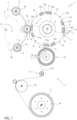
Figure 1 is a schematic top view, with parts removed for clarity, of a labelling machine according to the present invention; -
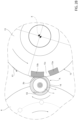
Figures 2A to 2C are larger-scale top views, with parts removed for clarity, of part of a transfer drum and a carousel of the labelling machine ofFigure 1 , during distinct and successive operative conditions; and -
Figures 3A and3B are larger-scale top views, with parts removed for clarity, of part of a transfer drum and a carousel of a labelling machine according to a further preferred embodiment of the present invention, during distinct and successive operative conditions. - With reference to
Figure 1 ,number 1 indicates as a whole a labelling machine configured for labellingcontainers 2, such as bottles, flacons or the like, adapted to contain a pourable product, preferably a pourable food product (such as water, soft drinks, beer, wine, juice, milk, or the like). - In particular,
machine 1 is configured for labellingcontainers 2 by means oflabels 3 obtained from aweb 4 of labelling material. - According to this preferred and non-limiting embodiment,
labels 3 are defined by glued labels, i.e. strips of labelling material that are cut at predetermined lengths fromweb 4 and then sprinkled with glue before their application on therespective containers 2. -
Web 4 is provided in the form of a continuous strip initially wound in areel 5 and is progressively unwound, in use, offreel 5, according to a known manner. - As visible in
figure 1 ,labelling machine 1 comprises: - a
carousel 6 rotatable about a central axis Z, preferably vertical, and configured to advance a plurality ofcontainers 2 along an arc-shaped labelling path L, preferably horizontal, around axis Z; and - a labelling module 7 (only schematically shown), arranged peripherally to
carousel 6 and configured for preparing a plurality oflabels 3 starting fromweb 4 and feedingsuch labels 3 tocarousel 6 at an application station A, so as to apply them ontorespective containers 2. -
Labelling module 7 is substantially of the known type and comprises: - a support member, preferably in the form of at least one
support shaft 8, for supporting onereel 5 at a time in an unwindable manner; - a
feed roller 10 mounted in a rotatable manner tomodule 7, actuatable in rotation forfeeding web 4 along a feed path P which extends within and throughlabelling module 7, and conveniently arranged downstream ofsupport shaft 8 along feed path P; - a plurality of guide rollers 11 (only one shown), arranged downstream of
support member 8, and configured to support theweb 4 progressively unwound fromreel 5 and to guideweb 4 along feed path P; - a cutting unit 12 (known per se and not described in detail) arranged downstream of
guide rollers 11, along feed path P, and configured to repeatedly cutweb 4 thereby obtaining a sequence oflabels 3 therefrom; and - a
transfer drum 13, preferably a vacuum drum of the known type, arranged downstream ofcutting unit 12, and mounted onmodule 7 in a rotatable manner about a central axis X which is preferably parallel to axis Z. - Preferably, drum 13 has a substantially cylindrical or toroidal-lobed configuration, with axis X defining a central rotation axis thereof.
-
Drum 13 has an outerlateral surface 13a and is configured to receive the previously cutlabels 3 from cuttingunit 12 at a receiving station R, to retainsuch labels 3, and to transferlabels 3 to application station A by means of a rotation about axis X, for the application thereof ontorespective containers 2. - It can be possible that the cutting unit acts on the web carried by the
drum 13. Therefore, in this case the cuttingunit 12 is configured for separating each label from the web while the label is carried by the drum 13.In this case, thedrum 13 receives thelabels 3 while thelabels 3 are still joined to each other to define the web. -
Labelling module 7 further comprises at least oneglue roller 14 arranged peripherally (and substantially tangent) to drum 13, at a gluing station G, and configured for spreading glue on at least the leading and trailing ends of eachindividual label 3, before the application thereof on therespective containers 2. - In detail,
glue roller 14 is configured to sequentially spread glue on aleading end 3a and on a trailingend 3b of eachlabel 3 carried bydrum 13. - In light of the above:
- cutting
unit 12 is arranged peripherally to drum 13; - gluing station G is operatively upstream of application station A and operatively downstream of receiving station R, with respect to the direction of rotation (counterclockwise in
figure 1 ) ofdrum 13 about axis X. - Advantageously,
carousel 6 comprises a plurality ofsupport plates 16 for supportingcontainers 2 during their advancement along labelling path L. - In detail, each
support plate 16 is configured for cyclically receiving and supporting onerespective container 2, and is rotatable for determining a rotation of the supportedcontainer 2 on its own longitudinal axis during its advancement along labelling path L. - In greater detail,
support plates 16 are rotatably mounted to a peripheral portion 6a ofcarousel 6. - The revolution of each
container 2 eases the wrapping of therespective label 3 around the outer lateral surface thereof. -
Drum 13 comprises at least one retainingsector 15 configured to cyclically receive and retain a label, by means of suction. - In detail, as visible in
Figure 1 , drum 13 comprises a plurality of retainingsectors 15 which are angularly distributed around axis X. - In the preferred embodiment shown,
drum 13 comprises four retainingsectors 15. - Each retaining
sector 15 is configured to cyclically receive onelabel 3 at a time at receiving station R, to retain saidlabel 3 by suction, and to release saidlabel 3, at application station A, to arespective container 2 to be labelled. - To this end, retaining
sectors 15 are provided with vacuum ports or slots or holes (not shown) as described in the introductory portion of the present description. -
Surface 13a is defined by the assembly of the outer lateral surfaces of all retainingsectors 15. - For the sake of brevity, reference will be made in the following to a
single retaining sector 15, to asingle label 3 retained thereon, and to asingle container 2 to be labelled supported by arespective support plate 16. However, all the features described and illustrated forsuch sector 15 are equally applicable to allsectors 15 ofdrum 13 and to all thecontainers 2 supported bycarousel 6. - As visible in particular in
Figures 2A-2C , retainingsector 15 includes: - a
leading pad 15a configured for retainingleading end 3a oflabel 3; - a trailing
pad 15b configured for retaining trailingend 3b oflabel 3; and - an
interpad region 15c interposed, and in particular angularly interposed, between leadingpad 15a and trailingpad 15b. - Preferably, retaining sector also comprises a pre-pad region located upstream of (i.e. angularly preceding) leading
pad 15a, and configured for providing an initial sliding ofweb 4 onsurface 13a at receiving station R, known per se and not described in detail. - In light of the above, retaining
sector 15 is, and in particularleading pad 15a and trailingpad 15b are, configured to release therespective label 3 to thecontainer 2 supported by therespective support plate 16 at application station A. - More precisely, leading
pad 15a is configured to applyleading end 3a to thecontainer 2 supported by therespective support plate 16 at application station A; similarly, the trailingpad 15b is configured to apply trailingend 3b to thesame container 2 at application station A. - According to an aspect of the invention, labelling
machine 1 is configured for labellingcontainers 2 by means ofpartial labels 3, each partial label being alabel 3 the longitudinal extension of which is smaller than the total angular extension of the outer lateral surface of therespective container 2, or alabel 3 which, once completely applied on therespective container 2 or at the end of the labelling process, covers an angular sector of the outer lateral surface of thecontainer 2 the angular extension of which is smaller than 360°, or smaller than 200°, or smaller than 180°. This is schematized in the appended figures. The invention is in particular configured for allowing a correct application of very short labels, for example wherein said angular sector is less than 200° or less than 180°. - In one embodiment, the angular extension of such angular sector is between 180° and 360°.
- In one embodiment, the angular extension of such angular sector is less than 30°.
- As said, the shorter the label, the more difficult and complicated is the transfer of such
partial label 3 fromdrum 13 tocarousel 6, i.e. from receivingsector 15 tocontainer 2. - The
labelling machine 1 is configured to control the angular speed of eachsupport plate 16, so that the peripheral speed of the supportedcontainer 2 is higher than a peripheral speed of thetransfer drum 13 in at least one instant during the release of therespective label 3 by therespective retaining sector 15. - In this way, the application of the label can be quicker, so that the label can be applied with a pad to pad technique also in case the label is very short.
- According to an important aspect of the invention, labelling
machine 1 is configured to control an increase of the angular speed of saidrespective support plate 16, with respect to the axis thereof, during the release oflabel 3 onto thecontainer 2 supported thereon (figures 2A-2B ). - In particular, labelling
machine 1 is configured to control the aforesaid increase of the angular speed of saidrespective support plate 16 such that a peripheral speed of the supportedcontainer 2 increases and is higher than a peripheral speed ofdrum 13 in at least one instant during the release oflabel 3 by retainingsector 15. - More in particular, labelling
machine 1 is configured to control the aforesaid increase between the application of leadingend 3a by leadingpad 15a and the application of trailingend 3b by trailingpad 15b onto thecontainer 2 supported by saidrespective support plate 16. - Even more in particular, labelling
machine 1 is configured to control the aforesaid increase after the application of leadingend 3a by leadingpad 15a and prior to the application of trailingend 3b by trailingpad 15b onto thecontainer 2 supported by saidrespective support plate 16. - This configuration is schematized in
Figure 2B . -
Drum 13 is configured to rotate about axis X with a peripheral speed having a first value V1. - According to the invention, labelling
machine 1 is configured to increase the aforesaid peripheral speed of the supportedcontainer 2, during the release oflabel 3 by retainingsector 15, up to a second value V2 which is higher than said first value V1 (Figure 2B ). - More specifically, labelling
machine 1 is configured so that the supportedcontainer 2 rotates with a peripheral speed having the first value V1 during the application of leadingend 3a by leadingpad 15a (Figure 2A ), and so that the supportedcontainer 2 rotates with a peripheral speed having the second value V2 during the application of trailingend 3b by trailingpad 15b (Figure 2B ). - In other words, said
respective support plate 16 is configured to rotate so that the supported container has a peripheral speed having the first value V1 during the application of leadingend 3a by leadingpad 15a, and has a peripheral speed having the second value V2 during the application of trailingend 3b by trailingpad 15b. - Hence, due to the above-described operative configuration of
labelling machine 1 according to the invention, saidrespective support plate 16 is configured to determine, by means of said increase in its peripheral speed, a sliding of trailingend 3b onto trailingpad 15b (schematized inFigure 2B ). - Thanks to this advantageous and peculiar configuration,
label 3 is withdrawn fromdrum 13, by means of the sudden acceleration ofsupport plate 16, in a shorter time, with respect to a completely homokinetic label application as described in the introductory portion of the present description. - This is particularly advantageous when and for
labelling containers 2 withpartial labels 3, either with the aforementioned pad-to-pad technique or with the aforementioned flag labelling technique. - In fact, as for the pad-to-pad technique, the transferring (i.e. the application) of
partial label 3 is faster, namely is completed while the relative support plate 16 (and therefore the relative container 2) has traveled a shorter angular distance with respect to the carousel axis Z. Therefore,container 2 is closer to drum 13 and to application station A when trailingend 3b is to be applied thereon, also becausedrum 13 has traveled a shorter angular distance with respect to its axis X. In this way, the labelling by means of partial labels and through the pad to pad technique can occur correctly also in case of partial very short labels. - Hence, for these reasons the Applicant has observed that the transfer of
partial labels 3 is largely improved, with respect to a completely homokinetic label application (i.e. an application during which supportplate 16 is always homokinetic with drum 13). The labelling machine according to the invention is configured for applying label with overspeed of the containers with respect to the drum, and in this way obtains an accurate application of the labels also in case of very short labels. - As for the flag labelling technique, the aforementioned flapping or waving of the trailing
end 3b of apartial label 3 is highly reduced, since the transfer oflabel 3 is faster. - Conveniently, once
label 3 is completely released from retainingsector 15, i.e. once trailingend 3b is completely applied oncontainer 2, therespective support plate 16 is configured to decelerate so that the supportedcontainer 2 has again a peripheral speed having the first value V1 (Figure 2c ). - More specifically, the
respective support plate 16 is configured to decelerate so that the supported container has a peripheral speed having the first value V1 when passing again at application station A for receiving theleading end 3a of asubsequent label 3. - In other words, labelling
machine 1 is configured so that the peripheral speed of each supportedcontainer 2 is decreased up to the first value V1 after application of trailingend 3b thereon and until theleading end 3a of asubsequent label 3 is applied thereon. - As visible in the appended Figures, each
leading pad 15a and each trailingpad 15b extends angularly onto outerlateral surface 13a ofdrum 13, with respect to axis X. - Advantageously, the angular extension of the trailing
pad 15a is greater than the angular extension of leadingpad 15b. - In this way, trailing
end 3b is well supported during its sliding on trailingpad 15b during the increase of angular/peripheral speed of therespective support plate 16. - Conveniently, labelling
machine 1 comprises a plurality of actuators, such as servomotors or electric motors or pneumatic actuators or fluid-dynamic actuators (not shown), each coupled to onerespective support plate 16 for driving the rotation thereof. - Therefore, the
support plates 16 are thereby configured to be accelerated and decelerated in their rotation about their own axes independently from one another. - Thanks to this configuration, flexibility of control of
support plates 16 is largely improved. - Alternatively, labelling
machine 1 comprises a single actuator, for example of the type described above (not shown), coupled to all thesupport plates 16 via a single transmission system (not shown). - Hence, the
support plates 16 are thereby configured to be accelerated and decelerated in their rotation about their own axes jointly with one another. - This alternative configuration allows for a simpler architecture of
machine 1. -
Figures 3A and3B show an alternative preferred embodiment oflabelling machine 1 according to the present invention. - Being such alternative embodiment similar to the embodiment described above, only the difference between them will be highlighted hereinafter, using the same reference numbers for corresponding or equal parts.
- According to this alternative embodiment, each
support plate 16 is homokinetic withdrum 13 during the release of therespective label 3, i.e. during complete application ofsuch label 3 onto therespective container 2 supported thereon. - Advantageously, trailing
pad 15b is configured to switch from a suction configuration, in which it retains trailingend 3b by suction (Figure 3A ), to a blowing configuration, in which it emits a jet of air (Figure 3B ), between the application of leadingend 3a by leadingpad 15a and the application of trailingend 3b by trailingpad 15b on therespective container 2. - In other words, labelling
machine 1 is configured so that trailingpad 15b switches from the suction configuration to the blowing configuration between the application of leadingend 3a by leadingpad 15a and the application of trailingend 3b by trailingpad 15b. - More specifically, trailing
pad 15b is configured for blowing trailingend 3b, with said jet of air, off outerlateral surface 13a ofdrum 13 and towards therespective container 2 at application station A. - Thanks to this configuration, the transfer of each
label 3 from therespective receiving sector 15 to therespective container 2 is highly improved. - In detail, this configuration is particularly advantageous in case the flag labelling technique is used: the blowing effect on trailing
end 3b can replace the function of the aforementioned wiping device. The architecture oflabelling machine 1 is therefore improved. - From the foregoing, it is clear how
labelling machine 1 allows for implementing a method for labelling containers adapted to contain a pourable product with partial labels, the method comprising the steps of: - a) advancing a plurality of containers to be labelled along a labelling path and through an application station;
- b) feeding a web of labelling material along a feed path;
- c) repeatedly cutting the web thereby separating a sequence of labels therefrom;
- d) receiving such labels onto a transfer drum rotatable about a rotation axis and comprising a plurality of retaining sectors each configured to cyclically receive and retain a label and each including a leading pad for retaining a leading end of the label and a trailing pad for retaining a trailing end of the label;
- e) cyclically conveying the leading pad and the trailing pad at the application station for the application of the labels on the respective containers;
- f) releasing the leading end at the application station, so as to apply the leading end on the respective container by means of the leading pad;
- g) releasing the trailing end at the application station, so as to apply the trailing end on the respective container by means of the trailing pad;
- h) rotating each container about its own longitudinal axis at least at the application station;
wherein the method comprises the step of:- i) controlling the angular speed of each container (2) transiting at the application station (A) in at least one instant between the step f) of releasing the leading end (3a) and the step g) of releasing the trailing end (3b), so that the peripheral speed of the supported container (2), in at least one instant during the application of the respective label, is higher than the peripheral speed of the transfer drum.
- In particular, the step i) of increasing comprises increasing a peripheral speed of each container transiting at the application station so that the peripheral speed of such container is higher than the peripheral speed of the transfer drum in at least one instant between the step f) of releasing the leading end and the step g) of releasing the trailing end.
- The advantages of
labelling machine 1 according to the present invention will be clear from the foregoing description. - In particular, thanks to a peripheral speed of the container which is higher than the peripheral speed of the drum in at least one instant during the release of the label, the transfer of
partial labels 3 is largely improved, with respect to a completely homokinetic label application (i.e. an application during which supportplate 16 is always homokinetic with drum 13). - This in fact allows a faster withdraw of the
partial label 3 from thedrum 13, which thereby results in a transfer ofsuch label 3 completed while the relative support plate 16 (and therefore the relative container 2) has traveled a shorter angular distance with respect to the carousel axis Z, and whiledrum 13 has traveled a shorter angular distance with respect to its axis X. - Therefore,
container 2 is closer to therelative retaining sector 15 and application station A when trailingend 3b is released and applied thereon. - Furthermore, if the second preferred embodiment is used, labelling
machine 1 according to the invention is particularly advantageous for the flag labelling technique: the blowing effect on trailingend 3b can replace the function of the aforementioned wiping device. The architecture oflabelling machine 1 is therefore improved. - Clearly, changes may be made to labelling
machine 1 as described herein without, however, departing from the scope of protection as defined in the accompanying claims.
Claims (16)
- - Labelling machine (1) for labelling containers (2) adapted to contain a pourable product, the labelling machine (1) comprising:- a carousel (6) for advancing a plurality of containers (2) to be labelled along a labelling path (L) ;- a feed roller (10) for feeding a web (4) of labelling material along a feed path (P);- a cutting unit (12) arranged along the feed path (P) and configured for repeatedly cutting the web (4) thereby separating a sequence of labels (2) therefrom;- a transfer drum (13) rotatable about a rotation axis (X) and configured to sequentially receive the labels (3) and to transfer such labels (3) to an application station (A) for the application thereof onto respective containers (2);the transfer drum (13) comprising at least one retaining sector (15) configured to cyclically receive and retain a label (3), the retaining sector (15) including a leading pad (15a) configured for retaining a leading end (3a) of the label (3) and a trailing pad (15b) configured for retaining a trailing end (3b) of the label (3);wherein the labelling machine (1) is configured for labelling the containers (2) by means of partial labels (3), each partial label (3) being a label the longitudinal extension of which is smaller than the total angular extension of the outer lateral surface of the respective container (2), or a label which, once completely applied on the respective container (2) or at the end of the labelling process, covers an angular sector of the outer lateral surface of the container (2) the angular extension of which is smaller than 200°, and preferably smaller than 180°.
- - Labelling machine as claimed in claim 1, wherein the carousel (6) comprises a plurality of support plates (16), each configured for cyclically receiving and supporting one respective container (2), and each rotatable on its own axis for determining a rotation of the supported container (2);wherein said retaining sector (15) is configured to release the respective label (3) to the container (2) supported by a respective support plate (16) at the application station (A);and wherein the labelling machine (1) is configured to control the angular speed of each support plate (16), so that the peripheral speed of the supported container (2) is higher than a peripheral speed of the transfer drum (13) in at least one instant during the release of the respective label (3) by the respective retaining sector (15).
- - Labelling machine as claimed in claim 2, wherein the labelling machine (1) is configured to control an increase of said angular speed such that a peripheral speed of the supported container (2) increases to be higher than a peripheral speed of the transfer drum (13) in at least one instant during the release of the label (3) by the retaining sector (15).
- - Labelling machine as claimed in claim 3, wherein, for each retaining sector (15), the leading pad (15a) is configured to apply said leading end (3a) to the container (2) supported by the respective support plate (16) at the application station (A) and the trailing pad (15b) is configured to apply said trailing end (3b) to the same container at the application station (A);
and wherein the labelling machine (1) is configured to control said increase of the angular speed (16) between the application of the leading end (3a) by the leading pad (15a) of the respective sector (15) onto the container (2) supported by the respective support plate (16), and the application of the trailing end (3b) by the trailing pad (15b) of the respective sector (15) onto the container (2) supported by said respective support plate (16). - - Labelling machine as claimed in claim 4, wherein the labelling machine (1) is configured to control said increase after the application of the leading end (3a) by the leading pad (15a) of the respective sector (15) onto the container (2) supported by said respective support plate (16), and prior to the application of the trailing end (3b) by the trailing pad (15b) onto the container (2) supported by said respective support plate (16).
- - Labelling machine as claimed in any of the claims 2 to 5, wherein the transfer drum (13) is configured to rotate about said rotation axis (X) with a peripheral speed having a first value (V1);
and wherein the labelling machine (1) is configured so that the peripheral speed of each supported container (2), in at least one instant during the release of the respective label (3) by the respective retaining sector (15), has a second value (V2) which is higher than said first value (V1). - - Labelling machine as claimed in claim 6, wherein the labelling machine (1) is configured so that each supported container (2) rotates with a peripheral speed having said first value (V1) during the application of the leading end (3a) by the leading pad (15a) of the respective sector (15), and so that each supported container (2) rotates with a peripheral speed having said second value (V2) during the application of the trailing end (3b) by the trailing pad (15b) of the respective sector (15).
- - Labelling machine as claimed in any of the claims 2 to 7, wherein each support plate (16) is configured to determine, by means of said control of the angular speed, a sliding of the trailing end (3b) of the respective label onto the trailing pad (15b) of the respective sector (15).
- - Labelling machine as claimed in any one of the claims 2 to 8, wherein each leading pad (15a) and each trailing pad (15b) extends angularly onto an outer lateral surface (13a) of the transfer drum (13), with respect to said rotation axis (X);
and wherein, for each retaining sector (15), the trailing pad (15b) has an angular extension greater than the angular extension of the leading pad (15a). - - Labelling machine as claimed in any of claims 2 to 9, comprising a plurality of actuators, each coupled to one respective support plate (16) for driving the rotation thereof, the support plates (16) being thereby configured to be accelerated and decelerated in their rotation about their own axes independently from one another.
- - Labelling machine as claimed in any of claims 2 to 9, and comprising a single actuator coupled to each support plate (16) via a single transmission system, the support plates (16) being thereby configured to be accelerated and decelerated in their rotation about their own axes jointly with one another.
- - Labelling machine as claimed in claim 1, wherein the leading pad (15a) and the trailing pad (15b) are configured to cyclically retain a respective label (3) by means of suction,wherein, for each retaining sector (15), the leading pad (15a) is configured to apply said leading end (3a) to the respective container (2) at the application station (A) and the trailing pad (15b) is configured to apply said trailing end (3b) to the same container (2) at the application station (A),and wherein the trailing pad (15b) is configured to switch from a suction configuration, in which it retains the trailing end (3b) by suction, to a blowing configuration, in which it emits a jet of air, between the application of the leading end (3a) by the leading pad (15a) and the application of the trailing end (3b) by the trailing pad (15b).
- - Labelling machine as claimed in claim 12, wherein the trailing pad (15b) is configured for blowing the trailing end (3b), with said jet of air, off the outer lateral surface (13a) of the transfer drum (13) and towards the respective container (2) at the application station (A).
- Machine according to any of the previous Claims, wherein the cutting unit (12) is configured for separating each label from the web while the label is carried by the drum.
- - Method for labelling containers (2) adapted to contain a pourable product with partial labels (3), each partial label (3) being a label the longitudinal extension of which is smaller than the total angular extension of the outer lateral surface of each respective container (2), or a label which, once completely applied on the respective container (2) or at the end of the labelling process, covers an angular sector of the outer lateral surface of the container (2) the angular extension of which is smaller than 360°, the method comprising the steps of:a) advancing a plurality of containers (2) to be labelled along a labelling path (L) and through an application station (A);b) feeding a web (4) of labelling material along a feed path (P);c) repeatedly cutting the web (4) thereby separating a sequence of labels (3) therefrom;d) receiving such labels (3) onto a transfer drum (13) rotatable about a rotation axis (X) and comprising a plurality of retaining sectors (15) each configured to cyclically receive and retain a label (3) and each including a leading pad (15a) for retaining a leading end (3a) of the label (3) and a trailing pad (15b) for retaining a trailing end (3b) of the label (3);e) cyclically conveying the leading pad (15a) and the trailing pad (15b) at the application station (A) for the application of the labels (3) on the respective containers (2);f) releasing the leading end (3a) at the application station (A), so as to apply the leading end (3a) on the respective container (2) by means of the leading pad (15a);g) releasing the trailing end (3b) at the application station (A), so as to apply the trailing end (3b) on the respective container (2) by means of the trailing pad (15b);h) rotating each container (2) about its own longitudinal axis at least at the application station (A) ;
wherein the method comprises the step of:i) controlling the angular speed of each container (2) transiting at the application station (A) in at least one instant between the step f) of releasing the leading end (3a) and the step g) of releasing the trailing end (3b), so that the peripheral speed of the supported container (2), in at least one instant during the application of the respective label, is higher than the peripheral speed of the transfer drum. - - Method as claimed in claim 15, wherein the step i) of controlling comprises increasing a peripheral speed of each container (2) transiting at the application station (A) so that the peripheral speed of such container (2) is higher than the peripheral speed of the transfer drum (13) in at least one instant between the step f) of releasing the leading end (3a) and the step g) of releasing the trailing end (3b).
Priority Applications (2)
| Application Number | Priority Date | Filing Date | Title |
|---|---|---|---|
| EP23191679.2A EP4509415A1 (en) | 2023-08-16 | 2023-08-16 | Labelling machine configured for labelling containers by means of partial labels by sliding application |
| PCT/EP2024/072375 WO2025036797A1 (en) | 2023-08-16 | 2024-08-07 | Labelling machine configured for labelling containers by means of partial labels by sliding application |
Applications Claiming Priority (1)
| Application Number | Priority Date | Filing Date | Title |
|---|---|---|---|
| EP23191679.2A EP4509415A1 (en) | 2023-08-16 | 2023-08-16 | Labelling machine configured for labelling containers by means of partial labels by sliding application |
Publications (1)
| Publication Number | Publication Date |
|---|---|
| EP4509415A1 true EP4509415A1 (en) | 2025-02-19 |
Family
ID=87580375
Family Applications (1)
| Application Number | Title | Priority Date | Filing Date |
|---|---|---|---|
| EP23191679.2A Pending EP4509415A1 (en) | 2023-08-16 | 2023-08-16 | Labelling machine configured for labelling containers by means of partial labels by sliding application |
Country Status (2)
| Country | Link |
|---|---|
| EP (1) | EP4509415A1 (en) |
| WO (1) | WO2025036797A1 (en) |
Citations (8)
| Publication number | Priority date | Publication date | Assignee | Title |
|---|---|---|---|---|
| US5116452A (en) * | 1990-12-06 | 1992-05-26 | Krones Ag Hermann Kronseder Maschinenfabrik | Device for applying labels to containers |
| US5380381A (en) * | 1993-06-03 | 1995-01-10 | B & H Manufacturing Company, Inc. | Labeling machine with variable speed cutting head |
| US20090236023A1 (en) * | 2008-03-19 | 2009-09-24 | Nordson Corporation | Apparatus And Methods For Dispensing Adhesive To Labels |
| WO2010013399A1 (en) * | 2008-08-01 | 2010-02-04 | 株式会社フジシールインターナショナル | Label attaching apparatus |
| WO2010016187A1 (en) * | 2008-08-08 | 2010-02-11 | 株式会社フジシールインターナショナル | Labeling device |
| US20110048629A1 (en) * | 2008-02-26 | 2011-03-03 | James Frederick Robertson Carmichael | Vacuum drum for labelling machines |
| DE202016105825U1 (en) * | 2016-10-18 | 2018-01-22 | Krones Ag | Labeling unit for applying form labels to containers |
| EP3992095A1 (en) * | 2020-10-30 | 2022-05-04 | Sidel Participations | Labelling machine and method for applying labels onto articles adapted to contain a pourable product |
-
2023
- 2023-08-16 EP EP23191679.2A patent/EP4509415A1/en active Pending
-
2024
- 2024-08-07 WO PCT/EP2024/072375 patent/WO2025036797A1/en not_active Ceased
Patent Citations (8)
| Publication number | Priority date | Publication date | Assignee | Title |
|---|---|---|---|---|
| US5116452A (en) * | 1990-12-06 | 1992-05-26 | Krones Ag Hermann Kronseder Maschinenfabrik | Device for applying labels to containers |
| US5380381A (en) * | 1993-06-03 | 1995-01-10 | B & H Manufacturing Company, Inc. | Labeling machine with variable speed cutting head |
| US20110048629A1 (en) * | 2008-02-26 | 2011-03-03 | James Frederick Robertson Carmichael | Vacuum drum for labelling machines |
| US20090236023A1 (en) * | 2008-03-19 | 2009-09-24 | Nordson Corporation | Apparatus And Methods For Dispensing Adhesive To Labels |
| WO2010013399A1 (en) * | 2008-08-01 | 2010-02-04 | 株式会社フジシールインターナショナル | Label attaching apparatus |
| WO2010016187A1 (en) * | 2008-08-08 | 2010-02-11 | 株式会社フジシールインターナショナル | Labeling device |
| DE202016105825U1 (en) * | 2016-10-18 | 2018-01-22 | Krones Ag | Labeling unit for applying form labels to containers |
| EP3992095A1 (en) * | 2020-10-30 | 2022-05-04 | Sidel Participations | Labelling machine and method for applying labels onto articles adapted to contain a pourable product |
Also Published As
| Publication number | Publication date |
|---|---|
| WO2025036797A1 (en) | 2025-02-20 |
Similar Documents
| Publication | Publication Date | Title |
|---|---|---|
| US11186401B2 (en) | Labelling machine configured to apply labels onto articles for containing a pourable product | |
| US11993415B2 (en) | Machine and method for labeling containers | |
| EP0944528B1 (en) | Roll-fed labelling apparatus | |
| US3765991A (en) | Labeling apparatus | |
| US5082520A (en) | Automatic high-speed labeling machine employing various linear and rotational speeds of the container | |
| US4714515A (en) | Straight line container labeling apparatus | |
| US10661936B2 (en) | Labelling group and method for applying a plurality of labels onto respective articles | |
| US5116452A (en) | Device for applying labels to containers | |
| EP4594194B1 (en) | Labelling module configured for labelling with partial labels | |
| WO2019121152A1 (en) | Labelling machine and labelling method for the application of label sheets on receptacles | |
| CA2039294C (en) | High speed labeling machine | |
| CN110217456A (en) | Labelling machine and for by label paper patch method to the container | |
| EP4219102B1 (en) | Labelling module for applying labels obtained from a web of labelling material onto articles adapted to contain a pourable product | |
| US11981043B2 (en) | Cutting device for cutting labels from a web of labelling material | |
| WO2025036797A1 (en) | Labelling machine configured for labelling containers by means of partial labels by sliding application | |
| EP4520674A1 (en) | Label transfer drum with single-piece pad devices for labelling containers by means of partial labels | |
| EP3988462A1 (en) | Labelling machine and method for applying labels onto articles adapted to contain a pourable product | |
| EP4440939B1 (en) | Labelling module for applying labels onto articles adapted to contain a pourable product | |
| WO2023083638A1 (en) | Labelling module for applying labels onto containers adapted to contain a pourable product | |
| US4377432A (en) | Method and apparatus for affixing labels and foils to bottles | |
| EP4601954A1 (en) | Labeling module with optimized start-up | |
| WO2024146698A1 (en) | Labelling machine with automatic quality improvement capability based on visual detection |
Legal Events
| Date | Code | Title | Description |
|---|---|---|---|
| PUAI | Public reference made under article 153(3) epc to a published international application that has entered the european phase |
Free format text: ORIGINAL CODE: 0009012 |
|
| STAA | Information on the status of an ep patent application or granted ep patent |
Free format text: STATUS: THE APPLICATION HAS BEEN PUBLISHED |
|
| AK | Designated contracting states |
Kind code of ref document: A1 Designated state(s): AL AT BE BG CH CY CZ DE DK EE ES FI FR GB GR HR HU IE IS IT LI LT LU LV MC ME MK MT NL NO PL PT RO RS SE SI SK SM TR |
|
| STAA | Information on the status of an ep patent application or granted ep patent |
Free format text: STATUS: REQUEST FOR EXAMINATION WAS MADE |
|
| 17P | Request for examination filed |
Effective date: 20250812 |