EP4509403A1 - Flying device - Google Patents
Flying device Download PDFInfo
- Publication number
- EP4509403A1 EP4509403A1 EP23788220.4A EP23788220A EP4509403A1 EP 4509403 A1 EP4509403 A1 EP 4509403A1 EP 23788220 A EP23788220 A EP 23788220A EP 4509403 A1 EP4509403 A1 EP 4509403A1
- Authority
- EP
- European Patent Office
- Prior art keywords
- engine
- transmission shaft
- engine unit
- rotor
- crankshaft
- Prior art date
- Legal status (The legal status is an assumption and is not a legal conclusion. Google has not performed a legal analysis and makes no representation as to the accuracy of the status listed.)
- Pending
Links
Images



Classifications
-
- B—PERFORMING OPERATIONS; TRANSPORTING
- B64—AIRCRAFT; AVIATION; COSMONAUTICS
- B64C—AEROPLANES; HELICOPTERS
- B64C11/00—Propellers, e.g. of ducted type; Features common to propellers and rotors for rotorcraft
- B64C11/46—Arrangements of, or constructional features peculiar to, multiple propellers
- B64C11/48—Units of two or more coaxial propellers
-
- B—PERFORMING OPERATIONS; TRANSPORTING
- B64—AIRCRAFT; AVIATION; COSMONAUTICS
- B64C—AEROPLANES; HELICOPTERS
- B64C27/00—Rotorcraft; Rotors peculiar thereto
- B64C27/04—Helicopters
- B64C27/08—Helicopters with two or more rotors
- B64C27/10—Helicopters with two or more rotors arranged coaxially
-
- B—PERFORMING OPERATIONS; TRANSPORTING
- B64—AIRCRAFT; AVIATION; COSMONAUTICS
- B64D—EQUIPMENT FOR FITTING IN OR TO AIRCRAFT; FLIGHT SUITS; PARACHUTES; ARRANGEMENT OR MOUNTING OF POWER PLANTS OR PROPULSION TRANSMISSIONS IN AIRCRAFT
- B64D35/00—Transmitting power from power plants to propellers or rotors; Arrangements of transmissions
- B64D35/02—Transmitting power from power plants to propellers or rotors; Arrangements of transmissions specially adapted for specific power plants
- B64D35/021—Transmitting power from power plants to propellers or rotors; Arrangements of transmissions specially adapted for specific power plants for electric power plants
- B64D35/022—Transmitting power from power plants to propellers or rotors; Arrangements of transmissions specially adapted for specific power plants for electric power plants of hybrid-electric type
- B64D35/024—Transmitting power from power plants to propellers or rotors; Arrangements of transmissions specially adapted for specific power plants for electric power plants of hybrid-electric type of series type
-
- B—PERFORMING OPERATIONS; TRANSPORTING
- B64—AIRCRAFT; AVIATION; COSMONAUTICS
- B64U—UNMANNED AERIAL VEHICLES [UAV]; EQUIPMENT THEREFOR
- B64U30/00—Means for producing lift; Empennages; Arrangements thereof
- B64U30/20—Rotors; Rotor supports
- B64U30/24—Coaxial rotors
-
- B—PERFORMING OPERATIONS; TRANSPORTING
- B64—AIRCRAFT; AVIATION; COSMONAUTICS
- B64U—UNMANNED AERIAL VEHICLES [UAV]; EQUIPMENT THEREFOR
- B64U50/00—Propulsion; Power supply
- B64U50/10—Propulsion
- B64U50/11—Propulsion using internal combustion piston engines
-
- B—PERFORMING OPERATIONS; TRANSPORTING
- B64—AIRCRAFT; AVIATION; COSMONAUTICS
- B64U—UNMANNED AERIAL VEHICLES [UAV]; EQUIPMENT THEREFOR
- B64U50/00—Propulsion; Power supply
- B64U50/10—Propulsion
- B64U50/19—Propulsion using electrically powered motors
-
- B—PERFORMING OPERATIONS; TRANSPORTING
- B64—AIRCRAFT; AVIATION; COSMONAUTICS
- B64U—UNMANNED AERIAL VEHICLES [UAV]; EQUIPMENT THEREFOR
- B64U50/00—Propulsion; Power supply
- B64U50/20—Transmission of mechanical power to rotors or propellers
- B64U50/23—Transmission of mechanical power to rotors or propellers with each propulsion means having an individual motor
-
- B—PERFORMING OPERATIONS; TRANSPORTING
- B64—AIRCRAFT; AVIATION; COSMONAUTICS
- B64U—UNMANNED AERIAL VEHICLES [UAV]; EQUIPMENT THEREFOR
- B64U50/00—Propulsion; Power supply
- B64U50/30—Supply or distribution of electrical power
- B64U50/33—Supply or distribution of electrical power generated by combustion engines
Definitions
- the present invention relates to a flight device and specifically relates to a flight device in which the rotor is driven by an engine.
- Flight devices capable of unmanned flight in the air have been known. Such a flight device is able to fly in the air using the thrust of a rotor rotating about a vertical axis.
- Flight devices include the field of transportation, the field of surveying, and the field of photography, for example.
- surveying equipment and photography equipment are attached to the flight devices.
- the flight devices can fly in areas that human cannot access and perform transportation, photographing, and surveying of such areas.
- Inventions relating to such flight devices are described in Patent Literature 1 and Patent Literature 2, for example.
- a typical flight device the aforementioned rotor rotates using electric power supplied from a storage battery mounted on the flight device.
- energy supply by the electric power of the storage battery may not always be sufficient.
- flight devices equipped with engines also have emerged.
- a generator is rotated using driving force of the engine, and the rotor is rotationally driven using electric power generated by the generator.
- the engine and the generator are connected in series on a path of energy supplied from the power source to the rotor.
- Such a flight device is therefore called a series-type drone. Use of such flight devices enables photography and surveying of wide areas.
- Patent Literature 3 A flight device equipped with an engine is described in Patent Literature 3, for example. Furthermore, parallel-type hybrid drones are also gradually emerging, in which the main rotor is mechanically rotated using the driving force of the engine and a sub-rotor is rotated using a motor.
- many drones as existing flight devices, include plural motors or engines, and because of remaining vibrations or anti-torque due to engines, it is difficult to accurately control the position and orientation of drones in the air. Furthermore, remaining vibrations or anti-torque due to generators also causes a similar problem.
- a gear box or the like may be provided in the drive transmission system.
- a gear box or the like will increase the complexity of the overall structure of the drone and increase its weight, thus reducing the continuous flight time of the drone.
- the present invention was made in the light of the aforementioned circumstances, and an object thereof is to provide a flight device in which vibrations and anti-torque generated during flight are effectively reduced.
- a flight device of the present invention includes an engine, a transmission shaft, and a rotor
- the engine includes a first engine unit and a second engine unit
- the transmission shaft includes a first transmission shaft rotated by the first engine unit and a second transmission shaft rotated by the second engine unit
- the rotor includes a first rotor rotated by the first transmission shaft and a second rotor rotated by the second transmission shaft
- the first transmission shaft has a hollow structure
- the second transmission shaft is arranged inside the first transmission shaft.
- the first engine unit and the second engine unit are arranged to face each other.
- the first engine unit includes a first piston, a first crankshaft, and a first connecting rod rotatably connecting the first piston and the first crankshaft
- the second engine unit includes a second piston, a second crankshaft, and a second connecting rod rotatably connecting the second piston and the second crankshaft
- the first transmission shaft and the first crankshaft are drivingly connected with a first drive transmission unit interposed therebetween
- the second transmission shaft and the second crankshaft are drivingly connected with a second drive transmission unit interposed therebetween.
- the engine further includes a third engine unit and a fourth engine unit, the first rotor is rotated by the first engine unit and the third engine unit, and the second rotor is rotated by the second engine unit and the fourth engine unit.
- the first crankshaft and the second crankshaft rotate in opposite directions.
- the flight device of the present invention further includes a first generator and a second generator, the first generator is driven by the first engine unit, and the second generator is driven by the second engine unit.
- the flight device of the present invention further includes a sub-rotor, wherein the sub-rotor is rotationally driven by a motor.
- a flight device of the present invention includes an engine, a transmission shaft, and a rotor, in which the engine includes a first engine unit and a second engine unit, the transmission shaft includes a first transmission shaft rotated by the first engine unit and a second transmission shaft rotated by the second engine unit, the rotor includes a first rotor rotated by the first transmission shaft and a second rotor rotated by the second transmission shaft, the first transmission shaft has a hollow structure, and the second transmission shaft is arranged inside the first transmission shaft.
- the engine includes the first engine unit and the second engine unit, so that vibrations and torque generated by the engine units cancel each other out. This reduces vibrations and the like generated by the engine during flight, thus stabilizing the position and orientation during flight.
- the first engine unit and the second engine unit are arranged to face each other.
- the first engine unit and the second engine unit are arranged to face each other, so that the effect of cancelling vibrations, torque, or the like each other out can be further enhanced.
- the first engine unit includes a first piston, a first crankshaft, and a first connecting rod rotatably connecting the first piston and the first crankshaft
- the second engine unit includes a second piston, a second crankshaft, and a second connecting rod rotatably connecting the second piston and the second crankshaft
- the first transmission shaft and the first crankshaft are drivingly connected with a first drive transmission unit interposed therebetween
- the second transmission shaft and the second crankshaft are drivingly connected with a second drive transmission unit interposed therebetween.
- the members of the first engine unit and the members of the second engine unit are arranged so as to face each other. This can extremely minimize vibrations and the like generated by running of the first engine unit and the second engine unit.
- the engine further includes a third engine unit and a fourth engine unit, the first rotor is rotated by the first engine unit and the third engine unit, and the second rotor is rotated by the second engine unit and the fourth engine unit.
- use of the third engine unit and the fourth engine unit as a power source in addition to the third engine unit and the fourth engine unit can improve the output of the rotor.
- the first crankshaft and the second crankshaft rotate in opposite directions.
- the rotation direction of the first crankshaft is opposite to that of the second crankshaft, so that the moments generated by rotation of the rotor cancel each other out. This can further improve the stability during flight.
- the flight device of the present invention further includes a first generator and a second generator, in which the first generator is driven by the first engine unit and the second generator is driven by the second engine unit. According to the flight device of the present invention, driving the first generator and the second generator can produce electric energy necessary for flight.
- the flight device of the present invention further includes a sub-rotor, in which the sub-rotor is rotationally driven by a motor. According to the flight device of the present invention, it is therefore possible to more effectively control the position and orientation during flight due to the sub-rotor.
- a flight device 10 is also called a drone and specifically also called a parallel-type hybrid drone.
- the parallel-type hybrid drone is a drone including a rotor mechanically driven by an engine and a rotor driven by a motor.
- Fig. 1 is a plan view of the flight device 10 as seen from above.
- the flight device 10 mainly includes an engine 11, a transmission shaft 12, and rotors 14.
- the flight device 10 is a parallel-type hybrid drone including two driving systems in parallel, an electric driving system and a mechanical driving system.
- the electric driving system is a driving system that rotates motors 21 and sub-rotors 15, which will be described later.
- the mechanical driving system is a driving system that rotates the rotors 14, which will be described later.
- the airframe 19 is a body supporting the units constituting the fright device 10 and is made of synthetic resin, metal, or a composite material thereof.
- the rotors 14 rotate to generate driving force necessary for the airframe 19 to float.
- the rotors 14 include a first rotor 141 and a second rotor 142.
- the first rotor 141 and the second rotor 142 constitute a contra-rotating propeller.
- the first rotor 141 and the second rotor 142 rotate in opposite directions at the same rotational speed. For example, in top view, the first rotor 141 rotates counterclockwise while the second rotor 142 rotates clockwise.
- the rotors 14 are main rotors mechanically rotated by driving force of the engine 11.
- the flight device 10 includes the sub-rotors 15.
- the sub-rotors 15 include sub-rotors 151 to 154.
- the sub-rotors 15 rotate to control the position and orientation of the flight device 10 during flight.
- the sub-rotor 151 is positioned at the front left of the airframe 19 and is rotated by a motor 211, which will be described later.
- the sub-rotor 152 is positioned at the back left of the airframe 19 and is rotated by a motor 212, which will be described later.
- the sub-rotor 153 is positioned at the front right of the airframe 19 and is rotated by a motor 213, which will be described later.
- the sub-rotor 154 is positioned at the back right of the airframe 19 and is rotated by a motor 214, which will be described later.
- Fig. 2 is a cross-sectional view of the flight device 10.
- the engine 11 is accommodated within the airframe 19, and the rotors 14 are provided above the airframe 19.
- the engine 11 includes a first engine unit 111 and a second engine unit 112.
- the first engine unit 111 includes a first piston 1111, a first crankshaft 1112, and a first connecting rod 1113, which rotatably connects the first piston 1111 and the first crankshaft 1112.
- the first crankshaft 1112 of the first engine unit 111 protrudes upward from the upper surface of the airframe 19.
- the second engine unit 112 includes a second piston 1121, a second crankshaft 1122, and a second connecting rod 1123, which rotatably connects the second piston 1121 and the second crankshaft 1122.
- the second crankshaft 1122 of the second engine unit 112 protrudes upward from the upper surface of the airframe 19.
- the first piston 1111 of the first engine unit 111 and the second piston 1121 of the second engine unit 41 share a combustion chamber 13.
- the first piston 1111 and the second piston 1121 reciprocate within a single continuing cylinder 25.
- the first piston 1111 and the second piston 1121 simultaneously making stroke toward the center, it is possible to achieve a high expansion ratio of gas mixture in the combustion chamber 13 while reducing the stroke amount.
- the engine 11 includes a volume space (not illustrated herein) communicating with the combustion chamber 13.
- a spark plug is arranged in the volume space.
- an intake port and an exhaust port which are not illustrated herein, are formed in the combustion chamber 13.
- An air-mixture containing fuel, such as gasoline, is introduced into the combustion chamber 13 through the intake port, and exhaust gas after combustion is discharged from the combustion chamber 13 to the outside through the exhaust port.
- the engine 11 configured as described above operates as follows. First, in an intake stroke, the first piston 1111 and the second piston 1121 move outward from the center within the cylinder 25 to introduce air mixture, as a mixture of air and fuel, into the cylinder 25. Next, in a compression stroke, the first piston 1111 and the second piston 1121 are forced toward the center due to inertia of the first and second crankshafts 1112 and 1122 that are rotating, and the air mixture is compressed within the cylinder 25. Then, in a combustion stroke, the not-illustrated spark plug ignites in the combustion chamber 13, and the air mixture burns within the cylinder 25. The first piston 1111 and the second piston 1121 are thereby forced to the respective outer ends, which are bottom dead centers.
- the two first and second pistons 1111 and 1121 which reciprocate within the single cylinder 25, can share strokes. Compared to typical gasoline engines, therefore, the compression ratio of gas mixture can be increased. Since the first piston 1111 and the second piston 1121 face each other within the cylinder 25, the engine 11 does not need a cylinder head that is necessary for general engines.
- the engine 11 therefore has a simple structure and light weight.
- the members constituting the engine 11, that is, the first and second pistons 1111 and 1121, the first and second crankshafts 1112 and 1122, or the like are symmetrically positioned opposite to each other and operate in a synchronized manner. Vibrations generated from the members of the engine 11 are thereby canceled each other, so that vibrations generated by the entire engine 11 and transmitted to the outside can be reduced. The torque and the moments generated by rotation of the members constituting the engine 11 is almost all canceled.
- the flight device 10 By mounting the thus-configured engine 11 on the flight device 10, the flight device 10 can be reduced in size, weight, vibrations, and reduction of counter-torque. Due to the reduction in vibrations in particular, it is possible to prevent delicate equipment, such as arithmetic control devices and GPS sensors, from being adversely affected by orientation control or motor output control. Furthermore, it is possible to prevent parcels being transported by the flight device 10 from being damaged by vibrations.
- the engine 11 is provided with a counter-rotation synchronization mechanism not illustrated herein.
- the counter-rotation synchronization mechanism causes the first crankshaft 1112 and the second crankshaft 1122 to rotate in opposite directions. Furthermore, the counter-rotation synchronization mechanism synchronizes reciprocating motions of the first piston 1111 and the second piston 1121. In the engine 11, therefore, the first crankshaft 1112 and the second crankshaft 1122 rotate in opposite directions in principle.
- the members drivingly connected to the first crankshaft 1112 and the members drivingly connected to the second crankshaft 1122 therefore rotate in opposite directions without a special reversing mechanism.
- the first rotor 141 and the second rotor 142 which are illustrated in Fig.
- crankshaft 1112 and the second crankshaft 1122 therefore rotate in opposite directions at the same rotational speed without any special reversing mechanism.
- the other members rotationally driven by the first crankshaft 1112 and the second crankshaft 1122 rotate in opposite directions at the same rotational speed without any special reversing mechanism.
- the first generator 161 is arranged above the airframe 19 and is rotationally driven by the first crankshaft 1112.
- the first generator 161 includes a not-illustrated rotor, and this rotor is connected to the first crankshaft 1112 so as not to rotate relative to the first crankshaft 1112.
- the rotor incorporated in the first generator 161 rotates together with the first crankshaft 1112 to implement power generation of the first power generator 161, thus generating electric energy.
- the second generator 162 has the same configuration as the first generator 161. Specifically, the second generator 162 is arranged above the airframe 19 and is rotationally driven by the second crankshaft 1122.
- the second generator 162 includes a not-illustrated rotor, and this rotor is connected to the second crankshaft 1122 so as not to rotate relative to the second crankshaft 1122. With this configuration, the rotor incorporated in the second generator 162 rotates together with the second crankshaft 1122 to implement power generation of the second power generator 162, thus generating electric energy.
- the transmission shaft 12 is a substantially shaft-like member that is rotated by the driving force generated by the engine 11 to rotate the aforementioned rotors 14.
- the transmission shaft 12 includes a first transmission shaft 121, which is rotated by the first engine unit 111, and a second transmission shaft 122, which is rotated by the second engine unit 112.
- the transmission shaft 12 includes mechanisms mechanically and coaxially rotated in opposite directions as described later.
- the upper end of the first transmission shaft 121 is connected to the first rotor 141, and the first rotor 141 is thereby rotated.
- the first transmission shaft 121 is provided so as to rotate relative to the upper surface of the airframe 19.
- Lower-end part of the first transmission shaft 121 is drivingly connected to the first crankshaft 1112 with a first drive transmission unit 22 (described later) interposed therebetween. That is, the rotational driving force generated by the first engine unit 111 is transmitted through the first crankshaft 1112 and the first drive transmission unit 22 to the first transmission shaft 121.
- the upper end of the second transmission shaft 122 is connected to the second rotor 142, and the second rotor 142 is thereby rotated.
- the second rotor142 is provided so as to rotate relative to the upper surface of the airframe 19.
- Lower-end part of the second transmission shaft 122 is drivingly connected to the second crankshaft 1122 with a second drive transmission unit 23 (described later) interposed therebetween. That is, the rotational driving force generated by the second engine unit 112 is transmitted through the second crankshaft 1122 and the second drive transmission unit 23 to the second transmission shaft 122.
- the first transmission shaft 121 has a hollow structure, and the second transmission shaft 122 is arranged inside the first transmission shaft 121. Specifically, a substantially cylindrical space is formed inside the first transmission shaft 121, and the second transmission shaft 122 penetrates the space. The upper end of the second transmission shaft 122 is positioned above the upper end of the first transmission shaft 121. Furthermore, the lower end of the second transmission shaft 122 is positioned below the lower end of the first transmission shaft 121. That is, the fist transmission shaft 121 and the second transmission shaft 122 constitute a coaxial contra-rotating structure.
- the first drive transmission unit 22 transmits the rotational driving force of the first crankshaft 1112 to the first transmission shaft 121.
- the first drive transmission unit 22 includes a first engine-side pulley 221, a first belt 222, and a first transmission shaft-side pulley 223.
- the first engine-side pulley 221 is connected to the upper end of the first crankshaft 1112 so as not to rotate relative to the first crankshaft 1112.
- the first transmission shaft-side pulley 223 is connected to the lower end of the first transmission shaft 121 so as not to rotate relative to the first transmission shaft 121.
- the first belt 222 is laid over the first engine-side pulley 221 and the first transmission shaft-side pulley 223.
- the first crankshaft 1112 and the first engine-side pulley 221 are rotated by of the first engine unit 111 running. Furthermore, the rotational driving force of the first engine-side pulley 221 is transmitted to the first transmission shaft-side pulley 223 through the first belt 222. The first transmission shaft 121 and the first rotor 141 thereby rotate.
- the second drive transmission unit 23 has the same configuration as the first drive transmission unit 22. That is, the second drive transmission unit 23 transmits the rotational driving force of the second crankshaft 1122 to the second transmission shaft 122.
- the second drive transmission unit 23 includes a second engine-side pulley 231, a second belt 232, and a second transmission shaft-side pulley 233.
- the second engine-side pulley 231 is connected to the upper end of the second crankshaft 1122 so as not to rotate relative to the second crankshaft 1122.
- the second transmission shaft-side pulley 233 is connected to middle part of the second transmission shaft 122 so as not to rotate relative to the second transmission shaft 122.
- the second belt 232 is laid over the second engine-side pulley 231 and the second transmission shaft-side pulley 233.
- the second crankshaft 1122 and the second engine-side pulley 231 are rotated by the second engine unit 112 running.
- the rotational driving force of the second engine-side pulley 231 is transmitted to the second transmission shaft-side pulley 233 through the second belt 232.
- the second transmission shaft 122 and the second rotor 142 thereby rotate.
- Fig. 3 is a block diagram illustrating the connection configuration of the flight device 10.
- the flight device 10 mainly includes the arithmetic control unit 17, the engine 11, generators 16, a battery 18, electric power conversion units 24, the motors 21, and the sub-rotors 15.
- the arithmetic control unit 17 includes a CPU, a ROM, a RAM, and the like.
- the arithmetic control unit 17 controls the behavior of each unit constituting the flight device 10 based on inputs from various sensors and a controller not illustrated herein.
- the arithmetic control unit 17 serves as a flight controller that controls the rotational speed of the rotors 14 and sub-rotors 15 based on inputs from various sensors.
- the engine 11 operates based on input signals from the arithmetic control unit 17 and generates kinetic energy necessary for the flight device 10 to fly.
- the generators 16 are units that generate electric power by using a part of the driving force of the engine 11 and include first and second generators 161 and 162.
- the first generator 161 is driven by the first engine unit 111 of the engine 11, which will be described above.
- the second generator 162 is driven by the second engine unit 112 of the engine 11.
- the battery 18 is interposed between the generators 16 and the electric power conversion units 24.
- the battery 18 is charged by the generators 16.
- the electric power discharged from the battery 18 is supplied to the electric power conversion units 24, which will be described later.
- the electric power conversion units 24 are provided corresponding to the respective sub-rotors 15.
- Each power conversion unit 24 can be composed of a converter and an inverter to once convert alternating-current power supplied from the second generator 162 into direct-current power and then convert the direct-current power into alternating-current power with a predetermined frequency.
- Each electric power conversion unit 24 also can be composed of an inverter to convert direct-current power supplied from the battery 18 into alternating-current power with a predetermined frequency.
- the electric power conversion units 24 include electric power conversion units 241, 242, 243, and 244.
- the motors 21 are provided corresponding to the respective sub-rotors 15.
- the motors 21 include motors 211, 212, 213, and 214.
- the motors 211, 212, 213, and 214 rotate at a predetermined speed using electric power supplied from the electric power conversion units 241 to 244, respectively.
- the sub-rotors 15 include the sub-rotors 151 to 154 as described above.
- the sub-rotors 151 to 154 are rotated by the motors 211 to 214, respectively.
- the flight status of the flight device 10 will be briefly described.
- the flight device 10 is operated in a landing state, a takeoff state, a hovering state, an ascending-descending state, a horizontal movement state, and an emergency flight state.
- the flight device 10 In the landing state, the flight device 10 is in contact with the ground. In this state, the engine 11 is not running, and the rotors 14 do not rotate.
- the flight device 10 In the takeoff state, the flight device 10 is rising away from the contact surface mainly due to the thrust generated by rotation of the rotors 14.
- the rotors 14 are rotated by driving force generated by the engine 11 to keep the flight device 10 floating at a predetermined position in the air.
- the sub-rotors 15 are rotating based on an instruction from the arithmetic control unit 17.
- the arithmetic control unit 17 controls the electric power conversion units 24 to set the rotational speeds of the motors 21 and sub-rotors 15 to predetermined values so that the flight device 10 can maintain its predetermined altitude and orientation.
- the rotational speed of the engine 11 is controlled to raise or lower the flight device 10.
- the arithmetic control unit 17 controls the electric power conversion units 24 to set the rotational speeds of the motors 21 and sub-rotors 15 to predetermined values so that the flight device 10 can maintain its predetermined altitude and orientation.
- the arithmetic control unit 17 controls the electric power conversion units 24 to control the rotational speeds of the motors 21 and sub-rotors 15 so that the flight device 10 be tilted. In this process as well, the arithmetic control unit 17 controls the running state of the engine 11 to rotate the rotors 14 at a predetermined speed.
- the arithmetic control unit 17 forces the flight device 10 that is flying to land.
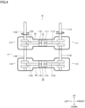
- Fig. 4 is a cross-sectional view of a part of the engine 11 of the flight device 10 according to another embodiment.
- the engine 11 illustrated in Fig. 4 includes a third engine unit 113 and a fourth engine unit 114, in addition to the first engine unit 111 and the second engine unit 112. That is, the engine 11 includes four engine units.
- the above-described first rotor 141 is rotated by the first engine unit 111 and the third engine unit 113, and the above-described second rotor 142 is rotated by the second engine unit 112 and the fourth engine unit 114.
- the flight device 10 illustrated in Fig. 4 is the same as that illustrated in Fig. 1 except for the configuration of the engine 11.
- the third engine unit 113 and the fourth engine unit 114 face each other along the right-left direction.
- the third engine unit 113 includes a third piston 1131, a third crankshaft 1132, and a third connecting rod 1133, which rotatably connects the third piston 1131 and the third crankshaft 1132.
- the third crankshaft 1132 of the third engine unit 113 continues to the first crankshaft 1112 of the first engine unit 111 in an integrated manner.
- the fourth engine unit 114 includes a fourth piston 1141, a fourth crankshaft 1142, and a fourth connecting rod 1143, which rotatably connects the fourth piston 1141 and the fourth crankshaft 1142.
- the fourth crankshaft 1142 of the fourth engine unit 114 continues to the second crankshaft 1122 of the second engine unit 112 in an integrated manner.
- the third piston 1131 and the fourth piston 1141 reciprocate within a cylinder 26.
- the third piston 1131 and the fourth piston 1141 share a combustion chamber 20.
- the third engine unit 113 performs the intake, compression, combustion, and exhaust strokes in synchronization with the first engine unit 111.
- the fourth engine unit 114 performs the intake, compression, combustion, and exhaust strokes in synchronization with the second engine unit 112.
- the third engine unit 113 and the fourth engine unit 114 are used as a power source in addition to the first engine unit 111 and the second engine unit 112, thus increasing the output of the rotors 14.
- Fig. 5 is a side view of a flight device 27 according to still another embodiment.
- the flight device 27 is a fixed-wing propeller aircraft having wings fixed to the fuselage.
- the flight device 27 includes the rotors 14 at the tip of the airframe.
- the rotors 14 are rotationally driven by the engine 11 arranged at the front end of the airframe.
- the configuration of the constituent units that drive the engine 11 and the rotors 14 are the same as that of the flight device 10 described above.
- Providing the engine 11 for the flight device 27 reduces vibrations and torque generated by the engine 11 running, thus improving the stable flight and comfortability of the flight device 27.
- the first drive transmission unit 22 and the second drive transmission unit 23 include the belts but can have different drive transmission mechanisms.
- the first drive transmission unit 22 and the second drive transmission unit 23 can include a gear train or the like.
- the flight device 10 is a parallel-type hybrid drone but may be an engine-type drone that only includes the rotors 14 but not the sub-rotors 15.
- the orientation control of the flight device 10 during flight can be implemented by pitch control of the rotors 14.
Landscapes
- Engineering & Computer Science (AREA)
- Aviation & Aerospace Engineering (AREA)
- Mechanical Engineering (AREA)
- Chemical & Material Sciences (AREA)
- Combustion & Propulsion (AREA)
- Transmission Devices (AREA)
Abstract
Description
- The present invention relates to a flight device and specifically relates to a flight device in which the rotor is driven by an engine.
- Flight devices capable of unmanned flight in the air have been known. Such a flight device is able to fly in the air using the thrust of a rotor rotating about a vertical axis.
- Application fields of such flight devices include the field of transportation, the field of surveying, and the field of photography, for example. In the case of applying the flight devices to such fields, surveying equipment and photography equipment are attached to the flight devices. When the flight devices are applied to such fields, the flight devices can fly in areas that human cannot access and perform transportation, photographing, and surveying of such areas. Inventions relating to such flight devices are described in
Patent Literature 1 and Patent Literature 2, for example. - In a typical flight device, the aforementioned rotor rotates using electric power supplied from a storage battery mounted on the flight device. However, energy supply by the electric power of the storage battery may not always be sufficient. In order to implement a continuous flight over a long period of time, flight devices equipped with engines also have emerged. In such a flight device, a generator is rotated using driving force of the engine, and the rotor is rotationally driven using electric power generated by the generator. In flight devices having such a configuration, the engine and the generator are connected in series on a path of energy supplied from the power source to the rotor. Such a flight device is therefore called a series-type drone. Use of such flight devices enables photography and surveying of wide areas. A flight device equipped with an engine is described in Patent Literature 3, for example. Furthermore, parallel-type hybrid drones are also gradually emerging, in which the main rotor is mechanically rotated using the driving force of the engine and a sub-rotor is rotated using a motor.
-
- Patent Literature 1:
Japanese Unexamined Patent Application Publication No. 2012-51545 - Patent Literature 2:
Japanese Unexamined Patent Application Publication No. 2014-240242 - Patent Literature 3:
Japanese Unexamined Patent Application Publication No. 2011-251678 - However, the conventional flight devices described above still have a room for improvement in the driving system mechanism.
- Specifically, many drones, as existing flight devices, include plural motors or engines, and because of remaining vibrations or anti-torque due to engines, it is difficult to accurately control the position and orientation of drones in the air. Furthermore, remaining vibrations or anti-torque due to generators also causes a similar problem.
- To solve these problems, a gear box or the like may be provided in the drive transmission system. However, such a configuration will increase the complexity of the overall structure of the drone and increase its weight, thus reducing the continuous flight time of the drone.
- The counter-torque generated by rotors can be cancelled out by employing coaxial rotors. However, in such cases, the aforementioned problems will become more obvious.
- The present invention was made in the light of the aforementioned circumstances, and an object thereof is to provide a flight device in which vibrations and anti-torque generated during flight are effectively reduced.
- A flight device of the present invention includes an engine, a transmission shaft, and a rotor, the engine includes a first engine unit and a second engine unit, the transmission shaft includes a first transmission shaft rotated by the first engine unit and a second transmission shaft rotated by the second engine unit, the rotor includes a first rotor rotated by the first transmission shaft and a second rotor rotated by the second transmission shaft, the first transmission shaft has a hollow structure, and the second transmission shaft is arranged inside the first transmission shaft.
- In the flight device of the present invention, the first engine unit and the second engine unit are arranged to face each other.
- In the flight device of the present invention, the first engine unit includes a first piston, a first crankshaft, and a first connecting rod rotatably connecting the first piston and the first crankshaft, the second engine unit includes a second piston, a second crankshaft, and a second connecting rod rotatably connecting the second piston and the second crankshaft, the first transmission shaft and the first crankshaft are drivingly connected with a first drive transmission unit interposed therebetween, and the second transmission shaft and the second crankshaft are drivingly connected with a second drive transmission unit interposed therebetween.
- In the flight device of the present invention, the engine further includes a third engine unit and a fourth engine unit, the first rotor is rotated by the first engine unit and the third engine unit, and the second rotor is rotated by the second engine unit and the fourth engine unit.
- In the flight device of the present invention, the first crankshaft and the second crankshaft rotate in opposite directions.
- The flight device of the present invention further includes a first generator and a second generator, the first generator is driven by the first engine unit, and the second generator is driven by the second engine unit.
- The flight device of the present invention further includes a sub-rotor, wherein
the sub-rotor is rotationally driven by a motor. - A flight device of the present invention includes an engine, a transmission shaft, and a rotor, in which the engine includes a first engine unit and a second engine unit, the transmission shaft includes a first transmission shaft rotated by the first engine unit and a second transmission shaft rotated by the second engine unit, the rotor includes a first rotor rotated by the first transmission shaft and a second rotor rotated by the second transmission shaft, the first transmission shaft has a hollow structure, and the second transmission shaft is arranged inside the first transmission shaft. According to the flight device of the present invention, the engine includes the first engine unit and the second engine unit, so that vibrations and torque generated by the engine units cancel each other out. This reduces vibrations and the like generated by the engine during flight, thus stabilizing the position and orientation during flight.
- Furthermore, in the flight device of the present invention, the first engine unit and the second engine unit are arranged to face each other. According to the flight device of the present invention, the first engine unit and the second engine unit are arranged to face each other, so that the effect of cancelling vibrations, torque, or the like each other out can be further enhanced.
- Still furthermore, in the flight device of the present invention, the first engine unit includes a first piston, a first crankshaft, and a first connecting rod rotatably connecting the first piston and the first crankshaft, the second engine unit includes a second piston, a second crankshaft, and a second connecting rod rotatably connecting the second piston and the second crankshaft, the first transmission shaft and the first crankshaft are drivingly connected with a first drive transmission unit interposed therebetween, and the second transmission shaft and the second crankshaft are drivingly connected with a second drive transmission unit interposed therebetween. According to the flight device of the present invention, the members of the first engine unit and the members of the second engine unit are arranged so as to face each other. This can extremely minimize vibrations and the like generated by running of the first engine unit and the second engine unit.
- Still furthermore, in the flight device of the present invention, the engine further includes a third engine unit and a fourth engine unit, the first rotor is rotated by the first engine unit and the third engine unit, and the second rotor is rotated by the second engine unit and the fourth engine unit. According to the flight device of the present invention, use of the third engine unit and the fourth engine unit as a power source in addition to the third engine unit and the fourth engine unit can improve the output of the rotor.
- Still furthermore, in the flight device of the present invention, the first crankshaft and the second crankshaft rotate in opposite directions. According to the flight device of the present invention, the rotation direction of the first crankshaft is opposite to that of the second crankshaft, so that the moments generated by rotation of the rotor cancel each other out. This can further improve the stability during flight.
- Still furthermore, the flight device of the present invention further includes a first generator and a second generator, in which the first generator is driven by the first engine unit and the second generator is driven by the second engine unit. According to the flight device of the present invention, driving the first generator and the second generator can produce electric energy necessary for flight.
- Still furthermore, the flight device of the present invention further includes a sub-rotor, in which the sub-rotor is rotationally driven by a motor. According to the flight device of the present invention, it is therefore possible to more effectively control the position and orientation during flight due to the sub-rotor.
-
- [
Fig. 1] Fig. 1 is a plan view of a flight device according to an embodiment of the present invention. - [
Fig. 2] Fig. 2 is a cross-sectional view of the flight device according to the embodiment of the present invention. - [
Fig. 3] Fig. 3 is a block diagram illustrating the connection configuration of the flight device according to the embodiment of the present invention. - [
Fig. 4] Fig. 4 is a cross-sectional view of a part of the flight device according to another embodiment of the present invention. - [
Fig. 5] Fig. 5 is a side view of a flight device according to still another embodiment of the present invention. - Hereinafter, the configuration of a flight device of embodiments will be described with reference to the drawings. In the following description, portions having the same configurations are denoted by the same reference numerals, and the description thereof will not be repeated. The following description will use up, down, front, back, right, and left directions, but these directions are for convenience of explanation. A
flight device 10 is also called a drone and specifically also called a parallel-type hybrid drone. The parallel-type hybrid drone is a drone including a rotor mechanically driven by an engine and a rotor driven by a motor. -
Fig. 1 is a plan view of theflight device 10 as seen from above. - The
flight device 10 mainly includes anengine 11, atransmission shaft 12, androtors 14. Theflight device 10 is a parallel-type hybrid drone including two driving systems in parallel, an electric driving system and a mechanical driving system. The electric driving system is a driving system that rotatesmotors 21 andsub-rotors 15, which will be described later. The mechanical driving system is a driving system that rotates therotors 14, which will be described later. - The
airframe 19 is a body supporting the units constituting thefright device 10 and is made of synthetic resin, metal, or a composite material thereof. - The
rotors 14 rotate to generate driving force necessary for theairframe 19 to float. Therotors 14 include afirst rotor 141 and asecond rotor 142. Thefirst rotor 141 and thesecond rotor 142 constitute a contra-rotating propeller. Thefirst rotor 141 and thesecond rotor 142 rotate in opposite directions at the same rotational speed. For example, in top view, thefirst rotor 141 rotates counterclockwise while thesecond rotor 142 rotates clockwise. Therotors 14 are main rotors mechanically rotated by driving force of theengine 11. - The
flight device 10 includes the sub-rotors 15. The sub-rotors 15 includesub-rotors 151 to 154. The sub-rotors 15 rotate to control the position and orientation of theflight device 10 during flight. - The sub-rotor 151 is positioned at the front left of the
airframe 19 and is rotated by amotor 211, which will be described later. The sub-rotor 152 is positioned at the back left of theairframe 19 and is rotated by amotor 212, which will be described later. The sub-rotor 153 is positioned at the front right of theairframe 19 and is rotated by amotor 213, which will be described later. The sub-rotor 154 is positioned at the back right of theairframe 19 and is rotated by amotor 214, which will be described later. -
Fig. 2 is a cross-sectional view of theflight device 10. - In the
flight device 10, theengine 11 is accommodated within theairframe 19, and therotors 14 are provided above theairframe 19. - The
engine 11 includes afirst engine unit 111 and asecond engine unit 112. - The
first engine unit 111 includes afirst piston 1111, afirst crankshaft 1112, and a first connectingrod 1113, which rotatably connects thefirst piston 1111 and thefirst crankshaft 1112. Thefirst crankshaft 1112 of thefirst engine unit 111 protrudes upward from the upper surface of theairframe 19. - The
second engine unit 112 includes asecond piston 1121, asecond crankshaft 1122, and a second connectingrod 1123, which rotatably connects thesecond piston 1121 and thesecond crankshaft 1122. Thesecond crankshaft 1122 of thesecond engine unit 112 protrudes upward from the upper surface of theairframe 19. - The
first piston 1111 of thefirst engine unit 111 and thesecond piston 1121 of the second engine unit 41 share acombustion chamber 13. In other words, thefirst piston 1111 and thesecond piston 1121 reciprocate within a single continuingcylinder 25. By thefirst piston 1111 and thesecond piston 1121 simultaneously making stroke toward the center, it is possible to achieve a high expansion ratio of gas mixture in thecombustion chamber 13 while reducing the stroke amount. - The
engine 11 includes a volume space (not illustrated herein) communicating with thecombustion chamber 13. In the volume space, a spark plug is arranged. In thecombustion chamber 13, an intake port and an exhaust port, which are not illustrated herein, are formed. An air-mixture containing fuel, such as gasoline, is introduced into thecombustion chamber 13 through the intake port, and exhaust gas after combustion is discharged from thecombustion chamber 13 to the outside through the exhaust port. - The
engine 11 configured as described above operates as follows. First, in an intake stroke, thefirst piston 1111 and thesecond piston 1121 move outward from the center within thecylinder 25 to introduce air mixture, as a mixture of air and fuel, into thecylinder 25. Next, in a compression stroke, thefirst piston 1111 and thesecond piston 1121 are forced toward the center due to inertia of the first andsecond crankshafts cylinder 25. Then, in a combustion stroke, the not-illustrated spark plug ignites in thecombustion chamber 13, and the air mixture burns within thecylinder 25. Thefirst piston 1111 and thesecond piston 1121 are thereby forced to the respective outer ends, which are bottom dead centers. Then, in an exhaust stroke, thefirst piston 1111 and thesecond piston 1121 are forced inward due to inertia of the first andsecond crankshafts cylinder 25 after combustion is discharged to the outside. - In the
engine 11, the two first andsecond pistons single cylinder 25, can share strokes. Compared to typical gasoline engines, therefore, the compression ratio of gas mixture can be increased. Since thefirst piston 1111 and thesecond piston 1121 face each other within thecylinder 25, theengine 11 does not need a cylinder head that is necessary for general engines. Theengine 11 therefore has a simple structure and light weight. The members constituting theengine 11, that is, the first andsecond pistons second crankshafts engine 11 are thereby canceled each other, so that vibrations generated by theentire engine 11 and transmitted to the outside can be reduced. The torque and the moments generated by rotation of the members constituting theengine 11 is almost all canceled. - By mounting the thus-configured
engine 11 on theflight device 10, theflight device 10 can be reduced in size, weight, vibrations, and reduction of counter-torque. Due to the reduction in vibrations in particular, it is possible to prevent delicate equipment, such as arithmetic control devices and GPS sensors, from being adversely affected by orientation control or motor output control. Furthermore, it is possible to prevent parcels being transported by theflight device 10 from being damaged by vibrations. - The
engine 11 is provided with a counter-rotation synchronization mechanism not illustrated herein. The counter-rotation synchronization mechanism causes thefirst crankshaft 1112 and thesecond crankshaft 1122 to rotate in opposite directions. Furthermore, the counter-rotation synchronization mechanism synchronizes reciprocating motions of thefirst piston 1111 and thesecond piston 1121. In theengine 11, therefore, thefirst crankshaft 1112 and thesecond crankshaft 1122 rotate in opposite directions in principle. The members drivingly connected to thefirst crankshaft 1112 and the members drivingly connected to thesecond crankshaft 1122 therefore rotate in opposite directions without a special reversing mechanism. Thefirst rotor 141 and thesecond rotor 142, which are illustrated inFig. 2 , therefore rotate in opposite directions at the same rotational speed without any special reversing mechanism. The other members rotationally driven by thefirst crankshaft 1112 and thesecond crankshaft 1122 rotate in opposite directions at the same rotational speed without any special reversing mechanism. - The
first generator 161 is arranged above theairframe 19 and is rotationally driven by thefirst crankshaft 1112. Specifically, thefirst generator 161 includes a not-illustrated rotor, and this rotor is connected to thefirst crankshaft 1112 so as not to rotate relative to thefirst crankshaft 1112. With this configuration, the rotor incorporated in thefirst generator 161 rotates together with thefirst crankshaft 1112 to implement power generation of thefirst power generator 161, thus generating electric energy. - The
second generator 162 has the same configuration as thefirst generator 161. Specifically, thesecond generator 162 is arranged above theairframe 19 and is rotationally driven by thesecond crankshaft 1122. Thesecond generator 162 includes a not-illustrated rotor, and this rotor is connected to thesecond crankshaft 1122 so as not to rotate relative to thesecond crankshaft 1122. With this configuration, the rotor incorporated in thesecond generator 162 rotates together with thesecond crankshaft 1122 to implement power generation of thesecond power generator 162, thus generating electric energy. - The
transmission shaft 12 is a substantially shaft-like member that is rotated by the driving force generated by theengine 11 to rotate theaforementioned rotors 14. Thetransmission shaft 12 includes afirst transmission shaft 121, which is rotated by thefirst engine unit 111, and asecond transmission shaft 122, which is rotated by thesecond engine unit 112. Thetransmission shaft 12 includes mechanisms mechanically and coaxially rotated in opposite directions as described later. - The upper end of the
first transmission shaft 121 is connected to thefirst rotor 141, and thefirst rotor 141 is thereby rotated. Thefirst transmission shaft 121 is provided so as to rotate relative to the upper surface of theairframe 19. Lower-end part of thefirst transmission shaft 121 is drivingly connected to thefirst crankshaft 1112 with a first drive transmission unit 22 (described later) interposed therebetween. That is, the rotational driving force generated by thefirst engine unit 111 is transmitted through thefirst crankshaft 1112 and the firstdrive transmission unit 22 to thefirst transmission shaft 121. - The upper end of the
second transmission shaft 122 is connected to thesecond rotor 142, and thesecond rotor 142 is thereby rotated. The second rotor142 is provided so as to rotate relative to the upper surface of theairframe 19. Lower-end part of thesecond transmission shaft 122 is drivingly connected to thesecond crankshaft 1122 with a second drive transmission unit 23 (described later) interposed therebetween. That is, the rotational driving force generated by thesecond engine unit 112 is transmitted through thesecond crankshaft 1122 and the second drive transmission unit 23 to thesecond transmission shaft 122. - The
first transmission shaft 121 has a hollow structure, and thesecond transmission shaft 122 is arranged inside thefirst transmission shaft 121. Specifically, a substantially cylindrical space is formed inside thefirst transmission shaft 121, and thesecond transmission shaft 122 penetrates the space. The upper end of thesecond transmission shaft 122 is positioned above the upper end of thefirst transmission shaft 121. Furthermore, the lower end of thesecond transmission shaft 122 is positioned below the lower end of thefirst transmission shaft 121. That is, thefist transmission shaft 121 and thesecond transmission shaft 122 constitute a coaxial contra-rotating structure. - The first
drive transmission unit 22 transmits the rotational driving force of thefirst crankshaft 1112 to thefirst transmission shaft 121. Specifically, the firstdrive transmission unit 22 includes a first engine-side pulley 221, afirst belt 222, and a first transmission shaft-side pulley 223. The first engine-side pulley 221 is connected to the upper end of thefirst crankshaft 1112 so as not to rotate relative to thefirst crankshaft 1112. The first transmission shaft-side pulley 223 is connected to the lower end of thefirst transmission shaft 121 so as not to rotate relative to thefirst transmission shaft 121. Thefirst belt 222 is laid over the first engine-side pulley 221 and the first transmission shaft-side pulley 223. With this configuration, at flight of theflight device 10, thefirst crankshaft 1112 and the first engine-side pulley 221 are rotated by of thefirst engine unit 111 running. Furthermore, the rotational driving force of the first engine-side pulley 221 is transmitted to the first transmission shaft-side pulley 223 through thefirst belt 222. Thefirst transmission shaft 121 and thefirst rotor 141 thereby rotate. - The second drive transmission unit 23 has the same configuration as the first
drive transmission unit 22. That is, the second drive transmission unit 23 transmits the rotational driving force of thesecond crankshaft 1122 to thesecond transmission shaft 122. Specifically, the second drive transmission unit 23 includes a second engine-side pulley 231, asecond belt 232, and a second transmission shaft-side pulley 233. The second engine-side pulley 231 is connected to the upper end of thesecond crankshaft 1122 so as not to rotate relative to thesecond crankshaft 1122. The second transmission shaft-side pulley 233 is connected to middle part of thesecond transmission shaft 122 so as not to rotate relative to thesecond transmission shaft 122. Thesecond belt 232 is laid over the second engine-side pulley 231 and the second transmission shaft-side pulley 233. With this configuration, at flight of theflight device 10, thesecond crankshaft 1122 and the second engine-side pulley 231 are rotated by thesecond engine unit 112 running. Furthermore, the rotational driving force of the second engine-side pulley 231 is transmitted to the second transmission shaft-side pulley 233 through thesecond belt 232. Thesecond transmission shaft 122 and thesecond rotor 142 thereby rotate. -
Fig. 3 is a block diagram illustrating the connection configuration of theflight device 10. - The
flight device 10 mainly includes thearithmetic control unit 17, theengine 11,generators 16, abattery 18, electricpower conversion units 24, themotors 21, and the sub-rotors 15. - The
arithmetic control unit 17 includes a CPU, a ROM, a RAM, and the like. Thearithmetic control unit 17 controls the behavior of each unit constituting theflight device 10 based on inputs from various sensors and a controller not illustrated herein. Thearithmetic control unit 17 serves as a flight controller that controls the rotational speed of therotors 14 andsub-rotors 15 based on inputs from various sensors. - The
engine 11 operates based on input signals from thearithmetic control unit 17 and generates kinetic energy necessary for theflight device 10 to fly. - The
generators 16 are units that generate electric power by using a part of the driving force of theengine 11 and include first andsecond generators first generator 161 is driven by thefirst engine unit 111 of theengine 11, which will be described above. Thesecond generator 162 is driven by thesecond engine unit 112 of theengine 11. - The
battery 18 is interposed between thegenerators 16 and the electricpower conversion units 24. Thebattery 18 is charged by thegenerators 16. The electric power discharged from thebattery 18 is supplied to the electricpower conversion units 24, which will be described later. - The electric
power conversion units 24 are provided corresponding to therespective sub-rotors 15. Eachpower conversion unit 24 can be composed of a converter and an inverter to once convert alternating-current power supplied from thesecond generator 162 into direct-current power and then convert the direct-current power into alternating-current power with a predetermined frequency. Each electricpower conversion unit 24 also can be composed of an inverter to convert direct-current power supplied from thebattery 18 into alternating-current power with a predetermined frequency. Specifically, the electricpower conversion units 24 include electricpower conversion units - The
motors 21 are provided corresponding to therespective sub-rotors 15. Themotors 21 includemotors motors power conversion units 241 to 244, respectively. - The sub-rotors 15 include the
sub-rotors 151 to 154 as described above. Thesub-rotors 151 to 154 are rotated by themotors 211 to 214, respectively. - The flight status of the
flight device 10 will be briefly described. Theflight device 10 is operated in a landing state, a takeoff state, a hovering state, an ascending-descending state, a horizontal movement state, and an emergency flight state. - In the landing state, the
flight device 10 is in contact with the ground. In this state, theengine 11 is not running, and therotors 14 do not rotate. - In the takeoff state, the
flight device 10 is rising away from the contact surface mainly due to the thrust generated by rotation of therotors 14. - In the hovering state, based on an instruction from the
arithmetic control unit 17, therotors 14 are rotated by driving force generated by theengine 11 to keep theflight device 10 floating at a predetermined position in the air. In this process, the sub-rotors 15 are rotating based on an instruction from thearithmetic control unit 17. Thearithmetic control unit 17 controls the electricpower conversion units 24 to set the rotational speeds of themotors 21 andsub-rotors 15 to predetermined values so that theflight device 10 can maintain its predetermined altitude and orientation. - In the ascending-descending state, the rotational speed of the
engine 11 is controlled to raise or lower theflight device 10. In this process as well, thearithmetic control unit 17 controls the electricpower conversion units 24 to set the rotational speeds of themotors 21 andsub-rotors 15 to predetermined values so that theflight device 10 can maintain its predetermined altitude and orientation. - In the horizontal movement state, the
arithmetic control unit 17 controls the electricpower conversion units 24 to control the rotational speeds of themotors 21 andsub-rotors 15 so that theflight device 10 be tilted. In this process as well, thearithmetic control unit 17 controls the running state of theengine 11 to rotate therotors 14 at a predetermined speed. - In the emergency flight state, the
arithmetic control unit 17 forces theflight device 10 that is flying to land. -
Fig. 4 is a cross-sectional view of a part of theengine 11 of theflight device 10 according to another embodiment. Theengine 11 illustrated inFig. 4 includes athird engine unit 113 and afourth engine unit 114, in addition to thefirst engine unit 111 and thesecond engine unit 112. That is, theengine 11 includes four engine units. The above-describedfirst rotor 141 is rotated by thefirst engine unit 111 and thethird engine unit 113, and the above-describedsecond rotor 142 is rotated by thesecond engine unit 112 and thefourth engine unit 114. Theflight device 10 illustrated inFig. 4 is the same as that illustrated inFig. 1 except for the configuration of theengine 11. - The
third engine unit 113 and thefourth engine unit 114 face each other along the right-left direction. - The
third engine unit 113 includes athird piston 1131, athird crankshaft 1132, and a third connectingrod 1133, which rotatably connects thethird piston 1131 and thethird crankshaft 1132. Herein, thethird crankshaft 1132 of thethird engine unit 113 continues to thefirst crankshaft 1112 of thefirst engine unit 111 in an integrated manner. - The
fourth engine unit 114 includes afourth piston 1141, afourth crankshaft 1142, and a fourth connectingrod 1143, which rotatably connects thefourth piston 1141 and thefourth crankshaft 1142. Herein, thefourth crankshaft 1142 of thefourth engine unit 114 continues to thesecond crankshaft 1122 of thesecond engine unit 112 in an integrated manner. - The
third piston 1131 and thefourth piston 1141 reciprocate within acylinder 26. Thethird piston 1131 and thefourth piston 1141 share acombustion chamber 20. With this configuration, in the same manner as described above, it is possible to substantially completely remove the counter torque generated by thethird engine unit 113 and thefourth engine unit 114 running. Furthermore, thethird engine unit 113 performs the intake, compression, combustion, and exhaust strokes in synchronization with thefirst engine unit 111. Thefourth engine unit 114 performs the intake, compression, combustion, and exhaust strokes in synchronization with thesecond engine unit 112. - In the
flight device 10 illustrated inFig. 4 , thethird engine unit 113 and thefourth engine unit 114 are used as a power source in addition to thefirst engine unit 111 and thesecond engine unit 112, thus increasing the output of therotors 14. -
Fig. 5 is a side view of aflight device 27 according to still another embodiment. - The
flight device 27 is a fixed-wing propeller aircraft having wings fixed to the fuselage. Theflight device 27 includes therotors 14 at the tip of the airframe. Therotors 14 are rotationally driven by theengine 11 arranged at the front end of the airframe. The configuration of the constituent units that drive theengine 11 and therotors 14 are the same as that of theflight device 10 described above. - Providing the
engine 11 for theflight device 27 reduces vibrations and torque generated by theengine 11 running, thus improving the stable flight and comfortability of theflight device 27. - Hereinabove, the embodiment of the present invention is described. However, the present invention is not limited to the aforementioned embodiment and can be changed without departing from the spirit of the present invention. Furthermore, the aforementioned modes can be properly combined.
- In the example illustrated with reference to
Fig. 2 , the firstdrive transmission unit 22 and the second drive transmission unit 23 include the belts but can have different drive transmission mechanisms. For example, the firstdrive transmission unit 22 and the second drive transmission unit 23 can include a gear train or the like. - With reference to
Fig. 2 , theflight device 10 is a parallel-type hybrid drone but may be an engine-type drone that only includes therotors 14 but not the sub-rotors 15. In this case, the orientation control of theflight device 10 during flight can be implemented by pitch control of therotors 14. -
- 10
- FLIGHT DEVICE
- 11
- ENGINE
- 111
- FIRST ENGINE UNIT
- 1111
- FIRST PISTON
- 1112
- FIRST CRANKSHAFT
- 1113
- FIRST CONNECTING ROD
- 112
- SECOND ENGINE UNIT
- 1121
- SECOND PISTON
- 1122
- SECOND CRANKSHAFT
- 1123
- SECOND CONNECTING ROD
- 113
- THIRD ENGINE UNIT
- 1131
- THIRD PISTON
- 1132
- THIRD CRANKSHAFT
- 1133
- THIRD CONNECTING ROD
- 114
- FOURTH ENGINE UNIT
- 1141
- FOURTH PISTON
- 1142
- FOURTH CRANKSHAFT
- 1143
- FOURTH CONNECTING ROD
- 12
- TRANSMISSION SHAFT
- 121
- FIRST TRANSMISSION SHAFT
- 122
- SECOND TRANSMISSION SHAFT
- 13
- COMBUSTION CHAMBER
- 14
- ROTOR
- 141
- FIRST ROTOR
- 142
- SECOND ROTOR
- 15
- SUB-ROTOR
- 151
- SUB-ROTOR
- 152
- SUB-ROTOR
- 153
- SUB-ROTOR
- 154
- SUB-ROTOR
- 16
- GENERATOR
- 161
- FIRST GENERATOR
- 162
- SECOND GENERATOR
- 17
- ARITHMETIC CONTROL UNIT
- 18
- BATTERY
- 19
- AIRFRAME
- 20
- COMBUSTION CHAMBER
- 21
- MOTOR
- 211
- MOTOR
- 212
- MOTOR
- 213
- MOTOR
- 214
- MOTOR
- 22
- FIRST DRIVE TRANSMISSION UNIT
- 221
- FIRST ENGINE-SIDE PULLEY
- 222
- FIRST BELT
- 223
- FIRST TRANSMISSION SHAFT-SIDE PULLEY
- 23
- SECOND DRIVE TRANSMISSION UNIT
- 231
- SECOND ENGINE-SIDE PULLEY
- 232
- SECOND BELT
- 233
- SECOND TRANSMISSION SHAFT-SIDE PULLEY
- 24
- POWER CONVERSION UNIT
- 241
- POWER CONVERSION UNIT
- 242
- POWER CONVERSION UNIT
- 243
- POWER CONVERSION UNIT
- 244
- POWER CONVERSION UNIT
- 25
- CYLINDER
- 26
- CYLINDER
- 27
- FLIGHT DEVICE
Claims (7)
- A flight device comprising an engine, a transmission shaft, and a rotor, whereinthe engine includes a first engine unit and a second engine unit,the transmission shaft includes a first transmission shaft rotated by the first engine unit and a second transmission shaft rotated by the second engine unit,the rotor includes a first rotor rotated by the first transmission shaft and a second rotor rotated by the second transmission shaft,the first transmission shaft has a hollow structure, andthe second transmission shaft is arranged inside the first transmission shaft.
- The flight device according to claim 1, wherein
the first engine unit and the second engine unit are arranged to face each other. - The flight device according to claim 1 or 2, whereinthe first engine unit includes a first piston, a first crankshaft, and a first connecting rod rotatably connecting the first piston and the first crankshaft,the second engine unit includes a second piston, a second crankshaft, and a second connecting rod rotatably connecting the second piston and the second crankshaft,the first transmission shaft and the first crankshaft are drivingly connected with a first drive transmission unit interposed therebetween, andthe second transmission shaft and the second crankshaft are drivingly connected with a second drive transmission unit interposed therebetween.
- The flight device according to claim 1 or 2, whereinthe engine further includes a third engine unit and a fourth engine unit,the first rotor is rotated by the first engine unit and the third engine unit, andthe second rotor is rotated by the second engine unit and the fourth engine unit.
- The flight device according to claim 3, wherein the first crankshaft and the second crankshaft rotate in opposite directions.
- The flight device according to claim 1 or 2, further comprising a first generator and a second generator, whereinthe first generator is driven by the first engine unit, andthe second generator is driven by the second engine unit.
- The flight device according to claim 1 or 2, further comprising a sub-rotor, wherein
the sub-rotor is rotationally driven by a motor.
Applications Claiming Priority (2)
| Application Number | Priority Date | Filing Date | Title |
|---|---|---|---|
| JP2022065773A JP7810965B2 (en) | 2022-04-12 | 2022-04-12 | flight equipment |
| PCT/JP2023/013970 WO2023199801A1 (en) | 2022-04-12 | 2023-04-04 | Flying device |
Publications (2)
| Publication Number | Publication Date |
|---|---|
| EP4509403A1 true EP4509403A1 (en) | 2025-02-19 |
| EP4509403A4 EP4509403A4 (en) | 2026-01-21 |
Family
ID=88329601
Family Applications (1)
| Application Number | Title | Priority Date | Filing Date |
|---|---|---|---|
| EP23788220.4A Pending EP4509403A4 (en) | 2022-04-12 | 2023-04-04 | AIRCRAFT |
Country Status (4)
| Country | Link |
|---|---|
| US (1) | US20250033761A1 (en) |
| EP (1) | EP4509403A4 (en) |
| JP (2) | JP7810965B2 (en) |
| WO (1) | WO2023199801A1 (en) |
Families Citing this family (4)
| Publication number | Priority date | Publication date | Assignee | Title |
|---|---|---|---|---|
| JP6707761B2 (en) * | 2017-09-27 | 2020-06-10 | 株式会社石川エナジーリサーチ | Self-contained flight device with engine |
| JP7838755B2 (en) * | 2022-03-29 | 2026-04-01 | 株式会社石川エナジーリサーチ | flight equipment |
| JP7170364B1 (en) * | 2022-09-08 | 2022-11-14 | 株式会社石川エナジーリサーチ | flight device |
| EP4644271A1 (en) * | 2022-12-27 | 2025-11-05 | Kubota Corporation | Aerial vehicle |
Family Cites Families (16)
| Publication number | Priority date | Publication date | Assignee | Title |
|---|---|---|---|---|
| GB360167A (en) * | 1929-10-18 | 1931-11-05 | Fiat Spa | Improvements in propelling means for aircraft |
| US2174946A (en) * | 1935-04-02 | 1939-10-03 | Autogiro Co Of America | Autorotative-winged aircraft |
| DE3347679C2 (en) * | 1983-12-31 | 1985-11-14 | Sita Bauelemente Gmbh, 2080 Pinneberg | Double propeller |
| US5954479A (en) * | 1996-12-16 | 1999-09-21 | Smith; Ronald A. | Twin engine, coaxial, dual-propeller propulsion system |
| US7712701B1 (en) * | 2006-02-10 | 2010-05-11 | Lockheed Martin Corporation | Unmanned aerial vehicle with electrically powered, counterrotating ducted rotors |
| FR2961041B1 (en) | 2010-06-02 | 2012-07-27 | Parrot | METHOD FOR SYNCHRONIZED CONTROL OF ELECTRIC MOTORS OF A ROTARY WHEEL REMOTE CONTROL DRONE SUCH AS A QUADRICOPTERE |
| KR101042200B1 (en) | 2010-09-02 | 2011-06-16 | 드림스페이스월드주식회사 | Unmanned Vehicle Using a PC |
| JP2014240242A (en) | 2013-06-12 | 2014-12-25 | 富士重工業株式会社 | Vertical take-off and landing flight vehicle |
| US9701395B2 (en) * | 2014-01-06 | 2017-07-11 | United Technologies Corporation | Contra-rotating open rotor distributed propulsion system |
| RU2627220C1 (en) * | 2016-07-26 | 2017-08-04 | Общество с ограниченной ответственностью "АвиаНовации" | Vertical takeoff and landing aircraft |
| US11932380B2 (en) | 2017-03-15 | 2024-03-19 | Textron Innovations Inc. | Vibration isolation systems for compound helicopters |
| US9994305B1 (en) * | 2017-04-14 | 2018-06-12 | Swift Engineering, Inc. | Coaxial drive propulsion system for aerial vehicles, and associated systems and methods |
| JP6707761B2 (en) * | 2017-09-27 | 2020-06-10 | 株式会社石川エナジーリサーチ | Self-contained flight device with engine |
| CN211281442U (en) * | 2019-12-09 | 2020-08-18 | 北京海空行科技有限公司 | A coaxial helicopter manipulation-transmission system based on a single automatic tilter |
| JP6969821B2 (en) | 2020-01-17 | 2021-11-24 | 株式会社石川エナジーリサーチ | Self-contained flight device with engine |
| JP7133745B2 (en) | 2020-04-30 | 2022-09-08 | ヤマハ発動機株式会社 | Aircraft engine generator unit and aircraft |
-
2022
- 2022-04-12 JP JP2022065773A patent/JP7810965B2/en active Active
-
2023
- 2023-04-04 EP EP23788220.4A patent/EP4509403A4/en active Pending
- 2023-04-04 WO PCT/JP2023/013970 patent/WO2023199801A1/en not_active Ceased
-
2024
- 2024-10-09 US US18/910,473 patent/US20250033761A1/en active Pending
-
2026
- 2026-01-15 JP JP2026005323A patent/JP2026063191A/en active Pending
Also Published As
| Publication number | Publication date |
|---|---|
| JP2026063191A (en) | 2026-04-10 |
| US20250033761A1 (en) | 2025-01-30 |
| JP2023156106A (en) | 2023-10-24 |
| EP4509403A4 (en) | 2026-01-21 |
| JP7810965B2 (en) | 2026-02-04 |
| WO2023199801A1 (en) | 2023-10-19 |
Similar Documents
| Publication | Publication Date | Title |
|---|---|---|
| JP7004369B1 (en) | Flight equipment | |
| US20250033761A1 (en) | Flight device | |
| EP4414263A1 (en) | Flight device | |
| US12428985B2 (en) | Engine-mounted autonomous flying device | |
| JP7399521B2 (en) | flight equipment | |
| US12441495B2 (en) | Flight device and flight device control method | |
| JP2019112050A (en) | Air vehicle | |
| JP7697745B1 (en) | flight equipment | |
| CN112550694B (en) | Vertical take-off and landing tilting wing aircraft based on hybrid electric propulsion system | |
| CN218537120U (en) | Double-propeller fixed wing unmanned aerial vehicle | |
| JP7438589B1 (en) | flight equipment | |
| CN116710359A (en) | aircraft | |
| CN120903038A (en) | Double-propeller foldable fixed wing unmanned aerial vehicle construction method | |
| RU2260546C1 (en) | Vertical takeoff and landing flying vehicle with aerodynamic lifting tractor-type propeller | |
| WO2025173191A1 (en) | Flying device | |
| CN109649649A (en) | Tiltrotor aircraft |
Legal Events
| Date | Code | Title | Description |
|---|---|---|---|
| STAA | Information on the status of an ep patent application or granted ep patent |
Free format text: STATUS: THE INTERNATIONAL PUBLICATION HAS BEEN MADE |
|
| PUAI | Public reference made under article 153(3) epc to a published international application that has entered the european phase |
Free format text: ORIGINAL CODE: 0009012 |
|
| STAA | Information on the status of an ep patent application or granted ep patent |
Free format text: STATUS: REQUEST FOR EXAMINATION WAS MADE |
|
| 17P | Request for examination filed |
Effective date: 20241031 |
|
| AK | Designated contracting states |
Kind code of ref document: A1 Designated state(s): AL AT BE BG CH CY CZ DE DK EE ES FI FR GB GR HR HU IE IS IT LI LT LU LV MC ME MK MT NL NO PL PT RO RS SE SI SK SM TR |
|
| DAV | Request for validation of the european patent (deleted) | ||
| DAX | Request for extension of the european patent (deleted) | ||
| A4 | Supplementary search report drawn up and despatched |
Effective date: 20251219 |
|
| RIC1 | Information provided on ipc code assigned before grant |
Ipc: B64C 27/10 20230101AFI20251215BHEP Ipc: B64C 25/10 20060101ALI20251215BHEP Ipc: B64C 25/24 20060101ALI20251215BHEP Ipc: B64C 39/02 20230101ALI20251215BHEP Ipc: B64D 27/24 20240101ALI20251215BHEP Ipc: B64U 10/16 20230101ALI20251215BHEP Ipc: B64U 30/24 20230101ALI20251215BHEP Ipc: B64U 50/11 20230101ALI20251215BHEP Ipc: B64U 50/23 20230101ALI20251215BHEP Ipc: B64D 35/06 20060101ALI20251215BHEP Ipc: B64U 50/33 20230101ALI20251215BHEP |