EP4509400A1 - Insulation blanket assemblies and methods - Google Patents
Insulation blanket assemblies and methods Download PDFInfo
- Publication number
- EP4509400A1 EP4509400A1 EP24192211.1A EP24192211A EP4509400A1 EP 4509400 A1 EP4509400 A1 EP 4509400A1 EP 24192211 A EP24192211 A EP 24192211A EP 4509400 A1 EP4509400 A1 EP 4509400A1
- Authority
- EP
- European Patent Office
- Prior art keywords
- insulation
- support rails
- aircraft
- insulation blanket
- blanket assembly
- Prior art date
- Legal status (The legal status is an assumption and is not a legal conclusion. Google has not performed a legal analysis and makes no representation as to the accuracy of the status listed.)
- Pending
Links
Images










Classifications
-
- B—PERFORMING OPERATIONS; TRANSPORTING
- B64—AIRCRAFT; AVIATION; COSMONAUTICS
- B64C—AEROPLANES; HELICOPTERS
- B64C1/00—Fuselages; Constructional features common to fuselages, wings, stabilising surfaces or the like
- B64C1/40—Sound or heat insulation, e.g. using insulation blankets
-
- B—PERFORMING OPERATIONS; TRANSPORTING
- B64—AIRCRAFT; AVIATION; COSMONAUTICS
- B64C—AEROPLANES; HELICOPTERS
- B64C1/00—Fuselages; Constructional features common to fuselages, wings, stabilising surfaces or the like
- B64C1/40—Sound or heat insulation, e.g. using insulation blankets
- B64C1/403—Arrangement of fasteners specially adapted therefor, e.g. of clips
-
- B—PERFORMING OPERATIONS; TRANSPORTING
- B64—AIRCRAFT; AVIATION; COSMONAUTICS
- B64F—GROUND OR AIRCRAFT-CARRIER-DECK INSTALLATIONS SPECIALLY ADAPTED FOR USE IN CONNECTION WITH AIRCRAFT; DESIGNING, MANUFACTURING, ASSEMBLING, CLEANING, MAINTAINING OR REPAIRING AIRCRAFT, NOT OTHERWISE PROVIDED FOR; HANDLING, TRANSPORTING, TESTING OR INSPECTING AIRCRAFT COMPONENTS, NOT OTHERWISE PROVIDED FOR
- B64F5/00—Designing, manufacturing, assembling, cleaning, maintaining or repairing aircraft, not otherwise provided for; Handling, transporting, testing or inspecting aircraft components, not otherwise provided for
- B64F5/10—Manufacturing or assembling aircraft, e.g. jigs therefor
Definitions
- the present disclosure generally relates to insulation, and more particularly, to support rails for aircraft insulation blankets.
- Aircrafts use thermal and acoustic insulation for different purposes.
- thermal and acoustic insulation can be used to reduce noise transfer and thermal conduction with outside elements of an aircraft.
- thermal and acoustic insulation can be used to channel moisture generated in an upper lobe cabin of the aircraft down to drains in a lower lobe structure of the aircraft, where the moisture exits the aircraft.
- thermal and acoustic insulation can become saturated from the moisture and can block water on its way along a drain path.
- the present application is directed to reducing a rate at which an insulation blanket becomes saturated on an aircraft.
- one or more support rails are attached to, or embedded within, the insulation blanket to provide separation between an insulation material of the insulation blanket and an aircraft structure, such as a fuselage panel, to reduce or eliminate moisture associated with the aircraft structure from saturating the insulation material.
- Moisture generated in an upper lobe of the aircraft is typically channeled down to drains in a lower lobe structure of the aircraft, from which the moisture exits the aircraft.
- moisture typically collects near a lower lobe cheek and bilge of the aircraft before exiting the aircraft.
- the lower lobe cheek and bilge of the aircraft can be a relatively wet environment.
- the insulation blanket can be used to channel moisture from the upper lobe of the aircraft down to the drains in the lower lobe structure of the aircraft.
- one or more support rails are attached to, or embedded within, the insulation blanket to provide separation between the insulation material and different aircraft structures (e.g., to prevent the insulation material from laying flush against skin and structure in the lower lobe structure of the aircraft).
- the one or more support rails can be made of a foam material.
- the foam support rails allow water drainage above and below the surface of the insulation blanket.
- the one or more support rails may be comprised of a closed cell foam to reduce or eliminate moisture absorption.
- the increased gap between the insulation material and the lower lobe structure of the aircraft can prevent the insulation material within the insulation blanket from becoming saturated with moisture, thus increasing the in-service performance of the insulation blanket.
- the cover has an inboard material and an outboard material.
- the insulation blanket assembly also includes an insulation material between the inboard material and the outboard material.
- the insulation blanket assembly also includes one or more support rails attached to at least one of the cover or the insulation material. When the insulation blanket assembly is attached to the aircraft, the one or more support rails are configured to provide separation between an aircraft structure and the insulation material to reduce or eliminate moisture from transferring to the insulation material.
- the present application discloses an aircraft.
- the aircraft includes a fuselage.
- the fuselage includes a plurality of frame structures and a plurality of stringers attached to the plurality of frame structures.
- the plurality of stringers extend laterally along a length of the fuselage.
- the aircraft also includes an insulation blanket assembly attached to at least one frame structure of the plurality of frame structures or to at least one stringer of the plurality of stringers.
- the insulation blanket assembly includes one or more support rails that extend transverse relative to the plurality of stringers.
- the present application discloses a method of making an insulation blanket assembly for an aircraft.
- the method includes providing an insulation material.
- the method also includes forming a cover.
- the method also includes, prior to or after forming the cover, attaching one or more support rails to at least one of the cover or the insulation material such that, when installed on the aircraft, the one or more support rails provide separation of the insulation material from an outer panel of the aircraft for moisture management.
- the present application discloses a method of installing an insulation blanket assembly on an aircraft.
- the method includes applying (i) first hook tape to a first inner mold line of a first aircraft frame structure and (ii) second hook tape to a second inner mold line of a second aircraft frame structure.
- the first hook tape and the first hook tape are double-sided tapes.
- the method also includes applying (i) first loop tape to a first group of blanket tabs attached to a first edge of an outboard material of an insulation blanket assembly and (ii) second loop tape to a second group of blanket tables attached to a second edge of the outboard material.
- the first loop tape and the second loop tape are double-sided tapes
- the insulation blanket assembly comprises one or more support rails that extend transverse relative to aircraft stringers.
- the method also includes attaching (i) the first group of blanket tabs to the first inner mold line by placing the first loop tape on top of the first hook tape and (ii) the second group of blanket tabs to the second inner mold line by placing the second loop tape on top of the second hook tape.
- the distinguishing letter "A" is used.
- the reference number 100 may be used without a distinguishing letter.
- an ordinal term e.g., "first,” “second,” “third,” etc.
- an element such as a structure, a component, an operation, etc.
- the term “set” refers to a grouping of one or more elements
- the term “plurality” refers to multiple elements.
- FIG. 1A a diagram of an insulation blanket assembly 100A that includes one or more support rails is illustrated, according to an exemplary embodiment. According to some implementations, as described in greater detail with respect to Figure 2 , the insulation blanket assembly 100A can be installed on an aircraft 200.
- the insulation blanket assembly 100A includes a cover 101A having an outboard material 102A and an inboard material 104A.
- the insulation blanket assembly 100A also includes an insulation material 110A between the inboard material 104A and the outboard material 102A.
- the outboard material 102A of the cover 101A is wrapped around a first side of the insulation material 110A
- the inboard material 104A of the cover 101A is wrapped around a second side of the insulation material 110A.
- An edge of the inboard material 104A is attached to an edge of the outboard material 102A via tape 103A.
- the insulation blanket assembly 100A also includes one or more support rails 106A attached to the cover 101A.
- the one or more support rails 106A are attached to the outboard material 102A of the cover 101A such that the outboard material 102A is between the insulation material 110A and the one or more support rails 106A.
- the one or more support rails 106A may be attached with double-sided tape or a garment tags.
- the one or more support rails 106A are configured to provide separation between an aircraft structure (e.g., such as an aircraft stringer or an aircraft fuselage structure) and the insulation material 110A to reduce or eliminate moisture from transferring to the insulation material 110A.
- an aircraft structure e.g., such as an aircraft stringer or an aircraft fuselage structure
- each support rail 106A of the one or more support rails 106A may include an elongated member that has a length that is less than a length of the cover 101A such that ends of the one or more support rails 106A are separated laterally from a perimeter of the cover 101A.
- the insulation blanket assembly 100A includes two (2) support rails 106A that extend in a parallel direction relative to each other.
- the insulation blanket assembly 100A can include additional (or fewer) support rails 106A.
- the insulation blanket assembly 100A can include five (5) support rails 106A extended in a parallel direction relative to each other.
- the support rails 106A may be comprised of a flexible material to enable the support rails 106A to be flexible.
- the support rails 106A may be comprised of a foam material.
- a first support rail 106A of the one or more support rails 106A has a first length
- a second support rail 106A of the one or more support rails 106A has a second length that is less than the first length to provide variable rigidity along the insulation blanket assembly 100A.
- a first support rail 106A of the one or more support rails 106 has a first width
- a second support rail 106A of the one or more support rails 106A has a second width that is less than the first width.
- the first and second support rails 106A may be comprised of the same foam material such that the first support rail 106A has a different stiffness than the second support rail 106A to provide rigidity to the insulation blanket assembly 100A.
- the insulation blanket assembly 100 may also include a plurality of attachment portions 172.
- Each attachment portion 172 includes a hole that extends through the cover 101A and the insulation material 110A to facilitate attachment of the insulation blanket assembly 100A to an aircraft structure with a fastener.
- At least one support rail 106A of the one or more support rails 106A is an elongated member that includes a beveled edge 107A on opposing ends of the elongated member to facilitate sliding the insulation blanket assembly 110A into position prior to securing the insulation blanket assembly 110A to an aircraft structure.
- at least one support rail 106A of the one or more support rails 106A is an elongated member that includes a straight edge 108A.
- Figure 1A illustrates one support rail 106A having the beveled edge 107A and one support rail 106A having the straight edge 108A
- the edges of the support rails 106A can be consistent for the insulation blanket assembly 100A.
- each support rail 106A can have the beveled edge 107A or each support rail 106A can have the straight edge 108A.
- FIG. 1E another diagram of an insulation blanket assembly 100B that includes one or more support rails is illustrated, according to an exemplary embodiment. According to some implementations, as described in greater detail with respect to Figure 2 , the insulation blanket assembly 100B can be installed on the aircraft 200.
- the insulation blanket assembly 100B includes a cover 101B having an outboard material 102B and an inboard material 104B.
- the insulation blanket assembly 100B also includes an insulation material 110B between the inboard material 104B and the outboard material 102B.
- the outboard material 102B of the cover 101B is wrapped around a first side of the insulation material 110B
- the inboard material 104B of the cover 101B is wrapped around a second side of the insulation material 110B.
- An edge of the inboard material 104B is attached to an edge of the outboard material 102B via tape 103B.
- the insulation blanket assembly 100F also includes one or more support rails 106B attached to the insulation material 110B.
- the one or more support rails 106B are attached to the insulation material 110B such that the one or more support rails 106B are positioned between the outboard material 102B and the insulation material 110B.
- the one or more support rails 106B may be attached with double-sided tape.
- the one or more support rails 106B are configured to provide separation between an aircraft structure (e.g., such as an aircraft stringer or an aircraft fuselage structure) and the insulation material 110B to reduce or eliminate moisture from transferring to the insulation material 110B.
- an aircraft structure e.g., such as an aircraft stringer or an aircraft fuselage structure
- each support rail 106B of the one or more support rails 106B may include an elongated member that has a length that is less than a length of the cover 101B such that ends of the one or more support rails 106B are separated laterally from a perimeter of the cover 101B.
- the insulation blanket assembly 100B includes two (2) support rails 106B that extend in a parallel direction relative to each other.
- the insulation blanket assembly 100B can include additional (or fewer) support rails 106B.
- the insulation blanket assembly 100B can include five (5) support rails 106B extended in a parallel direction relative to each other.
- the support rails 106B may be comprised of a flexible material to enable the support rails 106B to be flexible.
- the support rails 106B may be comprised of a foam material.
- a first support rail 106B of the one or more support rails 106B has a first length
- a second support rail 106B of the one or more support rails 106B has a second length that is less than the first length to provide variable rigidity along the insulation blanket assembly 100B.
- a first support rail 106B of the one or more support rails 106B has a first width
- a second support rail 106B of the one or more support rails 106B has a second width that is less than the first width.
- the first and second support rails 106B may be comprised of the same foam material such that the first support rail 106B has a different stiffness than the second support rail 106B to provide rigidity to the insulation blanket assembly 100B.
- the insulation blanket assembly 100B may also include a plurality of attachment portions 172.
- Each attachment portion 172 includes a hole that extends through the cover 101B and the insulation material 110B to facilitate attachment of the insulation blanket assembly 100B to an aircraft structure with a fastener.
- At least one support rail 106B of the one or more support rails 106B is an elongated member that includes a beveled edge 107B on opposing ends of the elongated member to facilitate sliding the insulation blanket assembly 110B into position prior to securing the insulation blanket assembly 110B to an aircraft structure.
- stiffeners e.g., support rails
- multiple stiffener cross sections can be utilized according to the techniques described herein.
- a rectangular stiffener may be used for simplicity; however, a triangle stiffener may add rigidity for higher fabrication costs.
- multiple rectangular stiffeners may be laminated together in a leaf spring pattern and preloaded with curvature for added stiffness with no additional weight expense.
- Figure 2 illustrates a cross-sectional, schematic view of an aircraft 200 that includes an insulation blanket assembly, according to an exemplary embodiment.
- Figure 2 depicts a fuselage 230 of the aircraft 200.
- the fuselage 230 includes a floor 204, a ceiling 206, and an aesthetic fascia wall or an inner wall 208 that defines a cabin 202, where the ceiling 206 and/or the inner wall 208 represents an interior wall of the aircraft 200.
- the floor 204 of the cabin 202 may be supported by a plurality of supporting beams 260.
- the inner wall 208 is a lining that separates a main cabin, cockpit, and/or other areas within the aircraft 200 from the fuselage 230.
- the inner wall 208 can be made of plastic, glass-fiber, carbon fiber, glass-reinforced resin, other reinforced polymers, and/or other materials.
- the inner wall 208 can be designed to provide thermal and acoustic insulation as well.
- Passengers in the aircraft 200 may congregate in seats 210 of the cabin 202 during flight.
- Figure 2 illustrates that, inside of the fuselage 230 (e.g., in the cabin 202), respiration and other sources of water cause a moisture 220 to enter or form in the air in the cabin 202.
- warm exhaled air includes the moisture 220 and rises upward through the ceiling 206. Some of the warm air rises into a space 240 between an outer wall 216 of the aircraft 200 and the cabin 202.
- the temperature of the outer wall 216 eventually decreases to a temperature below a freezing temperature of water.
- This cooling causes the moisture 220 (e.g., water) to condense out of the air in the space 240 and freeze onto an interior surfaces of the outer wall 216 as ice.
- the ice begins to melt causing water droplets 225 (e.g., liquid) to travel through the space 240 towards a bottom of the fuselage 230.
- the space 240 can include one or more insulation blanket assemblies 100 to provide thermal and acoustic insulation to the aircraft 200.
- the insulation blanket assemblies 100 in Figure 2 can correspond to the insulation blanket assembly 100A of Figure 1A or the insulation blanket assembly 110B of Figure 1E .
- the support rails 106 of one of the insulation blanket assemblies 110 are proximate to (e.g., resting on) aircraft stringers 250 running along the outer wall 216 of the fuselage 230.
- the one or more support rails 106 may extend perpendicular relative to the stringers 250 such that the one or more support rails 106 provide a drainage path downwardly towards a lower area of the fuselage 230.
- the orientation of the support rails 106 is perpendicular to an orientation of the aircraft stringers 250 such that the support rails 106 can rest on the aircraft stringers 250 to provide separation between the insulation material 110 and an aircraft structure, such as the aircraft stringers 250 and/or the outer wall 216 of the fuselage 230.
- the support rails 106 of the other insulation blanket assembly 100 is resting flush on the outer wall 216 of the fuselage 230 to provide separation between the insulation material 110 and the outer wall 216.
- the support rails 106 reduce an amount of moisture transferred to the insulation material 110 as the water droplets 225 (e.g., liquid) travel through the space 240 towards the bottom of the fuselage 230.
- the separation between the insulation material 110 and the different aircraft structures caused by the support rails 106 enable the insulation material 110 to remain relatively dry, which decreases the rate at which the insulation material 110 becomes saturated and thus improves (e.g., lengthens) the lifespan of the insulation blanket assembly 100.
- the support rails 106 are flexible (e.g., comprised of a foam material)
- the support rails 106 can take the shape of the aircraft structures on which the insulation blanket assemblies 100 rest.
- the insulation blanket assembly 100 may radially conform to a shape of the fuselage 230 of the aircraft 200 when installed.
- Figure 3 illustrates a structural view of the aircraft fuselage 230 that includes the insulation blanket assembly 100, according to an exemplary embodiment.
- the aircraft fuselage 230 includes the floor 204 that is supported by the plurality of supporting beams 260.
- the supporting beams 260 can be coupled to (and supported by) a plurality of struts 302.
- the aircraft stringers 250 run along the side of the aircraft fuselage 230 and are supported by a plurality of circular frame structures 304.
- the plurality of stringers 250 may be attached to the plurality of frame structures 304 and may extend laterally along a length of the fuselage 230.
- the skin 306 of the aircraft 200 is coupled to the circular frame structures 304 and the aircraft stringers 250.
- the support rails 106 of the insulation blanket assembly 100 are positioned perpendicular to the orientation of the aircraft stringers 250.
- moisture e.g., the water droplets 225
- the configuration of the support rails 106 on the insulation blanket assembly 100 enable the insulation material 110 to be separated from the water droplets 225 as the droplets 225 travel downwardly, which also promotes vertical drainage of the water droplets 225.
- Figure 4A illustrates the insulation blanket assembly 100A that includes one or more support rails attached to an outboard material, according to an exemplary embodiment.
- the support rails 106A are attached to the outboard material 102A of the cover 101A such that the outboard material 102A is between the insulation material (not shown in Figure 4A ) and the support rails 106A.
- Figure 4B illustrates an insulation blanket assembly that includes one or more support rails attached to an insulation material, according to an exemplary embodiment.
- the support rail 106B is attached to the insulation material 110B via an adhesive 402, such as double-sided tape.
- the support rail 106B is between the insulation material 110B and the outboard material 102B of the cover 101B.
- FIG. 5 a diagram 500 of one or more support rails attached to an insulation blanket is illustrated, according to an exemplary embodiment
- the diagram 500 depicts an insulation blanket 550 that rests on one or more aircraft stringers 250.
- One or more support rails 506A, 506B are positioned to elevate the insulation blanket 550 with respect to the aircraft stringers 250.
- two (2) support rails 506A, 506B are positioned to elevate the insulation blanket 550 with respect to the aircraft stringers 250 to reduce the rate at which the insulation blanket 550 becomes saturated with moisture associated with the aircraft stringers 250 or with aircraft skin.
- the support rails 506A, 506B can be comprised of a foam material.
- FIG. 6 a diagram 600 of one or more support rails attached to an insulation blanket is illustrated, according to an exemplary embodiment
- the diagram 600 depicts an insulation blanket 650 that rests on one or more aircraft stringers 250.
- One or more support rails 606A, 606B, 606C, 606D, 606E are positioned to elevate the insulation blanket 650 with respect to the aircraft stringers 250.
- five (5) support rails 606A, 606B, 606C, 606D, 606E are positioned to elevate the insulation blanket 650 with respect to the aircraft stringers 250 to reduce the rate at which the insulation blanket 650 becomes saturated with moisture associated with the aircraft stringers 250 or with aircraft skin.
- the support rails 606B, 606D are longer than the support rails 606A, 606C, 606E.
- different support rails 606 can have different dimensions, as further illustrated in Figure 7 .
- the support rails 606A, 606B, 606C, 606D, 606E can be comprised of a foam material.
- FIG. 7 a diagram 700 of one or more support rails attached to an insulation blanket is illustrated, according to an exemplary embodiment
- the diagram 700 depicts an insulation blanket 750 that rests on one or more aircraft stringers 250.
- One or more support rails 706A, 706B, 706C, 706D, 706E are positioned to elevate the insulation blanket 750 with respect to the aircraft stringers 250.
- five (5) support rails 706A, 706B, 706C, 706D, 706E are positioned to elevate the insulation blanket 750 with respect to the aircraft stringers 250 to reduce the rate at which the insulation blanket 750 becomes saturated with moisture associated with the aircraft stringers 250 or with aircraft skin.
- the support rails 706B, 706D are shorter than the support rails 706A, 706C, 706E.
- different support rails 706 can have different dimensions.
- the support rails 706A, 706B, 706C, 706D, 706E can be comprised of a foam material.
- FIG. 8A a cross-sectional diagram 800 of portions of an insulation blanket that includes a support rail having a beveled cut is illustrated, according to an exemplary embodiment.
- the diagram 800 depicts portions of an insulation blanket.
- the diagram 800 depicts an inboard region 803 of a cover material, an outboard region 804 of the cover material, and an insulation material 802 between the inboard region 803 of the cover material and the outboard region 804 of the cover material.
- the diagram 800 also depicts a support rail 806 attached to the outboard region 804 of the cover material.
- an adhesive side 890 of the support rail 806 is attached to the outboard region 804 of the cover material.
- the support rail 806 can be comprised of a foam material.
- the support rail 806 has a beveled cut 892 towards the non-adhesive side to facilitate sliding the insulation blanket into position.
- FIG. 9A a cross-sectional diagram 900 of portions of an insulation blanket that includes a support rail having a straight edge is illustrated, according to an exemplary embodiment.
- the diagram 900 depicts portions of an insulation blanket.
- the diagram 900 depicts an inboard region 903 of a cover material, an outboard region 904 of the cover material, and an insulation material 902 between the inboard region 903 of the cover material and the outboard region 904 of the cover material.
- the diagram 900 also depicts a support rail 906 attached to the outboard region 904 of the cover material.
- an adhesive side 990 of the support rail 906 is attached to the outboard region 904 of the cover material.
- the support rail 906 can be comprised of a foam material.
- the support rail 906 has a straight edge 992 (e.g., a straight 90 degrees cut) between the adhesive side 990 and the non-adhesive side.
- FIG. 10A a cross-sectional diagram 1000 of portions of an insulation blanket that includes a support rail having a beveled cut is illustrated, according to an exemplary embodiment.
- the diagram 1000 depicts portions of an insulation blanket.
- the diagram 1000 depicts an inboard region 1003 of a cover material, an outboard region 1004 of the cover material, and an insulation material 1002 between the inboard region 1003 of the cover material and the outboard region 1004 of the cover material.
- the diagram 1000 also depicts support rails 1006A, 1006B between the outboard region 1004 of the cover material and the insulation material 1002.
- an adhesive side 1090 of the support rail 1006A is attached to the outboard region 1004 of the cover material.
- support rail 1006B etc.
- the support rail 1006 can be comprised of a foam material.
- the support rail 1006 has a beveled cut 1092 towards the adhesive side 1090. The same approach applies to support rail 1006B, etc.
- FIG. 11 a diagram of an insulation blanket assembly installed on the aircraft 200 is illustrated, according to an exemplary embodiment.
- the aircraft 200 may include an inner mold line 1102A and an inner mold line 1102B.
- the inner mold line 1102A may be an inner mold line of a first frame structure 304 depicted in Figure 3
- the inner mold line 1102B may be an inner mold line of a second frame structure 304 depicted in Figure 3 .
- Hook tape 1120A e.g., double-sided tape
- hook tape 1120B may be aligned along the inner mold line 1102B.
- one side of the hook tape 1120A, 1120B may be attached to the respective inner mold line 1102A, 1102B, and the other side of the hook tape 1120A, 1120B may include an adhesive that can adhere to blanket tabs 1110A, 1110B, as described below.
- the insulation blanket assembly 100 may include (i) a first group of blanket tabs 1110A attached to a first edge of the outboard material 102 of the cover 101 and (ii) a second group of blanket tabs 1110B attached to a second edge of the outboard material 102 of the cover 101.
- the first group of blanket tabs 1110A may be attached to the hook tape 1120A
- the second group of blanket tabs 1110B may be attached to the hook tape 1120B.
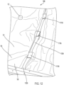
- a diagram 1200 of attaching the blanket tabs to an inner mold line of a frame structure of an aircraft is illustrated, according to an exemplary embodiment.
- the hook tape 1120A is aligned along the inner mold line 1102A.
- the first group of blanket tabs 1110A is attached to the hook tape 1120A to secure the insulation blanket assembly 100 to the inner mold line 1102A.
- FIG. 13 a diagram 1300 of attaching a first blanket tab of a first insulation blanket assembly to a second blanket tab of a second insulation blanket assembly, according to an exemplary embodiment.
- the aircraft structures 1302 can correspond to supports for aircraft flooring, such as the floor 204.
- the diagram 1300 also includes an insulation blanket assembly 100C and an insulation blanket assembly 100D.
- Each insulation blanket assembly 110C, 110D can correspond to the insulation blanket assembly 100A or the insulation blanket assembly 100B.
- the insulation blanket assemblies 100C, 100D are placed under the aircraft structures 1302 to provide thermal and acoustic insulation to an aircraft.
- tape 1310 e.g., hook tape and/or loop tape
- tape 1320 e.g., double-sided hook tape and/or loop tape
- FIG. 14 a cross-sectional diagram 1400 of an installation blanket assembly installed on an aircraft is illustrated, according to an exemplary embodiment.
- the stringer 250 is coupled to the inner mold line 1102 of a frame structure, such as one of the frame structures 304 of Figure 3 .
- Portions of the insulation blanket assembly 100 are also depicted in Figure 14 .
- the insulation material 110 and the outboard material 102 are depicted in Figure 14 .
- the support rails 106 are attached to the insulation material 110 to provide separation between the stringers 250 and the insulation material 110, which reduces or eliminates moisture from transferring to the insulation material 110.
- the hook tape 1120 is aligned along the mold line 1102.
- the blanket tab 1110 is attached to the hook tape 1120 via loop tape 1402.
- the loop tape 1402 e.g., double-sided tape
- the loop tape 1402 is placed on the hook tape 1120 to provide additional adhesive security when installing the insulation blanket assembly 100.
- FIG. 15 another cross-sectional diagram 1500 of an installation blanket assembly installed on an aircraft is illustrated, according to an exemplary embodiment.
- the stringer 250 is coupled to the inner mold line 1102 of the frame structure, such as one of the frame structures 304 of Figure 3 .
- Portions of the insulation blanket assembly 100 are also depicted in Figure 15 .
- the insulation material 110 and the outboard material 102 are depicted in Figure 15 .
- the support rails 106 are attached to the outboard material 102 to provide separation between the stringers 250 and the insulation material 110, which reduces or eliminates moisture from transferring to the insulation material 110.
- the hook tape 1120 is aligned along the mold line 1102.
- the blanket tab 1110 is attached to the hook tape 1120 via loop tape 1402.
- the loop tape 1402 e.g., double-sided tape
- the loop tape 1402 is placed on the hook tape 1120 to provide additional adhesive security when installing the insulation blanket assembly 100.
- Figure 16 illustrates a flow chart of a method 1600, according to an exemplary embodiment.
- the method 1600 includes providing an insulation material, at block 1602.
- the method 1600 also includes forming a cover, at block 1604.
- the method 1600 also includes, prior to or after forming the cover, attaching one or more support rails to at least one of the cover or the insulation material such that, when installed on the aircraft, the one or more support rails provide separation of the insulation material from an outer panel of the aircraft for moisture management, at block 1606.
- forming the cover includes attaching an inboard material to an outboard material such that the insulation material is between the inboard material and the outboard material.
- attaching the one or more support rails includes attaching the one or more support rails to the insulation material such that the one or more support rails are positioned between the outboard material and the insulation material.
- attaching the one or more support rails includes attaching the one or more support rails to the outboard material such that the outboard material is between the insulation material and the one or more support rails.
- the method 1600 may include, prior to attaching the one or more support rails, forming a beveled edge on opposing endos of an elongated member.
- the elongated member may correspond to at least one support rail of the one or more support rails.
- attaching the one or more support rails includes (i) attaching a first support rail of the one or more support rails to at least one of the cover or the insulation material and (ii) attaching a second support rail of the one or more support rails to at least one of the cover of the insulation material.
- the first support rail and the second support rail may have a parallel orientation.
- Figure 17 illustrates a flow chart of a method 1700, according to an exemplary embodiment.
- the method 1700 includes applying (i) first hook tape to a first inner mold line of a first aircraft frame structure and (ii) second hook tape to a second inner mold line of a second aircraft frame structure, at block 1702.
- the first hook tape and the second hook tape are double-sided tapes.
- the method 1700 also includes applying (i) first loop tape to a first group of blanket tabs attached to a first edge of an outboard material of an insulation blanket assembly and (ii) second loop tape to a second group of blanket tabs attached to a second edge of the outboard material, at block 1704.
- the first loop tape and the second loop tape are double-sided tapes, and the insulation blanket assembly includes one or more support rails that extend transverse relative to aircraft stringers.
- the method 1700 also includes attaching (i) the first group of blanket tabs to the first inner mold line by placing the first loop tape on top of the first hook tape and (ii) the second group of blanket tabs to the second inner mold line by placing the second loop tape on top of the second hook tape, at block 1706.
- the techniques described with respect to Figures 1-17 reduce the likelihood or risk of an insulation blanket blocking water on its way down drain paths by attaching support rails into the insulation blanket to elevate the insulation blanket (e.g., prevent the insulation blanket from laying flush against skin and structure in the lower lobe structure of the aircraft).
- the foam support rails allow water drainage above and below the surface of the insulation blanket. Additionally, the increased gap between the insulation blanket and the lower lobe structure of the aircraft can prevent insulation materials within the insulation blanket from becoming saturated with moisture, thus increasing the in-service performance of the insulation blanket.
- system can be a vehicle other than a spacecraft without departing from the essence of the present disclosure.
- instances in this specification where one element is "coupled" to another element can include direct and indirect coupling.
- Direct coupling can be defined as one element coupled to and in some contact with another element.
- Indirect coupling can be defined as coupling between two elements not in direct contact with each other, but having one or more additional elements between the coupled elements.
- securing one element to another element can include direct securing and indirect securing.
- adjacent does not necessarily denote contact. For example, one element can be adjacent another element without being in contact with that element.
- a system, apparatus, structure, article, element, component, or hardware “configured to” perform a specified function is indeed capable of performing the specified function without any alteration, rather than merely having potential to perform the specified function after further modification.
- the system, apparatus, structure, article, element, component, or hardware “configured to” perform a specified function is specifically selected, created, implemented, utilized, programmed, and/or designed for the purpose of performing the specified function.
- "configured to” denotes existing characteristics of a system, apparatus, structure, article, element, component, or hardware which enable the system, apparatus, structure, article, element, component, or hardware to perform the specified function without further modification.
- a system, apparatus, structure, article, element, component, or hardware described as being “configured to” perform a particular function may additionally or alternatively be described as being “adapted to” and/or as being “operative to” perform that function.
- first, second, etc. are used herein merely as labels, and are not intended to impose ordinal, positional, or hierarchical requirements on the items to which these terms refer. Moreover, reference to, e.g., a “second” item does not require or preclude the existence of, e.g., a "first” or lower-numbered item, and/or, e.g., a "third" or higher-numbered item.
Landscapes
- Engineering & Computer Science (AREA)
- Aviation & Aerospace Engineering (AREA)
- Mechanical Engineering (AREA)
- Manufacturing & Machinery (AREA)
- Transportation (AREA)
- Laminated Bodies (AREA)
Abstract

Description
- The present application claims priority from
U.S. Provisional Patent Application No. 63/533,610, entitled "Support Rails for Insulation Blanket", filed August 18, 2023 - The present disclosure generally relates to insulation, and more particularly, to support rails for aircraft insulation blankets.
- This background description is provided for the purpose of generally presenting the context of the disclosure. Unless otherwise indicated herein, material described in this section is neither expressly nor impliedly admitted to be prior art to the present disclosure or the appended claims.
- Aircrafts use thermal and acoustic insulation for different purposes. For example, thermal and acoustic insulation can be used to reduce noise transfer and thermal conduction with outside elements of an aircraft. Additionally, thermal and acoustic insulation can be used to channel moisture generated in an upper lobe cabin of the aircraft down to drains in a lower lobe structure of the aircraft, where the moisture exits the aircraft. However, thermal and acoustic insulation can become saturated from the moisture and can block water on its way along a drain path.
- The present application is directed to reducing a rate at which an insulation blanket becomes saturated on an aircraft. In particular, according to the present application, one or more support rails are attached to, or embedded within, the insulation blanket to provide separation between an insulation material of the insulation blanket and an aircraft structure, such as a fuselage panel, to reduce or eliminate moisture associated with the aircraft structure from saturating the insulation material.
- Moisture generated in an upper lobe of the aircraft is typically channeled down to drains in a lower lobe structure of the aircraft, from which the moisture exits the aircraft. Thus, moisture typically collects near a lower lobe cheek and bilge of the aircraft before exiting the aircraft. As a result, the lower lobe cheek and bilge of the aircraft can be a relatively wet environment. Along with reducing noise transfer with a surrounding environment of the aircraft, reducing thermal conduction with the surrounding environment of the aircraft, and acting as a barrier against other external hazards, the insulation blanket can be used to channel moisture from the upper lobe of the aircraft down to the drains in the lower lobe structure of the aircraft.
- To reduce the likelihood or risk of the insulation blanket blocking water on its way down drain paths, one or more support rails are attached to, or embedded within, the insulation blanket to provide separation between the insulation material and different aircraft structures (e.g., to prevent the insulation material from laying flush against skin and structure in the lower lobe structure of the aircraft). The one or more support rails can be made of a foam material. The foam support rails allow water drainage above and below the surface of the insulation blanket. In particular, the one or more support rails may be comprised of a closed cell foam to reduce or eliminate moisture absorption. Additionally, the increased gap between the insulation material and the lower lobe structure of the aircraft can prevent the insulation material within the insulation blanket from becoming saturated with moisture, thus increasing the in-service performance of the insulation blanket.
- In one aspect, the present application discloses an insulation blanket assembly for use on an aircraft includes a cover. The cover has an inboard material and an outboard material. The insulation blanket assembly also includes an insulation material between the inboard material and the outboard material. The insulation blanket assembly also includes one or more support rails attached to at least one of the cover or the insulation material. When the insulation blanket assembly is attached to the aircraft, the one or more support rails are configured to provide separation between an aircraft structure and the insulation material to reduce or eliminate moisture from transferring to the insulation material.
- In another aspect, the present application discloses an aircraft. The aircraft includes a fuselage. The fuselage includes a plurality of frame structures and a plurality of stringers attached to the plurality of frame structures. The plurality of stringers extend laterally along a length of the fuselage. The aircraft also includes an insulation blanket assembly attached to at least one frame structure of the plurality of frame structures or to at least one stringer of the plurality of stringers. The insulation blanket assembly includes one or more support rails that extend transverse relative to the plurality of stringers.
- In another aspect, the present application discloses a method of making an insulation blanket assembly for an aircraft. The method includes providing an insulation material. The method also includes forming a cover. The method also includes, prior to or after forming the cover, attaching one or more support rails to at least one of the cover or the insulation material such that, when installed on the aircraft, the one or more support rails provide separation of the insulation material from an outer panel of the aircraft for moisture management.
- In another aspect, the present application discloses a method of installing an insulation blanket assembly on an aircraft. The method includes applying (i) first hook tape to a first inner mold line of a first aircraft frame structure and (ii) second hook tape to a second inner mold line of a second aircraft frame structure. The first hook tape and the first hook tape are double-sided tapes. The method also includes applying (i) first loop tape to a first group of blanket tabs attached to a first edge of an outboard material of an insulation blanket assembly and (ii) second loop tape to a second group of blanket tables attached to a second edge of the outboard material. The first loop tape and the second loop tape are double-sided tapes, and the insulation blanket assembly comprises one or more support rails that extend transverse relative to aircraft stringers. The method also includes attaching (i) the first group of blanket tabs to the first inner mold line by placing the first loop tape on top of the first hook tape and (ii) the second group of blanket tabs to the second inner mold line by placing the second loop tape on top of the second hook tape.
- The foregoing summary is illustrative only and is not intended to be in any way limiting. In addition to the illustrative aspects, embodiments, and features described above, further aspects, embodiments, and features will become apparent by reference to the figures and the following detailed description.
- A more complete understanding of embodiments of the present application may be derived by referring to the detailed description and claims when considered in conjunction with the following figures, wherein like reference numbers may refer to similar elements throughout the figures. The figures are provided to facilitate understanding of the disclosure without limiting the breadth, scope, scale, or applicability of the disclosure. The drawings are not necessarily made to scale.
-
Figure 1A illustrates a diagram of an insulation blanket assembly that includes one or more support rails, according to an exemplary embodiment; -
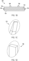
Figure 1B illustrates a cross-sectional diagram of an insulation blanket assembly that includes one or more support rails, according to an exemplary embodiment; -
Figure 1C illustrates a support rail that includes a beveled edge, according to an exemplary embodiment; -
Figure 1D illustrates a support rail that includes a straight edge, according to an exemplary embodiment; -
Figure 1E illustrates another diagram of an insulation blanket assembly that includes one or more support rails, according to an exemplary embodiment; -
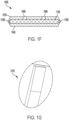
Figure 1F illustrates a cross-sectional diagram of an insulation blanket assembly that includes one or more support rails, according to an exemplary embodiment; -
Figure 1G illustrates a support rail that includes a beveled edge, according to an exemplary embodiment; -
Figure 2 illustrates a cross-sectional, schematic view of an aircraft that includes an insulation blanket assembly, according to an exemplary embodiment; -
Figure 3 illustrates a structural view of an aircraft fuselage that includes the insulation blanket assembly, according to an exemplary embodiment; -
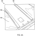
Figure 4A illustrates an insulation blanket assembly that includes one or more support rails attached to an outboard material, according to an exemplary embodiment; -
Figure 4B illustrates an insulation blanket assembly that includes one or more support rails attached to an insulation material, according to an exemplary embodiment; -
Figure 5 illustrates a diagram of one or more support rails attached to an insulation blanket, according to an exemplary embodiment; -
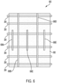
Figure 6 illustrates another diagram of one or more support rails attached to an insulation blanket, according to an exemplary embodiment; -
Figure 7 illustrates another diagram of one or more support rails attached to an insulation blanket, according to an exemplary embodiment; -
Figure 8A illustrates a cross-sectional diagram of portions of an insulation blanket that includes a support rail having a beveled cut, according to an exemplary embodiment; -
Figure 8B illustrates a diagram of a portion of a support rail with a beveled cut, according to an exemplary embodiment; -
Figure 9A illustrates a cross-sectional diagram of portions of an insulation blanket that includes a support rail having a straight edge, according to an exemplary embodiment; -
Figure 9B illustrates a diagram of a portion of a support rail with a straight edge, according to an exemplary embodiment; -
Figure 10A illustrates a cross-sectional diagram of portions of an insulation blanket that includes a support rail having a beveled cut, according to an exemplary embodiment; -
Figure 10B illustrates a diagram of a portion of a support rail with a beveled cut, according to an exemplary embodiment; -
Figure 11 illustrates a diagram of an insulation blanket assembly installed on an aircraft, according to an exemplary embodiment; -
Figure 12 illustrate a diagram of attaching blanket tabs to an inner mold line of a frame structure of an aircraft, according to an exemplary embodiment; -
Figure 13 illustrates a diagram of attaching a first blanket tab of a first insulation blanket assembly to a second blanket tab of a second insulation blanket assembly, according to an exemplary embodiment; -
Figure 14 illustrates a cross-sectional diagram of an installation blanket assembly installed on an aircraft, according to an exemplary embodiment; -
Figure 15 illustrates another cross-sectional diagram of an installation blanket assembly installed on an aircraft, according to an exemplary embodiment; -
Figure 16 is a flowchart of an example of an implementation of a method, according to an exemplary embodiment; and -
Figure 17 is a flowchart of another example of an implementation of a method, according to an exemplary embodiment. - The figures and the following description illustrate specific exemplary embodiments. It will be appreciated that those skilled in the art will be able to devise various arrangements that, although not explicitly described or shown herein, embody the principles described herein and are included within the scope of the claims that follow this description. Furthermore, any examples described herein are intended to aid in understanding the principles of the disclosure and are to be construed as being without limitation. As a result, this disclosure is not limited to the specific embodiments or examples described below, but by the claims and their equivalents.
- Particular implementations are described herein with reference to the drawings. In the description, common features may be designated by common reference numbers throughout the drawings. In some drawings, multiple instances of a particular type of feature are used. Although these features are physically and/or logically distinct, the same reference number is used for each, and the different instances are distinguished by addition of a letter to the reference number. When the features as a group or a type are referred to herein (e.g., when no particular one of the features is being referenced), the reference number is used without a distinguishing letter. However, when one particular feature of multiple features of the same type is referred to herein, the reference number is used with the distinguishing letter. For example, referring to
Figures 1A and1E , insulation blanket assemblies are illustrated and associated withreference number 100. When referring to a particular one of the insulation blanket assemblies, such as theinsulation blanket assembly 100A, the distinguishing letter "A" is used. However, when referring to any arbitrary one of the insulation blanket assemblies or to the insulation blanket assemblies as a group, thereference number 100 may be used without a distinguishing letter. - As used herein, various terminology is used for the purpose of describing particular implementations only and is not intended to be limiting. For example, the singular forms "a," "an," and "the" are intended to include the plural forms as well, unless the context clearly indicates otherwise. Further, the terms "comprise," "comprises," and "comprising" are used interchangeably with "include," "includes," or "including." Additionally, the term "wherein" is used interchangeably with the term "where." As used herein, "exemplary" indicates an example, an implementation, and/or an aspect, and should not be construed as limiting or as indicating a preference or a preferred implementation. As used herein, an ordinal term (e.g., "first," "second," "third," etc.) used to modify an element, such as a structure, a component, an operation, etc., does not by itself indicate any priority or order of the element with respect to another element, but rather merely distinguishes the element from another element having a same name (but for use of the ordinal term). As used herein, the term "set" refers to a grouping of one or more elements, and the term "plurality" refers to multiple elements.
- Referring to
Figure 1A , a diagram of aninsulation blanket assembly 100A that includes one or more support rails is illustrated, according to an exemplary embodiment. According to some implementations, as described in greater detail with respect toFigure 2 , theinsulation blanket assembly 100A can be installed on anaircraft 200. - The
insulation blanket assembly 100A includes acover 101A having anoutboard material 102A and aninboard material 104A. Theinsulation blanket assembly 100A also includes aninsulation material 110A between theinboard material 104A and theoutboard material 102A. For example, referring to the cross-sectional view of theinsulation blanket assembly 100A inFigure 1B , to seal in theinsulation material 110A, theoutboard material 102A of thecover 101A is wrapped around a first side of theinsulation material 110A, and theinboard material 104A of thecover 101A is wrapped around a second side of theinsulation material 110A. An edge of theinboard material 104A is attached to an edge of theoutboard material 102A viatape 103A. - As depicted in
Figures 1A and1B , theinsulation blanket assembly 100A also includes one ormore support rails 106A attached to thecover 101A. In particular, the one ormore support rails 106A are attached to theoutboard material 102A of thecover 101A such that theoutboard material 102A is between theinsulation material 110A and the one or more support rails 106A. The one or more support rails 106A may be attached with double-sided tape or a garment tags. As described below, when theinsulation blanket assembly 110A is attached to an aircraft, such as theaircraft 200 ofFigure 2 , the one ormore support rails 106A are configured to provide separation between an aircraft structure (e.g., such as an aircraft stringer or an aircraft fuselage structure) and theinsulation material 110A to reduce or eliminate moisture from transferring to theinsulation material 110A. - As depicted in
Figure 1A , eachsupport rail 106A of the one or more support rails 106A may include an elongated member that has a length that is less than a length of thecover 101A such that ends of the one or more support rails 106A are separated laterally from a perimeter of thecover 101A. InFigure 1A , theinsulation blanket assembly 100A includes two (2) support rails 106A that extend in a parallel direction relative to each other. However, in other implementations, theinsulation blanket assembly 100A can include additional (or fewer) support rails 106A. As a non-limiting example, in one implementation, theinsulation blanket assembly 100A can include five (5) support rails 106A extended in a parallel direction relative to each other. The support rails 106A may be comprised of a flexible material to enable the support rails 106A to be flexible. As a non-limiting example, the support rails 106A may be comprised of a foam material. - According to one implementation, a
first support rail 106A of the one ormore support rails 106A has a first length, and asecond support rail 106A of the one ormore support rails 106A has a second length that is less than the first length to provide variable rigidity along theinsulation blanket assembly 100A. According to one implementation, afirst support rail 106A of the one or more support rails 106 has a first width, and asecond support rail 106A of the one ormore support rails 106A has a second width that is less than the first width. The first and second support rails 106A may be comprised of the same foam material such that thefirst support rail 106A has a different stiffness than thesecond support rail 106A to provide rigidity to theinsulation blanket assembly 100A. - The
insulation blanket assembly 100 may also include a plurality ofattachment portions 172. Eachattachment portion 172 includes a hole that extends through thecover 101A and theinsulation material 110A to facilitate attachment of theinsulation blanket assembly 100A to an aircraft structure with a fastener. - As depicted in
Figures 1A and1C , at least onesupport rail 106A of the one ormore support rails 106A is an elongated member that includes abeveled edge 107A on opposing ends of the elongated member to facilitate sliding theinsulation blanket assembly 110A into position prior to securing theinsulation blanket assembly 110A to an aircraft structure. As depicted inFigures 1A and1D , at least onesupport rail 106A of the one ormore support rails 106A is an elongated member that includes astraight edge 108A. AlthoughFigure 1A illustrates onesupport rail 106A having thebeveled edge 107A and onesupport rail 106A having thestraight edge 108A, in other implementations, the edges of the support rails 106A can be consistent for theinsulation blanket assembly 100A. For example, eachsupport rail 106A can have thebeveled edge 107A or eachsupport rail 106A can have thestraight edge 108A. - Referring to
Figure 1E , another diagram of aninsulation blanket assembly 100B that includes one or more support rails is illustrated, according to an exemplary embodiment. According to some implementations, as described in greater detail with respect toFigure 2 , theinsulation blanket assembly 100B can be installed on theaircraft 200. - The
insulation blanket assembly 100B includes acover 101B having anoutboard material 102B and aninboard material 104B. Theinsulation blanket assembly 100B also includes aninsulation material 110B between theinboard material 104B and theoutboard material 102B. For example, referring to the cross-sectional view of theinsulation blanket assembly 100B inFigure 1F , to seal in theinsulation material 110B, theoutboard material 102B of thecover 101B is wrapped around a first side of theinsulation material 110B, and theinboard material 104B of thecover 101B is wrapped around a second side of theinsulation material 110B. An edge of theinboard material 104B is attached to an edge of theoutboard material 102B viatape 103B. - As depicted in
Figures 1E and1F , the insulation blanket assembly 100F also includes one or more support rails 106B attached to theinsulation material 110B. In particular, the one or more support rails 106B are attached to theinsulation material 110B such that the one or more support rails 106B are positioned between theoutboard material 102B and theinsulation material 110B. The one or more support rails 106B may be attached with double-sided tape. As described below, when theinsulation blanket assembly 110B is attached to an aircraft, such as theaircraft 200 ofFigure 2 , the one or more support rails 106B are configured to provide separation between an aircraft structure (e.g., such as an aircraft stringer or an aircraft fuselage structure) and theinsulation material 110B to reduce or eliminate moisture from transferring to theinsulation material 110B. - As depicted in
Figure 1E , eachsupport rail 106B of the one or more support rails 106B may include an elongated member that has a length that is less than a length of thecover 101B such that ends of the one or more support rails 106B are separated laterally from a perimeter of thecover 101B. InFigure 1E , theinsulation blanket assembly 100B includes two (2) support rails 106B that extend in a parallel direction relative to each other. However, in other implementations, theinsulation blanket assembly 100B can include additional (or fewer) support rails 106B. As a non-limiting example, in one implementation, theinsulation blanket assembly 100B can include five (5) support rails 106B extended in a parallel direction relative to each other. The support rails 106B may be comprised of a flexible material to enable the support rails 106B to be flexible. As a non-limiting example, the support rails 106B may be comprised of a foam material. - According to one implementation, a
first support rail 106B of the one or more support rails 106B has a first length, and asecond support rail 106B of the one or more support rails 106B has a second length that is less than the first length to provide variable rigidity along theinsulation blanket assembly 100B. According to one implementation, afirst support rail 106B of the one or more support rails 106B has a first width, and asecond support rail 106B of the one or more support rails 106B has a second width that is less than the first width. The first and second support rails 106B may be comprised of the same foam material such that thefirst support rail 106B has a different stiffness than thesecond support rail 106B to provide rigidity to theinsulation blanket assembly 100B. - The
insulation blanket assembly 100B may also include a plurality ofattachment portions 172. Eachattachment portion 172 includes a hole that extends through thecover 101B and theinsulation material 110B to facilitate attachment of theinsulation blanket assembly 100B to an aircraft structure with a fastener. - As depicted in
Figures 1E and1G , at least onesupport rail 106B of the one or more support rails 106B is an elongated member that includes abeveled edge 107B on opposing ends of the elongated member to facilitate sliding theinsulation blanket assembly 110B into position prior to securing theinsulation blanket assembly 110B to an aircraft structure. - Although rectangular support rails 106 are illustrated, different patterns of stiffeners (e.g., support rails) may be utilized according to techniques described herein. Additionally, multiple stiffener cross sections can be utilized according to the techniques described herein. A rectangular stiffener may be used for simplicity; however, a triangle stiffener may add rigidity for higher fabrication costs. In some implementations, multiple rectangular stiffeners may be laminated together in a leaf spring pattern and preloaded with curvature for added stiffness with no additional weight expense.
-
Figure 2 illustrates a cross-sectional, schematic view of anaircraft 200 that includes an insulation blanket assembly, according to an exemplary embodiment. In particular,Figure 2 depicts afuselage 230 of theaircraft 200. - The
fuselage 230 includes afloor 204, aceiling 206, and an aesthetic fascia wall or aninner wall 208 that defines acabin 202, where theceiling 206 and/or theinner wall 208 represents an interior wall of theaircraft 200. Thefloor 204 of thecabin 202 may be supported by a plurality of supportingbeams 260. Theinner wall 208 is a lining that separates a main cabin, cockpit, and/or other areas within theaircraft 200 from thefuselage 230. Theinner wall 208 can be made of plastic, glass-fiber, carbon fiber, glass-reinforced resin, other reinforced polymers, and/or other materials. Theinner wall 208 can be designed to provide thermal and acoustic insulation as well. - Passengers in the
aircraft 200 may congregate inseats 210 of thecabin 202 during flight.Figure 2 illustrates that, inside of the fuselage 230 (e.g., in the cabin 202), respiration and other sources of water cause amoisture 220 to enter or form in the air in thecabin 202. As a non-limiting example, warm exhaled air includes themoisture 220 and rises upward through theceiling 206. Some of the warm air rises into aspace 240 between anouter wall 216 of theaircraft 200 and thecabin 202. - As the
outer wall 216 is cooled by outside air at high altitude during flight, the temperature of theouter wall 216 eventually decreases to a temperature below a freezing temperature of water. This cooling causes the moisture 220 (e.g., water) to condense out of the air in thespace 240 and freeze onto an interior surfaces of theouter wall 216 as ice. As theaircraft 200 changes to a lower altitude and/or commences descent for landing and the temperature increases, the ice begins to melt causing water droplets 225 (e.g., liquid) to travel through thespace 240 towards a bottom of thefuselage 230. - The
space 240 can include one or moreinsulation blanket assemblies 100 to provide thermal and acoustic insulation to theaircraft 200. Theinsulation blanket assemblies 100 inFigure 2 can correspond to theinsulation blanket assembly 100A ofFigure 1A or theinsulation blanket assembly 110B ofFigure 1E . As illustrated inFigure 2 , the support rails 106 of one of theinsulation blanket assemblies 110 are proximate to (e.g., resting on)aircraft stringers 250 running along theouter wall 216 of thefuselage 230. - The one or more support rails 106 may extend perpendicular relative to the
stringers 250 such that the one or more support rails 106 provide a drainage path downwardly towards a lower area of thefuselage 230. For example, the orientation of the support rails 106 is perpendicular to an orientation of theaircraft stringers 250 such that the support rails 106 can rest on theaircraft stringers 250 to provide separation between theinsulation material 110 and an aircraft structure, such as theaircraft stringers 250 and/or theouter wall 216 of thefuselage 230. The support rails 106 of the otherinsulation blanket assembly 100 is resting flush on theouter wall 216 of thefuselage 230 to provide separation between theinsulation material 110 and theouter wall 216. - The support rails 106 reduce an amount of moisture transferred to the
insulation material 110 as the water droplets 225 (e.g., liquid) travel through thespace 240 towards the bottom of thefuselage 230. For example, the separation between theinsulation material 110 and the different aircraft structures caused by the support rails 106 enable theinsulation material 110 to remain relatively dry, which decreases the rate at which theinsulation material 110 becomes saturated and thus improves (e.g., lengthens) the lifespan of theinsulation blanket assembly 100. It should also be appreciated that because the support rails 106 are flexible (e.g., comprised of a foam material), the support rails 106 can take the shape of the aircraft structures on which theinsulation blanket assemblies 100 rest. For example, because the one or more support rails 106 are comprised of a flexible foam material, and because theinsulation material 110 and thecover 101 are flexible, theinsulation blanket assembly 100 may radially conform to a shape of thefuselage 230 of theaircraft 200 when installed. -
Figure 3 illustrates a structural view of theaircraft fuselage 230 that includes theinsulation blanket assembly 100, according to an exemplary embodiment. - The
aircraft fuselage 230 includes thefloor 204 that is supported by the plurality of supportingbeams 260. The supportingbeams 260 can be coupled to (and supported by) a plurality ofstruts 302. Theaircraft stringers 250 run along the side of theaircraft fuselage 230 and are supported by a plurality ofcircular frame structures 304. For example, the plurality ofstringers 250 may be attached to the plurality offrame structures 304 and may extend laterally along a length of thefuselage 230. Theskin 306 of theaircraft 200 is coupled to thecircular frame structures 304 and theaircraft stringers 250. - As illustrated in
Figure 3 , the support rails 106 of theinsulation blanket assembly 100 are positioned perpendicular to the orientation of theaircraft stringers 250. As a result, moisture (e.g., the water droplets 225) can travel downwardly and be collected at the bottom of theaircraft fuselage 230 for discharge. Typically, existing insulation blankets become heavily saturated due to thewater droplets 225; however, the configuration of the support rails 106 on theinsulation blanket assembly 100 enable theinsulation material 110 to be separated from thewater droplets 225 as thedroplets 225 travel downwardly, which also promotes vertical drainage of thewater droplets 225. -
Figure 4A illustrates theinsulation blanket assembly 100A that includes one or more support rails attached to an outboard material, according to an exemplary embodiment. As illustrated inFigure 4A , the support rails 106A are attached to theoutboard material 102A of thecover 101A such that theoutboard material 102A is between the insulation material (not shown inFigure 4A ) and the support rails 106A. -
Figure 4B illustrates an insulation blanket assembly that includes one or more support rails attached to an insulation material, according to an exemplary embodiment. As illustrated inFigure 4B , thesupport rail 106B is attached to theinsulation material 110B via an adhesive 402, such as double-sided tape. Thesupport rail 106B is between theinsulation material 110B and theoutboard material 102B of thecover 101B. - Referring to
Figure 5 , a diagram 500 of one or more support rails attached to an insulation blanket is illustrated, according to an exemplary embodiment - The diagram 500 depicts an
insulation blanket 550 that rests on one ormore aircraft stringers 250. One or more support rails 506A, 506B are positioned to elevate theinsulation blanket 550 with respect to theaircraft stringers 250. For example, inFigure 5 , two (2) support rails 506A, 506B are positioned to elevate theinsulation blanket 550 with respect to theaircraft stringers 250 to reduce the rate at which theinsulation blanket 550 becomes saturated with moisture associated with theaircraft stringers 250 or with aircraft skin. The support rails 506A, 506B can be comprised of a foam material. - Referring to
Figure 6 , a diagram 600 of one or more support rails attached to an insulation blanket is illustrated, according to an exemplary embodiment - The diagram 600 depicts an
insulation blanket 650 that rests on one ormore aircraft stringers 250. One or more support rails 606A, 606B, 606C, 606D, 606E are positioned to elevate theinsulation blanket 650 with respect to theaircraft stringers 250. For example, inFigure 6 , five (5) support rails 606A, 606B, 606C, 606D, 606E are positioned to elevate theinsulation blanket 650 with respect to theaircraft stringers 250 to reduce the rate at which theinsulation blanket 650 becomes saturated with moisture associated with theaircraft stringers 250 or with aircraft skin. InFigure 6 , the support rails 606B, 606D are longer than the support rails 606A, 606C, 606E. Thus, different support rails 606 can have different dimensions, as further illustrated inFigure 7 . The support rails 606A, 606B, 606C, 606D, 606E can be comprised of a foam material. - Referring to
Figure 7 , a diagram 700 of one or more support rails attached to an insulation blanket is illustrated, according to an exemplary embodiment - The diagram 700 depicts an
insulation blanket 750 that rests on one ormore aircraft stringers 250. One or more support rails 706A, 706B, 706C, 706D, 706E are positioned to elevate theinsulation blanket 750 with respect to theaircraft stringers 250. For example, inFigure 7 , five (5) support rails 706A, 706B, 706C, 706D, 706E are positioned to elevate theinsulation blanket 750 with respect to theaircraft stringers 250 to reduce the rate at which theinsulation blanket 750 becomes saturated with moisture associated with theaircraft stringers 250 or with aircraft skin. InFigure 7 , the support rails 706B, 706D are shorter than the support rails 706A, 706C, 706E. Thus, different support rails 706 can have different dimensions. The support rails 706A, 706B, 706C, 706D, 706E can be comprised of a foam material. - Referring to
Figure 8A , a cross-sectional diagram 800 of portions of an insulation blanket that includes a support rail having a beveled cut is illustrated, according to an exemplary embodiment. - The diagram 800 depicts portions of an insulation blanket. For example, the diagram 800 depicts an
inboard region 803 of a cover material, anoutboard region 804 of the cover material, and aninsulation material 802 between theinboard region 803 of the cover material and theoutboard region 804 of the cover material. The diagram 800 also depicts asupport rail 806 attached to theoutboard region 804 of the cover material. In particular, anadhesive side 890 of thesupport rail 806 is attached to theoutboard region 804 of the cover material. - Referring to
Figure 8B , a diagram of a portion of the support rail with a beveled cut is illustrated, according to an exemplary embodiment. Thesupport rail 806 can be comprised of a foam material. Thesupport rail 806 has abeveled cut 892 towards the non-adhesive side to facilitate sliding the insulation blanket into position. - Referring to
Figure 9A , a cross-sectional diagram 900 of portions of an insulation blanket that includes a support rail having a straight edge is illustrated, according to an exemplary embodiment. - The diagram 900 depicts portions of an insulation blanket. For example, the diagram 900 depicts an
inboard region 903 of a cover material, anoutboard region 904 of the cover material, and aninsulation material 902 between theinboard region 903 of the cover material and theoutboard region 904 of the cover material. The diagram 900 also depicts asupport rail 906 attached to theoutboard region 904 of the cover material. In particular, anadhesive side 990 of thesupport rail 906 is attached to theoutboard region 904 of the cover material. - Referring to
Figure 9B , a diagram of a portion of the support rail with a straight edge is illustrated, according to an exemplary embodiment. Thesupport rail 906 can be comprised of a foam material. Thesupport rail 906 has a straight edge 992 (e.g., a straight 90 degrees cut) between theadhesive side 990 and the non-adhesive side. - Referring to
Figure 10A , a cross-sectional diagram 1000 of portions of an insulation blanket that includes a support rail having a beveled cut is illustrated, according to an exemplary embodiment. - The diagram 1000 depicts portions of an insulation blanket. For example, the diagram 1000 depicts an
inboard region 1003 of a cover material, anoutboard region 1004 of the cover material, and aninsulation material 1002 between theinboard region 1003 of the cover material and theoutboard region 1004 of the cover material. The diagram 1000 also depicts support rails 1006A, 1006B between theoutboard region 1004 of the cover material and theinsulation material 1002. In particular, anadhesive side 1090 of thesupport rail 1006A is attached to theoutboard region 1004 of the cover material. The same approach applies to supportrail 1006B, etc. - Referring to
Figure 10B , a diagram of a portion of the support rail with a beveled cut is illustrated, according to an exemplary embodiment. The support rail 1006 can be comprised of a foam material. The support rail 1006 has abeveled cut 1092 towards theadhesive side 1090. The same approach applies to supportrail 1006B, etc. - Referring to
Figure 11 , a diagram of an insulation blanket assembly installed on theaircraft 200 is illustrated, according to an exemplary embodiment. - As illustrated in
Figure 11 , theaircraft 200 may include aninner mold line 1102A and aninner mold line 1102B. Theinner mold line 1102A may be an inner mold line of afirst frame structure 304 depicted inFigure 3 , and theinner mold line 1102B may be an inner mold line of asecond frame structure 304 depicted inFigure 3 .Hook tape 1120A (e.g., double-sided tape) may be aligned along theinner mold line 1102A, andhook tape 1120B may be aligned along theinner mold line 1102B. For example, one side of thehook tape inner mold line hook tape blanket tabs - The
insulation blanket assembly 100 may include (i) a first group ofblanket tabs 1110A attached to a first edge of theoutboard material 102 of thecover 101 and (ii) a second group ofblanket tabs 1110B attached to a second edge of theoutboard material 102 of thecover 101. To install theinstallation blanket assembly 100 to theaircraft 200, the first group ofblanket tabs 1110A may be attached to thehook tape 1120A, and the second group ofblanket tabs 1110B may be attached to thehook tape 1120B. - Referring to
Figure 12 , a diagram 1200 of attaching the blanket tabs to an inner mold line of a frame structure of an aircraft is illustrated, according to an exemplary embodiment. According to the diagram 1200, thehook tape 1120A is aligned along theinner mold line 1102A. The first group ofblanket tabs 1110A is attached to thehook tape 1120A to secure theinsulation blanket assembly 100 to theinner mold line 1102A. - Referring to
Figure 13 , a diagram 1300 of attaching a first blanket tab of a first insulation blanket assembly to a second blanket tab of a second insulation blanket assembly, according to an exemplary embodiment. - In the diagram 1300, a plurality of
aircraft structures 1302 are illustrated. In some implementations, theaircraft structures 1302 can correspond to supports for aircraft flooring, such as thefloor 204. The diagram 1300 also includes aninsulation blanket assembly 100C and aninsulation blanket assembly 100D. Each insulation blanket assembly 110C, 110D can correspond to theinsulation blanket assembly 100A or theinsulation blanket assembly 100B. Theinsulation blanket assemblies aircraft structures 1302 to provide thermal and acoustic insulation to an aircraft. - To install the
installation blanket assemblies insulation blanket assembly 100C can be placed on tape 1320 (e.g., double-sided hook tape and/or loop tape) attached to a blanket tab of theinsulation blanket assembly 100D. - Referring to
Figure 14 , a cross-sectional diagram 1400 of an installation blanket assembly installed on an aircraft is illustrated, according to an exemplary embodiment. - In the diagram 1400, the
stringer 250 is coupled to theinner mold line 1102 of a frame structure, such as one of theframe structures 304 ofFigure 3 . Portions of theinsulation blanket assembly 100 are also depicted inFigure 14 . For example, theinsulation material 110 and theoutboard material 102 are depicted inFigure 14 . The support rails 106 are attached to theinsulation material 110 to provide separation between thestringers 250 and theinsulation material 110, which reduces or eliminates moisture from transferring to theinsulation material 110. - The
hook tape 1120 is aligned along themold line 1102. Theblanket tab 1110 is attached to thehook tape 1120 vialoop tape 1402. For example, the loop tape 1402 (e.g., double-sided tape) may be attached toblanket tab 1110. Theloop tape 1402 is placed on thehook tape 1120 to provide additional adhesive security when installing theinsulation blanket assembly 100. - Referring to
Figure 15 , another cross-sectional diagram 1500 of an installation blanket assembly installed on an aircraft is illustrated, according to an exemplary embodiment. - In the diagram 1500, the
stringer 250 is coupled to theinner mold line 1102 of the frame structure, such as one of theframe structures 304 ofFigure 3 . Portions of theinsulation blanket assembly 100 are also depicted inFigure 15 . For example, theinsulation material 110 and theoutboard material 102 are depicted inFigure 15 . The support rails 106 are attached to theoutboard material 102 to provide separation between thestringers 250 and theinsulation material 110, which reduces or eliminates moisture from transferring to theinsulation material 110. - The
hook tape 1120 is aligned along themold line 1102. Theblanket tab 1110 is attached to thehook tape 1120 vialoop tape 1402. For example, the loop tape 1402 (e.g., double-sided tape) may be attached toblanket tab 1110. Theloop tape 1402 is placed on thehook tape 1120 to provide additional adhesive security when installing theinsulation blanket assembly 100. -
Figure 16 illustrates a flow chart of amethod 1600, according to an exemplary embodiment. - The
method 1600 includes providing an insulation material, atblock 1602. - The
method 1600 also includes forming a cover, atblock 1604. - The
method 1600 also includes, prior to or after forming the cover, attaching one or more support rails to at least one of the cover or the insulation material such that, when installed on the aircraft, the one or more support rails provide separation of the insulation material from an outer panel of the aircraft for moisture management, atblock 1606. - According to one implementation of the
method 1600, forming the cover includes attaching an inboard material to an outboard material such that the insulation material is between the inboard material and the outboard material. - According to one implementation of the
method 1600, attaching the one or more support rails includes attaching the one or more support rails to the insulation material such that the one or more support rails are positioned between the outboard material and the insulation material. - According to one implementation of the
method 1600, attaching the one or more support rails includes attaching the one or more support rails to the outboard material such that the outboard material is between the insulation material and the one or more support rails. - According to one implementation, the
method 1600 may include, prior to attaching the one or more support rails, forming a beveled edge on opposing endos of an elongated member. The elongated member may correspond to at least one support rail of the one or more support rails. - According to one implementation of the
method 1600, attaching the one or more support rails includes (i) attaching a first support rail of the one or more support rails to at least one of the cover or the insulation material and (ii) attaching a second support rail of the one or more support rails to at least one of the cover of the insulation material. The first support rail and the second support rail may have a parallel orientation. -
Figure 17 illustrates a flow chart of amethod 1700, according to an exemplary embodiment. - The
method 1700 includes applying (i) first hook tape to a first inner mold line of a first aircraft frame structure and (ii) second hook tape to a second inner mold line of a second aircraft frame structure, atblock 1702. The first hook tape and the second hook tape are double-sided tapes. - The
method 1700 also includes applying (i) first loop tape to a first group of blanket tabs attached to a first edge of an outboard material of an insulation blanket assembly and (ii) second loop tape to a second group of blanket tabs attached to a second edge of the outboard material, atblock 1704. The first loop tape and the second loop tape are double-sided tapes, and the insulation blanket assembly includes one or more support rails that extend transverse relative to aircraft stringers. - The
method 1700 also includes attaching (i) the first group of blanket tabs to the first inner mold line by placing the first loop tape on top of the first hook tape and (ii) the second group of blanket tabs to the second inner mold line by placing the second loop tape on top of the second hook tape, atblock 1706. - The techniques described with respect to
Figures 1-17 reduce the likelihood or risk of an insulation blanket blocking water on its way down drain paths by attaching support rails into the insulation blanket to elevate the insulation blanket (e.g., prevent the insulation blanket from laying flush against skin and structure in the lower lobe structure of the aircraft). The foam support rails allow water drainage above and below the surface of the insulation blanket. Additionally, the increased gap between the insulation blanket and the lower lobe structure of the aircraft can prevent insulation materials within the insulation blanket from becoming saturated with moisture, thus increasing the in-service performance of the insulation blanket. - Although the systems are described herein with specific reference to space systems or aerospace vehicles, in other embodiments, the system can be a vehicle other than a spacecraft without departing from the essence of the present disclosure.
- Additionally, instances in this specification where one element is "coupled" to another element can include direct and indirect coupling. Direct coupling can be defined as one element coupled to and in some contact with another element. Indirect coupling can be defined as coupling between two elements not in direct contact with each other, but having one or more additional elements between the coupled elements. Further, as used herein, securing one element to another element can include direct securing and indirect securing. Additionally, as used herein, "adjacent" does not necessarily denote contact. For example, one element can be adjacent another element without being in contact with that element.
- As used herein, a system, apparatus, structure, article, element, component, or hardware "configured to" perform a specified function is indeed capable of performing the specified function without any alteration, rather than merely having potential to perform the specified function after further modification. In other words, the system, apparatus, structure, article, element, component, or hardware "configured to" perform a specified function is specifically selected, created, implemented, utilized, programmed, and/or designed for the purpose of performing the specified function. As used herein, "configured to" denotes existing characteristics of a system, apparatus, structure, article, element, component, or hardware which enable the system, apparatus, structure, article, element, component, or hardware to perform the specified function without further modification. For purposes of this disclosure, a system, apparatus, structure, article, element, component, or hardware described as being "configured to" perform a particular function may additionally or alternatively be described as being "adapted to" and/or as being "operative to" perform that function.
- The flow chart diagrams included herein are generally set forth as logical flow chart diagrams. As such, the depicted order and labeled steps are indicative of one embodiment of the presented method. Other steps and methods may be conceived that are equivalent in function, logic, or effect to one or more steps, or portions thereof, of the illustrated method. Additionally, the format and symbols employed are provided to explain the logical steps of the method and are understood not to limit the scope of the method. Although various arrow types and line types may be employed in the flow chart diagrams, they are understood not to limit the scope of the corresponding method. Indeed, some arrows or other connectors may be used to indicate only the logical flow of the method. For instance, an arrow may indicate a waiting or monitoring period of unspecified duration between enumerated steps of the depicted method. Additionally, the order in which a particular method occurs may or may not strictly adhere to the order of the corresponding steps shown.
- Unless otherwise indicated, the terms "first," "second," etc. are used herein merely as labels, and are not intended to impose ordinal, positional, or hierarchical requirements on the items to which these terms refer. Moreover, reference to, e.g., a "second" item does not require or preclude the existence of, e.g., a "first" or lower-numbered item, and/or, e.g., a "third" or higher-numbered item.
- While the systems and methods of operation have been described with reference to certain examples, it will be understood by those skilled in the art that various changes can be made and equivalents can be substituted without departing from the scope of the claims. Therefore, it is intended that the present methods and systems not be limited to the particular examples disclosed, but that the disclosed methods and systems include all embodiments falling within the scope of the appended claims.
Claims (16)
- An insulation blanket assembly (100) for use on an aircraft (200), the insulation blanket assembly (100) comprising:a cover (101) having an inboard material (104) and an outboard material (102);an insulation material (110) between the inboard material (104) and the outboard material (102); andone or more support rails (106) attached to at least one of the cover (101) or the insulation material (110), wherein, when the insulation blanket assembly (100) is attached to the aircraft (200), the one or more support rails (106) are configured to provide separation between an aircraft structure and the insulation material (110) to reduce or eliminate moisture from transferring to the insulation material (110).
- The insulation blanket assembly (100) of claim 1, wherein the one or more support rails (106) are attached to the insulation material (110) such that the one or more support rails (106) are positioned between the outboard material (102) and the insulation material (104).
- The insulation blanket assembly (100) of any one of claims 1 or 2, wherein the one or more support rails (106) are attached to the outboard material (102) such that the outboard material (102) is between the insulation material (110) and the one or more support rails (106).
- The insulation blanket assembly (100) of any one of claims 1 to 3, wherein at least one support rail (106) of the one or more support rails (106) is an elongated member that includes a beveled edge (107) on opposing ends of the elongated member to facilitate sliding the insulation blanket assembly (100) into position prior to securing to the aircraft structure.
- The insulation blanket assembly (100) of any one of claims 1 to 4, wherein the one or more support rails (106) are comprised of a flexible foam material, and wherein the cover (101) and the insulation material (110) are flexible, such that the insulation blanket assembly (100) radially conforms to a shape of a fuselage (230) of the aircraft (200) when installed.
- The insulation blanket assembly (100) of any one of claims 1 to 5, wherein an edge of the outboard material (102) is attached to an edge of the inboard material (104) with tape (103), and wherein the one or more support rails (106) are attached with double-sided tape.
- The insulation blanket assembly (100) of any one claims 1 to 6, further comprising a first support rail (106) of the one or more support rails (106) has a first width, a second support rail (106) of the one or more support rails (106) having a second width that is less than the first width, and wherein the first support rail (106) and the second support rail (106) are comprised of the same foam material such that the first support rail (106) has a different stiffness than the second support rail (106) to provide rigidity to the insulation blanket assembly (100).
- The insulation blanket assembly (100) of any one of claims 1 to 7, further comprising a plurality of attachment portions (172), wherein each attachment portion (172) comprises a hole that extends through the cover (101) and the insulation material (110) to facilitate attachment of the insulation blanket assembly (100) to the aircraft structure with a fastener.
- The insulation blanket assembly (100) of any one of claims 1 to 8, wherein each support rail (106) of the one or more support rails (106) comprise an elongated member that has a length that is less than a length of the cover (101) such that ends of the one or more support rails (106) are separated laterally from a perimeter of the cover (101).
- The insulation blanket assembly (100) of any one of claims 1 to 9, wherein a first support rail (106) of the one or more support rails (101) has a first length, wherein a second support rail (106) of the one or more support rails (106) has a second length that is less than the first length to provide variable rigidity along the insulation blanket assembly (100).
- The insulation blanket assembly (100) of any one of claims 1 to 10, wherein the one or more support rails (106) comprise at least two support rails (106) that extend in a parallel direction relative each other.
- An aircraft (200) comprising:a fuselage (230) comprising a plurality of frame structures (304) and a plurality of stringers (250) attached to the plurality of frame structures (304), the plurality of stringers (250) extending laterally along a length of the fuselage (230); andan insulation blanket assembly (100) according to any one of claims 1 to 11 attached to at least one frame structure (304) of the plurality of frame structures (304) or to at least one stringer (250) of the plurality of stringers (250), wherein the one or more support rails (106) of the insulation blanket assembly (100) extend transverse relative to the plurality of stringers (250).
- The aircraft (200) of claim 12, wherein the one or more support rails (106) extend perpendicular relative to the plurality of stringers (250) such that the one or more support rails (106) provide a drainage path downwardly towards a lower area of the fuselage (230).
- The aircraft (200) of claim 12, wherein first hook tape (1120) is aligned along a first inner mold line (1102) of a first frame structure (304) of the plurality of frame structures (304) and second hook tape (1120) is aligned along a second inner mold line (1102) of a second frame structure (304) of the plurality of frame structures (304), wherein a first group of blanket tabs (1110) attached to a first edge of an outboard material (102) of a cover (101) of the insulation blanket assembly (101) is attached to the first hook tape (1120) via first loop tape (1402), and wherein a second group of blanket tabs (1110) attached to a second edge of the outboard material (102) is attached to the second hook tape (1120) via second loop tape (1402).
- A method (1700) of installing an insulation blanket assembly (100) according to any one of claims 1 to 11 on an aircraft, the method comprising:applying (1702) (i) first hook tape to a first inner mold line of a first aircraft frame structure and (ii) second hook tape to a second inner mold line of a second aircraft frame structure, wherein the first hook tape and the first hook tape are double-sided tapes;applying (1704) (i) first loop tape to a first group of blanket tabs attached to a first edge of the outboard material of the insulation blanket assembly (100) and (ii) second loop tape to a second group of blanket tables attached to a second edge of the outboard material, wherein the first loop tape and the second loop tape are double-sided tapes, and wherein the one or more support rails (106) of the insulation blanket assembly (100) extend transverse relative to aircraft stringers;attaching (1706) (i) the first group of blanket tabs to the first inner mold line by placing the first loop tape on top of the first hook tape and (ii) the second group of blanket tabs to the second inner mold line by placing the second loop tape on top of the second hook tape.
- A method (1600) of making an insulation blanket assembly (100) according to any one of claims 1 to 11 for an aircraft (200), the method (1600) comprising:providing (1602) an insulation material (110);forming (1604) a cover (101); andprior to or after forming the cover (101), attaching (1606) one or more support rails (106) to at least one of the cover (101) or the insulation material (110) such that, when installed on the aircraft (200), the one or more support rails (106) provide separation of the insulation material (110) from an outer panel of the aircraft (200) for moisture management.
Applications Claiming Priority (2)
| Application Number | Priority Date | Filing Date | Title |
|---|---|---|---|
| US202363533610P | 2023-08-18 | 2023-08-18 | |
| US18/658,555 US20250058867A1 (en) | 2023-08-18 | 2024-05-08 | Insulation Blanket Assemblies and Methods |
Publications (1)
| Publication Number | Publication Date |
|---|---|
| EP4509400A1 true EP4509400A1 (en) | 2025-02-19 |
Family
ID=92208805
Family Applications (1)
| Application Number | Title | Priority Date | Filing Date |
|---|---|---|---|
| EP24192211.1A Pending EP4509400A1 (en) | 2023-08-18 | 2024-07-31 | Insulation blanket assemblies and methods |
Country Status (4)
| Country | Link |
|---|---|
| US (1) | US20250058867A1 (en) |
| EP (1) | EP4509400A1 (en) |
| JP (1) | JP2025028821A (en) |
| CN (1) | CN119489921A (en) |
Citations (5)
| Publication number | Priority date | Publication date | Assignee | Title |
|---|---|---|---|---|
| US5435679A (en) * | 1993-07-14 | 1995-07-25 | The Boeing Company | Piercing grommet having detachable tool for installation |
| US5811167A (en) * | 1996-01-25 | 1998-09-22 | W. L. Gore & Associates, Inc. | Packaged insulation and method of making same |
| US20110024561A1 (en) * | 2006-08-22 | 2011-02-03 | Airbus Deutschland Gmbh | Frame element, aircraft air-conditioning system and method for the installation of a frame element in an aircraft |
| US9352821B2 (en) * | 2014-02-11 | 2016-05-31 | The Boeing Company | Retaining device for insulation in an aircraft |
| US10633075B2 (en) * | 2016-12-22 | 2020-04-28 | Airbus Operations Sas | Thermoacoustic insulation module for an aircraft, comprising a mat and a load-bearing structure, and thermoacoustic insulation method for insulating an aircraft by means of such a module |
Family Cites Families (17)
| Publication number | Priority date | Publication date | Assignee | Title |
|---|---|---|---|---|
| US4712349A (en) * | 1984-12-24 | 1987-12-15 | The Dow Chemical Company | Protected membrane roof system for high traffic roof areas |
| US6260660B1 (en) * | 1998-12-18 | 2001-07-17 | Sikorsky Aircraft Corporation | Aircraft cabin interior noise treatment |
| US6358591B1 (en) * | 1999-06-04 | 2002-03-19 | Orcon Corporation | Fire-blocking insulation blanket |
| US7083147B2 (en) * | 2004-03-11 | 2006-08-01 | The Boeing Company | Modularized insulation, systems, apparatus, and methods |
| US7040575B2 (en) * | 2004-03-29 | 2006-05-09 | The Boeing Company | Foam composite insulation for aircraft |
| DE102008062703A1 (en) * | 2008-12-17 | 2010-07-01 | Airbus Deutschland Gmbh | Aircraft cabin panel for sound absorption |
| DE102010052671B4 (en) * | 2010-11-26 | 2017-03-23 | Airbus Operations Gmbh | Insulation arrangement with ventilation openings for aircraft |
| US8662448B2 (en) * | 2011-06-06 | 2014-03-04 | The Boeing Company | System and method for insulating frame member |
| US8770343B2 (en) * | 2011-11-23 | 2014-07-08 | The Boeing Company | Noise reduction system for composite structures |
| EP3242763A4 (en) * | 2015-01-05 | 2018-08-29 | Sikorsky Aircraft Corporation | Integrated vibration damper for additively manufactured structure and method |
| US10875624B2 (en) * | 2016-01-17 | 2020-12-29 | Toyota Tsusho America, Inc. | Carbon flocked tape |
| FR3061129B1 (en) * | 2016-12-22 | 2019-05-31 | Airbus Operations | METHOD FOR MANUFACTURING A THERMOPHONIC ISOLATION MODULE FOR AIRCRAFT COMPRISING A BENDING STEP |
| US10814954B2 (en) * | 2017-01-17 | 2020-10-27 | The Boeing Company | Insulation system |
| US11858614B2 (en) * | 2018-03-02 | 2024-01-02 | The Boeing Company | Aircraft thermal acoustic insulation blanket |
| US20190367151A1 (en) * | 2018-05-30 | 2019-12-05 | The Boeing Company | Sealable securing systems and methods |
| FR3085128B1 (en) * | 2018-08-22 | 2022-01-07 | Hutchinson | 3D THERMOFORM ELEMENT |
| US12441084B2 (en) * | 2021-10-20 | 2025-10-14 | Unison Industries, Llc | Thermal insulation system |
-
2024
- 2024-05-08 US US18/658,555 patent/US20250058867A1/en active Pending
- 2024-07-31 EP EP24192211.1A patent/EP4509400A1/en active Pending
- 2024-08-06 JP JP2024129578A patent/JP2025028821A/en active Pending
- 2024-08-19 CN CN202411137989.0A patent/CN119489921A/en active Pending
Patent Citations (5)
| Publication number | Priority date | Publication date | Assignee | Title |
|---|---|---|---|---|
| US5435679A (en) * | 1993-07-14 | 1995-07-25 | The Boeing Company | Piercing grommet having detachable tool for installation |
| US5811167A (en) * | 1996-01-25 | 1998-09-22 | W. L. Gore & Associates, Inc. | Packaged insulation and method of making same |
| US20110024561A1 (en) * | 2006-08-22 | 2011-02-03 | Airbus Deutschland Gmbh | Frame element, aircraft air-conditioning system and method for the installation of a frame element in an aircraft |
| US9352821B2 (en) * | 2014-02-11 | 2016-05-31 | The Boeing Company | Retaining device for insulation in an aircraft |
| US10633075B2 (en) * | 2016-12-22 | 2020-04-28 | Airbus Operations Sas | Thermoacoustic insulation module for an aircraft, comprising a mat and a load-bearing structure, and thermoacoustic insulation method for insulating an aircraft by means of such a module |
Also Published As
| Publication number | Publication date |
|---|---|
| US20250058867A1 (en) | 2025-02-20 |
| JP2025028821A (en) | 2025-03-05 |
| CN119489921A (en) | 2025-02-21 |
Similar Documents
| Publication | Publication Date | Title |
|---|---|---|
| EP3170741B1 (en) | Aircraft bay blankets that provide enhanced drainage features | |
| US7278610B2 (en) | Aircraft wing with electrothermal deicing and/or anti-icing device | |
| CN108327889B (en) | Lay-up assembly, method of using lay-up assembly and insulation layer including lay-up assembly | |
| US10982439B2 (en) | Dry floor liquid disposal system | |
| EP2899127B1 (en) | Dehumidification system for use in a vehicle and method of assembling thereof | |
| WO2007072027A2 (en) | Aircraft fuselage heating | |
| US10023285B2 (en) | Frame insulation providing enhanced drainage features | |
| US10814954B2 (en) | Insulation system | |
| US11091270B2 (en) | Buoyancy driven passive vehicle air drying system and method | |
| US20250058867A1 (en) | Insulation Blanket Assemblies and Methods | |
| US7954760B2 (en) | Cargo floor, system, and method | |
| CA2947185C (en) | Aircraft bay blankets that provide enhanced drainage features | |
| US10442518B2 (en) | Moisture diversion systems and methods of using same | |
| CA2941057C (en) | Enhanced water capture systems for aircraft interiors | |
| EP3653491B1 (en) | Aircraft floor structure | |
| CN111196366A (en) | Nacelle module with integrated drainage device and aircraft with nacelle module | |
| US9352821B2 (en) | Retaining device for insulation in an aircraft | |
| WO2015040376A1 (en) | Ice accretion prevention | |
| EP4186780B1 (en) | Vehicle cabin sidewall-to-floor coupling assembly and method of assembly | |
| BR102019025274B1 (en) | SYSTEM TO PASSIVELY REMOVE MOISTURE, AND, METHOD OF PASSIVE AIR VENTILATION INSIDE A VEHICLE | |
| CN114056544A (en) | Skin structure for a wing, aircraft with a skin structure and method for mounting a skin structure |
Legal Events
| Date | Code | Title | Description |
|---|---|---|---|
| PUAI | Public reference made under article 153(3) epc to a published international application that has entered the european phase |
Free format text: ORIGINAL CODE: 0009012 |
|
| STAA | Information on the status of an ep patent application or granted ep patent |
Free format text: STATUS: THE APPLICATION HAS BEEN PUBLISHED |
|
| AK | Designated contracting states |
Kind code of ref document: A1 Designated state(s): AL AT BE BG CH CY CZ DE DK EE ES FI FR GB GR HR HU IE IS IT LI LT LU LV MC ME MK MT NL NO PL PT RO RS SE SI SK SM TR |
|
| STAA | Information on the status of an ep patent application or granted ep patent |
Free format text: STATUS: REQUEST FOR EXAMINATION WAS MADE |
|
| 17P | Request for examination filed |
Effective date: 20250715 |
|
| GRAP | Despatch of communication of intention to grant a patent |
Free format text: ORIGINAL CODE: EPIDOSNIGR1 |
|
| STAA | Information on the status of an ep patent application or granted ep patent |
Free format text: STATUS: GRANT OF PATENT IS INTENDED |
|
| INTG | Intention to grant announced |
Effective date: 20260129 |