EP4509399A1 - Thresholds for flooring in an aircraft - Google Patents
Thresholds for flooring in an aircraft Download PDFInfo
- Publication number
- EP4509399A1 EP4509399A1 EP24185798.6A EP24185798A EP4509399A1 EP 4509399 A1 EP4509399 A1 EP 4509399A1 EP 24185798 A EP24185798 A EP 24185798A EP 4509399 A1 EP4509399 A1 EP 4509399A1
- Authority
- EP
- European Patent Office
- Prior art keywords
- threshold
- edge
- body portion
- vertical body
- flooring material
- Prior art date
- Legal status (The legal status is an assumption and is not a legal conclusion. Google has not performed a legal analysis and makes no representation as to the accuracy of the status listed.)
- Withdrawn
Links
Images





Classifications
-
- B—PERFORMING OPERATIONS; TRANSPORTING
- B64—AIRCRAFT; AVIATION; COSMONAUTICS
- B64C—AEROPLANES; HELICOPTERS
- B64C1/00—Fuselages; Constructional features common to fuselages, wings, stabilising surfaces or the like
- B64C1/18—Floors
-
- B—PERFORMING OPERATIONS; TRANSPORTING
- B32—LAYERED PRODUCTS
- B32B—LAYERED PRODUCTS, i.e. PRODUCTS BUILT-UP OF STRATA OF FLAT OR NON-FLAT, e.g. CELLULAR OR HONEYCOMB, FORM
- B32B27/00—Layered products comprising a layer of synthetic resin
- B32B27/06—Layered products comprising a layer of synthetic resin as the main or only constituent of a layer, which is next to another layer of the same or of a different material
- B32B27/08—Layered products comprising a layer of synthetic resin as the main or only constituent of a layer, which is next to another layer of the same or of a different material of synthetic resin
-
- B—PERFORMING OPERATIONS; TRANSPORTING
- B32—LAYERED PRODUCTS
- B32B—LAYERED PRODUCTS, i.e. PRODUCTS BUILT-UP OF STRATA OF FLAT OR NON-FLAT, e.g. CELLULAR OR HONEYCOMB, FORM
- B32B27/00—Layered products comprising a layer of synthetic resin
- B32B27/30—Layered products comprising a layer of synthetic resin comprising vinyl (co)polymers; comprising acrylic (co)polymers
- B32B27/304—Layered products comprising a layer of synthetic resin comprising vinyl (co)polymers; comprising acrylic (co)polymers comprising vinyl halide (co)polymers, e.g. PVC, PVDC, PVF, PVDF
-
- B—PERFORMING OPERATIONS; TRANSPORTING
- B32—LAYERED PRODUCTS
- B32B—LAYERED PRODUCTS, i.e. PRODUCTS BUILT-UP OF STRATA OF FLAT OR NON-FLAT, e.g. CELLULAR OR HONEYCOMB, FORM
- B32B27/00—Layered products comprising a layer of synthetic resin
- B32B27/40—Layered products comprising a layer of synthetic resin comprising polyurethanes
-
- B—PERFORMING OPERATIONS; TRANSPORTING
- B32—LAYERED PRODUCTS
- B32B—LAYERED PRODUCTS, i.e. PRODUCTS BUILT-UP OF STRATA OF FLAT OR NON-FLAT, e.g. CELLULAR OR HONEYCOMB, FORM
- B32B3/00—Layered products comprising a layer with external or internal discontinuities or unevennesses, or a layer of non-planar shape; Layered products comprising a layer having particular features of form
- B32B3/02—Layered products comprising a layer with external or internal discontinuities or unevennesses, or a layer of non-planar shape; Layered products comprising a layer having particular features of form characterised by features of form at particular places, e.g. in edge regions
- B32B3/08—Layered products comprising a layer with external or internal discontinuities or unevennesses, or a layer of non-planar shape; Layered products comprising a layer having particular features of form characterised by features of form at particular places, e.g. in edge regions characterised by added members at particular parts
-
- B—PERFORMING OPERATIONS; TRANSPORTING
- B32—LAYERED PRODUCTS
- B32B—LAYERED PRODUCTS, i.e. PRODUCTS BUILT-UP OF STRATA OF FLAT OR NON-FLAT, e.g. CELLULAR OR HONEYCOMB, FORM
- B32B37/00—Methods or apparatus for laminating, e.g. by curing or by ultrasonic bonding
- B32B37/12—Methods or apparatus for laminating, e.g. by curing or by ultrasonic bonding characterised by using adhesives
-
- B—PERFORMING OPERATIONS; TRANSPORTING
- B32—LAYERED PRODUCTS
- B32B—LAYERED PRODUCTS, i.e. PRODUCTS BUILT-UP OF STRATA OF FLAT OR NON-FLAT, e.g. CELLULAR OR HONEYCOMB, FORM
- B32B5/00—Layered products characterised by the non- homogeneity or physical structure, i.e. comprising a fibrous, filamentary, particulate or foam layer; Layered products characterised by having a layer differing constitutionally or physically in different parts
- B32B5/02—Layered products characterised by the non- homogeneity or physical structure, i.e. comprising a fibrous, filamentary, particulate or foam layer; Layered products characterised by having a layer differing constitutionally or physically in different parts characterised by structural features of a fibrous or filamentary layer
-
- B—PERFORMING OPERATIONS; TRANSPORTING
- B64—AIRCRAFT; AVIATION; COSMONAUTICS
- B64F—GROUND OR AIRCRAFT-CARRIER-DECK INSTALLATIONS SPECIALLY ADAPTED FOR USE IN CONNECTION WITH AIRCRAFT; DESIGNING, MANUFACTURING, ASSEMBLING, CLEANING, MAINTAINING OR REPAIRING AIRCRAFT, NOT OTHERWISE PROVIDED FOR; HANDLING, TRANSPORTING, TESTING OR INSPECTING AIRCRAFT COMPONENTS, NOT OTHERWISE PROVIDED FOR
- B64F5/00—Designing, manufacturing, assembling, cleaning, maintaining or repairing aircraft, not otherwise provided for; Handling, transporting, testing or inspecting aircraft components, not otherwise provided for
- B64F5/10—Manufacturing or assembling aircraft, e.g. jigs therefor
-
- B—PERFORMING OPERATIONS; TRANSPORTING
- B32—LAYERED PRODUCTS
- B32B—LAYERED PRODUCTS, i.e. PRODUCTS BUILT-UP OF STRATA OF FLAT OR NON-FLAT, e.g. CELLULAR OR HONEYCOMB, FORM
- B32B2274/00—Thermoplastic elastomer material
-
- B—PERFORMING OPERATIONS; TRANSPORTING
- B32—LAYERED PRODUCTS
- B32B—LAYERED PRODUCTS, i.e. PRODUCTS BUILT-UP OF STRATA OF FLAT OR NON-FLAT, e.g. CELLULAR OR HONEYCOMB, FORM
- B32B2605/00—Vehicles
- B32B2605/003—Interior finishings
-
- B—PERFORMING OPERATIONS; TRANSPORTING
- B32—LAYERED PRODUCTS
- B32B—LAYERED PRODUCTS, i.e. PRODUCTS BUILT-UP OF STRATA OF FLAT OR NON-FLAT, e.g. CELLULAR OR HONEYCOMB, FORM
- B32B2605/00—Vehicles
- B32B2605/18—Aircraft
Definitions
- This disclosure relates generally to thresholds and, more particularly, to thresholds for flooring in an aircraft.
- Aircraft fuselages often have different types of flooring materials in different sections of the fuselage. For example, some sections have non-textile flooring (NTF) such as vinyl or rubber mats while other sections have textile flooring such as carpet. Thresholds are installed between the edges where the two flooring materials meet.
- NTF non-textile flooring
- carpet textile flooring
- An aircraft includes a subfloor, first flooring material on the subfloor, the first flooring material having a first edge, and second flooring material on the subfloor, the second flooring material having a second edge.
- the aircraft includes a threshold at least partially between the first flooring material and the second flooring material.
- the threshold includes a vertical body portion having a top surface, a bottom surface opposite the top surface, a first side surface, and a second side surface opposite the first side surface.
- the vertical body portion has a concave area extending into the second side surface at the bottom surface, wherein the second edge of the second flooring material extends into the concave area.
- the threshold also includes a ramp portion extending from the first side surface.
- the ramp portion has a decreasing thickness from the vertical body portion to a distal end of the ramp portion. The ramp portion is positioned between a portion of the first flooring material and the subfloor.
- a threshold to be installed between two flooring materials includes a vertical body portion having a top surface, a bottom surface opposite the top surface, a first side surface, and a second side surface opposite the first side surface.
- the second side surface has a concave area at the bottom surface to receive an edge of a flooring material.
- the concave area forms an overhang on the second side surface.
- the threshold also includes a ramp portion extending from the first side surface.
- the ramp portion has a decreasing thickness from the vertical body portion to a distal end of the ramp portion.
- a method of installing flooring materials and a threshold in an aircraft includes adhering a first portion of a first flooring material to a subfloor in the aircraft and adhering the threshold to the subfloor near a first edge of the first flooring material.
- the threshold includes a vertical body portion having a top surface, a bottom surface opposite the top surface, a first side surface, and a second side surface opposite the first side surface.
- the vertical body portion has a concave area extending into the second side surface at the bottom surface.
- the threshold also includes a ramp portion extending from the first side surface.
- the ramp portion has a decreasing thickness from the vertical body portion to a distal end of the ramp portion.
- the method also includes adhering a second portion of the first flooring material on top of the ramp portion of the threshold such that the first edge of the first flooring material is adjacent the first side surface of the vertical body portion.
- the method also includes adhering a second flooring material to the subfloor and tucking a second edge of the second flooring material into the concave area of the threshold.
- Thresholds are used to form a smooth transition where the edges of two flooring materials meet. Thresholds are commonly used in aircraft between different flooring sections. For example, the galley of the fuselage often has a mat or plastic flooring, whereas the passenger area of the fuselage has carpet flooring. A threshold can be installed between the edges of the mat and the carpet. The threshold helps to keep the mat and/or the carpet from lifting, as well as provides a smooth transition from one flooring material to the other as they are of different thicknesses
- Known thresholds are relatively bulky and create a noticeable bump between the two flooring materials. This bump can be a nuisance to wheeled-devices such as galley carts, luggage, wheel chairs, knee scooters, etc. Further, known thresholds have long arms that extend over the tops of both flooring materials. These arms form weak points of the threshold that are prone to cracking, chipping, warping, and shrinkage problems.
- Disclosed herein are low profile thresholds that do not create a large bump as seen in known threshold designs. This enables galley carts and other wheeled-devices to easily roll between the two flooring materials without causing a noticeable bump.
- the example thresholds disclosed herein are also less prone to failure, which reduces costs associated with maintenance of the aircraft.
- the example thresholds disclosed herein are lighter and constructed of less material than known thresholds. As such, the example thresholds disclosed herein are less expensive to manufacture.
- the example thresholds disclosed herein can be used for new installations or retrofitted on existing floorings during refreshes (e.g., every 3-6 months).
- An example threshold disclosed herein includes a vertical body portion and a ramp portion.
- the threshold is constructed as a single or unitary part (e.g., a monolithic structure), such as via an extrusion process.
- the threshold is constructed of thermoplastic polyurethane (TPU).
- TPU thermoplastic polyurethane
- the vertical body portion is disposed between the edges of the first and second flooring materials.
- the ramp portion extends from a first side of the vertical body portion and is installed under the first flooring material (e.g., a mat).
- the ramp portion has an increasing thickness to raise the first flooring material up closer to the height of the second flooring material (e.g., carpet).
- the second side surface of the vertical body portion has a concave area (e.g., a cove or recess) that forms a small overhang.
- An edge of the second flooring material is tucked into the concave area.
- the small overhang reduces or limits the amount the edge of the second flooring material can be lifted.
- the overhang is relatively small compared to the arms of known thresholds. This reduces or limits weak points that can lead to cracking.
- the example thresholds disclosed herein are described in connection with floors in an aircraft, the example thresholds disclosed herein can also be used in connection with any floor.
- the thresholds can be used in other types of vehicles (e.g., buses, trains, etc.), in residential buildings, in commercial buildings, and/or any other location where thresholds are commonly used between two flooring materials.
- FIG. 1 illustrates an example aircraft 100 in which the examples disclosed herein can be implemented.
- the aircraft 100 includes a fuselage 102, a first wing 104 (a left wing) coupled to the fuselage 102, a second wing 106 (a right wing) coupled to the fuselage 102, and an empennage 108 at an aft end of the fuselage 102.
- the empennage 108 has a horizontal stabilizer 110 and a vertical stabilizer 112.
- the aircraft 100 also includes a first engine 114 carried by the first wing 104 and a second engine 116 carried by the second wing 106.
- the aircraft 100 may have multiple engines coupled to each of the first and second wings 104, 106 and/or disposed in other locations on the aircraft 100 (e.g., coupled to the fuselage 102, coupled to the empennage 108, etc.).
- the fuselage 102 of the aircraft 100 carries passengers and/or cargo.
- the fuselage 102 may contain one or more floors or levels having flooring.
- the flooring may include carpets and/or mats, for example. Disclosed herein are example thresholds that can be used between the edges or joints where two flooring materials meet.
- FIG. 2 is a cross-sectional or side view of an example threshold 200 that can be used in the example aircraft 100.
- the threshold 200 can be used as a transition between two flooring materials (e.g., a mat and carpet) in the fuselage 102 of the aircraft 100.
- the threshold 200 forms a smooth transition between the flooring materials to reduce (e.g., minimize) bumps as well as damage to the flooring materials.
- the threshold 200 has one or more portions or sections.
- the threshold 200 has a vertical body portion 202 and a ramp portion 204 coupled to and extending from the vertical body portion 202.
- the vertical body portion 202 is disposed between the edges of the two flooring materials, and the ramp portion 204 extends under one of the flooring materials to help raise the flooring material to the same height as the other flooring material.
- the threshold 200 can be constructed to any length (the dimension extending into and out of the page).
- the vertical body portion 202 has a generally rectangular cross-sectional shape.
- the vertical body portion 202 has a top surface 206, a bottom surface 208 opposite the top surface 206, a first side surface 210, and a second side surface 212 opposite the first side surface 210.
- the vertical body portion 202 has a concave area 214 extending into the second side surface 212 at the bottom surface 208.
- the second side surface 212 has or forms the concave area 214 at the bottom surface 208.
- the concave area 214 may also be referred to as a recess or cove.
- the concave area 214 receives an edge of the flooring material, as shown in further detail herein.
- the concave area 214 forms an overhang 215 on the second side surface 212, which extends outward from the top surface 206. The overhang 215 helps prevent the flooring material from lifting, as shown in further detail herein.
- the vertical body portion 202 of the threshold 200 has a first edge 216 between the top surface 206 and the first side surface 210.
- the first edge 216 is curved or rounded.
- the first edge 216 has a constant radius of curvature.
- the threshold 200 also has a second edge 218 between the top surface 206 and the second side surface 212.
- the second edge 218 is curved or rounded.
- the second edge 218 has a constant radius of curvature.
- the first and second edges 216, 218 have a radius of curvature of 0.89 mm (0.035 inches). In other examples, the radius of curvature may be larger or smaller.
- the first and second edges 216, 218 are curved or rounded to provide a smooth transition along the top surface 206 of the threshold 200.
- the top surface 206 of the vertical body portion 202 is curved or rounded (e.g., is convex) between the first edge 216 and the second edge 218.
- This curved or rounded shape helps address any tolerances between the heights of the mat 304 and the carpet 306 depicted in FIG. 3 . As such, this curved or rounded shape helps provide a smooth transition between the flooring materials.
- the top surface 206 has a continuous curvature between the first edge 216 and the second edge 218.
- the top surface 206 is curved at a constant radius of curvature between the first edge 216 and the second edge 218.
- the radius of curvature is 50 mm (2 inches). In other examples, the radius of curvature may be larger or smaller.
- the top surface 206 may be curved at a changing radius of curvature between the first edge 216 and the second edge 218.
- the ramp portion 204 extends from the first side surface 210 of the vertical body portion 202 at the bottom surface 208.
- the ramp portion 204 has a top surface 220, a bottom surface 222 opposite the top surface 220, and a distal end 224.
- the distal end 224 of the ramp portion 204 is rounded or curved.
- the distal end 224 can have sharp corners (e.g., 90° corners).
- the bottom surface 222 of the ramp portion 204 is continuous with the bottom surface 208 of the vertical body portion 202. Therefore, the bottom surface 222 and the bottom surface 208 form a bottom side or surface 226 of the threshold 200.
- the ramp portion 204 has a decreasing thickness (e.g., height) from the vertical body portion 202 (the ride side in FIG. 2 ) to the distal end 224 of the ramp portion 204 (the left side in FIG. 2 ). Said another way, the ramp portion 204 increases in thickness from the distal end 224 to the vertical body portion 202.
- the ramp portion 204 has a first thickness T1 at the distal end 224 and a second thickness T2 at the connection to the vertical body portion 202.
- the thickness T2 is greater than the thickness T1. This increasing thickness raises the flooring material to a height that is closer to the top surface 206 of the threshold 200 and to the other flooring material.
- the threshold 200 is constructed of thermoplastic polyurethane (TPU).
- TPU thermoplastic polyurethane
- the threshold can be constructed of Lubrizol ESTANE° 58244, which is an ether based TPU. This type of material has increased durability and dimensional stability.
- the threshold 200 is constructed of polyvinyl chloride (PVC), such as BMS 8-137.
- the threshold 200 can be constructed of other types of materials.
- the threshold 200 is constructed as a single or monolithic structure.
- the threshold 200 may be manufactured via an extrusion process or molding process.
- the threshold 200 can be constructed of two or more separate portions (e.g., the vertical body portion 202 and the ramp portion 204) that are coupled together (e.g., via a joining process) to form the threshold 200.
- the threshold 200 can be constructed as any length depending on the length of the edges of the flooring materials.
- the threshold 200 has an overall height of H1 between the bottom surface 226 and the top surface 206.
- the first side surface 210 has a height of H2 between the top surface 220 of the ramp portion 204 and the top surface 206 of the vertical body portion 202.
- the bottom surface 226 of the threshold 200 has a width W1.
- the vertical body portion 202 has a width W2.
- the ramp portion 204 increases in thickness from T1 to T2.
- the overhang 215 has a width W3 and a height H3.
- the dimension can be based on the type and/or thicknesses of the flooring materials between which a transition is needed. In some examples, the ratio W1/W2 is greater than 2 or 3.
- the ramp portion 204 is relatively wide (in the horizontal direction) compared to the vertical body portion.
- having a larger width W1 provides a sufficient lower surface for adhesive or double-sided tape widths, while also providing enough material to be tucked under the flooring material (e.g., a mat) to help hold the threshold 200 down, which provides more stability and rigidity to the threshold 200. This also results in a longer, more gradual rise in the height of the flooring material, which reduces (e.g., minimizes) noticeable bumps in the flooring.
- having a smaller width W2 is advantageous for aesthetic purposes, because it reduces (e.g., minimizes) the amount of plastic that is visible (more plastic is generally less aesthetically pleasing).
- FIG. 3 is a cross-sectional view of a portion of a floor 300 in the fuselage 102 ( FIG. 1 ) of the aircraft 100 ( FIG. 1 ) in which the threshold 200 is used.
- the floor 300 includes a subfloor 302 upon which one on more flooring materials are layered.
- the subfloor 302 may be constructed of one or more floor panels of various materials.
- the subfloor 302 is a constructed of a composite material, such as a honeycomb core with graphite or fiberglass plies on the top and bottom.
- the subfloor 302 can be constructed of other materials (e.g., wood, plastic, etc.).
- the floor 300 of the aircraft 100 includes a first flooring material 304 on the subfloor 302 and a second flooring material 306 on the subfloor 302.
- the first flooring material 304 is a mat (e.g., a vinyl mat), referred to herein as the mat 304
- the second flooring material 306 is carpet, referred to herein as the carpet 306.
- the threshold 200 is at least partially disposed between the mat 304 and the carpet 306 and provides a smooth transition between the mat 304 and the carpet 306.
- the mat 304 may be the flooring in the galley of the fuselage 102 ( FIG. 1 ) and the carpet 306 may be the flooring in the passenger seating area of the fuselage 102.
- the threshold 200 provides a smooth transition between these two different flooring materials and areas of the fuselage 102.
- the mat 304 and the carpet 306 have different heights or thicknesses relative to the subfloor 302. Therefore, the threshold 200 also provides a smooth transition between the two different heights.
- the first and second flooring materials 304, 306 can be other types and/or combinations of materials, such as carpet and carpet, mat and mat, carpet and laminate, mat and laminate, etc.
- the threshold 200 is disposed on the subfloor 302.
- the threshold 200 is coupled to the subfloor 302 via an adhesive.
- an adhesive layer 308 is disposed between the bottom surface 226 of the threshold 200 and the subfloor 302.
- the adhesive layer 308 holds the threshold 200 in position on the subfloor 302.
- the adhesive layer 308 is tape, such as a double-sided tape (e.g., BMS 5-133 Type II, Class 2 tape).
- the adhesive layer 308 is a self-adhesive layer on the bottom surface 226 of the threshold 200.
- other types of adhesives can be used (e.g., glue).
- no adhesive layer is used.
- the bottom surface 226 of the threshold 200 can be in direct contact with the subfloor 302 and/or coupled to the subfloor 302 via other mechanisms (e.g., nails, screws, etc.).
- the mat 304 has a top surface 310, a bottom surface 312, and a first edge 314.
- the carpet 306 has a top surface 316, a bottom surface 318, and a second edge 320.
- the thickness of the mat 304 and the carpet 306 are different.
- the mat 304 has a smaller thickness than the carpet 306.
- the threshold 200 is at least partially disposed between the edges 314, 320 of the mat 304 and the carpet 306 and used to create a smooth transition between the two types of flooring and their respective heights.
- a portion of the mat 304 is disposed on or over the ramp portion 204 of the threshold 200.
- the ramp portion 204 is between a portion of the mat 304 and the subfloor 302.
- the weight of the portion of the mat 304 on the ramp portion 204 helps hold the threshold 200 in place.
- the mat 304 may be thinner than the carpet 306. Therefore, the ramp portion 204 provides a gradual increase to the height of the mat 304 so the top surface 310 of the mat 304 is closer to or the same as the height of the top surface 206 of the threshold 200 and the top surface 316 of the carpet 306. This enables wheeled-devices to easily and smoothly roll between the two flooring materials.
- the mat 304 is coupled to the subfloor 302 via an adhesive layer.
- FIG. 3 shows an example adhesive layer 322 on the bottom surface 312 of the mat 304.
- the adhesive layer 322 helps the mat 304 stick to the subfloor 302 to prevent or limit movement.
- the adhesive layer 322 is also between the bottom surface 312 of the mat 304 and the top surface 220 of the ramp portion 204. This helps the threshold 200 remain coupled to the mat 304 and reduces or limits relative movement between the mat 304 and the threshold 200.
- the adhesive layer 322 is a self-adhesive layer that is manufactured with the mat 304, and a liner is provided over the self-adhesive layer. Before installing the mat 304, the liner is removed to expose the self-adhesive layer.
- the adhesive layer 322 can be another type of adhesive, such as a tape (e.g., double-sided tape).
- the first edge 314 of the mat 304 does not extend all the way to the first side surface 210 of the vertical body portion 202 of the threshold 200.
- a sealant 324 is disposed between the first edge 314 of the mat 304 and the first side surface 210 of the vertical body portion 202.
- the sealant 324 may be, for example, BAC5010 TY 60 (RTV108 - Silicone Sealant), BMS5-142, BMS5-45, or another type of sealant.
- the sealant 324 fills the gap or space between the first edge 314 of the mat 304 and the first side surface 210 of the threshold 200 to provide a smooth transition between the top surface 310 of the mat 304 and the top surface 206 of the threshold 200.
- the sealant 324 also prevents liquids from getting underneath the mat 304.
- the second edge 320 of the carpet 306 extends into (e.g., is tucked into) the concave area 214 formed on the second side surface 212 of the threshold 200.
- the second edge 320 of the carpet 306 is in contact with the second side surface 212 of the threshold 200.
- the second edge 320 of the carpet 306 is rounded or curved.
- the second edge 320 of the carpet 306 is edge treated, which helps prevent the carpet 306 from fraying.
- FIGS. 4A and 4B show two example edge treatments for the carpet 306, including serging and speedbinding. In other examples, other types of edge treatments can be implemented. In other examples, such as shown in FIG.
- the carpet 306 is coupled to the subfloor via an adhesive layer 326.
- the carpet 306 is manufactured with a self-adhesive layer or sticky dots on the bottom surface 318 and covered with a liner. Before installing the carpet 306, the liner is removed, and then the carpet 306 can be pressed onto the subfloor 302.
- the second edge 320 of the carpet 306 is disposed in the concave area 214.
- the overhang 215 of the threshold 200 is above (e.g., overhangs) a portion of the carpet 306.
- the overhang 215 limits or prevents the second edge 320 of the carpet 306 from being lifted away from the subfloor 302.
- the design of the concave area 214 and the overhang 215 also reduces (e.g., minimizes) or limits any gaps between the threshold 200 and the carpet 306.
- the overhang 215 is relatively small compared to known thresholds that have long arms that extend over the top of the carpet 306.
- the overhang 215 has a width W3 ( FIG.
- the overhang 215 is about 1/10 th the size of a traditional arm on a threshold. Having a smaller overhang reduces or eliminates weak points for cracking and/or lifting.
- the overhang 215 can have a width W3 that is greater than 2.540 mm (0.100 inches). The width W3 may depend on the type and/or size of flooring material.
- the top surface 206 of the threshold 200 provides a smooth transition between the top surface 310 of the mat 304 and the top surface 316 of the carpet 306.
- the transition is relatively low and does not cause a noticeable bump as seen in known thresholds. This enables wheeled-devices to easily cross over the transition between the mat 304 and the carpet 306. This also reduces impacts and therefore wear and tear on the threshold 200, and thereby improves the life of the threshold 200.
- the various dimensions of the threshold 200 can be selected based on the type and/or size of the flooring materials.
- the threshold 200 is dimensioned to be used with a range of flooring material thicknesses. For example, assume the mat 304 has a minimum thickness of 1.50 mm (0.059 inches (")) and a maximum thickness for 3.35 mm (0.132"), and the carpet 306 has a minimum thickness of 3.55 mm (0.14") and a maximum thickness of 12.0 mm (0.47"). In such an example, referring to FIG.
- the overall height H1 is 4.3 mm (0.17”), the height H2 is 2.8 mm (0.11"), the width W1 is 35.5 mm (1.4"), the width W2 is 10.2 mm (0.40"), the thickness T1 is 1.0 mm (0.04"), the thickness T2 is 1.5 mm (0.06"), the width W3 of the overhang 215 is 25.4 mm (0.100”), and the height H3 of the overhang 215 is 3.12 mm (0.123").
- These dimensions enable the threshold 200 to be used with mats and carpeting having the above-noted ranges of thicknesses, which are commonly found on aircraft. However, in other examples, the threshold 200 can be constructed to have different dimensions.
- the thickness T1 and the height H1 may be larger.
- the height H3 of the overhang 215 may be larger or smaller depending on the thickness of the carpet.
- the height H3 of the overhang 215 may be in the range of 3.12 mm-10.2 mm (0.123"- 0.400").
- the threshold 200 has the overhang 215 on one side and the ramp portion 204 on the opposite side.
- the first side surface 210 of the vertical body portion 202 does not have an overhang or arm that overhangs the mat 304.
- the second side surface 212 does not have a ramp portion that extends below the carpet 306. Therefore, the threshold 200 has an overhang on one side and a ramp portion on the opposite side. This minimal design results in less material and, thus, is lighter and less expensive to manufacture.
- the threshold 200 may have overhangs and/or ramps on both sides.
- FIGS. 5-8 illustrate other example thresholds that may be implemented in the aircraft 100 between the mat 304 and the carpet 306.
- the example thresholds are similar to the threshold 200, except as noted below and shown in the figures. Any of the example aspects (e.g., dimensions, materials, etc.) disclosed in connection with the threshold 200 can likewise apply to the thresholds in FIGS. 5-8 .
- FIG. 5 shows an example threshold 500 having a vertical body portion 502 and a ramp portion 504.
- the vertical body portion 500 has a first surface side 506 and a second side surface 508.
- the first side 506 has an overhang 510. Therefore, when the mat 304 is installed, the overhang 510 is above or overhangs a portion of the mat 304. This limits or prevents the mat 304 from lifting.
- a concave area 512 is formed on the second side surface 508.
- the concave area 512 is larger than the concave area 214 disclosed above. Therefore, the vertical body portion 502 forms a larger arm 514 that overhangs the carpet 306 ( FIG. 3 ).
- FIG. 6 shows an example threshold 600 that has a substantially similar shape as the threshold 200 in FIGS. 2 and 3 .
- the threshold 600 has a channel 602 extending into a bottom surface 604 of a vertical body portion 606.
- the channel 602 helps to keep the thickness of the threshold 600 more constant throughout the extrusion process, which helps to improve extension quality (e.g., minimizes potential flows due to cooling rates and material flows).
- the channel 602 also helps to reduce (e.g., minimize) material usage and weight.
- FIG. 7 shows an example threshold 700 having a vertical body portion 702 and a ramp portion 704.
- the vertical body portion 702 and the ramp portion 704 are similar to the vertical body portion 202 and the ramp portion 204 disclosed above.
- the ramp portion 704 is relatively wide (in the horizontal direction of FIG. 7 ) compared to the width of the vertical body portion 702.
- the vertical body portion 702 is relatively short compared to other vertical body portions. Therefore, the threshold 700 can be advantageous for use with thinner flooring materials. The longer ramp provides a more gradual increase or slope for the flooring material.
- FIG. 8 shows an example threshold 800 having a vertical body portion 802 and a ramp portion 804.
- the threshold 800 is substantially the same as the threshold 700 of FIG. 7 .
- the threshold 800 has a shorter ramp portion.
- the vertical body portion 802 is higher. Therefore, this threshold 800 is advantageous for use with thicker flooring materials.
- FIG. 9 is a flowchart representative of an example method 900 of installing flooring materials and the example threshold 200 in an aircraft, such as the aircraft 100.
- the example method 900 is disclosed in connection with the mat 304 as the first flooring material and the carpet 306 as the second flooring material.
- the example method can be similarly performed in connection with other types of flooring materials.
- the example method 900 can be implemented in connection with other types of thresholds, such as the thresholds of FIGS. 5-8 .
- the method 900 includes positioning the mat 304 in the desired location on the subfloor 302, such as by one or more installer(s). Then, the installer(s) adhere a first portion of the mat 304 to the subfloor 302. For example, the installer(s) can lift back a corner or section of the mat 304 and peel away the liner to expose the adhesive layer 322 (e.g., the self-adhesive layer). The mat 304 can then be laid back on the subfloor 302 to adhere the first portion of the mat 304 to the subfloor 302. All of the mat 304 is adhered to the subfloor 302 except a second portion along the first edge 314.
- the installer(s) adhere a first portion of the mat 304 to the subfloor 302.
- the installer(s) can lift back a corner or section of the mat 304 and peel away the liner to expose the adhesive layer 322 (e.g., the self-adhesive layer).
- the mat 304 can then be laid back on the subfloor 302 to adhere the first
- the liner is kept on the bottom of the mat 304 along the second portion so the mat 304 does not accidently adhere to the subfloor 302.
- the mat 304 may be adhered to the subfloor 302 using a double-sided tape that does not come already installed on the mat 304.
- the method 900 includes positioning the threshold 200 in the desired location along near the first edge 314 of the mat 304.
- the threshold 200 can be adhere to the subfloor 302 with the adhesive layer 308.
- the adhesive layer 308 is double-sided tape. In such an example, the double-side tape can be adhered to the bottom surface 226 of the threshold 200 first, and then the threshold 200 can be adhered to the subfloor 302.
- the adhesive layer 308 may be a self-adhesive layer already on the bottom surface 226 of the threshold 200. Therefore, the method 900 may include positioning the threshold 200, peeling off a liner that covers the self-adhesive layer, and then adhering the threshold 200 to the subfloor 302.
- the subfloor 302 is prepared by vacuuming and/or applying a solvent cleaner to help ensure a good bond.
- the method 900 includes peeling off the liner from the mat 304 and adhering the second portion of the mat 304 on top of the ramp portion 204 of the threshold 200, such that the first edge 314 of the mat 304 is adjacent the first side surface 210 of the vertical body portion 202. As such, the mat 304 is coupled to the ramp portion 204 of the threshold 200.
- the method 900 includes positioning the carpet 305 in the desired location on the subfloor 302.
- the carpet 306 is positioned such that the second edge 320 extends under the overhang 215 of the threshold 200.
- the installer(s) adhere the carpet 306 to the subfloor 302 (e.g., via the adhesive layer 326) and tuck the second edge 320 of the carpet 306 into the concave area 214 (and under the overhang 215) of the threshold 200.
- the adhesive layer 326 may be a self-adhesive layer or double-sided tape, for example.
- the method 900 includes adding the sealant 324 between the first edge 314 of the mat 304 and the first side surface 210 of the vertical body portion 202.
- the flooring materials and the threshold 200 can be installed in a different order or sequence.
- the carpet 306 can be installed before the mat 304.
- a first part is above a second part, if the second part has at least one part between Earth and the first part.
- a first part is "below” a second part when the first part is closer to the Earth than the second part.
- a first part can be above or below a second part with one or more of: other parts therebetween, without other parts therebetween, with the first and second parts touching, or without the first and second parts being in direct contact with one another.
- any part e.g., a layer, film, area, region, or plate
- any part e.g., a layer, film, area, region, or plate
- the referenced part is either in contact with the other part, or that the referenced part is above the other part with one or more intermediate part(s) located therebetween.
- connection references may include intermediate members between the elements referenced by the connection reference and/or relative movement between those elements unless otherwise indicated. As such, connection references do not necessarily infer that two elements are directly connected and/or in fixed relation to each other. As used herein, stating that any part is in "contact” with another part is defined to mean that there is no intermediate part between the two parts.
- descriptors such as “first,” “second,” “third,” etc. are used herein without imputing or otherwise indicating any meaning of priority, physical order, arrangement in a list, and/or ordering in any way, but are merely used as labels and/or arbitrary names to distinguish elements for ease of understanding the disclosed examples.
- the descriptor "first” may be used to refer to an element in the detailed description, while the same element may be referred to in a claim with a different descriptor such as "second" or "third.” In such instances, it should be understood that such descriptors are used merely for identifying those elements distinctly within the context of the discussion (e.g., within a claim) in which the elements might, for example, otherwise share a same name.
- “approximately” and “about” modify their subjects/values to recognize the potential presence of variations that occur in real world applications. For example, “approximately” and “about” may modify dimensions that may not be exact due to manufacturing tolerances and/or other real world imperfections as will be understood by persons of ordinary skill in the art. For example, “approximately” and “about” may indicate such dimensions may be within a tolerance range of +/- 10% unless otherwise specified in the below description.
- A, B, and/or C refers to any combination or subset of A, B, C such as (1) A alone, (2) B alone, (3) C alone, (4) A with B, (5) A with C, (6) B with C, or (7) A with B and with C.
- the phrase "at least one of A and B" is intended to refer to implementations including any of (1) at least one A, (2) at least one B, or (3) at least one A and at least one B.
- the phrase "at least one of A or B" is intended to refer to implementations including any of (1) at least one A, (2) at least one B, or (3) at least one A and at least one B.
- the phrase "at least one of A and B" is intended to refer to implementations including any of (1) at least one A, (2) at least one B, or (3) at least one A and at least one B.
- the phrase "at least one of A or B" is intended to refer to implementations including any of (1) at least one A, (2) at least one B, or (3) at least one A and at least one B.
- example systems, apparatus, articles of manufacture, and methods have been disclosed that provide a smooth transition between two flooring materials.
- the example low profile thresholds disclosed herein reduce or eliminate the noticeable bump or discontinuity in height between the two flooring materials. This reduces or eliminates difficulties with moving wheeled-devices over the threshold.
- the example thresholds disclosed herein are lighter, use less material, are less prone to failure, and result in great cost savings than known threshold.
- Example 1 is an aircraft comprising a subfloor, first flooring material on the subfloor, the first flooring material having a first edge, second flooring material on the subfloor, the second flooring material having a second edge, and a threshold at least partially between the first flooring material and the second flooring material.
- the threshold includes a vertical body portion having a top surface, a bottom surface opposite the top surface, a first side surface, and a second side surface opposite the first side surface.
- the vertical body portion has a concave area extending into the second side surface at the bottom surface, wherein the second edge of the second flooring material extends into the concave area.
- the threshold also includes a ramp portion extending from the first side surface.
- the ramp portion has a decreasing thickness from the vertical body portion to a distal end of the ramp portion. The ramp portion is positioned between a portion of the first flooring material and the subfloor.
- Example 2 includes the aircraft of Example 1, wherein the concave area forms an overhang on the second side surface, the overhang having of a width of less than 2.54 mm (0.100 inches).
- Example 3 includes the aircraft of Examples 1 or 2, wherein the threshold is constructed of thermoplastic polyurethane (TPU).
- TPU thermoplastic polyurethane
- Example 4 includes the aircraft of any of Examples 1-3, wherein the threshold is a monolithic structure.
- Example 5 includes the aircraft of any of Examples 1-4, wherein the vertical body portion has a first edge between the top surface and the first side surface and a second edge between the top surface and the second side surface, and wherein the top surface of the vertical body portion is curved between the first edge of the vertical body portion and the second edge of the vertical body portion.
- Example 6 includes the aircraft of Example 5, wherein the first edge of the vertical body portion is rounded and the second edge of the vertical body portion is rounded.
- Example 7 includes the aircraft of any of Examples 1-6, further including an adhesive layer between the bottom surface of the threshold and the subfloor.
- Example 8 includes the aircraft of Example 7, wherein the adhesive layer is double-sided tape.
- Example 9 includes the aircraft of any of Examples 1-8, further including an adhesive layer between the first flooring material and a top surface of the ramp portion.
- Example 10 includes the aircraft of any of Examples 1-9, further including a sealant between the first edge of the first flooring material and the first side surface of the vertical body portion.
- Example 11 includes the aircraft of any of Examples 1-10, wherein the first flooring material is a mat and the second flooring material is carpet.
- Example 12 includes the aircraft of Example 11, wherein the second edge of the carpet is edge treated.
- Example 13 is a threshold to be installed between two flooring materials, the threshold comprising a vertical body portion having a top surface, a bottom surface opposite the top surface, a first side surface, and a second side surface opposite the first side surface.
- the second side surface has a concave area at the bottom surface to receive an edge of a flooring material.
- the concave area forms an overhang on the second side surface.
- the threshold also includes a ramp portion extending from the first side surface.
- the ramp portion has a decreasing thickness from the vertical body portion to a distal end of the ramp portion.
- Example 14 includes the threshold of Example 13, wherein the vertical body portion has a first edge between the top surface and the first side surface and a second edge between the top surface and the second side surface, and wherein the top surface of the vertical body portion is curved between the first edge of the vertical body portion and the second edge of the vertical body portion.
- Example 15 includes the threshold of Example 14, wherein the first edge of the vertical body portion is rounded and the second edge of the vertical body portion is rounded.
- Example 16 includes the threshold of any of Examples 13-15, wherein the threshold is constructed of thermoplastic polyurethane (TPU).
- TPU thermoplastic polyurethane
- Example 17 includes the threshold of any of Examples 13-16, wherein the first side surface does not include an overhang.
- Example 18 is a method of installing flooring materials and a threshold in an aircraft, the method comprising adhering a first portion of a first flooring material to a subfloor in the aircraft, and adhering the threshold to the subfloor near a first edge of the first flooring material.
- the threshold includes a vertical body portion having a top surface, a bottom surface opposite the top surface, a first side surface, and a second side surface opposite the first side surface.
- the vertical body portion has a concave area extending into the second side surface at the bottom surface and a ramp portion extending from the first side surface, the ramp portion having a decreasing thickness from the vertical body portion to a distal end of the ramp portion.
- the method also includes adhering a second portion of the first flooring material on top of the ramp portion of the threshold such that the first edge of the first flooring material is adjacent the first side surface of the vertical body portion, and adhering a second flooring material to the subfloor and tucking a second edge of the second flooring material into the concave area of the threshold.
- Example 19 includes the method of Example 18, further including adding a sealant between the first edge of the first flooring material and the first side surface of the vertical body portion of the threshold.
- Example 20 includes the method of Examples 18 or 19, wherein the concave area forms an overhang on the second side surface of the vertical body portion, the overhang being disposed above a portion of the second flooring material.
Landscapes
- Engineering & Computer Science (AREA)
- Aviation & Aerospace Engineering (AREA)
- Mechanical Engineering (AREA)
- Manufacturing & Machinery (AREA)
- Transportation (AREA)
- Floor Finish (AREA)
Abstract
Thresholds for flooring in an aircraft are described herein. An example aircraft includes a subfloor (302), first flooring material (304) on the subfloor, second flooring material (306) on the subfloor, and a threshold (200) at least partially between the first flooring material (304) and the second flooring material (306). The threshold includes a vertical body portion (202) having a top surface (206), a bottom surface (208), a first side surface (210), and a second side surface (212). The vertical body portion has a concave area (214) extending into the second side surface (212) at the bottom surface, and wherein the second edge (320) of the second flooring material extends into the concave area. The threshold also includes a ramp portion (204) extending from the first side surface (210). The ramp portion (204) has a decreasing thickness from the vertical body portion (202) to a distal end (224) of the ramp portion. The ramp portion (204) is positioned between a portion of the first flooring material (304) and the subfloor (302).
Description
- This disclosure relates generally to thresholds and, more particularly, to thresholds for flooring in an aircraft.
- Aircraft fuselages often have different types of flooring materials in different sections of the fuselage. For example, some sections have non-textile flooring (NTF) such as vinyl or rubber mats while other sections have textile flooring such as carpet. Thresholds are installed between the edges where the two flooring materials meet.
- An aircraft includes a subfloor, first flooring material on the subfloor, the first flooring material having a first edge, and second flooring material on the subfloor, the second flooring material having a second edge. The aircraft includes a threshold at least partially between the first flooring material and the second flooring material. The threshold includes a vertical body portion having a top surface, a bottom surface opposite the top surface, a first side surface, and a second side surface opposite the first side surface. The vertical body portion has a concave area extending into the second side surface at the bottom surface, wherein the second edge of the second flooring material extends into the concave area. The threshold also includes a ramp portion extending from the first side surface. The ramp portion has a decreasing thickness from the vertical body portion to a distal end of the ramp portion. The ramp portion is positioned between a portion of the first flooring material and the subfloor.
- A threshold to be installed between two flooring materials includes a vertical body portion having a top surface, a bottom surface opposite the top surface, a first side surface, and a second side surface opposite the first side surface. The second side surface has a concave area at the bottom surface to receive an edge of a flooring material. The concave area forms an overhang on the second side surface. The threshold also includes a ramp portion extending from the first side surface. The ramp portion has a decreasing thickness from the vertical body portion to a distal end of the ramp portion.
- A method of installing flooring materials and a threshold in an aircraft includes adhering a first portion of a first flooring material to a subfloor in the aircraft and adhering the threshold to the subfloor near a first edge of the first flooring material. The threshold includes a vertical body portion having a top surface, a bottom surface opposite the top surface, a first side surface, and a second side surface opposite the first side surface. The vertical body portion has a concave area extending into the second side surface at the bottom surface. The threshold also includes a ramp portion extending from the first side surface. The ramp portion has a decreasing thickness from the vertical body portion to a distal end of the ramp portion. The method also includes adhering a second portion of the first flooring material on top of the ramp portion of the threshold such that the first edge of the first flooring material is adjacent the first side surface of the vertical body portion. The method also includes adhering a second flooring material to the subfloor and tucking a second edge of the second flooring material into the concave area of the threshold.
-
-
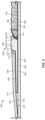
FIG. 1 illustrates an example aircraft in which the example thresholds disclosed herein can be implemented. -
FIG. 2 is a cross-sectional or side view of an example threshold constructed in accordance with the teachings of this disclosure. -
FIG. 3 is a cross-sectional or side view of flooring of the example aircraft ofFIG. 1 with the example threshold ofFIG. 2 . -
FIG. 4A shows an example of serging carpet edge treatment. -
FIG. 4B shows an example of speedbinding carpet edge treatment. -
FIG. 4C shows an example of carpet without edge treatment. -
FIG. 5 is a cross-sectional or side view of another example threshold. -
FIG. 6 is a cross-sectional or side view of another example threshold. -
FIG. 7 is a cross-sectional or side view of another example threshold. -
FIG. 8 is a cross-sectional or side view of another example threshold. -
FIG. 9 is a flowchart representative of an example method of installing flooring materials and an example threshold. - In general, the same reference numbers will be used throughout the drawing(s) and accompanying written description to refer to the same or like parts. The figures are not necessarily to scale. Instead, the thickness of the layers or regions may be enlarged in the drawings. Although the figures show layers and regions with clean lines and boundaries, some or all of these lines and/or boundaries may be idealized. In reality, the boundaries and/or lines may be unobservable, blended, and/or irregular.
- Disclosed herein are example thresholds (sometimes referred to as transition strips) that can be installed at joints between two flooring materials. Thresholds are used to form a smooth transition where the edges of two flooring materials meet. Thresholds are commonly used in aircraft between different flooring sections. For example, the galley of the fuselage often has a mat or plastic flooring, whereas the passenger area of the fuselage has carpet flooring. A threshold can be installed between the edges of the mat and the carpet. The threshold helps to keep the mat and/or the carpet from lifting, as well as provides a smooth transition from one flooring material to the other as they are of different thicknesses
- Known thresholds are relatively bulky and create a noticeable bump between the two flooring materials. This bump can be a nuisance to wheeled-devices such as galley carts, luggage, wheel chairs, knee scooters, etc. Further, known thresholds have long arms that extend over the tops of both flooring materials. These arms form weak points of the threshold that are prone to cracking, chipping, warping, and shrinkage problems.
- Disclosed herein are low profile thresholds that do not create a large bump as seen in known threshold designs. This enables galley carts and other wheeled-devices to easily roll between the two flooring materials without causing a noticeable bump. The example thresholds disclosed herein are also less prone to failure, which reduces costs associated with maintenance of the aircraft. The example thresholds disclosed herein are lighter and constructed of less material than known thresholds. As such, the example thresholds disclosed herein are less expensive to manufacture. The example thresholds disclosed herein can be used for new installations or retrofitted on existing floorings during refreshes (e.g., every 3-6 months).
- An example threshold disclosed herein includes a vertical body portion and a ramp portion. In some examples, the threshold is constructed as a single or unitary part (e.g., a monolithic structure), such as via an extrusion process. In some examples, the threshold is constructed of thermoplastic polyurethane (TPU). The vertical body portion is disposed between the edges of the first and second flooring materials. The ramp portion extends from a first side of the vertical body portion and is installed under the first flooring material (e.g., a mat). The ramp portion has an increasing thickness to raise the first flooring material up closer to the height of the second flooring material (e.g., carpet). The second side surface of the vertical body portion has a concave area (e.g., a cove or recess) that forms a small overhang. An edge of the second flooring material is tucked into the concave area. The small overhang reduces or limits the amount the edge of the second flooring material can be lifted. The overhang is relatively small compared to the arms of known thresholds. This reduces or limits weak points that can lead to cracking.
- While the example thresholds disclosed herein are described in connection with floors in an aircraft, the example thresholds disclosed herein can also be used in connection with any floor. For example, the thresholds can be used in other types of vehicles (e.g., buses, trains, etc.), in residential buildings, in commercial buildings, and/or any other location where thresholds are commonly used between two flooring materials.
-
FIG. 1 illustrates anexample aircraft 100 in which the examples disclosed herein can be implemented. In the illustrated example, theaircraft 100 includes afuselage 102, a first wing 104 (a left wing) coupled to thefuselage 102, a second wing 106 (a right wing) coupled to thefuselage 102, and anempennage 108 at an aft end of thefuselage 102. Theempennage 108 has ahorizontal stabilizer 110 and avertical stabilizer 112. Theaircraft 100 also includes afirst engine 114 carried by thefirst wing 104 and asecond engine 116 carried by thesecond wing 106. In other examples, theaircraft 100 may have multiple engines coupled to each of the first andsecond wings fuselage 102, coupled to theempennage 108, etc.). - The
fuselage 102 of theaircraft 100 carries passengers and/or cargo. Thefuselage 102 may contain one or more floors or levels having flooring. The flooring may include carpets and/or mats, for example. Disclosed herein are example thresholds that can be used between the edges or joints where two flooring materials meet. -
FIG. 2 is a cross-sectional or side view of anexample threshold 200 that can be used in theexample aircraft 100. For example, thethreshold 200 can be used as a transition between two flooring materials (e.g., a mat and carpet) in thefuselage 102 of theaircraft 100. Thethreshold 200 forms a smooth transition between the flooring materials to reduce (e.g., minimize) bumps as well as damage to the flooring materials. - The
threshold 200 has one or more portions or sections. In the illustrated example, thethreshold 200 has avertical body portion 202 and aramp portion 204 coupled to and extending from thevertical body portion 202. When thethreshold 200 is installed between two flooring materials, thevertical body portion 202 is disposed between the edges of the two flooring materials, and theramp portion 204 extends under one of the flooring materials to help raise the flooring material to the same height as the other flooring material. Thethreshold 200 can be constructed to any length (the dimension extending into and out of the page). As shown inFIG. 2 , thevertical body portion 202 has a generally rectangular cross-sectional shape. Thevertical body portion 202 has atop surface 206, abottom surface 208 opposite thetop surface 206, afirst side surface 210, and asecond side surface 212 opposite thefirst side surface 210. - In the illustrated example, the
vertical body portion 202 has aconcave area 214 extending into thesecond side surface 212 at thebottom surface 208. Said another way, thesecond side surface 212 has or forms theconcave area 214 at thebottom surface 208. Theconcave area 214 may also be referred to as a recess or cove. Theconcave area 214 receives an edge of the flooring material, as shown in further detail herein. Theconcave area 214 forms anoverhang 215 on thesecond side surface 212, which extends outward from thetop surface 206. Theoverhang 215 helps prevent the flooring material from lifting, as shown in further detail herein. - As shown in
FIG. 2 , thevertical body portion 202 of thethreshold 200 has afirst edge 216 between thetop surface 206 and thefirst side surface 210. In the illustrated example, thefirst edge 216 is curved or rounded. In some examples, thefirst edge 216 has a constant radius of curvature. Thethreshold 200 also has asecond edge 218 between thetop surface 206 and thesecond side surface 212. In the illustrated example, thesecond edge 218 is curved or rounded. In some examples, thesecond edge 218 has a constant radius of curvature. In some examples, the first andsecond edges second edges top surface 206 of thethreshold 200. - In the illustrated example of
FIG. 2 , thetop surface 206 of thevertical body portion 202 is curved or rounded (e.g., is convex) between thefirst edge 216 and thesecond edge 218. This curved or rounded shape helps address any tolerances between the heights of themat 304 and thecarpet 306 depicted inFIG. 3 . As such, this curved or rounded shape helps provide a smooth transition between the flooring materials. In some examples, thetop surface 206 has a continuous curvature between thefirst edge 216 and thesecond edge 218. In some examples, thetop surface 206 is curved at a constant radius of curvature between thefirst edge 216 and thesecond edge 218. In some examples, the radius of curvature is 50 mm (2 inches). In other examples, the radius of curvature may be larger or smaller. In other examples, thetop surface 206 may be curved at a changing radius of curvature between thefirst edge 216 and thesecond edge 218. - In the illustrated example, the
ramp portion 204 extends from thefirst side surface 210 of thevertical body portion 202 at thebottom surface 208. Theramp portion 204 has atop surface 220, abottom surface 222 opposite thetop surface 220, and adistal end 224. In the illustrated example, thedistal end 224 of theramp portion 204 is rounded or curved. However, in other examples, thedistal end 224 can have sharp corners (e.g., 90° corners). Thebottom surface 222 of theramp portion 204 is continuous with thebottom surface 208 of thevertical body portion 202. Therefore, thebottom surface 222 and thebottom surface 208 form a bottom side orsurface 226 of thethreshold 200. Theramp portion 204 has a decreasing thickness (e.g., height) from the vertical body portion 202 (the ride side inFIG. 2 ) to thedistal end 224 of the ramp portion 204 (the left side inFIG. 2 ). Said another way, theramp portion 204 increases in thickness from thedistal end 224 to thevertical body portion 202. For example, as shown inFIG. 2 , theramp portion 204 has a first thickness T1 at thedistal end 224 and a second thickness T2 at the connection to thevertical body portion 202. The thickness T2 is greater than the thickness T1. This increasing thickness raises the flooring material to a height that is closer to thetop surface 206 of thethreshold 200 and to the other flooring material. - In some examples, the
threshold 200 is constructed of thermoplastic polyurethane (TPU). For example, the threshold can be constructed of Lubrizol ESTANE° 58244, which is an ether based TPU. This type of material has increased durability and dimensional stability. In other examples, thethreshold 200 is constructed of polyvinyl chloride (PVC), such as BMS 8-137. In other examples, thethreshold 200 can be constructed of other types of materials. In this example, thethreshold 200 is constructed as a single or monolithic structure. For example, thethreshold 200 may be manufactured via an extrusion process or molding process. In other examples, thethreshold 200 can be constructed of two or more separate portions (e.g., thevertical body portion 202 and the ramp portion 204) that are coupled together (e.g., via a joining process) to form thethreshold 200. Thethreshold 200 can be constructed as any length depending on the length of the edges of the flooring materials. - Various dimensions are shown in
FIG. 2 . Thethreshold 200 has an overall height of H1 between thebottom surface 226 and thetop surface 206. Thefirst side surface 210 has a height of H2 between thetop surface 220 of theramp portion 204 and thetop surface 206 of thevertical body portion 202. Thebottom surface 226 of thethreshold 200 has a width W1. Thevertical body portion 202 has a width W2. Theramp portion 204 increases in thickness from T1 to T2. Theoverhang 215 has a width W3 and a height H3. The dimension can be based on the type and/or thicknesses of the flooring materials between which a transition is needed. In some examples, the ratio W1/W2 is greater than 2 or 3. This is because theramp portion 204 is relatively wide (in the horizontal direction) compared to the vertical body portion. In some examples, having a larger width W1 provides a sufficient lower surface for adhesive or double-sided tape widths, while also providing enough material to be tucked under the flooring material (e.g., a mat) to help hold thethreshold 200 down, which provides more stability and rigidity to thethreshold 200. This also results in a longer, more gradual rise in the height of the flooring material, which reduces (e.g., minimizes) noticeable bumps in the flooring. In some examples, having a smaller width W2 is advantageous for aesthetic purposes, because it reduces (e.g., minimizes) the amount of plastic that is visible (more plastic is generally less aesthetically pleasing). -
FIG. 3 is a cross-sectional view of a portion of afloor 300 in the fuselage 102 (FIG. 1 ) of the aircraft 100 (FIG. 1 ) in which thethreshold 200 is used. In the illustrated example, thefloor 300 includes asubfloor 302 upon which one on more flooring materials are layered. Thesubfloor 302 may be constructed of one or more floor panels of various materials. In some examples, thesubfloor 302 is a constructed of a composite material, such as a honeycomb core with graphite or fiberglass plies on the top and bottom. In other examples, thesubfloor 302 can be constructed of other materials (e.g., wood, plastic, etc.). - The
floor 300 of theaircraft 100 includes afirst flooring material 304 on thesubfloor 302 and asecond flooring material 306 on thesubfloor 302. In this example, thefirst flooring material 304 is a mat (e.g., a vinyl mat), referred to herein as themat 304, and thesecond flooring material 306 is carpet, referred to herein as thecarpet 306. Thethreshold 200 is at least partially disposed between themat 304 and thecarpet 306 and provides a smooth transition between themat 304 and thecarpet 306. For example, themat 304 may be the flooring in the galley of the fuselage 102 (FIG. 1 ) and thecarpet 306 may be the flooring in the passenger seating area of thefuselage 102. Thethreshold 200 provides a smooth transition between these two different flooring materials and areas of thefuselage 102. In some examples, themat 304 and thecarpet 306 have different heights or thicknesses relative to thesubfloor 302. Therefore, thethreshold 200 also provides a smooth transition between the two different heights. In other examples, the first andsecond flooring materials - In the illustrated example, the
threshold 200 is disposed on thesubfloor 302. In some examples, thethreshold 200 is coupled to thesubfloor 302 via an adhesive. For example, as shown inFIG. 3 , anadhesive layer 308 is disposed between thebottom surface 226 of thethreshold 200 and thesubfloor 302. Theadhesive layer 308 holds thethreshold 200 in position on thesubfloor 302. In some examples, theadhesive layer 308 is tape, such as a double-sided tape (e.g., BMS 5-133 Type II, Class 2 tape). In some examples, theadhesive layer 308 is a self-adhesive layer on thebottom surface 226 of thethreshold 200. In other examples, other types of adhesives can be used (e.g., glue). In still other examples, no adhesive layer is used. Instead, thebottom surface 226 of thethreshold 200 can be in direct contact with thesubfloor 302 and/or coupled to thesubfloor 302 via other mechanisms (e.g., nails, screws, etc.). - The
mat 304 has atop surface 310, abottom surface 312, and afirst edge 314. Thecarpet 306 has atop surface 316, abottom surface 318, and a second edge 320. In some examples, the thickness of themat 304 and thecarpet 306 are different. For example, inFIG. 3 , themat 304 has a smaller thickness than thecarpet 306. Thethreshold 200 is at least partially disposed between theedges 314, 320 of themat 304 and thecarpet 306 and used to create a smooth transition between the two types of flooring and their respective heights. - In the illustrated example, a portion of the
mat 304 is disposed on or over theramp portion 204 of thethreshold 200. Said another way, theramp portion 204 is between a portion of themat 304 and thesubfloor 302. In some examples, the weight of the portion of themat 304 on theramp portion 204 helps hold thethreshold 200 in place. Further, as discussed above, themat 304 may be thinner than thecarpet 306. Therefore, theramp portion 204 provides a gradual increase to the height of themat 304 so thetop surface 310 of themat 304 is closer to or the same as the height of thetop surface 206 of thethreshold 200 and thetop surface 316 of thecarpet 306. This enables wheeled-devices to easily and smoothly roll between the two flooring materials. - In some examples, the
mat 304 is coupled to thesubfloor 302 via an adhesive layer. For example,FIG. 3 shows an exampleadhesive layer 322 on thebottom surface 312 of themat 304. Theadhesive layer 322 helps themat 304 stick to thesubfloor 302 to prevent or limit movement. Also, as shown inFIG. 3 , theadhesive layer 322 is also between thebottom surface 312 of themat 304 and thetop surface 220 of theramp portion 204. This helps thethreshold 200 remain coupled to themat 304 and reduces or limits relative movement between themat 304 and thethreshold 200. In some examples, theadhesive layer 322 is a self-adhesive layer that is manufactured with themat 304, and a liner is provided over the self-adhesive layer. Before installing themat 304, the liner is removed to expose the self-adhesive layer. In other examples, theadhesive layer 322 can be another type of adhesive, such as a tape (e.g., double-sided tape). - In some examples, the
first edge 314 of themat 304 does not extend all the way to thefirst side surface 210 of thevertical body portion 202 of thethreshold 200. As shown inFIG. 3 , asealant 324 is disposed between thefirst edge 314 of themat 304 and thefirst side surface 210 of thevertical body portion 202. Thesealant 324 may be, for example, BAC5010 TY 60 (RTV108 - Silicone Sealant), BMS5-142, BMS5-45, or another type of sealant. Thesealant 324 fills the gap or space between thefirst edge 314 of themat 304 and thefirst side surface 210 of thethreshold 200 to provide a smooth transition between thetop surface 310 of themat 304 and thetop surface 206 of thethreshold 200. Thesealant 324 also prevents liquids from getting underneath themat 304. - In the illustrated example, the second edge 320 of the
carpet 306 extends into (e.g., is tucked into) theconcave area 214 formed on thesecond side surface 212 of thethreshold 200. In some examples, the second edge 320 of thecarpet 306 is in contact with thesecond side surface 212 of thethreshold 200. As shown inFIG. 3 , the second edge 320 of thecarpet 306 is rounded or curved. In some examples, the second edge 320 of thecarpet 306 is edge treated, which helps prevent thecarpet 306 from fraying.FIGS. 4A and 4B show two example edge treatments for thecarpet 306, including serging and speedbinding. In other examples, other types of edge treatments can be implemented. In other examples, such as shown inFIG. 4C , no edge treatment may be provided. Referring back toFIG. 3 , in some examples, thecarpet 306 is coupled to the subfloor via anadhesive layer 326. In some examples, thecarpet 306 is manufactured with a self-adhesive layer or sticky dots on thebottom surface 318 and covered with a liner. Before installing thecarpet 306, the liner is removed, and then thecarpet 306 can be pressed onto thesubfloor 302. - As shown in
FIG. 3 , the second edge 320 of thecarpet 306 is disposed in theconcave area 214. As such, theoverhang 215 of thethreshold 200 is above (e.g., overhangs) a portion of thecarpet 306. Theoverhang 215 limits or prevents the second edge 320 of thecarpet 306 from being lifted away from thesubfloor 302. The design of theconcave area 214 and theoverhang 215 also reduces (e.g., minimizes) or limits any gaps between thethreshold 200 and thecarpet 306. Theoverhang 215 is relatively small compared to known thresholds that have long arms that extend over the top of thecarpet 306. In some examples, theoverhang 215 has a width W3 (FIG. 2 ) of less than about 2.540 mm (0.100 inches) (e.g., ±0.25 mm or 0.01 inches) in the horizontal direction. Known thresholds that have long arms extend about 25 mm (1 inch) or more in the horizontal direction. Therefore, in some examples, theoverhang 215 is about 1/10th the size of a traditional arm on a threshold. Having a smaller overhang reduces or eliminates weak points for cracking and/or lifting. In other examples, theoverhang 215 can have a width W3 that is greater than 2.540 mm (0.100 inches). The width W3 may depend on the type and/or size of flooring material. - As shown in
FIG. 3 , thetop surface 206 of thethreshold 200 provides a smooth transition between thetop surface 310 of themat 304 and thetop surface 316 of thecarpet 306. The transition is relatively low and does not cause a noticeable bump as seen in known thresholds. This enables wheeled-devices to easily cross over the transition between themat 304 and thecarpet 306. This also reduces impacts and therefore wear and tear on thethreshold 200, and thereby improves the life of thethreshold 200. - As disclosed above, the various dimensions of the
threshold 200 can be selected based on the type and/or size of the flooring materials. In some examples, thethreshold 200 is dimensioned to be used with a range of flooring material thicknesses. For example, assume themat 304 has a minimum thickness of 1.50 mm (0.059 inches (")) and a maximum thickness for 3.35 mm (0.132"), and thecarpet 306 has a minimum thickness of 3.55 mm (0.14") and a maximum thickness of 12.0 mm (0.47"). In such an example, referring toFIG. 2 , the overall height H1 is 4.3 mm (0.17"), the height H2 is 2.8 mm (0.11"), the width W1 is 35.5 mm (1.4"), the width W2 is 10.2 mm (0.40"), the thickness T1 is 1.0 mm (0.04"), the thickness T2 is 1.5 mm (0.06"), the width W3 of theoverhang 215 is 25.4 mm (0.100"), and the height H3 of theoverhang 215 is 3.12 mm (0.123"). These dimensions enable thethreshold 200 to be used with mats and carpeting having the above-noted ranges of thicknesses, which are commonly found on aircraft. However, in other examples, thethreshold 200 can be constructed to have different dimensions. For instance, with thicker/taller carpets, the thickness T1 and the height H1 may be larger. As another example, the height H3 of theoverhang 215 may be larger or smaller depending on the thickness of the carpet. In some examples, the height H3 of theoverhang 215 may be in the range of 3.12 mm-10.2 mm (0.123"- 0.400"). - In the illustrated example, the
threshold 200 has theoverhang 215 on one side and theramp portion 204 on the opposite side. In this example, thefirst side surface 210 of thevertical body portion 202 does not have an overhang or arm that overhangs themat 304. Further, thesecond side surface 212 does not have a ramp portion that extends below thecarpet 306. Therefore, thethreshold 200 has an overhang on one side and a ramp portion on the opposite side. This minimal design results in less material and, thus, is lighter and less expensive to manufacture. However, in other examples, thethreshold 200 may have overhangs and/or ramps on both sides. -
FIGS. 5-8 illustrate other example thresholds that may be implemented in theaircraft 100 between themat 304 and thecarpet 306. The example thresholds are similar to thethreshold 200, except as noted below and shown in the figures. Any of the example aspects (e.g., dimensions, materials, etc.) disclosed in connection with thethreshold 200 can likewise apply to the thresholds inFIGS. 5-8 . -
FIG. 5 shows anexample threshold 500 having avertical body portion 502 and aramp portion 504. Thevertical body portion 500 has afirst surface side 506 and asecond side surface 508. In this example, thefirst side 506 has anoverhang 510. Therefore, when themat 304 is installed, theoverhang 510 is above or overhangs a portion of themat 304. This limits or prevents themat 304 from lifting. Further, as shown inFIG. 5 , aconcave area 512 is formed on thesecond side surface 508. Theconcave area 512 is larger than theconcave area 214 disclosed above. Therefore, thevertical body portion 502 forms alarger arm 514 that overhangs the carpet 306 (FIG. 3 ). -
FIG. 6 shows anexample threshold 600 that has a substantially similar shape as thethreshold 200 inFIGS. 2 and3 . However, inFIG. 6 , thethreshold 600 has achannel 602 extending into abottom surface 604 of avertical body portion 606. Thechannel 602 helps to keep the thickness of thethreshold 600 more constant throughout the extrusion process, which helps to improve extension quality (e.g., minimizes potential flows due to cooling rates and material flows). Thechannel 602 also helps to reduce (e.g., minimize) material usage and weight. -
FIG. 7 shows anexample threshold 700 having avertical body portion 702 and aramp portion 704. Thevertical body portion 702 and theramp portion 704 are similar to thevertical body portion 202 and theramp portion 204 disclosed above. However, in this example, theramp portion 704 is relatively wide (in the horizontal direction ofFIG. 7 ) compared to the width of thevertical body portion 702. Further, thevertical body portion 702 is relatively short compared to other vertical body portions. Therefore, thethreshold 700 can be advantageous for use with thinner flooring materials. The longer ramp provides a more gradual increase or slope for the flooring material. -
FIG. 8 shows anexample threshold 800 having avertical body portion 802 and aramp portion 804. Thethreshold 800 is substantially the same as thethreshold 700 ofFIG. 7 . However, thethreshold 800 has a shorter ramp portion. Also, thevertical body portion 802 is higher. Therefore, thisthreshold 800 is advantageous for use with thicker flooring materials. -
FIG. 9 is a flowchart representative of anexample method 900 of installing flooring materials and theexample threshold 200 in an aircraft, such as theaircraft 100. Theexample method 900 is disclosed in connection with themat 304 as the first flooring material and thecarpet 306 as the second flooring material. However, the example method can be similarly performed in connection with other types of flooring materials. Further, theexample method 900 can be implemented in connection with other types of thresholds, such as the thresholds ofFIGS. 5-8 . - At
block 902, themethod 900 includes positioning themat 304 in the desired location on thesubfloor 302, such as by one or more installer(s). Then, the installer(s) adhere a first portion of themat 304 to thesubfloor 302. For example, the installer(s) can lift back a corner or section of themat 304 and peel away the liner to expose the adhesive layer 322 (e.g., the self-adhesive layer). Themat 304 can then be laid back on thesubfloor 302 to adhere the first portion of themat 304 to thesubfloor 302. All of themat 304 is adhered to thesubfloor 302 except a second portion along thefirst edge 314. In some examples, the liner is kept on the bottom of themat 304 along the second portion so themat 304 does not accidently adhere to thesubfloor 302. In other examples, themat 304 may be adhered to thesubfloor 302 using a double-sided tape that does not come already installed on themat 304. - At
block 904, themethod 900 includes positioning thethreshold 200 in the desired location along near thefirst edge 314 of themat 304. In some examples, thethreshold 200 can be adhere to thesubfloor 302 with theadhesive layer 308. In some examples, theadhesive layer 308 is double-sided tape. In such an example, the double-side tape can be adhered to thebottom surface 226 of thethreshold 200 first, and then thethreshold 200 can be adhered to thesubfloor 302. In other examples, theadhesive layer 308 may be a self-adhesive layer already on thebottom surface 226 of thethreshold 200. Therefore, themethod 900 may include positioning thethreshold 200, peeling off a liner that covers the self-adhesive layer, and then adhering thethreshold 200 to thesubfloor 302. In some examples, prior to adhering thethreshold 200, thesubfloor 302 is prepared by vacuuming and/or applying a solvent cleaner to help ensure a good bond. - At
block 906, themethod 900 includes peeling off the liner from themat 304 and adhering the second portion of themat 304 on top of theramp portion 204 of thethreshold 200, such that thefirst edge 314 of themat 304 is adjacent thefirst side surface 210 of thevertical body portion 202. As such, themat 304 is coupled to theramp portion 204 of thethreshold 200. - At
block 908, themethod 900 includes positioning the carpet 305 in the desired location on thesubfloor 302. Thecarpet 306 is positioned such that the second edge 320 extends under theoverhang 215 of thethreshold 200. Then, the installer(s) adhere thecarpet 306 to the subfloor 302 (e.g., via the adhesive layer 326) and tuck the second edge 320 of thecarpet 306 into the concave area 214 (and under the overhang 215) of thethreshold 200. Theadhesive layer 326 may be a self-adhesive layer or double-sided tape, for example. - At
block 910, themethod 900 includes adding thesealant 324 between thefirst edge 314 of themat 304 and thefirst side surface 210 of thevertical body portion 202. - In other examples, the flooring materials and the
threshold 200 can be installed in a different order or sequence. For example, thecarpet 306 can be installed before themat 304. - As used herein, unless otherwise stated, the term "above" describes the relationship of two parts relative to Earth. A first part is above a second part, if the second part has at least one part between Earth and the first part. Likewise, as used herein, a first part is "below" a second part when the first part is closer to the Earth than the second part. As noted above, a first part can be above or below a second part with one or more of: other parts therebetween, without other parts therebetween, with the first and second parts touching, or without the first and second parts being in direct contact with one another.
- As used in this patent, stating that any part (e.g., a layer, film, area, region, or plate) is in any way on (e.g., positioned on, located on, disposed on, or formed on, etc.) another part, indicates that the referenced part is either in contact with the other part, or that the referenced part is above the other part with one or more intermediate part(s) located therebetween.
- As used herein, connection references (e.g., attached, coupled, connected, and joined) may include intermediate members between the elements referenced by the connection reference and/or relative movement between those elements unless otherwise indicated. As such, connection references do not necessarily infer that two elements are directly connected and/or in fixed relation to each other. As used herein, stating that any part is in "contact" with another part is defined to mean that there is no intermediate part between the two parts.
- Unless specifically stated otherwise, descriptors such as "first," "second," "third," etc., are used herein without imputing or otherwise indicating any meaning of priority, physical order, arrangement in a list, and/or ordering in any way, but are merely used as labels and/or arbitrary names to distinguish elements for ease of understanding the disclosed examples. In some examples, the descriptor "first" may be used to refer to an element in the detailed description, while the same element may be referred to in a claim with a different descriptor such as "second" or "third." In such instances, it should be understood that such descriptors are used merely for identifying those elements distinctly within the context of the discussion (e.g., within a claim) in which the elements might, for example, otherwise share a same name.
- As used herein, "approximately" and "about" modify their subjects/values to recognize the potential presence of variations that occur in real world applications. For example, "approximately" and "about" may modify dimensions that may not be exact due to manufacturing tolerances and/or other real world imperfections as will be understood by persons of ordinary skill in the art. For example, "approximately" and "about" may indicate such dimensions may be within a tolerance range of +/- 10% unless otherwise specified in the below description.
- "Including" and "comprising" (and all forms and tenses thereof) are used herein to be open ended terms. Thus, whenever a claim employs any form of "include" or "comprise" (e.g., comprises, includes, comprising, including, having, etc.) as a preamble or within a claim recitation of any kind, it is to be understood that additional elements, terms, etc., may be present without falling outside the scope of the corresponding claim or recitation. As used herein, when the phrase "at least" is used as the transition term in, for example, a preamble of a claim, it is open-ended in the same manner as the term "comprising" and "including" are open ended. The term "and/or" when used, for example, in a form such as A, B, and/or C refers to any combination or subset of A, B, C such as (1) A alone, (2) B alone, (3) C alone, (4) A with B, (5) A with C, (6) B with C, or (7) A with B and with C. As used herein in the context of describing structures, components, items, objects and/or things, the phrase "at least one of A and B" is intended to refer to implementations including any of (1) at least one A, (2) at least one B, or (3) at least one A and at least one B. Similarly, as used herein in the context of describing structures, components, items, objects and/or things, the phrase "at least one of A or B" is intended to refer to implementations including any of (1) at least one A, (2) at least one B, or (3) at least one A and at least one B. As used herein in the context of describing the performance or execution of processes, instructions, actions, activities, etc., the phrase "at least one of A and B" is intended to refer to implementations including any of (1) at least one A, (2) at least one B, or (3) at least one A and at least one B. Similarly, as used herein in the context of describing the performance or execution of processes, instructions, actions, activities, etc., the phrase "at least one of A or B" is intended to refer to implementations including any of (1) at least one A, (2) at least one B, or (3) at least one A and at least one B.
- As used herein, singular references (e.g., "a", "an", "first", "second", etc.) do not exclude a plurality. The term "a" or "an" object, as used herein, refers to one or more of that object. The terms "a" (or "an"), "one or more", and "at least one" are used interchangeably herein. Furthermore, although individually listed, a plurality of means, elements, or actions may be implemented by, e.g., the same entity or object. Additionally, although individual features may be included in different examples or claims, these may possibly be combined, and the inclusion in different examples or claims does not imply that a combination of features is not feasible and/or advantageous.
- From the foregoing, it will be appreciated that example systems, apparatus, articles of manufacture, and methods have been disclosed that provide a smooth transition between two flooring materials. The example low profile thresholds disclosed herein reduce or eliminate the noticeable bump or discontinuity in height between the two flooring materials. This reduces or eliminates difficulties with moving wheeled-devices over the threshold. The example thresholds disclosed herein are lighter, use less material, are less prone to failure, and result in great cost savings than known threshold.
- Examples and combinations of examples disclosed herein include the following:
- Example 1 is an aircraft comprising a subfloor, first flooring material on the subfloor, the first flooring material having a first edge, second flooring material on the subfloor, the second flooring material having a second edge, and a threshold at least partially between the first flooring material and the second flooring material. The threshold includes a vertical body portion having a top surface, a bottom surface opposite the top surface, a first side surface, and a second side surface opposite the first side surface. The vertical body portion has a concave area extending into the second side surface at the bottom surface, wherein the second edge of the second flooring material extends into the concave area. The threshold also includes a ramp portion extending from the first side surface. The ramp portion has a decreasing thickness from the vertical body portion to a distal end of the ramp portion. The ramp portion is positioned between a portion of the first flooring material and the subfloor.
- Example 2 includes the aircraft of Example 1, wherein the concave area forms an overhang on the second side surface, the overhang having of a width of less than 2.54 mm (0.100 inches).
- Example 3 includes the aircraft of Examples 1 or 2, wherein the threshold is constructed of thermoplastic polyurethane (TPU).
- Example 4 includes the aircraft of any of Examples 1-3, wherein the threshold is a monolithic structure.
- Example 5 includes the aircraft of any of Examples 1-4, wherein the vertical body portion has a first edge between the top surface and the first side surface and a second edge between the top surface and the second side surface, and wherein the top surface of the vertical body portion is curved between the first edge of the vertical body portion and the second edge of the vertical body portion.
- Example 6 includes the aircraft of Example 5, wherein the first edge of the vertical body portion is rounded and the second edge of the vertical body portion is rounded.
- Example 7 includes the aircraft of any of Examples 1-6, further including an adhesive layer between the bottom surface of the threshold and the subfloor.
- Example 8 includes the aircraft of Example 7, wherein the adhesive layer is double-sided tape.
- Example 9 includes the aircraft of any of Examples 1-8, further including an adhesive layer between the first flooring material and a top surface of the ramp portion.
- Example 10 includes the aircraft of any of Examples 1-9, further including a sealant between the first edge of the first flooring material and the first side surface of the vertical body portion.
- Example 11 includes the aircraft of any of Examples 1-10, wherein the first flooring material is a mat and the second flooring material is carpet.
- Example 12 includes the aircraft of Example 11, wherein the second edge of the carpet is edge treated.
- Example 13 is a threshold to be installed between two flooring materials, the threshold comprising a vertical body portion having a top surface, a bottom surface opposite the top surface, a first side surface, and a second side surface opposite the first side surface. The second side surface has a concave area at the bottom surface to receive an edge of a flooring material. The concave area forms an overhang on the second side surface. The threshold also includes a ramp portion extending from the first side surface. The ramp portion has a decreasing thickness from the vertical body portion to a distal end of the ramp portion.
- Example 14 includes the threshold of Example 13, wherein the vertical body portion has a first edge between the top surface and the first side surface and a second edge between the top surface and the second side surface, and wherein the top surface of the vertical body portion is curved between the first edge of the vertical body portion and the second edge of the vertical body portion.
- Example 15 includes the threshold of Example 14, wherein the first edge of the vertical body portion is rounded and the second edge of the vertical body portion is rounded.
- Example 16 includes the threshold of any of Examples 13-15, wherein the threshold is constructed of thermoplastic polyurethane (TPU).
- Example 17 includes the threshold of any of Examples 13-16, wherein the first side surface does not include an overhang.
- Example 18 is a method of installing flooring materials and a threshold in an aircraft, the method comprising adhering a first portion of a first flooring material to a subfloor in the aircraft, and adhering the threshold to the subfloor near a first edge of the first flooring material. The threshold includes a vertical body portion having a top surface, a bottom surface opposite the top surface, a first side surface, and a second side surface opposite the first side surface. The vertical body portion has a concave area extending into the second side surface at the bottom surface and a ramp portion extending from the first side surface, the ramp portion having a decreasing thickness from the vertical body portion to a distal end of the ramp portion. The method also includes adhering a second portion of the first flooring material on top of the ramp portion of the threshold such that the first edge of the first flooring material is adjacent the first side surface of the vertical body portion, and adhering a second flooring material to the subfloor and tucking a second edge of the second flooring material into the concave area of the threshold.
- Example 19 includes the method of Example 18, further including adding a sealant between the first edge of the first flooring material and the first side surface of the vertical body portion of the threshold.
- Example 20 includes the method of Examples 18 or 19, wherein the concave area forms an overhang on the second side surface of the vertical body portion, the overhang being disposed above a portion of the second flooring material.
- The following claims are hereby incorporated into this Detailed Description by this reference. Although certain example systems, apparatus, articles of manufacture, and methods have been disclosed herein, the scope of coverage of this patent is not limited thereto. On the contrary, this patent covers all systems, apparatus, articles of manufacture, and methods fairly falling within the scope of the claims of this patent.
Claims (15)
- An aircraft (100) comprising:a subfloor (302);first flooring material (304) on the subfloor (302), the first flooring material (304) having a first edge (314);second flooring material (306) on the subfloor (302), the second flooring material (306) having a second edge (320); anda threshold (200) at least partially between the first flooring material (304) and the second flooring material (306), the threshold (200) including:a vertical body portion (202) having a top surface (206), a bottom surface (208) opposite the top surface (206), a first side surface (210), and a second side surface (212) opposite the first side surface (210), the vertical body portion (202) having a concave area (214) extending into the second side surface (212) at the bottom surface (208), wherein the second edge (320) of the second flooring material (306) extends into the concave area (214); anda ramp portion (204) extending from the first side surface (210), the ramp portion (204) having a decreasing thickness from the vertical body portion (202) to a distal end (224) of the ramp portion (204), the ramp portion (204) positioned between a portion of the first flooring material (304) and the subfloor (302).
- The aircraft (100) of claim 1, wherein the concave area (214) forms an overhang (215) on the second side surface (212), the overhang (215) having of a width of less than 2.54 mm.
- The aircraft (100) of claim 1 or 2, wherein the threshold (200) is a monolithic structure.
- The aircraft (100) of anyone of claims 1-3, wherein the vertical body portion (202) has a first edge (216) between the top surface (206) and the first side surface (210) and a second edge (218) between the top surface (206) and the second side surface (212), and wherein the top surface (206) of the vertical body portion (202) is curved between the first edge (216) of the vertical body portion (202) and the second edge (218) of the vertical body portion (202); and
wherein the first edge (216) of the vertical body portion (202) is rounded and the second edge (218) of the vertical body portion (202) is rounded. - The aircraft (100) of anyone of claims 1-4, further including an adhesive layer (308) between the bottom surface (226) of the threshold (200) and the subfloor (302).
- The aircraft (100) of anyone of claims 1-5, further including an adhesive layer (322) between the first flooring material (304) and a top surface (220) of the ramp portion (204).
- The aircraft (100) of anyone of claims 1-6, further including a sealant (324) between the first edge (314) of the first flooring material (304) and the first side surface (210) of the vertical body portion (202).
- The aircraft (100) of anyone of claims 1-7, wherein the first flooring material (304) is a mat and the second flooring material (306) is carpet.
- The aircraft (100) of claim 8, wherein the second edge (320) of the carpet is edge treated.
- A threshold (200) to be installed between two flooring materials, the threshold (200) comprising:a vertical body portion (202) having a top surface (206), a bottom surface (208) opposite the top surface (206), a first side surface (210), and a second side surface (212) opposite the first side surface (210), the second side surface (212) having a concave area (214) at the bottom surface (208) to receive an edge of a flooring material, the concave area (214) forming an overhang (215) on the second side surface (212); anda ramp portion (204) extending from the first side surface (210), the ramp portion (204) having a decreasing thickness from the vertical body portion (202) to a distal end (224) of the ramp portion (204).
- The threshold (200) of claim 10, wherein the vertical body portion (202) has a first edge (216) between the top surface (206) and the first side surface (210) and a second edge (218) between the top surface (206) and the second side surface (212), and wherein the top surface (206) of the vertical body portion (202) is curved between the first edge (216) of the vertical body portion (202) and the second edge (218) of the vertical body portion (202).
- The threshold (200) of claim 11, wherein the first edge (216) of the vertical body portion (202) is rounded and the second edge (218) of the vertical body portion (202) is rounded.
- The threshold (200) of anyone of claims 10-12, wherein the threshold (200) is constructed of thermoplastic polyurethane (TPU).
- A method of installing flooring materials and a threshold (200) in an aircraft (100), the method comprising:adhering a first portion of a first flooring material (304) to a subfloor (302) in the aircraft (100);adhering the threshold (200) to the subfloor (302) near a first edge (314) of the first flooring material (304), the threshold (200) including:a vertical body portion (202) having a top surface (206), a bottom surface (208) opposite the top surface (206), a first side surface (210), and a second side surface (212) opposite the first side surface (210), the vertical body portion (202) having a concave area (214) extending into the second side surface (212) at the bottom surface (208); anda ramp portion (204) extending from the first side surface (210), the ramp portion (204) having a decreasing thickness from the vertical body portion (202) to a distal end (224) of the ramp portion (204);adhering a second portion of the first flooring material (304) on top of the ramp portion (204) of the threshold (200) such that the first edge (314) of the first flooring material (304) is adjacent the first side surface (210) of the vertical body portion (202); andadhering a second flooring material (306) to the subfloor (302) and tucking a second edge (320) of the second flooring material (306) into the concave area (214) of the threshold (200).
- The method of claim 14, further including adding a sealant (324) between the first edge (314) of the first flooring material (304) and the first side surface (210) of the vertical body portion (202) of the threshold (200).
Applications Claiming Priority (1)
| Application Number | Priority Date | Filing Date | Title |
|---|---|---|---|
| US18/449,869 US20250058866A1 (en) | 2023-08-15 | 2023-08-15 | Thresholds for Flooring in an Aircraft |
Publications (1)
| Publication Number | Publication Date |
|---|---|
| EP4509399A1 true EP4509399A1 (en) | 2025-02-19 |
Family
ID=91759418
Family Applications (1)
| Application Number | Title | Priority Date | Filing Date |
|---|---|---|---|
| EP24185798.6A Withdrawn EP4509399A1 (en) | 2023-08-15 | 2024-07-01 | Thresholds for flooring in an aircraft |
Country Status (4)
| Country | Link |
|---|---|
| US (1) | US20250058866A1 (en) |
| EP (1) | EP4509399A1 (en) |
| JP (1) | JP2025027974A (en) |
| CN (1) | CN119489920A (en) |
Citations (4)
| Publication number | Priority date | Publication date | Assignee | Title |
|---|---|---|---|---|
| DE20017532U1 (en) * | 2000-10-12 | 2001-08-30 | Stolle, Pierre Marcel, 30855 Langenhagen | A transition profile and sealing and fixing system for bridging joints and for fixing floor coverings, preferably in the aircraft |
| WO2016111839A1 (en) * | 2015-01-05 | 2016-07-14 | Lti Flexible Products, Inc. | Floor covering transition |
| CN112647314A (en) * | 2020-12-28 | 2021-04-13 | 天津云瑞地毯股份有限公司 | Thickened environment-friendly carpet and production process thereof |
| US20220349187A1 (en) * | 2020-08-26 | 2022-11-03 | Wearwell, Llc | Integrated mat assembly and method of use |
Family Cites Families (3)
| Publication number | Priority date | Publication date | Assignee | Title |
|---|---|---|---|---|
| GB2276317B (en) * | 1993-03-26 | 1996-08-21 | John Graham Law | Trim for floorcoverings |
| US8844231B2 (en) * | 2011-10-28 | 2014-09-30 | Richard W. URBAN, JR. | Shim device and method of floor leveling |
| CA2913263A1 (en) * | 2014-11-24 | 2016-05-24 | Tarkett Usa Inc. | Transition for vinyl tile and carpet tile |
-
2023
- 2023-08-15 US US18/449,869 patent/US20250058866A1/en active Pending
-
2024
- 2024-06-27 JP JP2024103441A patent/JP2025027974A/en active Pending
- 2024-07-01 EP EP24185798.6A patent/EP4509399A1/en not_active Withdrawn
- 2024-08-14 CN CN202411114974.2A patent/CN119489920A/en active Pending
Patent Citations (4)
| Publication number | Priority date | Publication date | Assignee | Title |
|---|---|---|---|---|
| DE20017532U1 (en) * | 2000-10-12 | 2001-08-30 | Stolle, Pierre Marcel, 30855 Langenhagen | A transition profile and sealing and fixing system for bridging joints and for fixing floor coverings, preferably in the aircraft |
| WO2016111839A1 (en) * | 2015-01-05 | 2016-07-14 | Lti Flexible Products, Inc. | Floor covering transition |
| US20220349187A1 (en) * | 2020-08-26 | 2022-11-03 | Wearwell, Llc | Integrated mat assembly and method of use |
| CN112647314A (en) * | 2020-12-28 | 2021-04-13 | 天津云瑞地毯股份有限公司 | Thickened environment-friendly carpet and production process thereof |
Also Published As
| Publication number | Publication date |
|---|---|
| CN119489920A (en) | 2025-02-21 |
| JP2025027974A (en) | 2025-02-28 |
| US20250058866A1 (en) | 2025-02-20 |
Similar Documents
| Publication | Publication Date | Title |
|---|---|---|
| US5154961A (en) | Floor mat and method of making same | |
| EP3725670B1 (en) | Floor covering systems in an aircraft and methods for installation | |
| US6656562B2 (en) | Slip resistant mat | |
| US10919612B2 (en) | Floor panels and flooring systems for a passenger vehicle, and methods for installation | |
| US4840824A (en) | Stairtread facings and a co-extrusion method for their manufacture | |
| CA2417238A1 (en) | Continuous foam rug gripper and method of using the same | |
| US10391720B2 (en) | Method for making a slip resistant mat | |
| US5376419A (en) | Method and apparatus for seaming carpets | |
| JP4999218B2 (en) | Privacy and support equipment | |
| US20250058866A1 (en) | Thresholds for Flooring in an Aircraft | |
| CN101573278B (en) | Passenger conveyor handrail with a unique sliding layer and manufacture method | |
| US20040074698A1 (en) | Removable tread mat for open riser stairs | |
| CN108367895A (en) | Stair lift or relative improvement | |
| NL2026988B1 (en) | Panel, in particular a floor, ceiling, or wall panel; a covering constructed by a multitude of such panels; and a method for the recycling of such a panel | |
| US6866916B1 (en) | Slip resistant mat and process of manufacture of same | |
| US20080023977A1 (en) | Vehicle floor covering system | |
| CN212097782U (en) | A non-slip car carpet | |
| AU2013349192A1 (en) | Method for producing endless belt, and endless belt | |
| EP0891146A1 (en) | A floor strip system for levelling the transition between two abutting floorings | |
| KR20180003029A (en) | Floor carpet for vehicle | |
| JP6419145B2 (en) | Slip-resistant mat with moisture passage | |
| US11130317B2 (en) | Hybrid underlayment for non textile floor covering | |
| GB2537640A (en) | A vehicle flooring system | |
| CN214189410U (en) | Handrail structure, car handrail and car | |
| CN215799296U (en) | Elevator carpet adhesive tape with strong wear resistance |
Legal Events
| Date | Code | Title | Description |
|---|---|---|---|
| PUAI | Public reference made under article 153(3) epc to a published international application that has entered the european phase |
Free format text: ORIGINAL CODE: 0009012 |
|
| STAA | Information on the status of an ep patent application or granted ep patent |
Free format text: STATUS: THE APPLICATION HAS BEEN PUBLISHED |
|
| AK | Designated contracting states |
Kind code of ref document: A1 Designated state(s): AL AT BE BG CH CY CZ DE DK EE ES FI FR GB GR HR HU IE IS IT LI LT LU LV MC ME MK MT NL NO PL PT RO RS SE SI SK SM TR |
|
| STAA | Information on the status of an ep patent application or granted ep patent |
Free format text: STATUS: THE APPLICATION IS DEEMED TO BE WITHDRAWN |
|
| 18D | Application deemed to be withdrawn |
Effective date: 20250820 |