EP4509356A1 - Self-actuating ergonomic secondary support handle assembly for large machines - Google Patents
Self-actuating ergonomic secondary support handle assembly for large machines Download PDFInfo
- Publication number
- EP4509356A1 EP4509356A1 EP24189057.3A EP24189057A EP4509356A1 EP 4509356 A1 EP4509356 A1 EP 4509356A1 EP 24189057 A EP24189057 A EP 24189057A EP 4509356 A1 EP4509356 A1 EP 4509356A1
- Authority
- EP
- European Patent Office
- Prior art keywords
- secondary support
- support handle
- plate
- door
- handle assembly
- Prior art date
- Legal status (The legal status is an assumption and is not a legal conclusion. Google has not performed a legal analysis and makes no representation as to the accuracy of the status listed.)
- Granted
Links
Images



Classifications
-
- B—PERFORMING OPERATIONS; TRANSPORTING
- B60—VEHICLES IN GENERAL
- B60N—SEATS SPECIALLY ADAPTED FOR VEHICLES; VEHICLE PASSENGER ACCOMMODATION NOT OTHERWISE PROVIDED FOR
- B60N3/00—Arrangements or adaptations of other passenger fittings, not otherwise provided for
- B60N3/02—Arrangements or adaptations of other passenger fittings, not otherwise provided for of hand grips or straps
- B60N3/023—Arrangements or adaptations of other passenger fittings, not otherwise provided for of hand grips or straps movable
Definitions
- the present invention generally relates to support handles for large machines. More particularly, the present invention relates to a self-actuating ergonomic secondary support handle assembly for large machines.
- a primary support handle attached to the cabin gives support to one hand of the operator during ingress/egress operation.
- the operator has no support for his other hand during ingress/egress operation and has to take support of seat or plastic parts (console) of the large machine.
- the present invention addresses the above mentioned problems, and provides a self-actuating ergonomic secondary support handle for large machines which solves the safety issues related to ingress/egress in a cabin by providing support for the operator in all his intermediate positions during ingress/egress operation and also acts as a door handle allowing the operator to easily close the door after getting seated.
- the secondary support handle is self-actuated based on the door rotation.
- the present invention provides a secondary support handle assembly for large machines as claimed in the appended set of claims, thereby solving the aforementioned objects.
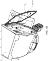
- Fig. 1A illustrates a schematic view of the cabin C of a large machine wherein the door D and the secondary support handle 101 or 201 according to the present invention are both in closed state
- Fig. 1B illustrates a schematic view of the cabin C of a large machine wherein the door D and the secondary support handle 101 or 201 according to the present invention are both in opened state.
- Fig. 2A and Fig. 3A illustrates a front view of the secondary support handle assembly 100 according to a first embodiment of the present invention.
- the secondary support handle assembly 100 comprises a secondary support handle 101 having a pair of vertical and horizontal holding structures 101V1, 101V2 and 101H1, 101H2 respectively as shown in Fig. 4A .
- the vertical holding structure 101V1 is for supporting an operator of the large machine during ingress/egress operation when the operator is inside the cabin and the vertical holding structure 101V2 is for supporting the operator during ingress/egress operation when the operator is on outside steps of the large machine.
- the horizontal holding structure 101H1 will help in closing of the door D of the large machine as it would be closer to the operator seat and will not require stretch of arms.
- the secondary support handle 101 is thus very ergonomic and it facilitates easy ingress/egress during all the positions of the operator and easy closing of the door after getting seated.
- the secondary support handle assembly 100 further comprises a pair of geared hinges 102 coupled with a pair of geared hinges 102D of the door D in such a way that the axes of rotation of the secondary support handle and the door AX1 and AX2 are connected to each other, thereby providing relative rotation for the secondary support handle and the door. That is, rotation of one is governed by the other for a given gear ratio. For example, when the gear ratio between the geared hinges of the door and the secondary support handle assembly is 1:2, then the secondary support handle 101 rotates half the rotation of the door D.
- Fig. 4A illustrates a schematic diagram of the secondary support handle attached to the geared hinges 102 and 102D.
- the secondary support handle 101 is attached to the geared hinges 102 of the secondary support handle assembly at both ends.
- Fig. 4B illustrates a schematic diagram of the geared hinges 102 and 102D showing the axes of rotation of the secondary support handle and the door AX1 and AX2 respectively.
- Fig. 4C illustrates a schematic diagram of the gears G1 and G2 of the geared hinges 102D and 102 respectively, when the gear ratio is 1:2.
- the secondary support handle assembly 100 further comprises a rotary joint 103 attached to the cabin C of the large machine about which the secondary support handle 101 rotates.
- the secondary support handle assembly 100 also comprises a plate 104 attached to the cabin C.
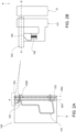
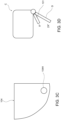
- the secondary support handle 101 is in contact with the plate 104 at one end through a telescopic tapered cylinder 105 and a spring 106 as shown in Fig. 2B and Fig. 3B .
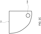
- the plate 104 is having a hole 104H at a location representing an angle of rotation x of the secondary support handle 101 in the direction of opening the secondary support handle 101 as shown in Fig. 2C and Fig. 3C .
- Fig. 2A the door D and the secondary support handle 101 are in closed state.
- Fig. 2B the spring 106 is in compressed state and the telescopic tapered cylinder 105 is in continuous contact with the plate 104 when the door D and the secondary support handle 101 are in closed state.
- Fig. 3A the door D and the secondary support handle 101 are in opened state.
- the secondary support handle 101 will also open due to coupling of their geared hinges 102D and 102 and while opening the secondary support handle 101, the telescopic tapered cylinder 105 rotates over the plate 104 in the direction of opening the secondary support handle and gets locked inside the hole 104H of the plate 104 at the said angle of rotation x of the secondary support handle 101 as shown in Fig. 3B and Fig. 3C .
- This self locking of the secondary support handle 101 helps to avoid any chances of slipping and vibrations when the operator holds the handle during ingress/egress.
- the said angle of rotation x of the secondary support handle 101 can be fixed as 45° at which the secondary support handle 101 can be locked since 45° is the most convenient angle for an operator to hold the secondary support handle 101 during ingress/egress operation.
- locking the secondary support handle 101 at an angle of rotation of 45° will enable the door to open up to 90° for a gear ratio of 1:2 as shown in Fig. 3D .
- the door D When closing the secondary support handle 101, the door D will also close due to coupling of their geared hinges 102D and 102 and while closing the secondary support handle 101, the telescopic tapered cylinder slides out of the hole 104H of the plate 104 by compressing the spring 106 and rotates over the plate 104 in the direction of closing the secondary support handle 101.
- fixing the angle as 45° at which the secondary support handle gets locked helps the operator to conveniently close the secondary support handle and thereby the door after getting seated.
- Fig. 5A and Fig. 6A illustrates a front view of the secondary support handle assembly 200 according to a second embodiment of the present invention.
- the secondary support handle assembly 200 comprises a secondary support handle 201.
- the shape of the secondary support handle 201 is similar to that of the secondary support handle 101 according to the first embodiment to have a pair of vertical and horizontal holding structures as shown in Fig. 4A .
- the secondary support handle assembly 200 further comprises a pair of torsional springs 202 connecting the secondary support handle 201 and the cabin C of the large machine.
- the torsional springs 202 are in stiffened state such that they have tendency to open the secondary support handle 201.
- the secondary support handle 201 is attached to the torsional springs 202 at both ends.
- the secondary support handle assembly 200 further comprises a rotary joint 203 attached to the cabin C of the large machine about which the secondary support handle 201 rotates.
- the secondary support handle assembly 200 also comprises a first plate 204 attached to the cabin C.
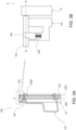
- the secondary support handle 201 is in contact with the first plate 204 at one end through a telescopic tapered cylinder 205 and a spring 206 as shown in Fig. 5B and Fig. 6B .
- the plate 204 is having a hole 204H at a location representing an angle of rotation x of the secondary support handle 201 in the direction of opening the secondary support handle 201 as shown in Fig. 5C and Fig. 6D .
- the door D and the secondary support handle 201 are in closed state.
- the spring 206 is in compressed state and the telescopic tapered cylinder 205 is in continuous contact with the plate 204 when the door D and the secondary support handle 201 are in closed state.
- the door D and the secondary support handle 201 are in opened state.
- the secondary support handle 201 will also open due to the stiffness of the torsional springs 202 and while opening the secondary support handle 201, the telescopic tapered cylinder 205 rotates over the plate 204 in the direction of opening the secondary support handle 201 and gets locked inside the hole 204H of the first plate 204 at the said angle of rotation x of the secondary support handle 201 as shown in Fig. 6B and Fig. 6D .
- This self locking of the secondary support handle 201 helps to avoid any chances of slipping and vibrations when the operator holds the handle during ingress/egress.
- the said angle of rotation of the secondary support handle 201 can be fixed as 45° at which the secondary support handle 201 can be locked since 45° is the most convenient angle for an operator to hold the secondary support handle 201 during ingress/egress operation.
- the telescopic tapered cylinder 205 slides out of the hole 204H of the first plate 204 by compressing the spring 206 and rotates over the first plate 204 in the direction of closing the secondary support handle 201.
- a second plate 207 attached to the door D and a push handle 208 attached to the secondary support handle 201 are provided.
- the second plate 207 is having a hole 207H such that the second plate 207 aligns parallelly above the first plate 204 and the respective holes 204H and 207H of the first and second plates 204 and 207 coincide with each other when the secondary support handle 201 is in the locked state.
- Fig. 6B the push handle 208 is in unpressed condition and in Fig. 6C , the push handle 208 is in pressed condition.
- Fig. 6E illustrates a schematic top view of Fig. 6A .
- exemplary embodiments of the present invention allow the operator of the large machine to conveniently perform the ingress/egress operation and easily close the door of the large machine after getting seated without requiring stretch of arms. It would result in the comfortable postures for the operator resulting in less fatigue. Exemplary embodiments formed in accordance with the present invention, therefore, can solve the safety issues related to ingress/egress in a cabin and to allow the operator to easily close the door.
- the ergonomic shape of the secondary support handle facilitates easy ingress/egress during all the positions of the operator.
- the horizontal structure of the secondary support handle will help in closing of the door easily as it would be closer to the operator seat and will not require stretch of arms.
- the secondary support handle assembly according to various embodiments of the present invention can be easily integrated with any existing door without any major modifications. Also, it self-actuates based on the main door rotation. Self-locking of the secondary support handle avoids any chances of slipping and vibrations. It is cost saving as multiple static handles provided on the door and the cabin to support ingress/egress operation and door closing/opening can be avoided. It also improves the aesthetics of the cabin, by reducing the number of parts.
Landscapes
- Engineering & Computer Science (AREA)
- Transportation (AREA)
- Mechanical Engineering (AREA)
- Lock And Its Accessories (AREA)
Abstract
Description
- The present invention generally relates to support handles for large machines. More particularly, the present invention relates to a self-actuating ergonomic secondary support handle assembly for large machines.
- Large machines deployed in agriculture industry or construction industry and large transportation vehicles such as trucks or buses are having the operator cabin at a certain height from the ground level. For ingress/egress operation to and from the operator cabin in such large machines, there are provided few steps and support handles. A primary support handle attached to the cabin gives support to one hand of the operator during ingress/egress operation. However, due to the absence of such a support handle on the door side of the cabin, the operator has no support for his other hand during ingress/egress operation and has to take support of seat or plastic parts (console) of the large machine. Currently, in order to get support for the other hand of the operator during ingress/egress operation, short static secondary support handles have been provided on multiple locations of the door side of the cabin, but the operator has to stretch or extend himself to grab such secondary support handles or any kind of support through which he can lift his body which is not just uncomfortable but can also be dangerous. While egress, it is difficult for the operator to have support for the other hand with the available secondary static support handles during the last few steps. Also, the clearance between handrail of the secondary static handles and adjacent parts is generally less considering the integration of different parts in the door side of the cabin. It could result in safety issues and awkward postures with undesired bending for the operator. Also, with the available secondary static handles, it would be difficult for short people to have 3-point contact (3 parts out of 2 hands and 2 feet) during ingress/egress operation.
- Also, after getting seated, the operator needs to have an extended reach to the door handle for closing of the door while sitting in the cabin and the operator must stand up from the seat to close the door.
- Therefore, there is a need for an improved secondary support handle for large machines which can overcome the above mentioned disadvantages of known secondary support handles and door handles.
- The present invention addresses the above mentioned problems, and provides a self-actuating ergonomic secondary support handle for large machines which solves the safety issues related to ingress/egress in a cabin by providing support for the operator in all his intermediate positions during ingress/egress operation and also acts as a door handle allowing the operator to easily close the door after getting seated.
- It is therefore an object of the present invention to provide a self-actuating ergonomic secondary support handle assembly to solve the safety issues related to ingress/egress in the cabin of a large machine and to allow the operator to easily close the door after getting seated. The secondary support handle is self-actuated based on the door rotation.
- It is a further object of the present invention to provide a secondary support handle assembly which can be self locked at a particular angle of rotation avoiding any chances of slipping and vibrations during ingress/egress operation.
- It is another object of the present invention to provide a secondary support handle assembly to avoid multiple static handles provided on the cabin and the door to support ingress/egress operation and door opening/closing.
- It is another object of the present invention to provide a secondary support handle assembly that can be integrated with any existing door without any major modifications.
- It is another object of the present invention to provide a secondary support handle assembly which supports all the intermediate positions of the operator during the ingress/egress operation.
- It is yet another object of the present invention to provide a cost saving secondary support handle assembly which is also improving the aesthetics of the cabin, by reducing the number of parts.
- The present invention provides a secondary support handle assembly for large machines as claimed in the appended set of claims, thereby solving the aforementioned objects.
- The above and other objects and features of the invention will become apparent from the following description of preferred embodiments taken in conjunction with the accompanying drawings, in which like reference numbers indicate like features.
-
Fig. 1A illustrates a schematic view of a cabin of a large machine wherein the door and the secondary support handle according to an embodiment of the present invention are both in closed state. -
Fig. 1B illustrates a schematic view of a cabin of a large machine wherein the door and the secondary support handle according to an embodiment of the present invention are both in opened state. -
Fig. 2A illustrates a front view of the secondary support handle assembly according to a first embodiment of the present invention when the door and the secondary support handle are in closed state. -
Fig. 2B illustrates an enhanced view of the portion P as shown inFig. 2A . -
Fig. 2C illustrates a sectional view taken along X-X and seen in a direction A as shown inFig. 2B . -
Fig. 3A illustrates a front view of the secondary support handle assembly according to the first embodiment of the present invention when the door and the secondary support handle are in opened state. -
Fig. 3B illustrates an enhanced view of the portion P as shown inFig. 3A . -
Fig. 3C illustrates a sectional view taken along X-X and seen in a direction A as shown inFig. 3B . -
Fig. 3D illustrates a schematic top view ofFig. 3A . -
Fig. 4A illustrates a schematic diagram of the secondary support handle attached to the geared hinges. -
Fig. 4B illustrates a schematic diagram of the geared hinges. -
Fig. 4C illustrates a schematic diagram of the gears of the geared hinges. -
Fig. 5A illustrates a front view of the secondary support handle assembly according to a second embodiment of the present invention when the door and the secondary support handle are in closed state. -
Fig. 5B illustrates an enhanced view of the portion P as shown inFig. 5A . -
Fig. 5C illustrates a sectional view taken along X-X and seen in a direction A as shown inFig. 5B . -
Fig. 6A illustrates a front view of the secondary support handle assembly according to the second embodiment of the present invention when the door and the secondary support handle are in opened state. -
Fig. 6B illustrates an enhanced view of the portion P as shown inFig. 6A when the push handle is in unpressed condition. -
Fig. 6C illustrates an enhanced view of the portion P as shown inFig. 6A when the push handle is in pressed condition. -
Fig. 6D illustrates a sectional view taken along X-X and seen in a direction A as shown inFig. 6B or Fig. 6C . -
Fig. 6E illustrates a schematic top view ofFig. 6A . - The preferred embodiments of the present invention will now be described more fully with reference to the accompanying drawings. The detailed description is not limiting the scope of the invention, which is defined only by the appended claims.
Fig. 1A illustrates a schematic view of the cabin C of a large machine wherein the door D and the secondary support handle 101 or 201 according to the present invention are both in closed state andFig. 1B illustrates a schematic view of the cabin C of a large machine wherein the door D and the secondary support handle 101 or 201 according to the present invention are both in opened state. -
Fig. 2A andFig. 3A illustrates a front view of the secondarysupport handle assembly 100 according to a first embodiment of the present invention. The secondarysupport handle assembly 100 comprises a secondary support handle 101 having a pair of vertical and horizontal holding structures 101V1, 101V2 and 101H1, 101H2 respectively as shown inFig. 4A . The vertical holding structure 101V1 is for supporting an operator of the large machine during ingress/egress operation when the operator is inside the cabin and the vertical holding structure 101V2 is for supporting the operator during ingress/egress operation when the operator is on outside steps of the large machine. The horizontal holding structure 101H1 will help in closing of the door D of the large machine as it would be closer to the operator seat and will not require stretch of arms. The secondary support handle 101 is thus very ergonomic and it facilitates easy ingress/egress during all the positions of the operator and easy closing of the door after getting seated. - The secondary
support handle assembly 100 further comprises a pair of geared hinges 102 coupled with a pair of geared hinges 102D of the door D in such a way that the axes of rotation of the secondary support handle and the door AX1 and AX2 are connected to each other, thereby providing relative rotation for the secondary support handle and the door. That is, rotation of one is governed by the other for a given gear ratio. For example, when the gear ratio between the geared hinges of the door and the secondary support handle assembly is 1:2, then the secondary support handle 101 rotates half the rotation of the door D.Fig. 4A illustrates a schematic diagram of the secondary support handle attached to the geared hinges 102 and 102D. The secondary support handle 101 is attached to the geared hinges 102 of the secondary support handle assembly at both ends.Fig. 4B illustrates a schematic diagram of the geared hinges 102 and 102D showing the axes of rotation of the secondary support handle and the door AX1 and AX2 respectively. Further,Fig. 4C illustrates a schematic diagram of the gears G1 and G2 of the geared hinges 102D and 102 respectively, when the gear ratio is 1:2. - The secondary
support handle assembly 100 further comprises a rotary joint 103 attached to the cabin C of the large machine about which the secondary support handle 101 rotates. - The secondary
support handle assembly 100 also comprises aplate 104 attached to the cabin C. The secondary support handle 101 is in contact with theplate 104 at one end through a telescopictapered cylinder 105 and aspring 106 as shown inFig. 2B andFig. 3B . Theplate 104 is having ahole 104H at a location representing an angle of rotation x of the secondary support handle 101 in the direction of opening the secondary support handle 101 as shown inFig. 2C andFig. 3C . - In
Fig. 2A , the door D and the secondary support handle 101 are in closed state. As shown inFig. 2B , thespring 106 is in compressed state and the telescopictapered cylinder 105 is in continuous contact with theplate 104 when the door D and the secondary support handle 101 are in closed state. - In
Fig. 3A , the door D and the secondary support handle 101 are in opened state. When opening the door D, the secondary support handle 101 will also open due to coupling of their geared hinges 102D and 102 and while opening thesecondary support handle 101, the telescopictapered cylinder 105 rotates over theplate 104 in the direction of opening the secondary support handle and gets locked inside thehole 104H of theplate 104 at the said angle of rotation x of the secondary support handle 101 as shown inFig. 3B andFig. 3C . This self locking of the secondary support handle 101 helps to avoid any chances of slipping and vibrations when the operator holds the handle during ingress/egress. For example, the said angle of rotation x of the secondary support handle 101 can be fixed as 45° at which the secondary support handle 101 can be locked since 45° is the most convenient angle for an operator to hold the secondary support handle 101 during ingress/egress operation. Also, locking the secondary support handle 101 at an angle of rotation of 45° will enable the door to open up to 90° for a gear ratio of 1:2 as shown inFig. 3D . When closing thesecondary support handle 101, the door D will also close due to coupling of their geared hinges 102D and 102 and while closing thesecondary support handle 101, the telescopic tapered cylinder slides out of thehole 104H of theplate 104 by compressing thespring 106 and rotates over theplate 104 in the direction of closing thesecondary support handle 101. Also, fixing the angle as 45° at which the secondary support handle gets locked helps the operator to conveniently close the secondary support handle and thereby the door after getting seated. -
Fig. 5A andFig. 6A illustrates a front view of the secondarysupport handle assembly 200 according to a second embodiment of the present invention. The secondarysupport handle assembly 200 comprises asecondary support handle 201. The shape of the secondary support handle 201 is similar to that of the secondary support handle 101 according to the first embodiment to have a pair of vertical and horizontal holding structures as shown inFig. 4A . - The secondary
support handle assembly 200 further comprises a pair oftorsional springs 202 connecting the secondary support handle 201 and the cabin C of the large machine. The torsional springs 202 are in stiffened state such that they have tendency to open thesecondary support handle 201. The secondary support handle 201 is attached to the torsional springs 202 at both ends. - The secondary
support handle assembly 200 further comprises a rotary joint 203 attached to the cabin C of the large machine about which the secondary support handle 201 rotates. - The secondary
support handle assembly 200 also comprises afirst plate 204 attached to the cabin C. The secondary support handle 201 is in contact with thefirst plate 204 at one end through a telescopictapered cylinder 205 and aspring 206 as shown inFig. 5B andFig. 6B . Theplate 204 is having ahole 204H at a location representing an angle of rotation x of the secondary support handle 201 in the direction of opening the secondary support handle 201 as shown inFig. 5C andFig. 6D . InFig. 5A , the door D and the secondary support handle 201 are in closed state. As shown inFig. 5B , thespring 206 is in compressed state and the telescopictapered cylinder 205 is in continuous contact with theplate 204 when the door D and the secondary support handle 201 are in closed state. - In
Fig. 6A , the door D and the secondary support handle 201 are in opened state. When opening the door D, the secondary support handle 201 will also open due to the stiffness of the torsional springs 202 and while opening thesecondary support handle 201, the telescopictapered cylinder 205 rotates over theplate 204 in the direction of opening the secondary support handle 201 and gets locked inside thehole 204H of thefirst plate 204 at the said angle of rotation x of the secondary support handle 201 as shown inFig. 6B andFig. 6D . This self locking of the secondary support handle 201 helps to avoid any chances of slipping and vibrations when the operator holds the handle during ingress/egress. For example, the said angle of rotation of the secondary support handle 201 can be fixed as 45° at which the secondary support handle 201 can be locked since 45° is the most convenient angle for an operator to hold the secondary support handle 201 during ingress/egress operation. - When closing the
secondary support handle 201, the telescopictapered cylinder 205 slides out of thehole 204H of thefirst plate 204 by compressing thespring 206 and rotates over thefirst plate 204 in the direction of closing thesecondary support handle 201. - In order to close the door D along with the
secondary support handle 201, asecond plate 207 attached to the door D and apush handle 208 attached to the secondary support handle 201 are provided. Thesecond plate 207 is having a hole 207H such that thesecond plate 207 aligns parallelly above thefirst plate 204 and therespective holes 204H and 207H of the first andsecond plates arm 209 attached to the telescopictapered cylinder 205 for rotating about afulcrum 210 such that the telescopictapered cylinder 205 further moves up by elongating thespring 206 and gets inserted in the hole 207H of thesecond plate 207, thereby closing the door D together with thesecondary support handle 201. InFig. 6B , the push handle 208 is in unpressed condition and inFig. 6C , the push handle 208 is in pressed condition.Fig. 6E illustrates a schematic top view ofFig. 6A . - It should thus be appreciated that exemplary embodiments of the present invention allow the operator of the large machine to conveniently perform the ingress/egress operation and easily close the door of the large machine after getting seated without requiring stretch of arms. It would result in the comfortable postures for the operator resulting in less fatigue. Exemplary embodiments formed in accordance with the present invention, therefore, can solve the safety issues related to ingress/egress in a cabin and to allow the operator to easily close the door.
- Therefore, through the present invention, operator convenience can be enhanced. The ergonomic shape of the secondary support handle facilitates easy ingress/egress during all the positions of the operator. Also, the horizontal structure of the secondary support handle will help in closing of the door easily as it would be closer to the operator seat and will not require stretch of arms. The secondary support handle assembly according to various embodiments of the present invention can be easily integrated with any existing door without any major modifications. Also, it self-actuates based on the main door rotation. Self-locking of the secondary support handle avoids any chances of slipping and vibrations. It is cost saving as multiple static handles provided on the door and the cabin to support ingress/egress operation and door closing/opening can be avoided. It also improves the aesthetics of the cabin, by reducing the number of parts.
- It is understood therefore that various embodiments not described here explicitly are within the scope of the appended claims.
Claims (10)
- A self-actuating ergonomic secondary support handle assembly (100) for large machines, the secondary support handle assembly (100) comprising:a secondary support handle (101);a pair of geared hinges (102) coupled with a pair of geared hinges (102D) of a door (D) of the large machine, the geared hinges of the secondary support handle assembly (102) and the geared hinges of the door (102D) connect axes of rotation (AX1, AX2) of the secondary support handle and the door, thereby providing relative rotation for the secondary support handle (101) and the door (D);a rotary joint (103) attached to cabin (C) of the large machine about which the secondary support handle (101) rotates; anda plate (104) attached to the cabin (C);wherein,the secondary support handle (101) is attached to the geared hinges (102) of the secondary support handle assembly (100) at both ends and is in contact with the plate (104) at one end,the secondary support handle (101) is in contact with the plate (104) through a telescopic tapered cylinder (105) and a spring (106), the spring (106) being in compressed state and the telescopic tapered cylinder (105) being in continuous contact with the plate (104) when the door (D) and the secondary support handle (101) are in closed state,the plate (104) is having a hole (104H) at a location representing an angle of rotation (x) of the secondary support handle (101) in a direction of opening the secondary support handle (101),when opening the door (D), the secondary support handle (101) opens due to coupling of the geared hinges (102, 102D), the telescopic tapered cylinder (105) rotates over the plate (104) in the direction of opening the secondary support handle (101) and gets locked inside the hole (104H) of the plate (104) at the said angle of rotation (x) of the secondary support handle (101), andwhen closing the secondary support handle (101), the door (D) closes due to coupling of the geared hinges, the telescopic tapered cylinder (105) slides out of the hole (104H) of the plate (104) by compressing the spring (106) and rotates over the plate (104) in the direction of closing the secondary support handle (101).
- The secondary support handle assembly (100) according to claim 1, wherein the secondary support handle (101) comprises a pair of vertical and horizontal holding structures (101V1, 101V2; 101H1, 101H2).
- The secondary support handle assembly (100) according to claims 1 or 2, wherein a gear ratio between the geared hinges (102, 102D) of the door and the secondary support handle assembly is 1:2 such that the secondary support handle (101) rotates half the rotation of the door (D).
- The secondary support handle assembly (100) according to any one of the preceding claims, wherein the angle of rotation (x) of the secondary support handle (101) is 45°.
- A self-actuating ergonomic secondary support handle assembly (200) for large machines, the secondary support handle assembly (200) comprising:a secondary support handle (201);a pair of torsional springs (202) connecting the secondary support handle (201) and cabin (C) of the large machine, the torsional springs (202) are in stiffened state such that they have tendency to open the secondary support handle (201);a rotary joint (203) attached to the cabin (C) about which the secondary support handle (201) rotates; anda first plate (204) attached to the cabin (C);wherein,the secondary support handle (201) is attached to the torsional springs (202) at both ends and is in contact with the first plate (204) at one end,the secondary support handle (201) is in contact with the first plate (204) through a telescopic tapered cylinder (205) and a spring (206), the spring (206) being in compressed state and the telescopic tapered cylinder (205) being in continuous contact with the first plate (204) when a door (D) of the large machine and the secondary support handle (201) are in closed state,the first plate (204) incudes a hole (204H) at a location representing an angle of rotation (x) of the secondary support handle (201) in a direction of opening the secondary support handle (201),when opening the door (D), the secondary support handle (201) opens due to the stiffness of the torsional springs (202), the telescopic tapered cylinder (205) rotates over the first plate (204) in the direction of opening the secondary support handle (201) and gets locked inside the hole (204H) of the first plate (204) at the angle of rotation (x) of the secondary support handle (201),when closing the secondary support handle (201), the telescopic tapered cylinder (205) slides out of the hole (204H) of the first plate (204) by compressing the spring (206) and rotates over the first plate (204) in the direction of closing the secondary support handle (201).
- The secondary support handle assembly (200) according to claim 5, wherein the secondary support handle (201) comprises a pair of vertical and horizontal holding structures.
- The secondary support handle assembly (200) according to claims 5 or 6, wherein the angle of rotation (x) of the secondary support handle (201) is 45°.
- The secondary support handle assembly (200) according to any one of the preceding claims, wherein a second plate (207) comprises a hole (207H) is attached to the door (D) such that the second plate (207) aligns parallelly above the first plate (204) and the respective holes (204H, 207H) of the first and second plates (204, 207) coincide with each other when the secondary support handle (201) is in the locked state.
- The secondary support handle assembly (200) according to any one of the preceding claims, further comprises a push handle (208) attached to the secondary support handle (201), wherein pressing the push handle (208) while closing the secondary support handle (201) actuates an arm (209) attached to the telescopic tapered cylinder (205) for rotating about a fulcrum (210) such that the telescopic tapered cylinder (205) moves up by elongating the spring (206) and gets inserted in the hole (207H) of the second plate (207), thereby closing the door (D) together with the secondary support handle (201).
- A large machine comprising a secondary support assembly in accordance with any one of the preceding claims.
Applications Claiming Priority (1)
| Application Number | Priority Date | Filing Date | Title |
|---|---|---|---|
| IT102023000014886A IT202300014886A1 (en) | 2023-07-17 | 2023-07-17 | SELF-ACTUATING AND ERGONOMIC SECONDARY SUPPORT HANDLE ASSEMBLY FOR LARGE MACHINES |
Publications (2)
| Publication Number | Publication Date |
|---|---|
| EP4509356A1 true EP4509356A1 (en) | 2025-02-19 |
| EP4509356B1 EP4509356B1 (en) | 2026-03-25 |
Family
ID=88097934
Family Applications (1)
| Application Number | Title | Priority Date | Filing Date |
|---|---|---|---|
| EP24189057.3A Active EP4509356B1 (en) | 2023-07-17 | 2024-07-17 | Self-actuating ergonomic secondary support handle assembly for large machines |
Country Status (2)
| Country | Link |
|---|---|
| EP (1) | EP4509356B1 (en) |
| IT (1) | IT202300014886A1 (en) |
Citations (6)
| Publication number | Priority date | Publication date | Assignee | Title |
|---|---|---|---|---|
| US3747273A (en) * | 1972-03-20 | 1973-07-24 | Year A Round Cab Corp | Door closure structure |
| US4957324A (en) * | 1989-07-13 | 1990-09-18 | J.I. Case Company | Combination guide rail door handle |
| DE202008004706U1 (en) * | 2008-04-09 | 2008-06-26 | Daimler Ag | Entry and exit aid for an entrance door of a bus |
| CN112937265A (en) * | 2019-12-10 | 2021-06-11 | 海斯特-耶鲁集团有限公司 | Lift loading and unloading car driver cabin door |
| US11420689B2 (en) * | 2019-02-07 | 2022-08-23 | Hamm Ag | Soil processing machine |
| EP3947036B1 (en) * | 2019-03-12 | 2023-06-07 | Volvo Truck Corporation | Retractable handrail arrangement |
-
2023
- 2023-07-17 IT IT102023000014886A patent/IT202300014886A1/en unknown
-
2024
- 2024-07-17 EP EP24189057.3A patent/EP4509356B1/en active Active
Patent Citations (6)
| Publication number | Priority date | Publication date | Assignee | Title |
|---|---|---|---|---|
| US3747273A (en) * | 1972-03-20 | 1973-07-24 | Year A Round Cab Corp | Door closure structure |
| US4957324A (en) * | 1989-07-13 | 1990-09-18 | J.I. Case Company | Combination guide rail door handle |
| DE202008004706U1 (en) * | 2008-04-09 | 2008-06-26 | Daimler Ag | Entry and exit aid for an entrance door of a bus |
| US11420689B2 (en) * | 2019-02-07 | 2022-08-23 | Hamm Ag | Soil processing machine |
| EP3947036B1 (en) * | 2019-03-12 | 2023-06-07 | Volvo Truck Corporation | Retractable handrail arrangement |
| CN112937265A (en) * | 2019-12-10 | 2021-06-11 | 海斯特-耶鲁集团有限公司 | Lift loading and unloading car driver cabin door |
Also Published As
| Publication number | Publication date |
|---|---|
| EP4509356B1 (en) | 2026-03-25 |
| IT202300014886A1 (en) | 2025-01-17 |
Similar Documents
| Publication | Publication Date | Title |
|---|---|---|
| US7676868B2 (en) | Birthing bed foot support release handle | |
| US6012548A (en) | Ladder frame | |
| CN107429532B (en) | Support device for a furniture flap and furniture having a support device | |
| US7608028B2 (en) | Exercise equipment with multi-positioning handles | |
| EP3132710A1 (en) | Lift table for computer | |
| EP4509356B1 (en) | Self-actuating ergonomic secondary support handle assembly for large machines | |
| JPH08182567A (en) | Seat frame assembly for automobile and method for manufacturing seat frame assembly | |
| US5664290A (en) | Hinge device for swivel holding of a leaf flap | |
| US20110148167A1 (en) | Passenger seat assembly | |
| EP2864153B1 (en) | Vehicle seat having a floor position | |
| US11014473B2 (en) | Adjustable height limiter | |
| US20220298833A1 (en) | External opening control with multi-articulated pallet | |
| CN113490613A (en) | Telescopic armrest device | |
| US20060267390A1 (en) | Arrangement for a seat for an automobile vehicle to limit its overall lengthwise size | |
| US20250170928A1 (en) | Seating assembly with displaceable panel | |
| JP4423480B2 (en) | Walking assistance vehicle | |
| US5730689A (en) | Articulating pull handle | |
| SE543523C2 (en) | A coupler comprising a handle and a handle therefor | |
| US9446699B2 (en) | Footrest for construction machine operating room | |
| EP3774632B1 (en) | Improvements in or relating to folding chairs | |
| US6170355B1 (en) | Ergonomic range accommodating adjustable foot pedal | |
| KR102153502B1 (en) | washbasin aid device with the upper body support and washbasin with the aid device | |
| US20190291622A1 (en) | Shield assembly for a dump box | |
| DE202009013840U1 (en) | Handle device | |
| KR200268848Y1 (en) | Consolidation structure of belt-line cover for partition |
Legal Events
| Date | Code | Title | Description |
|---|---|---|---|
| PUAI | Public reference made under article 153(3) epc to a published international application that has entered the european phase |
Free format text: ORIGINAL CODE: 0009012 |
|
| STAA | Information on the status of an ep patent application or granted ep patent |
Free format text: STATUS: THE APPLICATION HAS BEEN PUBLISHED |
|
| AK | Designated contracting states |
Kind code of ref document: A1 Designated state(s): AL AT BE BG CH CY CZ DE DK EE ES FI FR GB GR HR HU IE IS IT LI LT LU LV MC ME MK MT NL NO PL PT RO RS SE SI SK SM TR |
|
| STAA | Information on the status of an ep patent application or granted ep patent |
Free format text: STATUS: REQUEST FOR EXAMINATION WAS MADE |
|
| 17P | Request for examination filed |
Effective date: 20250819 |
|
| GRAP | Despatch of communication of intention to grant a patent |
Free format text: ORIGINAL CODE: EPIDOSNIGR1 |
|
| STAA | Information on the status of an ep patent application or granted ep patent |
Free format text: STATUS: GRANT OF PATENT IS INTENDED |
|
| INTG | Intention to grant announced |
Effective date: 20251030 |
|
| GRAS | Grant fee paid |
Free format text: ORIGINAL CODE: EPIDOSNIGR3 |
|
| GRAA | (expected) grant |
Free format text: ORIGINAL CODE: 0009210 |
|
| STAA | Information on the status of an ep patent application or granted ep patent |
Free format text: STATUS: THE PATENT HAS BEEN GRANTED |
|
| AK | Designated contracting states |
Kind code of ref document: B1 Designated state(s): AL AT BE BG CH CY CZ DE DK EE ES FI FR GB GR HR HU IE IS IT LI LT LU LV MC ME MK MT NL NO PL PT RO RS SE SI SK SM TR |
|
| REG | Reference to a national code |
Ref country code: CH Ref legal event code: F10 Free format text: ST27 STATUS EVENT CODE: U-0-0-F10-F00 (AS PROVIDED BY THE NATIONAL OFFICE) Effective date: 20260325 Ref country code: GB Ref legal event code: FG4D |
|
| REG | Reference to a national code |
Ref country code: DE Ref legal event code: R096 Ref document number: 602024003404 Country of ref document: DE |
|
| REG | Reference to a national code |
Ref country code: IE Ref legal event code: FG4D |
|
| PG25 | Lapsed in a contracting state [announced via postgrant information from national office to epo] |
Ref country code: RS Free format text: LAPSE BECAUSE OF FAILURE TO SUBMIT A TRANSLATION OF THE DESCRIPTION OR TO PAY THE FEE WITHIN THE PRESCRIBED TIME-LIMIT Effective date: 20260625 |
|
| PG25 | Lapsed in a contracting state [announced via postgrant information from national office to epo] |
Ref country code: GR Free format text: LAPSE BECAUSE OF FAILURE TO SUBMIT A TRANSLATION OF THE DESCRIPTION OR TO PAY THE FEE WITHIN THE PRESCRIBED TIME-LIMIT Effective date: 20260626 |
|
| REG | Reference to a national code |
Ref country code: LT Ref legal event code: MG9D |
|
| PG25 | Lapsed in a contracting state [announced via postgrant information from national office to epo] |
Ref country code: LT Free format text: LAPSE BECAUSE OF FAILURE TO SUBMIT A TRANSLATION OF THE DESCRIPTION OR TO PAY THE FEE WITHIN THE PRESCRIBED TIME-LIMIT Effective date: 20260325 |
|
| PG25 | Lapsed in a contracting state [announced via postgrant information from national office to epo] |
Ref country code: NO Free format text: LAPSE BECAUSE OF FAILURE TO SUBMIT A TRANSLATION OF THE DESCRIPTION OR TO PAY THE FEE WITHIN THE PRESCRIBED TIME-LIMIT Effective date: 20260625 |
|
| PG25 | Lapsed in a contracting state [announced via postgrant information from national office to epo] |
Ref country code: FI Free format text: LAPSE BECAUSE OF FAILURE TO SUBMIT A TRANSLATION OF THE DESCRIPTION OR TO PAY THE FEE WITHIN THE PRESCRIBED TIME-LIMIT Effective date: 20260325 Ref country code: SE Free format text: LAPSE BECAUSE OF FAILURE TO SUBMIT A TRANSLATION OF THE DESCRIPTION OR TO PAY THE FEE WITHIN THE PRESCRIBED TIME-LIMIT Effective date: 20260325 |
|
| PG25 | Lapsed in a contracting state [announced via postgrant information from national office to epo] |
Ref country code: HR Free format text: LAPSE BECAUSE OF FAILURE TO SUBMIT A TRANSLATION OF THE DESCRIPTION OR TO PAY THE FEE WITHIN THE PRESCRIBED TIME-LIMIT Effective date: 20260325 |
|
| PG25 | Lapsed in a contracting state [announced via postgrant information from national office to epo] |
Ref country code: LV Free format text: LAPSE BECAUSE OF FAILURE TO SUBMIT A TRANSLATION OF THE DESCRIPTION OR TO PAY THE FEE WITHIN THE PRESCRIBED TIME-LIMIT Effective date: 20260325 |
|
| PG25 | Lapsed in a contracting state [announced via postgrant information from national office to epo] |
Ref country code: BG Free format text: LAPSE BECAUSE OF FAILURE TO SUBMIT A TRANSLATION OF THE DESCRIPTION OR TO PAY THE FEE WITHIN THE PRESCRIBED TIME-LIMIT Effective date: 20260325 |
|
| REG | Reference to a national code |
Ref country code: NL Ref legal event code: MP Effective date: 20260325 |