EP4509350A1 - Battery charging control method and apparatus, devices, and storage medium - Google Patents
Battery charging control method and apparatus, devices, and storage medium Download PDFInfo
- Publication number
- EP4509350A1 EP4509350A1 EP23794863.3A EP23794863A EP4509350A1 EP 4509350 A1 EP4509350 A1 EP 4509350A1 EP 23794863 A EP23794863 A EP 23794863A EP 4509350 A1 EP4509350 A1 EP 4509350A1
- Authority
- EP
- European Patent Office
- Prior art keywords
- battery
- charging
- heating state
- state
- charging device
- Prior art date
- Legal status (The legal status is an assumption and is not a legal conclusion. Google has not performed a legal analysis and makes no representation as to the accuracy of the status listed.)
- Pending
Links
Images
Classifications
-
- B—PERFORMING OPERATIONS; TRANSPORTING
- B60—VEHICLES IN GENERAL
- B60L—PROPULSION OF ELECTRICALLY-PROPELLED VEHICLES; SUPPLYING ELECTRIC POWER FOR AUXILIARY EQUIPMENT OF ELECTRICALLY-PROPELLED VEHICLES; ELECTRODYNAMIC BRAKE SYSTEMS FOR VEHICLES IN GENERAL; MAGNETIC SUSPENSION OR LEVITATION FOR VEHICLES; MONITORING OPERATING VARIABLES OF ELECTRICALLY-PROPELLED VEHICLES; ELECTRIC SAFETY DEVICES FOR ELECTRICALLY-PROPELLED VEHICLES
- B60L53/00—Methods of charging batteries, specially adapted for electric vehicles; Charging stations or on-board charging equipment therefor; Exchange of energy storage elements in electric vehicles
- B60L53/60—Monitoring or controlling charging stations
-
- H—ELECTRICITY
- H02—GENERATION; CONVERSION OR DISTRIBUTION OF ELECTRIC POWER
- H02J—ELECTRIC POWER NETWORKS; CIRCUIT ARRANGEMENTS OR SYSTEMS FOR SUPPLYING OR DISTRIBUTING ELECTRIC POWER; SYSTEMS FOR STORING ELECTRIC ENERGY
- H02J7/00—Circuit arrangements for charging or discharging batteries or for supplying loads from batteries
- H02J7/90—Regulation of charging or discharging current or voltage
- H02J7/971—Regulation of charging or discharging current or voltage the charge cycle being controlled or terminated in response to non-electric parameters
- H02J7/975—Regulation of charging or discharging current or voltage the charge cycle being controlled or terminated in response to non-electric parameters in response to temperature
- H02J7/977—Regulation of charging or discharging current or voltage the charge cycle being controlled or terminated in response to non-electric parameters in response to temperature of the battery
-
- B—PERFORMING OPERATIONS; TRANSPORTING
- B60—VEHICLES IN GENERAL
- B60L—PROPULSION OF ELECTRICALLY-PROPELLED VEHICLES; SUPPLYING ELECTRIC POWER FOR AUXILIARY EQUIPMENT OF ELECTRICALLY-PROPELLED VEHICLES; ELECTRODYNAMIC BRAKE SYSTEMS FOR VEHICLES IN GENERAL; MAGNETIC SUSPENSION OR LEVITATION FOR VEHICLES; MONITORING OPERATING VARIABLES OF ELECTRICALLY-PROPELLED VEHICLES; ELECTRIC SAFETY DEVICES FOR ELECTRICALLY-PROPELLED VEHICLES
- B60L53/00—Methods of charging batteries, specially adapted for electric vehicles; Charging stations or on-board charging equipment therefor; Exchange of energy storage elements in electric vehicles
- B60L53/60—Monitoring or controlling charging stations
- B60L53/62—Monitoring or controlling charging stations in response to charging parameters, e.g. current, voltage or electrical charge
-
- B—PERFORMING OPERATIONS; TRANSPORTING
- B60—VEHICLES IN GENERAL
- B60L—PROPULSION OF ELECTRICALLY-PROPELLED VEHICLES; SUPPLYING ELECTRIC POWER FOR AUXILIARY EQUIPMENT OF ELECTRICALLY-PROPELLED VEHICLES; ELECTRODYNAMIC BRAKE SYSTEMS FOR VEHICLES IN GENERAL; MAGNETIC SUSPENSION OR LEVITATION FOR VEHICLES; MONITORING OPERATING VARIABLES OF ELECTRICALLY-PROPELLED VEHICLES; ELECTRIC SAFETY DEVICES FOR ELECTRICALLY-PROPELLED VEHICLES
- B60L53/00—Methods of charging batteries, specially adapted for electric vehicles; Charging stations or on-board charging equipment therefor; Exchange of energy storage elements in electric vehicles
- B60L53/60—Monitoring or controlling charging stations
- B60L53/65—Monitoring or controlling charging stations involving identification of vehicles or their battery types
-
- B—PERFORMING OPERATIONS; TRANSPORTING
- B60—VEHICLES IN GENERAL
- B60L—PROPULSION OF ELECTRICALLY-PROPELLED VEHICLES; SUPPLYING ELECTRIC POWER FOR AUXILIARY EQUIPMENT OF ELECTRICALLY-PROPELLED VEHICLES; ELECTRODYNAMIC BRAKE SYSTEMS FOR VEHICLES IN GENERAL; MAGNETIC SUSPENSION OR LEVITATION FOR VEHICLES; MONITORING OPERATING VARIABLES OF ELECTRICALLY-PROPELLED VEHICLES; ELECTRIC SAFETY DEVICES FOR ELECTRICALLY-PROPELLED VEHICLES
- B60L53/00—Methods of charging batteries, specially adapted for electric vehicles; Charging stations or on-board charging equipment therefor; Exchange of energy storage elements in electric vehicles
- B60L53/60—Monitoring or controlling charging stations
- B60L53/66—Data transfer between charging stations and vehicles
-
- B—PERFORMING OPERATIONS; TRANSPORTING
- B60—VEHICLES IN GENERAL
- B60L—PROPULSION OF ELECTRICALLY-PROPELLED VEHICLES; SUPPLYING ELECTRIC POWER FOR AUXILIARY EQUIPMENT OF ELECTRICALLY-PROPELLED VEHICLES; ELECTRODYNAMIC BRAKE SYSTEMS FOR VEHICLES IN GENERAL; MAGNETIC SUSPENSION OR LEVITATION FOR VEHICLES; MONITORING OPERATING VARIABLES OF ELECTRICALLY-PROPELLED VEHICLES; ELECTRIC SAFETY DEVICES FOR ELECTRICALLY-PROPELLED VEHICLES
- B60L58/00—Methods or circuit arrangements for monitoring or controlling batteries or fuel cells, specially adapted for electric vehicles
- B60L58/10—Methods or circuit arrangements for monitoring or controlling batteries or fuel cells, specially adapted for electric vehicles for monitoring or controlling batteries
- B60L58/24—Methods or circuit arrangements for monitoring or controlling batteries or fuel cells, specially adapted for electric vehicles for monitoring or controlling batteries for controlling the temperature of batteries
- B60L58/27—Methods or circuit arrangements for monitoring or controlling batteries or fuel cells, specially adapted for electric vehicles for monitoring or controlling batteries for controlling the temperature of batteries by heating
-
- H—ELECTRICITY
- H01—ELECTRIC ELEMENTS
- H01M—PROCESSES OR MEANS, e.g. BATTERIES, FOR THE DIRECT CONVERSION OF CHEMICAL ENERGY INTO ELECTRICAL ENERGY
- H01M10/00—Secondary cells; Manufacture thereof
- H01M10/42—Methods or arrangements for servicing or maintenance of secondary cells or secondary half-cells
- H01M10/44—Methods for charging or discharging
- H01M10/443—Methods for charging or discharging in response to temperature
-
- H—ELECTRICITY
- H01—ELECTRIC ELEMENTS
- H01M—PROCESSES OR MEANS, e.g. BATTERIES, FOR THE DIRECT CONVERSION OF CHEMICAL ENERGY INTO ELECTRICAL ENERGY
- H01M10/00—Secondary cells; Manufacture thereof
- H01M10/60—Heating or cooling; Temperature control
- H01M10/61—Types of temperature control
- H01M10/615—Heating or keeping warm
-
- H—ELECTRICITY
- H02—GENERATION; CONVERSION OR DISTRIBUTION OF ELECTRIC POWER
- H02J—ELECTRIC POWER NETWORKS; CIRCUIT ARRANGEMENTS OR SYSTEMS FOR SUPPLYING OR DISTRIBUTING ELECTRIC POWER; SYSTEMS FOR STORING ELECTRIC ENERGY
- H02J7/00—Circuit arrangements for charging or discharging batteries or for supplying loads from batteries
- H02J7/40—Circuit arrangements for charging or discharging batteries or for supplying loads from batteries characterised by the exchange of charge or discharge related data
- H02J7/42—Circuit arrangements for charging or discharging batteries or for supplying loads from batteries characterised by the exchange of charge or discharge related data with electronic devices having internal batteries, e.g. mobile phones
-
- H—ELECTRICITY
- H02—GENERATION; CONVERSION OR DISTRIBUTION OF ELECTRIC POWER
- H02J—ELECTRIC POWER NETWORKS; CIRCUIT ARRANGEMENTS OR SYSTEMS FOR SUPPLYING OR DISTRIBUTING ELECTRIC POWER; SYSTEMS FOR STORING ELECTRIC ENERGY
- H02J7/00—Circuit arrangements for charging or discharging batteries or for supplying loads from batteries
- H02J7/60—Circuit arrangements for charging or discharging batteries or for supplying loads from batteries including safety or protection arrangements
- H02J7/65—Circuit arrangements for charging or discharging batteries or for supplying loads from batteries including safety or protection arrangements against overtemperature
-
- H—ELECTRICITY
- H02—GENERATION; CONVERSION OR DISTRIBUTION OF ELECTRIC POWER
- H02J—ELECTRIC POWER NETWORKS; CIRCUIT ARRANGEMENTS OR SYSTEMS FOR SUPPLYING OR DISTRIBUTING ELECTRIC POWER; SYSTEMS FOR STORING ELECTRIC ENERGY
- H02J7/00—Circuit arrangements for charging or discharging batteries or for supplying loads from batteries
- H02J7/90—Regulation of charging or discharging current or voltage
- H02J7/927—Regulation of charging or discharging current or voltage with introduction of pulses during the charging process
-
- B—PERFORMING OPERATIONS; TRANSPORTING
- B60—VEHICLES IN GENERAL
- B60L—PROPULSION OF ELECTRICALLY-PROPELLED VEHICLES; SUPPLYING ELECTRIC POWER FOR AUXILIARY EQUIPMENT OF ELECTRICALLY-PROPELLED VEHICLES; ELECTRODYNAMIC BRAKE SYSTEMS FOR VEHICLES IN GENERAL; MAGNETIC SUSPENSION OR LEVITATION FOR VEHICLES; MONITORING OPERATING VARIABLES OF ELECTRICALLY-PROPELLED VEHICLES; ELECTRIC SAFETY DEVICES FOR ELECTRICALLY-PROPELLED VEHICLES
- B60L2240/00—Control parameters of input or output; Target parameters
- B60L2240/40—Drive Train control parameters
- B60L2240/54—Drive Train control parameters related to batteries
- B60L2240/545—Temperature
-
- B—PERFORMING OPERATIONS; TRANSPORTING
- B60—VEHICLES IN GENERAL
- B60L—PROPULSION OF ELECTRICALLY-PROPELLED VEHICLES; SUPPLYING ELECTRIC POWER FOR AUXILIARY EQUIPMENT OF ELECTRICALLY-PROPELLED VEHICLES; ELECTRODYNAMIC BRAKE SYSTEMS FOR VEHICLES IN GENERAL; MAGNETIC SUSPENSION OR LEVITATION FOR VEHICLES; MONITORING OPERATING VARIABLES OF ELECTRICALLY-PROPELLED VEHICLES; ELECTRIC SAFETY DEVICES FOR ELECTRICALLY-PROPELLED VEHICLES
- B60L2240/00—Control parameters of input or output; Target parameters
- B60L2240/60—Navigation input
- B60L2240/66—Ambient conditions
- B60L2240/662—Temperature
-
- B—PERFORMING OPERATIONS; TRANSPORTING
- B60—VEHICLES IN GENERAL
- B60L—PROPULSION OF ELECTRICALLY-PROPELLED VEHICLES; SUPPLYING ELECTRIC POWER FOR AUXILIARY EQUIPMENT OF ELECTRICALLY-PROPELLED VEHICLES; ELECTRODYNAMIC BRAKE SYSTEMS FOR VEHICLES IN GENERAL; MAGNETIC SUSPENSION OR LEVITATION FOR VEHICLES; MONITORING OPERATING VARIABLES OF ELECTRICALLY-PROPELLED VEHICLES; ELECTRIC SAFETY DEVICES FOR ELECTRICALLY-PROPELLED VEHICLES
- B60L58/00—Methods or circuit arrangements for monitoring or controlling batteries or fuel cells, specially adapted for electric vehicles
- B60L58/10—Methods or circuit arrangements for monitoring or controlling batteries or fuel cells, specially adapted for electric vehicles for monitoring or controlling batteries
- B60L58/24—Methods or circuit arrangements for monitoring or controlling batteries or fuel cells, specially adapted for electric vehicles for monitoring or controlling batteries for controlling the temperature of batteries
-
- Y—GENERAL TAGGING OF NEW TECHNOLOGICAL DEVELOPMENTS; GENERAL TAGGING OF CROSS-SECTIONAL TECHNOLOGIES SPANNING OVER SEVERAL SECTIONS OF THE IPC; TECHNICAL SUBJECTS COVERED BY FORMER USPC CROSS-REFERENCE ART COLLECTIONS [XRACs] AND DIGESTS
- Y02—TECHNOLOGIES OR APPLICATIONS FOR MITIGATION OR ADAPTATION AGAINST CLIMATE CHANGE
- Y02E—REDUCTION OF GREENHOUSE GAS [GHG] EMISSIONS, RELATED TO ENERGY GENERATION, TRANSMISSION OR DISTRIBUTION
- Y02E60/00—Enabling technologies; Technologies with a potential or indirect contribution to GHG emissions mitigation
- Y02E60/10—Energy storage using batteries
Definitions
- the present application relates to the technical field of batteries, and in particular to a battery charging control method and apparatus, an electronic device, a charging device, and a storage medium.
- Intellectualization and electrification are one of the important development directions in the field of intelligent transportation. Especially in the field of electrification, with the advancement of materials and technology, the energy density of battery packs is getting higher and higher, and vehicles are also using various types of battery packs as energy sources. Compared with traditional vehicles that mainly use fossil fuels as energy sources, modem vehicles are increasingly using battery packs represented by lithium-ion power batteries as energy sources.
- the present application provides a battery charging control method and apparatus, an electrical device, a charging device, and a storage medium, which can avoid possible damage caused by charging a power battery in a low-temperature environment.
- the present application provides a battery charging control method used for an electrical device, including:
- the electrical device and the charging device are connected physically, and various pre-charging preparation stages need to be completed before the charging device outputs power.
- the electrical device acquires a battery heating state and sends a first message carrying the battery heating state to the charging device.
- the charging device judges whether to enter the battery charging stage, i.e., whether to output power, according to the battery heating state.
- the electrical device can autonomously implement a process of pulse heating followed by direct current (DC) charging by relying on the interaction with the charging device, thereby avoiding possible damage to the power battery caused by charging in a low-temperature environment. A user does not need to wait for the battery to complete self-heating before connecting the charging device for charging, thereby improving the experience of the user.
- DC direct current
- the method before the acquiring a battery heating state, the method further includes:
- the electrical device before acquiring the battery heating state, can judge whether the battery heating state is a heating state or a heating completion state according to the current temperature of the power battery, so that the electrical device can quickly acquire the battery heating state, thereby improving the efficiency of the electrical device in completing subsequent processes.
- the method further includes:
- the ambient temperature may continue to change, and thus the battery temperature also changes accordingly, which may cause that the electrical device is still charging when the battery temperature decreases. It may cause damage to the battery.
- the electrical device after entering the battery charging stage, the electrical device continues to acquire the temperature of the battery.
- a charging stop instruction is sent to the charging device to stop charging of the battery, thereby avoiding damage to the battery.
- the low-temperature pulse heating stage can be started again to heat the battery.
- the electrical device after entering the battery charging stage, continues to acquire the current temperature of the battery, including: continuing to acquire the current temperature of the battery by the electrical device after entering the battery charging stage and a preset time has passed.
- the charging device judges whether to continue the charging of the battery according to the battery heating state, thereby achieving precise control of the battery charging.
- the sending a first message carrying the battery heating state to a charging device includes: sending the first message carrying the battery heating state to the charging device according to a first preset period.
- the electrical device periodically acquires the battery heating state, and sends the first message carrying the battery heating state to the charging device, so that the charging device can periodically acquire the battery heating state, thereby achieving precise control of battery charging.
- the method further includes: receiving a second message sent by the charging device, the second message carrying a state of the charging device.
- the electrical device after receiving the second message sent by the charging device, the electrical device can acquire the state of the charging device from the second message, so that normal communication is maintained between the electrical device and the charging device, thereby avoiding inconvenience caused to the user by interruption of the charging procedure.
- the method further includes: adding a corresponding sending time tag to the first message and then storing the first message added with the corresponding sending time tag.
- the electrical device adds a corresponding sending time tag to the first message sent to the charging device and stores the first message added with the corresponding sending time tag for the user to view, thereby improving the experience of the user.
- the present application provides a battery charging control method used for a charging device, including:
- the electrical device and the charging device are connected physically, and various pre-charging preparation stages need to be completed before the charging device outputs power.
- the electrical device acquires a battery heating state and sends a first message carrying the battery heating state to the charging device.
- the charging device judges whether to enter the battery charging stage, i.e., whether to output power, according to the battery heating state.
- the charging device can autonomously implement a process of pulse heating followed by direct current (DC) charging by relying on the interaction with the electrical device, thereby avoiding possible damage to the power battery caused by charging in a low-temperature environment, thereby improving the experience of the user.
- DC direct current
- the judging whether to enter a battery charging stage according to the battery heating state includes:
- the charging device when the battery is being heated, the charging device does not enter the battery charging stage, that is, the charging device does not output power, which can avoid possible damage to the power battery caused by charging in a low-temperature environment.
- the method further includes: sending a second message to the electrical device when the battery heating state is the heating state, the second message carrying a state of the charging device.
- the charging device when the battery is in the heating state, the charging device cannot charge the battery. In order to maintain the normal communication with the electrical device, the charging device sends the second message to the electrical device, so that the electrical device can know the current state of the charging device, thereby avoiding inconvenience to the user caused by interruption of the charging procedure.
- the sending a second message to the electrical device when the battery heating state is the heating state includes: sending the second message to the electrical device according to a second preset period when the battery heating state is the heating state.
- the second message is sent periodically, so that the electrical device can regularly learn the current state of the charging device, thereby achieving precise control of battery charging.
- the present application provides a battery charging control apparatus used for an electrical device, including:
- the present application provides a battery charging control apparatus used for a charging device, including:
- the present application provides an electrical device, including: a memory, a processor, and a computer program stored on the memory and runnable on the processor, wherein when run by the processor, the computer program is executed to implement the method of the first aspect.
- the present application provides a charging device, including: a memory, a processor, and a computer program stored on the memory and runnable on the processor, wherein when run by the processor, the computer program is executed to implement the method of the second aspect.
- the present application provides a computer-readable storage medium on which computer-readable instructions are stored, wherein the computer-readable instructions are executable by a processor to implement the method of the first aspect or the second aspect.
- an embodiment means that a particular feature, structure, or characteristic described in connection with the embodiment can be included in at least one embodiment of the present application.
- the appearance of this phrase in various places in the specification does not necessarily refer to the same embodiment, nor is it a separate or alternative embodiment that is mutually exclusive with other embodiments. It is explicitly and implicitly understood by those skilled in the art that the embodiments described herein may be combined with other embodiments.
- a plurality of refers to two or more (including two).
- multiple groups refers to two or more groups (including two groups), and “multiple pieces” refers to two or more pieces (including two pieces).
- the technical terms “mounting”, “connection”, “connection” and “fixation” should be understood in a broad sense, for example, they can be fixed connection, detachable connection, or integration; or they can be mechanical connection or electrical connection; or they can be direct connection, indirect connection through an intermediate medium, or communication of the interiors of two elements or the relationship of interaction between two elements.
- mounting should be understood in a broad sense, for example, they can be fixed connection, detachable connection, or integration; or they can be mechanical connection or electrical connection; or they can be direct connection, indirect connection through an intermediate medium, or communication of the interiors of two elements or the relationship of interaction between two elements.
- Power batteries are increasingly more widely used.
- Power batteries are not only applied in energy storage power source systems such as water, fire, wind and solar power stations, but also widely applied in electric transport tools, such as electric bicycles, electric motorcycles, and electric vehicles, as well as many fields, such as military equipment and aerospace.
- electric transport tools such as electric bicycles, electric motorcycles, and electric vehicles, as well as many fields, such as military equipment and aerospace.
- military equipment and aerospace As the application fields of the power batteries continue to expand, their market demand is also constantly expanding.
- the inventors have noticed that in an environment of minus thirty degrees Celsius, the charging performance of battery packs represented by lithium batteries is basically zero, and the discharging performance of them is also very poor. Therefore, studying the low-temperature rapid heating of battery packs is very important for improving the adaptability of the electrical device to the environment. For example, an electric car owner parks his/her car and plugs a charging gun into the car to charge it before leaving. However, at this time the temperature of the battery is too low to charge directly, and direct charging will damage the battery. Based on a current phenomenon in which the low-temperature environment has a great impact on the charging performance of the battery pack, it has become a focus of the present application how to control the battery pack to heat up quickly before charging.
- the charging device is controlled to output power to charge the battery of the electrical device after the heating of the battery is completed. For example, after it is determined that the battery is heated to about 0 degrees, then the battery is charged by the charging device.
- the inventors have designed a battery charging control method after in-depth research.
- the electrical device and the charging device are physically connected.
- Various pre-charging preparation stages need to be completed before the charging device outputs power.
- the electrical device acquires the battery heating state and sends a message carrying the battery heating state to the charging device.
- the charging device judges whether to enter the battery charging stage, i.e., whether to output power, according to the battery heating state.
- the charging device When the battery is being heated, the charging device does not enter the battery charging stage, that is, the charging device does not output power, and sends a message carrying the charging device state to the electrical device, so as to maintain normal communication with the electrical device and avoid interruption of the charging process due to long-term lack of communication between the two.
- the electrical device can autonomously implement the process of pulse heating followed by DC charging by relying on the interaction with the charging device, thereby avoiding possible damage to a power battery caused by charging in a low-temperature environment.
- a user does not need to wait for the battery to complete self-heating before connecting the charging device for charging, thereby improving the experience of the user.
- the battery charging control method disclosed in the embodiment of the present application can be used in, but is not limited to, electric toys, electric tools, battery cars, electric cars, ships, spacecraft and the like electrical devices.
- Electric toys can include fixed or mobile electric toys, e.g., game consoles, electric car toys, electric ship toys, and electric airplane toys, etc.
- the spacecraft can include airplanes, rockets, space shuttles, and spaceships, etc.
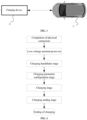
- FIG. 1 is a schematic diagram showing a physical connection between an electrical device 10 and a charging device 20.
- an electric car is taken as an example of the electrical device 10
- a charging pile is taken as an example of the charging device 20.
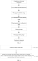
- FIG. 2 shows a general overall flow chart when the electrical device 10 is charged by the charging device 20.
- the general charging process includes completion of physical connection, low-voltage assisted power-on, a charging handshake stage, a charging parameter configuration stage, a charging stage, and a charging ending stage.
- a battery management system (BMS) on the electrical device 10 is a main body for controlling charging parameters, and the charging device 20 is a main body for executing the control.
- BMS battery management system
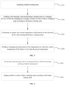
- FIG. 3 shows a general overall flow chart when the electrical device 10 is charged by the charging device 20 in a low-temperature environment. Compared with the charging process shown in FIG. 2 , a low-temperature pulse heating stage is added to the charging handshake stage and the charging parameter configuration stage.
- the battery management system BMS of the electrical device 10 judges whether the temperature of the battery meets the minimum temperature T min required for charging. If so, it enters the charging parameter configuration stage. If not, the battery management system BMS acquires the optimal charge and discharge frequency and a current upper limit of the battery under the current temperature and a state of health (SOH) by looking up a table, and the battery management system BMS sends a first instruction (the first instruction at least including the frequency and amplitude of the positive and negative alternating excitation current) to the charging device 20, and the charging device 20 charges and discharges the battery according to the first instruction to achieve low-temperature alternating excitation heating of the battery pack.
- SOH state of health
- the battery management system BMS judges whether the temperature of the battery meets the minimum temperature T min required for charging in real time, and adjusts the frequency and amplitude of the excitation current in real time.
- the battery management system BMS sends a second instruction (the first instruction at least including a outputting stop instruction) to the charging device 20, and the charging device 20 stops outputting the positive and negative alternating excitation current, i.e., stopping battery heating.
- An embodiment of the present application provides a battery charging control method used for the electrical device 10, and a specific main body for executing the control may be the battery management system BMS.
- the aforementioned method is applied after the low-temperature pulse heating stage and before the charging stage of the charging process shown in FIG. 3 .
- the method specifically includes the following steps:
- the charging device does not enter the battery charging stage when the battery heating state is the heating state; and the charging device enters the battery charging stage when the battery heating state is the heating completion state.
- the electrical device 10 and the charging device 20 are connected physically, and various pre-charging preparation stages need to be completed before the charging device 20 outputs power.
- the electrical device 10 acquires a battery heating state and sends a first message carrying the battery heating state to the charging device 20.
- the charging device 20 judges whether to enter the battery charging stage, i.e., whether to output power, according to the battery heating state.
- the electrical device 10 can autonomously implement a process of pulse heating followed by direct current (DC) charging by relying on the interaction with the charging device 20, thereby avoiding possible damage to the power battery caused by charging in a low-temperature environment. A user does not need to wait for the battery to complete self-heating before connecting the charging device for charging, thereby improving the experience of the user.
- DC direct current
- the current temperature of the battery before the battery heating state is acquired in the step S101, the current temperature of the battery can be acquired; when the current temperature of the battery is lower than the preset temperature, it is determined that the battery is in the heating state; and when the current temperature of the battery is greater than or equal to the preset temperature, it is determined that the battery is in the heating completion state.
- the preset temperature may be a minimum temperature T min that meets the charging requirement.
- the electrical device before acquiring the battery heating state, can judge whether the battery heating state is a heating state or a heating completion state according to the current temperature of the power battery, so that the electrical device can quickly acquire the battery heating state, thereby improving the efficiency of the electrical device in completing subsequent processes.
- the aforementioned battery charging control method may further include the following steps:
- the ambient temperature may continue to change, and thus the battery temperature also changes accordingly, which may cause that the electrical device is still charging when the battery temperature decreases. It may cause damage to the battery.
- the electrical device after entering the battery charging stage, the electrical device continues to acquire the temperature of the battery.
- a charging stop instruction is sent to the charging device to stop charging of the battery, thereby avoiding damage to the battery.
- the low-temperature pulse heating stage can be started again to heat the battery.
- the step S201 may be specifically implemented as: continuing to acquire the current temperature of the battery by the electrical device after entering the battery charging stage and a preset time has passed.
- the charging device judges whether to continue the charging of the battery according to the battery heating state, thereby achieving precise control of the battery charging.
- the step S102 may be specifically implemented as: sending the first message carrying the battery heating state to the charging device according to a first preset period.
- the electrical device periodically acquires the battery heating state, and sends the first message carrying the battery heating state to the charging device, so that the charging device can periodically acquire the battery heating state, thereby achieving precise control of battery charging.
- the aforementioned battery charging control method may further include the step of: receiving a second message sent by the charging device, the second message carrying a state of the charging device.
- the charging device sends a second message to the electrical device in the process when the battery is being heated.
- the electrical device can acquire the state of the charging device from the second message, so that normal communication is maintained between the electrical device and the charging device, and the electrical device can know the state of the charging device. If the electrical device cannot know the state of the charging device within a period of time, a charging timeout alarm will be issued, and the charging device will stop charging. If the user wants to start the charging again, the user must reconnect the electrical device and the charging device, which is very unfriendly to user operation. Therefore, this embodiment can avoid the inconvenience caused to the user by the interruption of the charging procedure.
- the aforementioned battery charging control method further includes the step of: adding a corresponding sending time tag to the first message and then storing the first message added with the corresponding sending time tag.
- the electrical device adds a corresponding sending time tag to the first message sent to the charging device and stores the first message added with the corresponding sending time tag for the user to view, thereby improving the experience of the user.
- the embodiment of the present application further provides a battery charging control method used for the charging device 20.
- the method corresponds to the battery charging control method used for the electrical device 10 in the aforementioned embodiment.
- the method specifically includes the following steps:
- the charging device does not enter the battery charging stage when the battery heating state is the heating state; and the charging device enters the battery charging stage when the battery heating state is the heating completion state.
- the charging device does not enter the battery charging stage, that is, the charging device does not output power, which can avoid possible damage to the power battery caused by charging in a low-temperature environment.
- the electrical device 10 and the charging device 20 are connected physically, and various pre-charging preparation stages need to be completed before the charging device 20 outputs power.
- the electrical device 10 acquires a battery heating state and sends a first message carrying the battery heating state to the charging device 20.
- the charging device 20 judges whether to enter the battery charging stage, i.e., whether to output power, according to the battery heating state.
- the charging device 20 can autonomously implement a process of pulse heating followed by direct current (DC) charging by relying on the interaction with the electrical device 10, thereby avoiding possible damage to the power battery caused by charging in a low-temperature environment and improving the experience of the user.
- DC direct current
- the aforementioned battery charging control method further includes the step of: S401. sending a second message to the electrical device when the battery heating state is the heating state, the second message carrying a state of the charging device.
- the charging device when the battery is in the heating state, the charging device cannot charge the battery. In order to maintain the normal communication with the electrical device, the charging device sends the second message to the electrical device, so that the electrical device can know the current state of the charging device, thereby avoiding inconvenience to the user caused by interruption of the charging procedure.
- the step S401 may be specifically implemented as: sending the second message to the electrical device according to a second preset period when the battery heating state is the heating state.
- the second message is sent periodically, so that the electrical device can regularly know the current state of the charging device, thereby avoiding inconvenience to the user caused by interruption of the charging procedure.
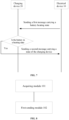
- FIG. 7 shows a schematic diagram showing a flow chart of interaction between the electrical device 10 and the charging device 20.
- the present application further provides a battery charging control apparatus used for an electrical device.
- the battery charging control apparatus includes:
- the acquiring module 101 before acquiring the battery heating state, is further used for:
- the acquiring module 101 is further used for:
- the acquiring module 101 is further used for: continuing to acquire the current temperature of the battery by the electrical device after entering the battery charging stage and a preset time has passed.
- the first sending module 102 is specifically used for: sending the first message carrying the battery heating state to the charging device according to a first preset period.
- the aforementioned apparatus further includes: a receiving module for receiving a second message sent by the charging device, the second message carrying a state of the charging device.
- the aforementioned apparatus further includes: a storage module for adding a corresponding sending time tag to the first message and then storing the first message added with the corresponding sending time tag.
- the battery charging control apparatus provided in the aforementioned embodiment of the present application and the battery charging control method used for the electrical device provided in the embodiment of the present application are based on the same inventive concept and have the same beneficial effect.
- the present application further provides a battery charging control apparatus used for a charging device.
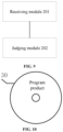
- the battery charging control apparatus includes:
- the judging module 202 is specifically used for:
- the aforementioned apparatus further includes: a second sending module for sending a second message to the electrical device when the battery heating state is the heating state, the second message carrying a state of the charging device.
- the second sending module is specifically used for: sending the second message to the electrical device according to a second preset period when the battery heating state is the heating state.
- the battery charging control apparatus provided in the aforementioned embodiment of the present application and the battery charging control method used for the charging device provided in the embodiment of the present application are based on the same inventive concept and have the same beneficial effect.
- the present application further provides an electrical device, including: a memory, a processor, and a computer program stored on the memory and runnable on the processor, wherein when run by the processor, the computer program is executed to implement the battery charging control method used for the electrical device in the aforementioned embodiment.
- the electrical device may be an electric vehicle, an electric toy, a ship, a spacecraft, etc. having components such as a power battery, a motor, and a motor inverter.
- the electrical device provided in the aforementioned embodiment of the present application and the battery charging control method used for the electrical device provided in the embodiment of the present application are based on the same inventive concept and have the same beneficial effect.
- the present application further provides a charging device, including: a memory, a processor, and a computer program stored on the memory and runnable on the processor, wherein when run by the processor, the computer program is executed to implement the battery charging control method used for the charging device in the aforementioned embodiment.
- the charging device provided in the aforementioned embodiment of the present application and the battery charging control method used for the charging device provided in the embodiment of the present application are based on the same inventive concept and have the same beneficial effect.
- the processor may be an integrated circuit chip with signal processing capability.
- each step of the aforementioned method can be completed by an integrated logic circuit of hardware in the processor or an instruction in the form of software.
- the aforementioned processor can be a general-purpose processor, including a central processing unit (CPU), a network processor (NP), etc.; or it may also be a digital signal processor (DSP), an application-specific integrated circuit (ASIC), a field-programmable gate array (FPGA) or other programmable logic devices, discrete gates or transistor logic devices, and discrete hardware components.
- DSP digital signal processor
- ASIC application-specific integrated circuit
- FPGA field-programmable gate array
- a general-purpose processor may be a microprocessor, or the processor may be any conventional processor, etc.
- the steps of the method disclosed in the embodiments of the present application can be directly embodied as being executed by a hardware decoding processor, or executed by a combination of hardware and software modules in the decoding processor.
- the software module may be located in a random access memory, a flash memory, a read-only memory, a programmable read-only memory, or an electrically erasable programmable memory, a register, or the like mature storage media in the art.
- the storage medium is located in the memory, and the processor reads the information in the memory and completes the steps of the aforementioned method in combination with the hardware of the processor.
- the memory may include high-speed random access memory (RAM), and may also include nonvolatile memory, for example at least one disk storage.
- RAM random access memory
- nonvolatile memory for example at least one disk storage.
- the communication connection between the apparatus network element and at least one other network element is achieved through at least one communication interface (which can be wired or wireless), and an Internet, a wide area network, a local area network, a metropolitan area network, etc. can be used.
- the memory is used for storing programs, and the processor executes the program after receiving an execution instruction.
- the battery charging control method disclosed in any implementation of the aforementioned embodiment of the present application can be applied to the processor or implemented by the processor.
- An embodiment of the present application further provides a computer-readable storage medium corresponding to the battery charging control method provided in the aforementioned implementation.
- the computer-readable storage medium is an optical disk 30, on which a computer program (i.e., a program product) is stored.
- the computer program When run by the processor, the computer program will execute the battery charging control method provided in any of the aforementioned implementations.
- examples of the computer-readable storage medium may also include, but are not limited to, phase-change random access memory (PRAM), static random access memory (SRAM), dynamic random access memory (DRAM), other types of random access memory (RAM), read-only memory (ROM), electrically erasable programmable read-only memory (EEPROM), flash memory or other optical or magnetic storage media, which are not listed here one by one anymore.
- PRAM phase-change random access memory
- SRAM static random access memory
- DRAM dynamic random access memory
- RAM random access memory
- ROM read-only memory
- EEPROM electrically erasable programmable read-only memory
- flash memory or other optical or magnetic storage media, which are not listed here one by one anymore.
- the computer-readable storage medium provided in the aforementioned embodiments of the present application and the battery charging control method provided in the embodiments of the present application are based on the same inventive concept and have the same beneficial effect as the methods adopted, run or implemented by the application programs stored therein.
Landscapes
- Engineering & Computer Science (AREA)
- Power Engineering (AREA)
- Transportation (AREA)
- Mechanical Engineering (AREA)
- Chemical Kinetics & Catalysis (AREA)
- Manufacturing & Machinery (AREA)
- Chemical & Material Sciences (AREA)
- Electrochemistry (AREA)
- General Chemical & Material Sciences (AREA)
- Sustainable Development (AREA)
- Sustainable Energy (AREA)
- Life Sciences & Earth Sciences (AREA)
- Charge And Discharge Circuits For Batteries Or The Like (AREA)
Abstract
Description
- The present application claims priority to
Chinese patent application No. 202210435627.4 filed with the China National Intellectual Property Administration on April 24, 2022 - The present application relates to the technical field of batteries, and in particular to a battery charging control method and apparatus, an electronic device, a charging device, and a storage medium.
- Intellectualization and electrification are one of the important development directions in the field of intelligent transportation. Especially in the field of electrification, with the advancement of materials and technology, the energy density of battery packs is getting higher and higher, and vehicles are also using various types of battery packs as energy sources. Compared with traditional vehicles that mainly use fossil fuels as energy sources, modem vehicles are increasingly using battery packs represented by lithium-ion power batteries as energy sources.
- Most of the existing methods for charging power batteries adopt national standard procedures, but the national standard procedures are not suitable for all scenarios. In some special scenarios, they may instead cause damage to the power batteries. For example, charging in a low-temperature environment may lead to the risk of lithium plating in the batteries.
- In view of the aforementioned problem, the present application provides a battery charging control method and apparatus, an electrical device, a charging device, and a storage medium, which can avoid possible damage caused by charging a power battery in a low-temperature environment.
- In a first aspect, the present application provides a battery charging control method used for an electrical device, including:
- acquiring a battery heating state; and
- sending a first message carrying the battery heating state to a charging device, so that the charging device judges whether to enter a battery charging stage according to the battery heating state;
- wherein the battery heating state is a heating state or a heating completion state.
- In the technical solution of the embodiment of the present application, the electrical device and the charging device are connected physically, and various pre-charging preparation stages need to be completed before the charging device outputs power. After the low-temperature pulse heating stage of the power battery, the electrical device acquires a battery heating state and sends a first message carrying the battery heating state to the charging device. The charging device judges whether to enter the battery charging stage, i.e., whether to output power, according to the battery heating state. The electrical device can autonomously implement a process of pulse heating followed by direct current (DC) charging by relying on the interaction with the charging device, thereby avoiding possible damage to the power battery caused by charging in a low-temperature environment. A user does not need to wait for the battery to complete self-heating before connecting the charging device for charging, thereby improving the experience of the user.
- In some embodiments, before the acquiring a battery heating state, the method further includes:
- acquiring a current temperature of the battery;
- determining that the battery is in the heating state when the current temperature of the battery is less than a preset temperature; and
- determining that the battery is in the heating completion state when the current temperature of the battery is greater than or equal to the preset temperature.
- In an embodiment of the present application, before acquiring the battery heating state, the electrical device can judge whether the battery heating state is a heating state or a heating completion state according to the current temperature of the power battery, so that the electrical device can quickly acquire the battery heating state, thereby improving the efficiency of the electrical device in completing subsequent processes.
- In some embodiments, the method further includes:
- continuing to acquire the current temperature of the battery by the electrical device after entering the battery charging stage; and
- sending a charging stop instruction to the charging device when the current temperature of the battery is less than the preset temperature.
- In an embodiment of the present application, when the electrical device is being charged, the ambient temperature may continue to change, and thus the battery temperature also changes accordingly, which may cause that the electrical device is still charging when the battery temperature decreases. It may cause damage to the battery. In the present embodiment, after entering the battery charging stage, the electrical device continues to acquire the temperature of the battery. When the temperature of the battery is lower than a preset temperature required for charging, a charging stop instruction is sent to the charging device to stop charging of the battery, thereby avoiding damage to the battery. Afterwards, the low-temperature pulse heating stage can be started again to heat the battery.
- In some embodiments, after entering the battery charging stage, the electrical device continues to acquire the current temperature of the battery, including: continuing to acquire the current temperature of the battery by the electrical device after entering the battery charging stage and a preset time has passed.
- In this embodiment, when the battery of the electrical device is charged by the charging device, the temperature of the battery will rise as the charging progresses within the preset time, but after the preset time, there is a situation in which the electrical device is still being charged when the temperature of the battery decreases, which may cause damage to the battery. In this embodiment, after the preset time, the charging device judges whether to continue the charging of the battery according to the battery heating state, thereby achieving precise control of the battery charging.
- In some embodiments, the sending a first message carrying the battery heating state to a charging device includes: sending the first message carrying the battery heating state to the charging device according to a first preset period.
- In this embodiment, the electrical device periodically acquires the battery heating state, and sends the first message carrying the battery heating state to the charging device, so that the charging device can periodically acquire the battery heating state, thereby achieving precise control of battery charging.
- In some embodiments, the method further includes: receiving a second message sent by the charging device, the second message carrying a state of the charging device.
- In this embodiment, after receiving the second message sent by the charging device, the electrical device can acquire the state of the charging device from the second message, so that normal communication is maintained between the electrical device and the charging device, thereby avoiding inconvenience caused to the user by interruption of the charging procedure.
- In some embodiments, the method further includes: adding a corresponding sending time tag to the first message and then storing the first message added with the corresponding sending time tag.
- In this embodiment, the electrical device adds a corresponding sending time tag to the first message sent to the charging device and stores the first message added with the corresponding sending time tag for the user to view, thereby improving the experience of the user.
- In a second aspect, the present application provides a battery charging control method used for a charging device, including:
- receiving a first message sent by an electrical device, the first message carrying a battery heating state; and
- judging whether to enter a battery charging stage according to the battery heating state;
- wherein the battery heating state is a heating state or a heating completion state.
- In the technical solution of the embodiment of the present application, the electrical device and the charging device are connected physically, and various pre-charging preparation stages need to be completed before the charging device outputs power. In the low-temperature pulse heating stage of the power battery, the electrical device acquires a battery heating state and sends a first message carrying the battery heating state to the charging device. The charging device judges whether to enter the battery charging stage, i.e., whether to output power, according to the battery heating state. The charging device can autonomously implement a process of pulse heating followed by direct current (DC) charging by relying on the interaction with the electrical device, thereby avoiding possible damage to the power battery caused by charging in a low-temperature environment, thereby improving the experience of the user.
- In some embodiments, the judging whether to enter a battery charging stage according to the battery heating state includes:
- not allowing the charging device to enter the battery charging stage when the battery heating state is the heating state; and
- allowing the charging device to enter the battery charging stage when the battery heating state is the heating completion state.
- In this embodiment, when the battery is being heated, the charging device does not enter the battery charging stage, that is, the charging device does not output power, which can avoid possible damage to the power battery caused by charging in a low-temperature environment.
- In some embodiments, the method further includes: sending a second message to the electrical device when the battery heating state is the heating state, the second message carrying a state of the charging device.
- In this embodiment, when the battery is in the heating state, the charging device cannot charge the battery. In order to maintain the normal communication with the electrical device, the charging device sends the second message to the electrical device, so that the electrical device can know the current state of the charging device, thereby avoiding inconvenience to the user caused by interruption of the charging procedure.
- In some embodiments, the sending a second message to the electrical device when the battery heating state is the heating state includes: sending the second message to the electrical device according to a second preset period when the battery heating state is the heating state.
- In this embodiment, the second message is sent periodically, so that the electrical device can regularly learn the current state of the charging device, thereby achieving precise control of battery charging.
- In a third aspect, the present application provides a battery charging control apparatus used for an electrical device, including:
- an acquiring module for acquiring a battery heating state; and
- a first sending module for sending a first message carrying the battery heating state to a charging device, so that the charging device judges whether to enter a battery charging stage according to the battery heating state;
- wherein the battery heating state is a heating state or a heating completion state.
- In a fourth aspect, the present application provides a battery charging control apparatus used for a charging device, including:
- a receiving module for receiving a first message sent by an electrical device, the first message carrying a battery heating state; and
- a judging module for judging whether to enter a battery charging stage according to the battery heating state;
- wherein the battery heating state is a heating state or a heating completion state.
- In a fifth aspect, the present application provides an electrical device, including: a memory, a processor, and a computer program stored on the memory and runnable on the processor, wherein when run by the processor, the computer program is executed to implement the method of the first aspect.
- In a sixth aspect, the present application provides a charging device, including: a memory, a processor, and a computer program stored on the memory and runnable on the processor, wherein when run by the processor, the computer program is executed to implement the method of the second aspect.
- In a seventh aspect, the present application provides a computer-readable storage medium on which computer-readable instructions are stored, wherein the computer-readable instructions are executable by a processor to implement the method of the first aspect or the second aspect.
- The above description is only an overview of the technical solution of the present application. In order to better understand the technical means of the present application and thus implement them according to the contents of the specification, and in order to make the above and other objectives, features and advantages of the present application more obvious and understandable, the following is the detailed description of the present application.
- Various other advantages and benefits will become apparent to those of ordinary skill in the art upon reading the following detailed description of the preferred embodiments. The drawings are for the purpose of illustrating the preferred implementations only and are not to be considered a limitation to the present application. Also, the same components are denoted by the same reference numerals throughout the drawings. In the accompanying drawings:
-
FIG. 1 is a schematic diagram showing a physical connection between an electrical device and a charging device; -
FIG. 2 shows a general overall flow chart when the electrical device is charged by the charging device; -
FIG. 3 shows a general overall flow chart when the electrical device is charged by the charging device in a low-temperature environment; -
FIG. 4 shows one of the flow charts of a battery charging control method for an electrical device provided by the present application; -
FIG. 5 shows the second one of the flow charts of a battery charging control method for an electrical device provided by the present application; -
FIG. 6 shows a flow chart of a battery charging control method for a charging device provided by the present application; -
FIG. 7 is a schematic diagram showing a flow chart of interaction between the electrical device and the charging device provided by the present application; -
FIG. 8 shows a schematic structural view of a battery charging control apparatus for the electrical device provided by the present application; -
FIG. 9 shows a schematic structural view of a battery charging control apparatus for the charging device provided by the present application; and -
FIG. 10 shows a schematic structural view of a readable storage medium provided by the present application. - Embodiments of the technical solutions of the present application will be described in detail below with reference to the accompanying drawings. The following embodiments are only used to more clearly illustrate the technical solution of the present application, and therefore are only used as examples and cannot be used to limit the scope of protection of the present application.
- Unless otherwise defined, all technical and scientific terms used herein have the same meanings as those commonly understood by those skilled in the art to which the present application pertains to. the terms used herein are for the purpose of describing specific embodiments only, and are not intended to limit the present application. The terms "including" and "having" and any variations thereof in the description and claims of the present application and the aforementioned description of the drawings are intended to cover non-exclusive inclusion.
- In the description of the embodiments of the present application, the technical terms "first", "second", and the like are used only to distinguish between different objects, and are not to be understood as indicating or implying a relative importance or implicitly specifying the number, particular order, or primary and secondary relation of the technical features indicated. In the description of the embodiments of the present application, the meaning of "a plurality of" is two or more, unless otherwise explicitly and specifically defined.
- Reference herein to "an embodiment" means that a particular feature, structure, or characteristic described in connection with the embodiment can be included in at least one embodiment of the present application. The appearance of this phrase in various places in the specification does not necessarily refer to the same embodiment, nor is it a separate or alternative embodiment that is mutually exclusive with other embodiments. It is explicitly and implicitly understood by those skilled in the art that the embodiments described herein may be combined with other embodiments.
- In the description of the embodiments of the present application, the term "and/or" is simply a description of an association of associated objects, which indicates that there may exist three relationships, for example, A and/or B may mean: the presence of A, the presence of both A and B, and the presence of B. In addition, the character "/" herein generally means that the associated objects before and after it are in an "or" relationship.
- In the description of the embodiments of the present application, the term "a plurality of" refers to two or more (including two). Similarly, "multiple groups" refers to two or more groups (including two groups), and "multiple pieces" refers to two or more pieces (including two pieces).
- In the description of the embodiments of the present application, the orientation or positional relationships indicated by the technical terms "center", "longitudinal", "transverse", "length", "width", "thickness", "upper", "lower", "front", "back", "left", "right", "vertical", "horizontal", "top", "bottom", "inner", "outer", "clockwise", "counterclockwise", "axial", "radial", "circumferential", etc. are based on the orientation or positional relationships shown in the accompanying drawings, and are only for convenience of description of the present application and simplification of the description, rather than indicating or implying that the indicated device or element must have a specific orientation, be constructed and operate in a specific orientation, and therefore, cannot be understood as a limitation to the present application.
- In the description of the embodiments of the present application, unless otherwise specified and limited, the technical terms "mounting", "connection", "connection" and "fixation" should be understood in a broad sense, for example, they can be fixed connection, detachable connection, or integration; or they can be mechanical connection or electrical connection; or they can be direct connection, indirect connection through an intermediate medium, or communication of the interiors of two elements or the relationship of interaction between two elements. For those of ordinary skill in the art, the specific meanings of the above terms in the embodiments of the present application can be understood according to specific situations.
- At present, from the perspective of the development of the market situation, power batteries are increasingly more widely used. Power batteries are not only applied in energy storage power source systems such as water, fire, wind and solar power stations, but also widely applied in electric transport tools, such as electric bicycles, electric motorcycles, and electric vehicles, as well as many fields, such as military equipment and aerospace. As the application fields of the power batteries continue to expand, their market demand is also constantly expanding.
- The inventors have noticed that in an environment of minus thirty degrees Celsius, the charging performance of battery packs represented by lithium batteries is basically zero, and the discharging performance of them is also very poor. Therefore, studying the low-temperature rapid heating of battery packs is very important for improving the adaptability of the electrical device to the environment. For example, an electric car owner parks his/her car and plugs a charging gun into the car to charge it before leaving. However, at this time the temperature of the battery is too low to charge directly, and direct charging will damage the battery. Based on a current phenomenon in which the low-temperature environment has a great impact on the charging performance of the battery pack, it has become a focus of the present application how to control the battery pack to heat up quickly before charging.
- In order to solve the problem of battery damage caused by charging in the low-temperature environment, the applicant has found by research that the existing charging process can be improved to achieve charging in the low-temperature environment without damaging the battery. Specifically, the charging device is controlled to output power to charge the battery of the electrical device after the heating of the battery is completed. For example, after it is determined that the battery is heated to about 0 degrees, then the battery is charged by the charging device.
- Based on the aforementioned considerations, in order to solve the problem of battery damage caused by charging in the low-temperature environment, the inventors have designed a battery charging control method after in-depth research. The electrical device and the charging device are physically connected. Various pre-charging preparation stages need to be completed before the charging device outputs power. After the low-temperature pulse heating stage of the power battery, the electrical device acquires the battery heating state and sends a message carrying the battery heating state to the charging device. The charging device judges whether to enter the battery charging stage, i.e., whether to output power, according to the battery heating state. When the battery is being heated, the charging device does not enter the battery charging stage, that is, the charging device does not output power, and sends a message carrying the charging device state to the electrical device, so as to maintain normal communication with the electrical device and avoid interruption of the charging process due to long-term lack of communication between the two.
- Through the aforementioned manner, the electrical device can autonomously implement the process of pulse heating followed by DC charging by relying on the interaction with the charging device, thereby avoiding possible damage to a power battery caused by charging in a low-temperature environment. A user does not need to wait for the battery to complete self-heating before connecting the charging device for charging, thereby improving the experience of the user.
- The battery charging control method disclosed in the embodiment of the present application can be used in, but is not limited to, electric toys, electric tools, battery cars, electric cars, ships, spacecraft and the like electrical devices. Electric toys can include fixed or mobile electric toys, e.g., game consoles, electric car toys, electric ship toys, and electric airplane toys, etc., and the spacecraft can include airplanes, rockets, space shuttles, and spaceships, etc.
-
FIG. 1 is a schematic diagram showing a physical connection between anelectrical device 10 and a chargingdevice 20. For ease of understanding, in the present application, an electric car is taken as an example of theelectrical device 10, and a charging pile is taken as an example of the chargingdevice 20. -
FIG. 2 shows a general overall flow chart when theelectrical device 10 is charged by the chargingdevice 20. The general charging process includes completion of physical connection, low-voltage assisted power-on, a charging handshake stage, a charging parameter configuration stage, a charging stage, and a charging ending stage. A battery management system (BMS) on theelectrical device 10 is a main body for controlling charging parameters, and the chargingdevice 20 is a main body for executing the control. -
FIG. 3 shows a general overall flow chart when theelectrical device 10 is charged by the chargingdevice 20 in a low-temperature environment. Compared with the charging process shown inFIG. 2 , a low-temperature pulse heating stage is added to the charging handshake stage and the charging parameter configuration stage. - In the low-temperature pulse heating stage, the battery management system BMS of the
electrical device 10 judges whether the temperature of the battery meets the minimum temperature Tmin required for charging. If so, it enters the charging parameter configuration stage. If not, the battery management system BMS acquires the optimal charge and discharge frequency and a current upper limit of the battery under the current temperature and a state of health (SOH) by looking up a table, and the battery management system BMS sends a first instruction (the first instruction at least including the frequency and amplitude of the positive and negative alternating excitation current) to the chargingdevice 20, and the chargingdevice 20 charges and discharges the battery according to the first instruction to achieve low-temperature alternating excitation heating of the battery pack. During the heating process, the battery management system BMS judges whether the temperature of the battery meets the minimum temperature Tmin required for charging in real time, and adjusts the frequency and amplitude of the excitation current in real time. When the temperature of the battery meets the minimum temperature Tmin required for charging, the battery management system BMS sends a second instruction (the first instruction at least including a outputting stop instruction) to the chargingdevice 20, and the chargingdevice 20 stops outputting the positive and negative alternating excitation current, i.e., stopping battery heating. - An embodiment of the present application provides a battery charging control method used for the
electrical device 10, and a specific main body for executing the control may be the battery management system BMS. The aforementioned method is applied after the low-temperature pulse heating stage and before the charging stage of the charging process shown inFIG. 3 . - Referring to the flow chart of the battery charging control method shown in
FIG. 4 , the method specifically includes the following steps: - S101. acquiring a battery heating state; and
- S102. sending a first message carrying the battery heating state to a charging device, so that the charging device judges whether to enter a battery charging stage according to the battery heating state;
wherein the battery heating state is a heating state or a heating completion state. The heating state indicates that the temperature of the battery has not yet met the minimum temperature Tmin required for charging, and the heating completion state indicates that the temperature of the battery meets the minimum temperature Tmin required for charging. - Specifically, the charging device does not enter the battery charging stage when the battery heating state is the heating state; and the charging device enters the battery charging stage when the battery heating state is the heating completion state.
- In this embodiment, referring to
FIG. 1 , theelectrical device 10 and the chargingdevice 20 are connected physically, and various pre-charging preparation stages need to be completed before the chargingdevice 20 outputs power. After the low-temperature pulse heating stage of the power battery, theelectrical device 10 acquires a battery heating state and sends a first message carrying the battery heating state to the chargingdevice 20. The chargingdevice 20 judges whether to enter the battery charging stage, i.e., whether to output power, according to the battery heating state. Theelectrical device 10 can autonomously implement a process of pulse heating followed by direct current (DC) charging by relying on the interaction with the chargingdevice 20, thereby avoiding possible damage to the power battery caused by charging in a low-temperature environment. A user does not need to wait for the battery to complete self-heating before connecting the charging device for charging, thereby improving the experience of the user. - According to some embodiments of the present application, before the battery heating state is acquired in the step S101, the current temperature of the battery can be acquired; when the current temperature of the battery is lower than the preset temperature, it is determined that the battery is in the heating state; and when the current temperature of the battery is greater than or equal to the preset temperature, it is determined that the battery is in the heating completion state. The preset temperature may be a minimum temperature Tmin that meets the charging requirement.
- In an embodiment of the present application, before acquiring the battery heating state, the electrical device can judge whether the battery heating state is a heating state or a heating completion state according to the current temperature of the power battery, so that the electrical device can quickly acquire the battery heating state, thereby improving the efficiency of the electrical device in completing subsequent processes.
- According to some embodiments of the present application, referring to
FIG. 5 , the aforementioned battery charging control method may further include the following steps: - S201. continuing to acquire the current temperature of the battery by the electrical device after entering the battery charging stage; and
- S202. sending a charging stop instruction to the charging device when the current temperature of the battery is less than the preset temperature.
- In an embodiment of the present application, when the electrical device is being charged, the ambient temperature may continue to change, and thus the battery temperature also changes accordingly, which may cause that the electrical device is still charging when the battery temperature decreases. It may cause damage to the battery. In the present embodiment, after entering the battery charging stage, the electrical device continues to acquire the temperature of the battery. When the temperature of the battery is lower than a preset temperature required for charging, a charging stop instruction is sent to the charging device to stop charging of the battery, thereby avoiding damage to the battery. Afterwards, the low-temperature pulse heating stage can be started again to heat the battery.
- According to some embodiments of the present application, the step S201 may be specifically implemented as: continuing to acquire the current temperature of the battery by the electrical device after entering the battery charging stage and a preset time has passed.
- In this embodiment, when the battery of the electrical device is charged by the charging device, the temperature of the battery will rise as the charging progresses within the preset time, but after the preset time (e.g., 1 hour), there is a situation in which the electrical device is still being charged when the temperature of the battery decreases, which may cause damage to the battery. In this embodiment, after the preset time, the charging device judges whether to continue the charging of the battery according to the battery heating state, thereby achieving precise control of the battery charging.
- According to some embodiments of the present application, the step S102 may be specifically implemented as: sending the first message carrying the battery heating state to the charging device according to a first preset period.
- In this embodiment, the electrical device periodically acquires the battery heating state, and sends the first message carrying the battery heating state to the charging device, so that the charging device can periodically acquire the battery heating state, thereby achieving precise control of battery charging.
- According to some embodiments of the present application, the aforementioned battery charging control method may further include the step of: receiving a second message sent by the charging device, the second message carrying a state of the charging device.
- In this embodiment, the charging device sends a second message to the electrical device in the process when the battery is being heated. After receiving the second message sent by the charging device, the electrical device can acquire the state of the charging device from the second message, so that normal communication is maintained between the electrical device and the charging device, and the electrical device can know the state of the charging device. If the electrical device cannot know the state of the charging device within a period of time, a charging timeout alarm will be issued, and the charging device will stop charging. If the user wants to start the charging again, the user must reconnect the electrical device and the charging device, which is very unfriendly to user operation. Therefore, this embodiment can avoid the inconvenience caused to the user by the interruption of the charging procedure.
- According to some embodiments of the present application, the aforementioned battery charging control method further includes the step of: adding a corresponding sending time tag to the first message and then storing the first message added with the corresponding sending time tag.
- In this embodiment, the electrical device adds a corresponding sending time tag to the first message sent to the charging device and stores the first message added with the corresponding sending time tag for the user to view, thereby improving the experience of the user.
- The embodiment of the present application further provides a battery charging control method used for the charging
device 20. The method corresponds to the battery charging control method used for theelectrical device 10 in the aforementioned embodiment. - Referring to the flow chart of the battery charging control method shown in
FIG. 6 , the method specifically includes the following steps: - S301. receiving a first message sent by an electrical device, the first message carrying a battery heating state; and
- S302. judging whether to enter a battery charging stage according to the battery heating state;
wherein the battery heating state is a heating state or a heating completion state. The heating state indicates that the temperature of the battery has not yet met the minimum temperature Tmin required for charging, and the heating completion state indicates that the temperature of the battery meets the minimum temperature Tmin required for charging. - According to some embodiments of the present application, the charging device does not enter the battery charging stage when the battery heating state is the heating state; and the charging device enters the battery charging stage when the battery heating state is the heating completion state. When the battery is being heated, the charging device does not enter the battery charging stage, that is, the charging device does not output power, which can avoid possible damage to the power battery caused by charging in a low-temperature environment.
- In this embodiment, referring to
FIG. 1 , theelectrical device 10 and the chargingdevice 20 are connected physically, and various pre-charging preparation stages need to be completed before the chargingdevice 20 outputs power. In the low-temperature pulse heating stage of the power battery, theelectrical device 10 acquires a battery heating state and sends a first message carrying the battery heating state to the chargingdevice 20. The chargingdevice 20 judges whether to enter the battery charging stage, i.e., whether to output power, according to the battery heating state. The chargingdevice 20 can autonomously implement a process of pulse heating followed by direct current (DC) charging by relying on the interaction with theelectrical device 10, thereby avoiding possible damage to the power battery caused by charging in a low-temperature environment and improving the experience of the user. - According to some embodiments of the present application, the aforementioned battery charging control method further includes the step of:
S401. sending a second message to the electrical device when the battery heating state is the heating state, the second message carrying a state of the charging device. - In this embodiment, when the battery is in the heating state, the charging device cannot charge the battery. In order to maintain the normal communication with the electrical device, the charging device sends the second message to the electrical device, so that the electrical device can know the current state of the charging device, thereby avoiding inconvenience to the user caused by interruption of the charging procedure.
- According to some embodiments of the present application, the step S401 may be specifically implemented as: sending the second message to the electrical device according to a second preset period when the battery heating state is the heating state.
- In this embodiment, the second message is sent periodically, so that the electrical device can regularly know the current state of the charging device, thereby avoiding inconvenience to the user caused by interruption of the charging procedure.
- For ease of understanding,
FIG. 7 shows a schematic diagram showing a flow chart of interaction between theelectrical device 10 and the chargingdevice 20. - The present application further provides a battery charging control apparatus used for an electrical device. As shown in
FIG. 8 , the battery charging control apparatus includes: - an acquiring
module 101 for acquiring a battery heating state; and - a
first sending module 102 for sending a first message carrying the battery heating state to a charging device, so that the charging device judges whether to enter a battery charging stage according to the battery heating state; - wherein the battery heating state is a heating state or a heating completion state.
- According to some embodiments of the present application, before acquiring the battery heating state, the acquiring
module 101 is further used for: - acquiring a current temperature of the battery;
- determining that the battery is in the heating state when the current temperature of the battery is less than a preset temperature; and
- determining that the battery is in the heating completion state when the current temperature of the battery is greater than or equal to the preset temperature.
- According to some embodiments of the present application, the acquiring
module 101 is further used for: - continuing to acquire the current temperature of the battery by the electrical device after entering the battery charging stage; and
- sending a charging stop instruction to the charging device when the current temperature of the battery is less than the preset temperature.
- According to some embodiments of the present application, the acquiring
module 101 is further used for:
continuing to acquire the current temperature of the battery by the electrical device after entering the battery charging stage and a preset time has passed. - According to some embodiments of the present application, the
first sending module 102 is specifically used for:
sending the first message carrying the battery heating state to the charging device according to a first preset period. - According to some embodiments of the present application, the aforementioned apparatus further includes:
a receiving module for receiving a second message sent by the charging device, the second message carrying a state of the charging device. - According to some embodiments of the present application, the aforementioned apparatus further includes:
a storage module for adding a corresponding sending time tag to the first message and then storing the first message added with the corresponding sending time tag. - The battery charging control apparatus provided in the aforementioned embodiment of the present application and the battery charging control method used for the electrical device provided in the embodiment of the present application are based on the same inventive concept and have the same beneficial effect.
- The present application further provides a battery charging control apparatus used for a charging device. As shown in
FIG. 9 , the battery charging control apparatus includes: - a
receiving module 201 for receiving a first message sent by an electrical device, the first message carrying a battery heating state; and - a judging
module 202 for judging whether to enter a battery charging stage according to the battery heating state; - wherein the battery heating state is a heating state or a heating completion state.
- According to some embodiments of the present application, the judging
module 202 is specifically used for: - not allowing the charging device to enter the battery charging stage when the battery heating state is the heating state; and
- allowing the charging device to enter the battery charging stage when the battery heating state is the heating completion state.
- According to some embodiments of the present application, the aforementioned apparatus further includes:
a second sending module for sending a second message to the electrical device when the battery heating state is the heating state, the second message carrying a state of the charging device. - According to some embodiments of the present application, the second sending module is specifically used for:
sending the second message to the electrical device according to a second preset period when the battery heating state is the heating state. - The battery charging control apparatus provided in the aforementioned embodiment of the present application and the battery charging control method used for the charging device provided in the embodiment of the present application are based on the same inventive concept and have the same beneficial effect.
- The present application further provides an electrical device, including: a memory, a processor, and a computer program stored on the memory and runnable on the processor, wherein when run by the processor, the computer program is executed to implement the battery charging control method used for the electrical device in the aforementioned embodiment. The electrical device may be an electric vehicle, an electric toy, a ship, a spacecraft, etc. having components such as a power battery, a motor, and a motor inverter.
- The electrical device provided in the aforementioned embodiment of the present application and the battery charging control method used for the electrical device provided in the embodiment of the present application are based on the same inventive concept and have the same beneficial effect.
- The present application further provides a charging device, including: a memory, a processor, and a computer program stored on the memory and runnable on the processor, wherein when run by the processor, the computer program is executed to implement the battery charging control method used for the charging device in the aforementioned embodiment.
- The charging device provided in the aforementioned embodiment of the present application and the battery charging control method used for the charging device provided in the embodiment of the present application are based on the same inventive concept and have the same beneficial effect.
- In the aforementioned electrical device and charging device, the processor may be an integrated circuit chip with signal processing capability. In the implementation process, each step of the aforementioned method can be completed by an integrated logic circuit of hardware in the processor or an instruction in the form of software. The aforementioned processor can be a general-purpose processor, including a central processing unit (CPU), a network processor (NP), etc.; or it may also be a digital signal processor (DSP), an application-specific integrated circuit (ASIC), a field-programmable gate array (FPGA) or other programmable logic devices, discrete gates or transistor logic devices, and discrete hardware components. The various methods, steps and logic block diagrams disclosed in the embodiments of the present application can be implemented or executed. A general-purpose processor may be a microprocessor, or the processor may be any conventional processor, etc. The steps of the method disclosed in the embodiments of the present application can be directly embodied as being executed by a hardware decoding processor, or executed by a combination of hardware and software modules in the decoding processor. The software module may be located in a random access memory, a flash memory, a read-only memory, a programmable read-only memory, or an electrically erasable programmable memory, a register, or the like mature storage media in the art. The storage medium is located in the memory, and the processor reads the information in the memory and completes the steps of the aforementioned method in combination with the hardware of the processor.
- The memory may include high-speed random access memory (RAM), and may also include nonvolatile memory, for example at least one disk storage. The communication connection between the apparatus network element and at least one other network element is achieved through at least one communication interface (which can be wired or wireless), and an Internet, a wide area network, a local area network, a metropolitan area network, etc. can be used.
- The memory is used for storing programs, and the processor executes the program after receiving an execution instruction. The battery charging control method disclosed in any implementation of the aforementioned embodiment of the present application can be applied to the processor or implemented by the processor.
- An embodiment of the present application further provides a computer-readable storage medium corresponding to the battery charging control method provided in the aforementioned implementation. Please refer to
FIG. 10 , which shows that the computer-readable storage medium is anoptical disk 30, on which a computer program (i.e., a program product) is stored. When run by the processor, the computer program will execute the battery charging control method provided in any of the aforementioned implementations. - It should be noted that examples of the computer-readable storage medium may also include, but are not limited to, phase-change random access memory (PRAM), static random access memory (SRAM), dynamic random access memory (DRAM), other types of random access memory (RAM), read-only memory (ROM), electrically erasable programmable read-only memory (EEPROM), flash memory or other optical or magnetic storage media, which are not listed here one by one anymore.
- The computer-readable storage medium provided in the aforementioned embodiments of the present application and the battery charging control method provided in the embodiments of the present application are based on the same inventive concept and have the same beneficial effect as the methods adopted, run or implemented by the application programs stored therein.
- Finally, it should be noted that: the aforementioned embodiments are only used for illustrating the technical solution of the present application, rather than limiting it. Although the present application has been described in detail with reference to the foregoing embodiments, it should be understood by those of ordinary skills in the art that: it is still possible to modify the technical solutions recited in the foregoing embodiments, or to conduct equivalent replacements on some or all of the technical features; and these modifications and replacements would not make the nature of the corresponding technical solutions depart from the scope of the technical solutions of embodiments of the present invention, and should all be covered by the claims and description of the present application.
Claims (16)
- A battery charging control method used for an electrical device, comprising:acquiring a battery heating state; andsending a first message carrying the battery heating state to a charging device, so that the charging device judges whether to enter a battery charging stage according to the battery heating state;wherein the battery heating state is a heating state or a heating completion state.
- The method according to claim 1, wherein before the acquiring a battery heating state, the method further comprises:acquiring a current temperature of the battery;determining that the battery is in the heating state when the current temperature of the battery is less than a preset temperature; anddetermining that the battery is in the heating completion state when the current temperature of the battery is greater than or equal to the preset temperature.
- The method according to claim 1, further comprising:continuing to acquire the current temperature of the battery by the electrical device after entering the battery charging stage; andsending a charging stop instruction to the charging device when the current temperature of the battery is less than a preset temperature.
- The method according to claim 3, wherein the continuing to acquire the current temperature of the battery by the electrical device after entering the battery charging stage comprises:
continuing to acquire the current temperature of the battery by the electrical device after entering the battery charging stage and a preset time has passed. - The method according to claim 1, wherein the sending a first message carrying the battery heating state to a charging device comprises:
sending the first message carrying the battery heating state to the charging device according to a first preset period. - The method according to claim 1, further comprising:
receiving a second message sent by the charging device, the second message carrying a state of the charging device. - The method according to any one of claims 1 to 6, further comprising:
adding a corresponding sending time tag to the first message and then storing the first message added with the corresponding sending time tag. - A battery charging control method used for a charging device, comprising:receiving a first message sent by an electrical device, the first message carrying a battery heating state; andjudging whether to enter a battery charging stage according to the battery heating state;wherein the battery heating state is a heating state or a heating completion state.
- The method according to claim 8, wherein the judging whether to enter a battery charging stage according to the battery heating state comprises:not allowing the charging device to enter the battery charging stage when the battery heating state is the heating state; andallowing the charging device to enter the battery charging stage when the battery heating state is the heating completion state.
- The method according to claim 9, further comprising:
sending a second message to the electrical device when the battery heating state is the heating state, the second message carrying a state of the charging device. - The method according to claim 10, wherein the sending a second message to the electrical device when the battery heating state is the heating state comprises:
sending the second message to the electrical device according to a second preset period when the battery heating state is the heating state. - A battery charging control apparatus used for an electrical device, comprising:an acquiring module for acquiring a battery heating state; anda first sending module for sending a first message carrying the battery heating state to a charging device, so that the charging device judges whether to enter a battery charging stage according to the battery heating state;wherein the battery heating state is a heating state or a heating completion state.
- A battery charging control apparatus used for a charging device, comprising:a receiving module for receiving a first message sent by an electrical device, the first message carrying a battery heating state; anda judging module for judging whether to enter a battery charging stage according to the battery heating state;wherein the battery heating state is a heating state or a heating completion state.
- An electrical device, comprising: a memory, a processor, and a computer program stored on the memory and runnable on the processor, wherein when run by the processor, the computer program is executed to implement the method according to any one of claims 1 to 7.
- A charging device, comprising: a memory, a processor, and a computer program stored on the memory and runnable on the processor, wherein when run by the processor, the computer program is executed to implement the method according to any one of claims 8 to 11.
- A computer-readable storage medium on which computer-readable instructions are stored, wherein the computer-readable instructions are executable by a processor to implement the method according to any one of claims 1 to 11.
Applications Claiming Priority (2)
| Application Number | Priority Date | Filing Date | Title |
|---|---|---|---|
| CN202210435627.4A CN115366723A (en) | 2022-04-24 | 2022-04-24 | Battery charging control method, device, equipment and storage medium |
| PCT/CN2023/082732 WO2023207428A1 (en) | 2022-04-24 | 2023-03-21 | Battery charging control method and apparatus, devices, and storage medium |
Publications (2)
| Publication Number | Publication Date |
|---|---|
| EP4509350A1 true EP4509350A1 (en) | 2025-02-19 |
| EP4509350A4 EP4509350A4 (en) | 2025-09-17 |
Family
ID=84060504
Family Applications (1)
| Application Number | Title | Priority Date | Filing Date |
|---|---|---|---|
| EP23794863.3A Pending EP4509350A4 (en) | 2022-04-24 | 2023-03-21 | Method and device for controlling battery charging, devices and storage medium |
Country Status (4)
| Country | Link |
|---|---|
| US (1) | US20250055304A1 (en) |
| EP (1) | EP4509350A4 (en) |
| CN (1) | CN115366723A (en) |
| WO (1) | WO2023207428A1 (en) |
Families Citing this family (5)
| Publication number | Priority date | Publication date | Assignee | Title |
|---|---|---|---|---|
| CN115366723A (en) * | 2022-04-24 | 2022-11-22 | 宁德时代新能源科技股份有限公司 | Battery charging control method, device, equipment and storage medium |
| CN120003321A (en) * | 2023-11-14 | 2025-05-16 | 宁德时代新能源科技股份有限公司 | Vehicle control method and device, charging equipment control method and device |
| CN117533193A (en) * | 2023-11-21 | 2024-02-09 | 一汽奔腾轿车有限公司 | Charging control method and device capable of circularly heating, terminal and storage medium |
| CN117621875B (en) * | 2024-01-26 | 2024-07-02 | 江西驴充充充电技术有限公司 | Electric automobile charging management system and method based on low-temperature compensation |
| CN120840440B (en) * | 2025-06-20 | 2026-02-17 | 中山市金兴智能技术有限公司 | Power supply energy-saving temperature control method, charging pile system, control device and storage medium |
Family Cites Families (21)
| Publication number | Priority date | Publication date | Assignee | Title |
|---|---|---|---|---|
| JP4932920B2 (en) * | 2010-02-12 | 2012-05-16 | 本田技研工業株式会社 | Charging equipment and charging system |
| JP5668541B2 (en) * | 2011-03-11 | 2015-02-12 | 日産自動車株式会社 | Vehicle charging control device |
| CN103457318A (en) * | 2013-08-20 | 2013-12-18 | 重庆长安汽车股份有限公司 | Power cell charging and heating system and method of pure electric vehicle |
| CN103682525A (en) * | 2013-11-22 | 2014-03-26 | 惠州市亿能电子有限公司 | Method for controlling battery heating in charging mode |
| JP6264162B2 (en) * | 2014-04-04 | 2018-01-24 | 株式会社村田製作所 | Charging device, charging control method, power storage device, power storage device, power system, and electric vehicle |
| US10744885B2 (en) * | 2016-11-21 | 2020-08-18 | Ford Global Technologies, Llc | Battery pre-heating prior to fast charge |
| CN110015196B (en) * | 2017-09-30 | 2021-02-23 | 比亚迪股份有限公司 | Electric automobile, battery thermal management power supply system and control method thereof |
| CN108773278A (en) * | 2018-04-27 | 2018-11-09 | 北京长城华冠汽车科技股份有限公司 | new energy vehicle charging method and device |
| CN109878372B (en) * | 2019-02-14 | 2022-04-08 | 帝亚一维新能源汽车有限公司 | A kind of control method and system for low temperature charging of pure electric vehicle |
| CN112356738B (en) * | 2019-06-24 | 2022-04-22 | 宁德时代新能源科技股份有限公司 | Motor controller, vehicle control unit, battery management system and control method |
| CN112319310B (en) * | 2019-08-05 | 2022-03-25 | 宁德时代新能源科技股份有限公司 | Thermal management method of battery pack |
| CN112622681B (en) * | 2019-09-24 | 2022-11-08 | 长城汽车股份有限公司 | Charging control method and device |
| CN113547942A (en) * | 2020-04-24 | 2021-10-26 | 北京新能源汽车股份有限公司 | Control method and control device for low-temperature quick charging of electric automobile and electric automobile |
| CN113752888B (en) * | 2020-06-04 | 2023-11-14 | 比亚迪股份有限公司 | Battery energy processing method and device, vehicle |
| CN111619406B (en) * | 2020-06-30 | 2025-03-11 | 东风汽车股份有限公司 | A remote power battery heating system for pure electric vehicles and a control method thereof |
| CN112659954B (en) * | 2020-12-04 | 2023-01-13 | 湖北亿纬动力有限公司 | BMS-based electric vehicle quick-charging heating control system and method |
| CN113178910A (en) * | 2021-04-26 | 2021-07-27 | 深圳市优必选科技股份有限公司 | Battery charging method, device, terminal and computer readable storage medium |
| CN113103917B (en) * | 2021-05-14 | 2022-05-06 | 东风汽车股份有限公司 | A heating control method during low-temperature DC charging of electric vehicles |
| CN113022379B (en) * | 2021-05-28 | 2021-09-17 | 北汽福田汽车股份有限公司 | Battery heating control circuit, battery heating control method, readable storage medium and vehicle |
| CN113665430B (en) * | 2021-09-24 | 2023-05-26 | 上汽通用五菱汽车股份有限公司 | Quick charging method, equipment and storage medium of self-adaptive low-temperature environment |
| CN115366723A (en) * | 2022-04-24 | 2022-11-22 | 宁德时代新能源科技股份有限公司 | Battery charging control method, device, equipment and storage medium |
-
2022
- 2022-04-24 CN CN202210435627.4A patent/CN115366723A/en active Pending
-
2023
- 2023-03-21 EP EP23794863.3A patent/EP4509350A4/en active Pending
- 2023-03-21 WO PCT/CN2023/082732 patent/WO2023207428A1/en not_active Ceased
-
2024
- 2024-10-23 US US18/925,001 patent/US20250055304A1/en active Pending
Also Published As
| Publication number | Publication date |
|---|---|
| WO2023207428A1 (en) | 2023-11-02 |
| EP4509350A4 (en) | 2025-09-17 |
| CN115366723A (en) | 2022-11-22 |
| US20250055304A1 (en) | 2025-02-13 |
Similar Documents
| Publication | Publication Date | Title |
|---|---|---|
| US20250055304A1 (en) | Battery charging control method, apparatus, device, and storage medium | |
| ES2833171T3 (en) | Battery charging method and apparatus | |
| CN115378063B (en) | Control method, device, equipment, system and storage medium of charging and discharging circuit | |
| CN104396115B (en) | Control the apparatus and method of the charging capacity balancing run of secondary battery cell | |
| US11139514B2 (en) | Battery pack heating apparatus for double vehicle heating and control method | |
| CN115836424B (en) | Charging methods, battery management systems for power batteries, and charging stations | |
| EP4227150A1 (en) | Battery heating control method and apparatus, and electronic device | |
| JP2016105672A (en) | Power storage system and control method therefor | |
| EP4253136A1 (en) | Charging time determination method, bms, battery, and electric energy device | |
| EP4369595A1 (en) | Battery heating system, control method and apparatus therefor, and electronic device | |
| WO2011114349A2 (en) | Hybrid battery pack | |
| CN116802956A (en) | Charge and discharge control methods, devices, equipment and storage media | |
| CN115825781B (en) | Charging time determination method and BMS, battery, electric energy equipment | |
| US11302955B2 (en) | Battery cell design with a coated lithium reference electrode | |
| WO2023050790A1 (en) | Heating system, heating method and apparatus, and electrical device | |
| CN108944478A (en) | Charge control method, device and the electric car of electric car | |
| CN117121271A (en) | A power battery self-heating method, system, storage medium and electronic equipment | |
| US20200321650A1 (en) | Battery cell design with a non-invasive lithium reference lead | |
| US20160006286A1 (en) | Method and system of charging a battery | |
| CN115377554A (en) | Electric device, heating control method and device thereof, and medium | |
| Burke | Fast charging (up to 6C) of lithium-ion cells and modules: electrical and thermal response and life cycle tests | |
| US20160327943A1 (en) | Apparatus and method for detecting malfunction of task scheduler in battery management system | |
| Martyanov et al. | Modeling of battery charging algorithms | |
| WO2024017160A1 (en) | Battery cell, battery, and electrical apparatus | |
| CN115833292A (en) | Method, device, equipment and medium for controlling battery charging |
Legal Events
| Date | Code | Title | Description |
|---|---|---|---|
| STAA | Information on the status of an ep patent application or granted ep patent |
Free format text: STATUS: THE INTERNATIONAL PUBLICATION HAS BEEN MADE |
|
| PUAI | Public reference made under article 153(3) epc to a published international application that has entered the european phase |
Free format text: ORIGINAL CODE: 0009012 |
|
| STAA | Information on the status of an ep patent application or granted ep patent |
Free format text: STATUS: REQUEST FOR EXAMINATION WAS MADE |
|
| 17P | Request for examination filed |
Effective date: 20241113 |
|
| AK | Designated contracting states |
Kind code of ref document: A1 Designated state(s): AL AT BE BG CH CY CZ DE DK EE ES FI FR GB GR HR HU IE IS IT LI LT LU LV MC ME MK MT NL NO PL PT RO RS SE SI SK SM TR |
|
| RAP1 | Party data changed (applicant data changed or rights of an application transferred) |
Owner name: CONTEMPORARY AMPEREX TECHNOLOGY(HONG KONG) LIMITED |
|
| DAV | Request for validation of the european patent (deleted) | ||
| DAX | Request for extension of the european patent (deleted) | ||
| A4 | Supplementary search report drawn up and despatched |
Effective date: 20250818 |
|
| RIC1 | Information provided on ipc code assigned before grant |
Ipc: B60L 53/60 20190101AFI20250811BHEP |