EP4509341A1 - Grille shutter assembly - Google Patents
Grille shutter assembly Download PDFInfo
- Publication number
- EP4509341A1 EP4509341A1 EP23191532.3A EP23191532A EP4509341A1 EP 4509341 A1 EP4509341 A1 EP 4509341A1 EP 23191532 A EP23191532 A EP 23191532A EP 4509341 A1 EP4509341 A1 EP 4509341A1
- Authority
- EP
- European Patent Office
- Prior art keywords
- grille
- lamella
- opening
- grille frame
- shutter assembly
- Prior art date
- Legal status (The legal status is an assumption and is not a legal conclusion. Google has not performed a legal analysis and makes no representation as to the accuracy of the status listed.)
- Granted
Links
Images


Classifications
-
- B—PERFORMING OPERATIONS; TRANSPORTING
- B60—VEHICLES IN GENERAL
- B60K—ARRANGEMENT OR MOUNTING OF PROPULSION UNITS OR OF TRANSMISSIONS IN VEHICLES; ARRANGEMENT OR MOUNTING OF PLURAL DIVERSE PRIME-MOVERS IN VEHICLES; AUXILIARY DRIVES FOR VEHICLES; INSTRUMENTATION OR DASHBOARDS FOR VEHICLES; ARRANGEMENTS IN CONNECTION WITH COOLING, AIR INTAKE, GAS EXHAUST OR FUEL SUPPLY OF PROPULSION UNITS IN VEHICLES
- B60K11/00—Arrangement in connection with cooling of propulsion units
- B60K11/08—Air inlets for cooling; Shutters or blinds therefor
- B60K11/085—Air inlets for cooling; Shutters or blinds therefor with adjustable shutters or blinds
Definitions
- the present invention relates to a grille shutter assembly.
- WO 2014 150143 A1 discloses a grille assembly for a vehicle which includes a grille frame and a plurality of lamellas.
- the grille frame includes an opening and the plurality of lamellas is mounted directly to the grille frame and extends across at least a portion of the opening.
- the lamellas are movable relative to the grille frame between an open position in which air is allowed to flow through the opening and a closed position in which airflow through the opening is restricted.
- Known lamellas comprise two pins being arranged on opposite ends of the lamellas and extending in opposite directions to engage in holes arranged on two opposite sides of the grille frame. To mount the lamella in the grille frame, in these cases the lamella has to be bent which might lead in deformation or damage of the lamella.
- a grille shutter assembly especially for use in a vehicle, comprises a grille frame with an opening and at least one lamella extending across at least a portion of the opening, the lamella being movably mounted relative to the opening of the grille frame between an open position and a closed position, the lamella comprising a first end and a second end, wherein a mounting pin is arranged at the first end and a C-shaped arm is arranged at the second end, and wherein the mounting pin is removably attached to the grille frame on a first side of the grille frame and the C-shaped arm is removably attached by means of a coupling link to the grille frame on a second side of the grille frame, the first side and the second side being two opposite sides of the grille frame.
- the C-shaped arm of the lamella allows mounting the lamella onto the frame without the use of any additional parts. Especially, the C-shaped arm allows mounting the lamella onto the frame without to deform the lamella.
- the grille shutter assembly comprises a plurality of lamellas.
- each of the lamella might have a smaller surface and therefore the forces, for example of the airflow, acting on each of the lamellas are smaller.
- the plurality of lamellas is coupled by a coupling bar for simultaneously moving the lamellas.
- a coupling bar facilitates moving the lamellas.
- the mounting pin is placed in a hole arranged in the first side of the grille frame. Placing a pin in a hole enables easy mounting of the lamella.
- the coupling link comprises a receptacle opening and a protrusion being formed to be placed in the receptacle opening.
- Such kind of coupling link enables easy mounting of the lamella.
- the protrusion is of cylindrical shape or of spherical shape or mushroom-shaped.
- a protrusion of cylindrical shape enables good guidance of the lamella.
- a protrusion of spherical shape or mushroom-shaped enables good tolerance compensation.
- the receptacle opening is arranged on the C-shaped arm and the protrusion is arranged on the second side of the grille frame.
- the protrusion is arranged on a side of the second side facing away from the opening of the grille frame.
- this arrangement of the protrusion allows easy mounting of the lamella without bending of the lamella by moving the lamella sideways in the opening until the mounting pin is located above the hole of the first side of the grille frame and the C-shaped arm encompasses the second side of the grille frame and afterwards lowering the lamella until the mounting pin is placed in the hole and the protrusion engages in the receptacle opening.
- the pin which is placed in the hole and the protrusion which is arranged within the receptacle allow a mounting of the lamella such that the lamella can rotate around the axis of the pin and the protrusion.
- the coupling link comprises a locking assembly.
- Such locking assembly prevents the lamella from inadvertently being removed from the frame.
- the locking assembly comprises a locking projection, the locking projection being arranged either in the receptacle opening or on the protrusion.
- a locking projection is easy to manufacture and can provide secure fixation.
- the locking assembly comprises a snap-in hole, the snap-in hole being arranged either at or in the receptacle opening or in the protrusion.
- a snap-in hole is easy to manufacture and can provide secure fixation.
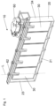
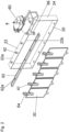
- FIGS 1 and 2 illustrate an embodiment of a grille shutter assembly 10 comprising a grille frame 20 with an opening 25 and at least one lamella 30 extending across at least a portion of the opening 25.
- the grille frame 20 comprises a first side 21 and a second side 22, the first side 21 and the second side 22 being two opposite sides of the grille frame 20.
- the grille frame 20 comprises a third side 23 and a fourth side 24, the third side 23 and the fourth side 24 each connecting the first side 21 and the second side 22 and further being as well two opposite sides of the grille frame 20.
- the grille frame 20 can have a rectangular appearance.
- the second side 22 has a side 22a facing away from the opening 25 and a side 22b facing towards the opening. Same applies for the first side 21, the third side 23 and the fourth side 24.
- the lamella 30 is movably mounted relative to the opening 25 of the grille frame 20 between an open position, in which air is allowed to flow through the opening 25, and a closed position, in which airflow through the opening 25 is restricted (see fig. 1 ). To move between the open position and the closed position, the lamella 30 can turn around a longitudinal axis L.
- the lamella 30 comprises a first end 31 and a second end 32.
- the lamella 30 may be of rectangular shape to optimally cover the rectangular opening 25.
- the grille shutter assembly may comprise a plurality of lamellas 30, the lamellas especially being arranged parallel to each other with their longitudinal axis L spaced apart.
- the lamellas 30 are arranged such that the opening 25 is covered to the largest possible extent when the lamellas 30 are in their closed position.
- the plurality of lamellas 30 may be coupled by a coupling bar 62 for simultaneously moving the lamellas 30.
- a coupling pin 64 may be attached on top of the C-shaped arm 34 which engages in a hole 62a of the coupling bar 62.
- An actuator 60 may be attached to the grille frame 20, the actuator 60 being connected to the coupling bar 62 by means of a transmission 66 to move the coupling bar 62 and thereby moving the lamellas 30 from the open position to the closed position or vice versa.
- a mounting pin 33 is arranged at the first end 31 of the lamella 30, and a C-shaped arm 34 is arranged at the second end 32 of the lamella.
- the mounting pin 33 is removably attached to the grille frame 20 on the first side 21 of the grille frame 20.
- the mounting pin 33 may be placed in a hole 26 arranged in the first side 21 of the grille frame 20.
- the C-shaped arm is removably attached by means of a coupling link 40 to the grille frame 20 on the second side 22 of the grille frame 20.
- the coupling link 40 comprises a receptacle opening 41 and a protrusion 42 being formed to be placed in the receptacle opening 41.
- the receptacle opening 41 may be arranged on the C-shaped arm 34, and the protrusion 42 may be arranged on the second side 22 of the grille frame 20, preferably on the side 22a of the second side 22 facing away of the opening 25.
- the coupling link 40 may comprise a locking assembly 50.
- the locking assembly 50 may comprise a locking projection 51, the locking projection 51 being arranged either in the receptacle opening 41 or on the protrusion 42.
- the locking assembly 50 may in addition or alternatively comprise a snap-in hole 52, the snap-in hole 52 being arranged either at or in the receptacle opening 41 or in the protrusion 42.
- the protrusion 42 may be of cylindrical shape (see figures 3 and 4 , 6 and 7 , or 10 and 11 ) or of spherical shape (see figures 8 and 9 ).
- the protrusion 42 may be of cylindrical shape.
- the receptacle opening 41 may be of cylindrical shape.
- the receptacle opening 41 may comprise a locking projection 51, for example in the form of a circumferential rim.
- the protrusion 42 may comprise a snap-in-hole 52, for example in the form of a circumferential channel.
- the protrusion 42 of this coupling link 40 differs from the protrusion 42 of the first embodiment in that a bushing 43 is arranged on a pin 44, the pin being attached to the side 22a facing away from the opening 25 of the second side 22 of the grille frame 20.
- the snap-in-hole 52 in this case is arranged at the bushing 43.
- the protrusion 42 may be of spherical shape.
- the receptacle opening 41 may be of spherical shape or mushroom-shaped.
- the protrusion 42 in this case itself may form the locking projection 51.
- the receptacle opening 41 in this case itself may form the snap-in-hole 52.
- the protrusion 42 may comprise several, for example four, longitudinal ribs 45.
- the receptacle opening 41 may be of cylindrical shape.
- the protrusion 42 may comprise a locking projection 51, for example in the form of an outward extending projection 45a at the free end of each of the ribs 45.
- the protrusion 42 may have a longer length than the receptacle opening 41, which might be a through-hole, and a snap-in connection may be provided when the outward extending projections 42 protrude from the receptacle opening 41.
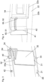
- the lamella For mounting the lamella 30 in the grille frame 20 the lamella can be moved sideways in the opening 25 of the grille frame 20 (see fig. 5a ) until the mounting pin 33 is located above the hole 26 of the first side 21 of the grille frame 20 and the C-shaped arm 34 encompasses the second side 22 of the grille frame 20 (see fig. 5b ). Afterwards the lamella 30 can be lowered until the mounting pin 33 is placed in the hole 26 and the protrusion 42 of the second side 22 of the grille frame 20 engages in the receptacle opening 41 of the C-shaped arm 34 (see fig. 5c ). In this position the locking assembly 50 engages to prevent the lamella 30 from being removed inadvertently.
- the C-shaped arm 34 of the lamella 30 therefore allows easy mounting of the lamella 30 without bending of the lamella 30.
Landscapes
- Engineering & Computer Science (AREA)
- Chemical & Material Sciences (AREA)
- Combustion & Propulsion (AREA)
- Transportation (AREA)
- Mechanical Engineering (AREA)
- Specific Sealing Or Ventilating Devices For Doors And Windows (AREA)
- Cooling, Air Intake And Gas Exhaust, And Fuel Tank Arrangements In Propulsion Units (AREA)
- Connection Of Plates (AREA)
Abstract
Description
- The present invention relates to a grille shutter assembly.
-
WO 2014 150143 A1 discloses a grille assembly for a vehicle which includes a grille frame and a plurality of lamellas. The grille frame includes an opening and the plurality of lamellas is mounted directly to the grille frame and extends across at least a portion of the opening. The lamellas are movable relative to the grille frame between an open position in which air is allowed to flow through the opening and a closed position in which airflow through the opening is restricted. - Known lamellas comprise two pins being arranged on opposite ends of the lamellas and extending in opposite directions to engage in holes arranged on two opposite sides of the grille frame. To mount the lamella in the grille frame, in these cases the lamella has to be bent which might lead in deformation or damage of the lamella.
- It is one task of one embodiment of the present disclosure to provide a grille shutter assembly, especially for a vehicle, the lamellas of which can easily be mounted or changed in case of defect.
- The task is solved by a grille shutter assembly comprising the features specified in claim 1.
- Advantageous embodiments are the subject of the dependent claims.
- According to an embodiment of the present invention, a grille shutter assembly, especially for use in a vehicle, comprises a grille frame with an opening and at least one lamella extending across at least a portion of the opening, the lamella being movably mounted relative to the opening of the grille frame between an open position and a closed position, the lamella comprising a first end and a second end, wherein a mounting pin is arranged at the first end and a C-shaped arm is arranged at the second end, and wherein the mounting pin is removably attached to the grille frame on a first side of the grille frame and the C-shaped arm is removably attached by means of a coupling link to the grille frame on a second side of the grille frame, the first side and the second side being two opposite sides of the grille frame.
- In the open position air is allowed to flow through the opening and in the closed position airflow through the opening is restricted.
- The C-shaped arm of the lamella allows mounting the lamella onto the frame without the use of any additional parts. Especially, the C-shaped arm allows mounting the lamella onto the frame without to deform the lamella.
- According to an embodiment of the invention the grille shutter assembly comprises a plurality of lamellas. When using a plurality of lamellas, each of the lamella might have a smaller surface and therefore the forces, for example of the airflow, acting on each of the lamellas are smaller.
- According to a further embodiment of the invention the plurality of lamellas is coupled by a coupling bar for simultaneously moving the lamellas. Use of such a coupling bar facilitates moving the lamellas.
- According to a further embodiment of the invention the mounting pin is placed in a hole arranged in the first side of the grille frame. Placing a pin in a hole enables easy mounting of the lamella.
- According to a preferred embodiment of the invention the coupling link comprises a receptacle opening and a protrusion being formed to be placed in the receptacle opening. Such kind of coupling link enables easy mounting of the lamella.
- According to a further embodiment of the invention the protrusion is of cylindrical shape or of spherical shape or mushroom-shaped. A protrusion of cylindrical shape enables good guidance of the lamella. A protrusion of spherical shape or mushroom-shaped enables good tolerance compensation.
- According to a further embodiment of the invention the receptacle opening is arranged on the C-shaped arm and the protrusion is arranged on the second side of the grille frame.
- According to a further preferred embodiment of the invention the protrusion is arranged on a side of the second side facing away from the opening of the grille frame. Especially in combination with the C-shaped arm this arrangement of the protrusion allows easy mounting of the lamella without bending of the lamella by moving the lamella sideways in the opening until the mounting pin is located above the hole of the first side of the grille frame and the C-shaped arm encompasses the second side of the grille frame and afterwards lowering the lamella until the mounting pin is placed in the hole and the protrusion engages in the receptacle opening.
- The pin which is placed in the hole and the protrusion which is arranged within the receptacle allow a mounting of the lamella such that the lamella can rotate around the axis of the pin and the protrusion.
- According to a further preferred embodiment of the invention the coupling link comprises a locking assembly. Such locking assembly prevents the lamella from inadvertently being removed from the frame.
- According to an embodiment of the invention the locking assembly comprises a locking projection, the locking projection being arranged either in the receptacle opening or on the protrusion. A locking projection is easy to manufacture and can provide secure fixation.
- According to an embodiment of the invention the locking assembly comprises a snap-in hole, the snap-in hole being arranged either at or in the receptacle opening or in the protrusion. A snap-in hole is easy to manufacture and can provide secure fixation.
- The present invention is described in detail with reference to the drawings attached wherein
- Figure 1
- is a perspective view of a grille shutter assembly according to an embodiment of the present invention,
- Figure 2
- is an exploded view of the grille shutter assembly according to
fig. 1 , - Figure 3
- is an enlarged view of a lamella of the grille shutter assembly according to
fig. 1 , - Figure 4
- is a cross sectional view of a first embodiment of a coupling link of the lamella according to
fig. 3 , - Figure 5a
- is a first view of the process of mounting the lamella in the grille frame of the grille shutter assembly according to
fig. 1 , in which the lamella is moved sideways towards the grille frame, - Figure 5b
- is a second view of the process of mounting the lamella in the grille frame of the grille shutter assembly according to
fig. 1 , in which the lamella reached a position within the grille frame, - Figure 5c
- is a third view of the process of mounting the lamella in the grille frame of the grille shutter assembly according to
fig. 1 , in which the lamella was lowered and is finally mounted in the grille frame, - Figure 6
- is a cross sectional view of a second embodiment of a coupling link for the lamella according to
fig. 3 , - Figure 7
- is an exploded view of a lamella comprising the coupling link according to
fig. 6 , - Figure 8
- is a cross sectional view of a third embodiment of a coupling link for the lamella according to
fig. 3 , - Figure 9
- is an exploded view of a lamella comprising the coupling link according to
fig. 8 , - Figure 10
- is a cross sectional view of a fourth embodiment of a coupling link for the lamella according to
fig. 3 , and - Figure 11
- is a perspective view of a lamella comprising the coupling link according to
fig. 10 . - The figures show different views of different components and embodiments of the present invention. Identical or similar parts are labelled with identical reference numbers in all figures. For clarity reasons not all reference numbers are included in all figures.
-
Figures 1 and2 illustrate an embodiment of agrille shutter assembly 10 comprising agrille frame 20 with an opening 25 and at least onelamella 30 extending across at least a portion of the opening 25. Thegrille frame 20 comprises afirst side 21 and asecond side 22, thefirst side 21 and thesecond side 22 being two opposite sides of thegrille frame 20. Further, thegrille frame 20 comprises athird side 23 and afourth side 24, thethird side 23 and thefourth side 24 each connecting thefirst side 21 and thesecond side 22 and further being as well two opposite sides of thegrille frame 20. Especially, thegrille frame 20 can have a rectangular appearance. Thesecond side 22 has aside 22a facing away from the opening 25 and aside 22b facing towards the opening. Same applies for thefirst side 21, thethird side 23 and thefourth side 24. - The
lamella 30 is movably mounted relative to the opening 25 of thegrille frame 20 between an open position, in which air is allowed to flow through the opening 25, and a closed position, in which airflow through the opening 25 is restricted (seefig. 1 ). To move between the open position and the closed position, thelamella 30 can turn around a longitudinal axis L. - The
lamella 30 comprises afirst end 31 and asecond end 32. Thelamella 30 may be of rectangular shape to optimally cover the rectangular opening 25. In an embodiment, the grille shutter assembly may comprise a plurality oflamellas 30, the lamellas especially being arranged parallel to each other with their longitudinal axis L spaced apart. In a preferred embodiment, thelamellas 30 are arranged such that the opening 25 is covered to the largest possible extent when thelamellas 30 are in their closed position. - The plurality of
lamellas 30 may be coupled by acoupling bar 62 for simultaneously moving thelamellas 30. For coupling thecoupling bar 62 to thelamellas 30, acoupling pin 64 may be attached on top of the C-shapedarm 34 which engages in ahole 62a of thecoupling bar 62. Anactuator 60 may be attached to thegrille frame 20, theactuator 60 being connected to thecoupling bar 62 by means of atransmission 66 to move thecoupling bar 62 and thereby moving thelamellas 30 from the open position to the closed position or vice versa. - A mounting
pin 33 is arranged at thefirst end 31 of thelamella 30, and a C-shapedarm 34 is arranged at thesecond end 32 of the lamella. The mountingpin 33 is removably attached to thegrille frame 20 on thefirst side 21 of thegrille frame 20. For example, the mountingpin 33 may be placed in ahole 26 arranged in thefirst side 21 of thegrille frame 20. - The C-shaped arm is removably attached by means of a coupling link 40 to the
grille frame 20 on thesecond side 22 of thegrille frame 20. In an embodiment, the coupling link 40 comprises areceptacle opening 41 and aprotrusion 42 being formed to be placed in thereceptacle opening 41. Thereceptacle opening 41 may be arranged on the C-shapedarm 34, and theprotrusion 42 may be arranged on thesecond side 22 of thegrille frame 20, preferably on theside 22a of thesecond side 22 facing away of the opening 25. - In an embodiment, the coupling link 40 may comprise a locking assembly 50. The locking assembly 50 may comprise a locking
projection 51, the lockingprojection 51 being arranged either in thereceptacle opening 41 or on theprotrusion 42. The locking assembly 50 may in addition or alternatively comprise a snap-inhole 52, the snap-inhole 52 being arranged either at or in thereceptacle opening 41 or in theprotrusion 42. - Different embodiments of the coupling link 40 are illustrated in
figures 3 and 4 (first embodiment), 6 and 7 (second embodiment), 8 and 9 (third embodiment), or 10 and 11 (fourth embodiment). Theprotrusion 42 may be of cylindrical shape (seefigures 3 and 4 ,6 and 7 , or10 and 11 ) or of spherical shape (seefigures 8 and 9 ). - In the first embodiment of the coupling link 40 (see
figures 3 and 4 ), theprotrusion 42 may be of cylindrical shape. Respectively, thereceptacle opening 41 may be of cylindrical shape. Thereceptacle opening 41 may comprise a lockingprojection 51, for example in the form of a circumferential rim. Theprotrusion 42 may comprise a snap-in-hole 52, for example in the form of a circumferential channel. - In the second embodiment of the coupling link 40 (see
figures 6 and 7 ), theprotrusion 42 of this coupling link 40 differs from theprotrusion 42 of the first embodiment in that abushing 43 is arranged on apin 44, the pin being attached to theside 22a facing away from the opening 25 of thesecond side 22 of thegrille frame 20. The snap-in-hole 52 in this case is arranged at thebushing 43. - In the third embodiment of the coupling link 40 (see
figures 8 and 9 ), theprotrusion 42 may be of spherical shape. Respectively, thereceptacle opening 41 may be of spherical shape or mushroom-shaped. Theprotrusion 42 in this case itself may form the lockingprojection 51. Thereceptacle opening 41 in this case itself may form the snap-in-hole 52. - In the fourth embodiment of the coupling link 40 (see
figures 10 and 11 ), theprotrusion 42 may comprise several, for example four,longitudinal ribs 45. Thereceptacle opening 41 may be of cylindrical shape. Theprotrusion 42 may comprise a lockingprojection 51, for example in the form of an outward extendingprojection 45a at the free end of each of theribs 45. Theprotrusion 42 may have a longer length than thereceptacle opening 41, which might be a through-hole, and a snap-in connection may be provided when the outward extendingprojections 42 protrude from thereceptacle opening 41. - For mounting the
lamella 30 in thegrille frame 20 the lamella can be moved sideways in the opening 25 of the grille frame 20 (seefig. 5a ) until the mountingpin 33 is located above thehole 26 of thefirst side 21 of thegrille frame 20 and the C-shapedarm 34 encompasses thesecond side 22 of the grille frame 20 (seefig. 5b ). Afterwards thelamella 30 can be lowered until the mountingpin 33 is placed in thehole 26 and theprotrusion 42 of thesecond side 22 of thegrille frame 20 engages in thereceptacle opening 41 of the C-shaped arm 34 (seefig. 5c ). In this position the locking assembly 50 engages to prevent thelamella 30 from being removed inadvertently. The C-shapedarm 34 of thelamella 30 therefore allows easy mounting of thelamella 30 without bending of thelamella 30. -
- 10
- grille frame assembly
- 20
- grille frame
- 21
- first side
- 22
- second side
- 22a
- side facing away from the opening
- 22b
- side facing towards the opening
- 23
- third side
- 24
- fourth side
- 25
- opening
- 30
- lamella
- 31
- first end
- 32
- second end
- 33
- mounting pin
- 34
- C-shaped arm
- 40
- coupling link
- 41
- receptacle opening
- 42
- protrusion
- 43
- bushing
- 44
- pin
- 45
- rib
- 45a
- projection
- 50
- locking assembly
- 51
- locking projection
- 52
- snap-in hole
- 60
- actuator
- 62
- coupling bar
- 62a
- hole
- 64
- coupling pin
- 66
- transmission
- L
- longitudinal axis
Claims (11)
- Grille shutter assembly (10) comprising a grille frame with (20) an opening (25) and at least one lamella (30) extending across at least a portion of the opening (25), the lamella (30) being movably mounted relative to the opening (25) of the grille frame (20) between an open position and a closed position, the lamella (30) comprising a first end (31) and a second end (32),
characterized in that a mounting pin (33) is arranged at the first end (31) and a C-shaped arm (34) is arranged at the second end (32), and that the mounting pin (33) is removably attached to the grille frame (20) on a first side (21) of the grille frame (20) and the C-shaped arm (34) is removably attached by means of a coupling link (40) to the grille frame (20) on a second side (22) of the grille frame (20), the first side (21) and the second side (22) being two opposite sides of the grille frame (20) . - Grille shutter assembly according to claim 1,
characterized in that the grille shutter assembly (10) comprises a plurality of lamellas (30). - Grille shutter assembly according to claim 2,
characterized in that the plurality of lamellas (30) is coupled by a coupling bar (62) for simultaneously moving the lamellas (30). - Grille shutter assembly according to one of the preceding claims,
characterized in that the mounting pin (33) is placed in a hole (26) arranged in the first side (21) of the grille frame (20). - Grille shutter assembly according to one of the preceding claims,
characterized in that the coupling link (409 comprises a receptacle opening (41) and a protrusion (42) being formed to be placed in the receptacle opening (41). - Grille shutter assembly according to claim 5,
characterized in that the protrusion (42) is of cylindrical shape or of spherical shape or mushroom-shaped. - Grille shutter assembly according to claim 5 or 6,
characterized in that the receptacle opening (41) is arranged on the C-shaped arm (34) and the protrusion (42) is arranged on the second side (22) of the grille frame (20). - Grille shutter assembly according to claim 7,
characterized in that the protrusion (42) is arranged on a side (22a) of the second side (22) facing away from the opening (25) of the grille frame (20). - Grille shutter assembly according to one of the preceding claims,
characterized in that the coupling link (40) comprises a locking assembly (50). - Grille shutter assembly according to claim 9,
characterized in that the locking assembly (50) comprises a locking projection (51), the locking projection (51) being arranged either in the receptacle opening (41) or on the protrusion (42) . - Grille shutter assembly according to claim 9 or 10, characterized in that the locking assembly (50) comprises a snap-in hole (52), the snap-in hole (52) being arranged either at or in the receptacle opening (41) or in the protrusion (42).
Priority Applications (2)
| Application Number | Priority Date | Filing Date | Title |
|---|---|---|---|
| EP23191532.3A EP4509341B1 (en) | 2023-08-15 | 2023-08-15 | Grille shutter assembly |
| ES23191532T ES3063060T3 (en) | 2023-08-15 | 2023-08-15 | Grille shutter assembly |
Applications Claiming Priority (1)
| Application Number | Priority Date | Filing Date | Title |
|---|---|---|---|
| EP23191532.3A EP4509341B1 (en) | 2023-08-15 | 2023-08-15 | Grille shutter assembly |
Publications (2)
| Publication Number | Publication Date |
|---|---|
| EP4509341A1 true EP4509341A1 (en) | 2025-02-19 |
| EP4509341B1 EP4509341B1 (en) | 2025-12-03 |
Family
ID=87575874
Family Applications (1)
| Application Number | Title | Priority Date | Filing Date |
|---|---|---|---|
| EP23191532.3A Active EP4509341B1 (en) | 2023-08-15 | 2023-08-15 | Grille shutter assembly |
Country Status (2)
| Country | Link |
|---|---|
| EP (1) | EP4509341B1 (en) |
| ES (1) | ES3063060T3 (en) |
Citations (4)
| Publication number | Priority date | Publication date | Assignee | Title |
|---|---|---|---|---|
| WO2014150143A1 (en) | 2013-03-15 | 2014-09-25 | Srg Global, Inc. | Grille shutter assembly |
| US20170248066A1 (en) * | 2016-02-29 | 2017-08-31 | Montaplast of North America, Inc. | Active grille shutter and shutter subassembly for use with active grill shutters |
| DE102021127798A1 (en) * | 2020-10-30 | 2022-05-05 | Geiger Automotive Gmbh | Gear flap with position detection |
| DE102021133573B3 (en) * | 2021-12-17 | 2023-01-26 | Dr. Ing. H.C. F. Porsche Aktiengesellschaft | Slat device, a motor vehicle and a method for operating such a slat device |
-
2023
- 2023-08-15 EP EP23191532.3A patent/EP4509341B1/en active Active
- 2023-08-15 ES ES23191532T patent/ES3063060T3/en active Active
Patent Citations (4)
| Publication number | Priority date | Publication date | Assignee | Title |
|---|---|---|---|---|
| WO2014150143A1 (en) | 2013-03-15 | 2014-09-25 | Srg Global, Inc. | Grille shutter assembly |
| US20170248066A1 (en) * | 2016-02-29 | 2017-08-31 | Montaplast of North America, Inc. | Active grille shutter and shutter subassembly for use with active grill shutters |
| DE102021127798A1 (en) * | 2020-10-30 | 2022-05-05 | Geiger Automotive Gmbh | Gear flap with position detection |
| DE102021133573B3 (en) * | 2021-12-17 | 2023-01-26 | Dr. Ing. H.C. F. Porsche Aktiengesellschaft | Slat device, a motor vehicle and a method for operating such a slat device |
Also Published As
| Publication number | Publication date |
|---|---|
| ES3063060T3 (en) | 2026-04-15 |
| EP4509341B1 (en) | 2025-12-03 |
Similar Documents
| Publication | Publication Date | Title |
|---|---|---|
| DE102017213744B3 (en) | Pneumatic valve | |
| EP2371591B1 (en) | Ventilation device | |
| EP2810801B1 (en) | Operating device for an air vent and air vent | |
| DE102016209490A1 (en) | Tool Storage device | |
| DE102008028978B4 (en) | Sensor arrangement for a motor vehicle | |
| DE102007034004A1 (en) | Method for producing a lever of a connector with lever attachment | |
| EP4509341B1 (en) | Grille shutter assembly | |
| EP3078794B1 (en) | Pivoting device for a motor vehicle with easy-to-install and also safe pivot bearing | |
| DE102014117062A1 (en) | Spring terminal | |
| DE102016108356A1 (en) | Air vents for a motor vehicle | |
| DE10356532B4 (en) | storage compartment | |
| DE10119910C1 (en) | casing | |
| DE60124353T2 (en) | Air damper for a vehicle glove box | |
| EP1063125B1 (en) | Actuator for a motor vehicle | |
| DE19919529A1 (en) | Actuating drive, for rear view mirror of motor vehicle, for example, has one-piece friction and adjusting unit serving as connection between first and second element of drive and is tension loaded | |
| DE102011075960B4 (en) | Automotive interior light | |
| DE102021116131B4 (en) | Camera assembly arrangement for a vehicle rear view fairing | |
| WO2012035130A1 (en) | Display unit having a projection screen for a head-up display | |
| EP0983900A2 (en) | Exterior vehicle mirror | |
| DE102017002386A1 (en) | Battery carrier for a commercial vehicle | |
| EP3211324A1 (en) | Bearing bush for a household appliance with a spring element, comprising a cover for covering an insertion opening, assembly and household appliance | |
| KR200467638Y1 (en) | Door hinge assembly and cabinet having the assembly | |
| WO2024156487A1 (en) | Holding device, electronic arrangement and method for producing an electronic arrangement for a motor vehicle | |
| DE102004028422A1 (en) | Headlight assembly with vertical headlight adjustment device | |
| DE102006052832B4 (en) | Meander spring for arrangement between two elements |
Legal Events
| Date | Code | Title | Description |
|---|---|---|---|
| PUAI | Public reference made under article 153(3) epc to a published international application that has entered the european phase |
Free format text: ORIGINAL CODE: 0009012 |
|
| STAA | Information on the status of an ep patent application or granted ep patent |
Free format text: STATUS: THE APPLICATION HAS BEEN PUBLISHED |
|
| AK | Designated contracting states |
Kind code of ref document: A1 Designated state(s): AL AT BE BG CH CY CZ DE DK EE ES FI FR GB GR HR HU IE IS IT LI LT LU LV MC ME MK MT NL NO PL PT RO RS SE SI SK SM TR |
|
| STAA | Information on the status of an ep patent application or granted ep patent |
Free format text: STATUS: REQUEST FOR EXAMINATION WAS MADE |
|
| RAP3 | Party data changed (applicant data changed or rights of an application transferred) |
Owner name: MOTHERSON INNOVATIONS COMPANY LIMITED |
|
| 17P | Request for examination filed |
Effective date: 20250324 |
|
| GRAP | Despatch of communication of intention to grant a patent |
Free format text: ORIGINAL CODE: EPIDOSNIGR1 |
|
| STAA | Information on the status of an ep patent application or granted ep patent |
Free format text: STATUS: GRANT OF PATENT IS INTENDED |
|
| INTG | Intention to grant announced |
Effective date: 20250602 |
|
| GRAS | Grant fee paid |
Free format text: ORIGINAL CODE: EPIDOSNIGR3 |
|
| GRAA | (expected) grant |
Free format text: ORIGINAL CODE: 0009210 |
|
| STAA | Information on the status of an ep patent application or granted ep patent |
Free format text: STATUS: THE PATENT HAS BEEN GRANTED |
|
| AK | Designated contracting states |
Kind code of ref document: B1 Designated state(s): AL AT BE BG CH CY CZ DE DK EE ES FI FR GB GR HR HU IE IS IT LI LT LU LV MC ME MK MT NL NO PL PT RO RS SE SI SK SM TR |
|
| REG | Reference to a national code |
Ref country code: CH Ref legal event code: F10 Free format text: ST27 STATUS EVENT CODE: U-0-0-F10-F00 (AS PROVIDED BY THE NATIONAL OFFICE) Effective date: 20251203 Ref country code: GB Ref legal event code: FG4D |
|
| REG | Reference to a national code |
Ref country code: DE Ref legal event code: R096 Ref document number: 602023009199 Country of ref document: DE |
|
| REG | Reference to a national code |
Ref country code: IE Ref legal event code: FG4D |
|
| P01 | Opt-out of the competence of the unified patent court (upc) registered |
Free format text: CASE NUMBER: UPC_APP_0014742_4509341/2025 Effective date: 20251126 |
|
| REG | Reference to a national code |
Ref country code: CH Ref legal event code: W10 Free format text: ST27 STATUS EVENT CODE: U-0-0-W10-W00 (AS PROVIDED BY THE NATIONAL OFFICE) Effective date: 20260225 |
|
| RAP4 | Party data changed (patent owner data changed or rights of a patent transferred) |
Owner name: MOTHERSON INNOVATIONS COMPANY LIMITED |
|
| REG | Reference to a national code |
Ref country code: NL Ref legal event code: MP Effective date: 20251203 |
|
| REG | Reference to a national code |
Ref country code: LT Ref legal event code: MG9D |
|
| PG25 | Lapsed in a contracting state [announced via postgrant information from national office to epo] |
Ref country code: NO Free format text: LAPSE BECAUSE OF FAILURE TO SUBMIT A TRANSLATION OF THE DESCRIPTION OR TO PAY THE FEE WITHIN THE PRESCRIBED TIME-LIMIT Effective date: 20260303 |
|
| PG25 | Lapsed in a contracting state [announced via postgrant information from national office to epo] |
Ref country code: FI Free format text: LAPSE BECAUSE OF FAILURE TO SUBMIT A TRANSLATION OF THE DESCRIPTION OR TO PAY THE FEE WITHIN THE PRESCRIBED TIME-LIMIT Effective date: 20251203 Ref country code: HR Free format text: LAPSE BECAUSE OF FAILURE TO SUBMIT A TRANSLATION OF THE DESCRIPTION OR TO PAY THE FEE WITHIN THE PRESCRIBED TIME-LIMIT Effective date: 20251203 |
|
| REG | Reference to a national code |
Ref country code: ES Ref legal event code: FG2A Ref document number: 3063060 Country of ref document: ES Kind code of ref document: T3 Effective date: 20260415 |
|
| PG25 | Lapsed in a contracting state [announced via postgrant information from national office to epo] |
Ref country code: RS Free format text: LAPSE BECAUSE OF FAILURE TO SUBMIT A TRANSLATION OF THE DESCRIPTION OR TO PAY THE FEE WITHIN THE PRESCRIBED TIME-LIMIT Effective date: 20260303 |
|
| PG25 | Lapsed in a contracting state [announced via postgrant information from national office to epo] |
Ref country code: PL Free format text: LAPSE BECAUSE OF FAILURE TO SUBMIT A TRANSLATION OF THE DESCRIPTION OR TO PAY THE FEE WITHIN THE PRESCRIBED TIME-LIMIT Effective date: 20251203 |
|
| PG25 | Lapsed in a contracting state [announced via postgrant information from national office to epo] |
Ref country code: LV Free format text: LAPSE BECAUSE OF FAILURE TO SUBMIT A TRANSLATION OF THE DESCRIPTION OR TO PAY THE FEE WITHIN THE PRESCRIBED TIME-LIMIT Effective date: 20251203 |
|
| PG25 | Lapsed in a contracting state [announced via postgrant information from national office to epo] |
Ref country code: BG Free format text: LAPSE BECAUSE OF FAILURE TO SUBMIT A TRANSLATION OF THE DESCRIPTION OR TO PAY THE FEE WITHIN THE PRESCRIBED TIME-LIMIT Effective date: 20251203 |