EP4509322A2 - Printer - Google Patents
Printer Download PDFInfo
- Publication number
- EP4509322A2 EP4509322A2 EP24220214.1A EP24220214A EP4509322A2 EP 4509322 A2 EP4509322 A2 EP 4509322A2 EP 24220214 A EP24220214 A EP 24220214A EP 4509322 A2 EP4509322 A2 EP 4509322A2
- Authority
- EP
- European Patent Office
- Prior art keywords
- printer
- printer cover
- surface portion
- cover
- roll body
- Prior art date
- Legal status (The legal status is an assumption and is not a legal conclusion. Google has not performed a legal analysis and makes no representation as to the accuracy of the status listed.)
- Pending
Links
Images









Classifications
-
- B—PERFORMING OPERATIONS; TRANSPORTING
- B41—PRINTING; LINING MACHINES; TYPEWRITERS; STAMPS
- B41J—TYPEWRITERS; SELECTIVE PRINTING MECHANISMS, i.e. MECHANISMS PRINTING OTHERWISE THAN FROM A FORME; CORRECTION OF TYPOGRAPHICAL ERRORS
- B41J11/00—Devices or arrangements of selective printing mechanisms, e.g. ink-jet printers or thermal printers, for supporting or handling copy material in sheet or web form
- B41J11/02—Platens
- B41J11/04—Roller platens
-
- B—PERFORMING OPERATIONS; TRANSPORTING
- B41—PRINTING; LINING MACHINES; TYPEWRITERS; STAMPS
- B41J—TYPEWRITERS; SELECTIVE PRINTING MECHANISMS, i.e. MECHANISMS PRINTING OTHERWISE THAN FROM A FORME; CORRECTION OF TYPOGRAPHICAL ERRORS
- B41J15/00—Devices or arrangements of selective printing mechanisms, e.g. ink-jet printers or thermal printers, specially adapted for supporting or handling copy material in continuous form, e.g. webs
- B41J15/04—Supporting, feeding, or guiding devices; Mountings for web rolls or spindles
-
- B—PERFORMING OPERATIONS; TRANSPORTING
- B41—PRINTING; LINING MACHINES; TYPEWRITERS; STAMPS
- B41J—TYPEWRITERS; SELECTIVE PRINTING MECHANISMS, i.e. MECHANISMS PRINTING OTHERWISE THAN FROM A FORME; CORRECTION OF TYPOGRAPHICAL ERRORS
- B41J15/00—Devices or arrangements of selective printing mechanisms, e.g. ink-jet printers or thermal printers, specially adapted for supporting or handling copy material in continuous form, e.g. webs
- B41J15/04—Supporting, feeding, or guiding devices; Mountings for web rolls or spindles
- B41J15/042—Supporting, feeding, or guiding devices; Mountings for web rolls or spindles for loading rolled-up continuous copy material into printers, e.g. for replacing a used-up paper roll; Point-of-sale printers with openable casings allowing access to the rolled-up continuous copy material
-
- B—PERFORMING OPERATIONS; TRANSPORTING
- B41—PRINTING; LINING MACHINES; TYPEWRITERS; STAMPS
- B41J—TYPEWRITERS; SELECTIVE PRINTING MECHANISMS, i.e. MECHANISMS PRINTING OTHERWISE THAN FROM A FORME; CORRECTION OF TYPOGRAPHICAL ERRORS
- B41J2/00—Typewriters or selective printing mechanisms characterised by the printing or marking process for which they are designed
- B41J2/315—Typewriters or selective printing mechanisms characterised by the printing or marking process for which they are designed characterised by selective application of heat to a heat sensitive printing or impression-transfer material
- B41J2/32—Typewriters or selective printing mechanisms characterised by the printing or marking process for which they are designed characterised by selective application of heat to a heat sensitive printing or impression-transfer material using thermal heads
-
- B—PERFORMING OPERATIONS; TRANSPORTING
- B41—PRINTING; LINING MACHINES; TYPEWRITERS; STAMPS
- B41J—TYPEWRITERS; SELECTIVE PRINTING MECHANISMS, i.e. MECHANISMS PRINTING OTHERWISE THAN FROM A FORME; CORRECTION OF TYPOGRAPHICAL ERRORS
- B41J29/00—Details of, or accessories for, typewriters or selective printing mechanisms not otherwise provided for
- B41J29/12—Guards, shields or dust excluders
- B41J29/13—Cases or covers
Definitions
- the present invention relates to a printer that prints information on a print medium.
- thermal printers that print on a print medium by thermal transfer are known (hereinafter simply referred to as "printers").
- a print medium is held in a pressurized state between a thermal head and a platen roller, and heating elements on the thermal head are selectively heated to print.
- the platen roller is attached to an openable printer cover provided at the upper part of a roll body accommodating chamber (e.g., Japanese Laid-open Patent publication No. 2014-188708 and Japanese unexamined Utility Model Application Publication No. H6-52274 ).
- a roll body accommodating chamber e.g., Japanese Laid-open Patent publication No. 2014-188708 and Japanese unexamined Utility Model Application Publication No. H6-52274 .
- the printer cover is opened about a hinge located substantially at the upper end of the rear of the body, but it does not fully open the roll body accommodating chamber. The user cannot easily set in or remove a roll body from the roll body accommodating chamber.
- the printer cover is opened about a hinge located substantially at the lower end of the rear of the body.
- the printer cover is opened until a projecting part, provided at the tip of a guide part integrated with the printer cover, abuts on a stopper provided at the body of the printer.
- the maximum open angle of the printer cover at which the projecting part abuts on the stopper is about 45 degrees.
- the printer cover even when the printer cover is fully open, it still covers at least the upper half of the roll body accommodating chamber, preventing the user from easily setting or removing the roll body from the roll body accommodating chamber.
- An object of the present invention is to provide a printer with a great maximum open angle by which a printer cover is opened.
- An embodiment of the present invention is a printer including: a body case that includes a placement surface for the printer and an accommodating chamber for accommodating a roll body into which a belt-shaped print medium are wound; a printer cover configured to open and close the accommodating chamber; a platen roller that is attached to the printer cover and configured to convey the belt-shaped print medium drawn out of the roll body; and a hinge that includes a hinge shaft and is configured to couple the printer cover with the body case so that the printer cover is swingable about the hinge shaft relative to the body case.
- the printer cover comprises an upper surface portion and an inclined surface portion, the inclined surface portion being provided between the hinge shaft and the upper surface portion and inclined relative to the placement surface.
- H1 ⁇ H2 is established where H1 is defined as a height from the placement surface to the hinge shaft and H2 is defined as a height from the placement surface to a highest position from the hinge shaft to the upper surface portion.
- An embodiment of the present invention increases the maximum open angle by which the printer cover is opened.
- FIG. 1A is a perspective view of the printer 1 according to the embodiment showing its front, top, and left faces with the printer cover 3 closed.
- FIG. 1B is a perspective view of the printer 1 according to the embodiment showing its front, top, and left faces with the printer cover 3 open.
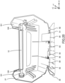
- FIG. 2 is a perspective view of the printer 1 according to the embodiment of the present invention showing its rear, upper, and left faces.
- the printer 1 includes a body case 2, a printer cover 3, a display panel 4, a platen roller 10, and a thermal head 28.
- the bottom surface of the printer 1 is substantially rectangular.
- a direction along its long side is defined as a front-rear direction. That is, it is defined that a side with the display panel 4 is the front (-Y) and the opposite printer cover side is the rear (+Y).
- the right side (-X), the left side (+X), the top side (+Z), and the bottom side (-Z) are defined relative to the front-rear direction.
- the right (-X) or left (+X) direction is referred to as the lateral direction
- the top (+Z) or bottom (-Z) direction is referred to as the top-bottom direction.
- the directions may be defined on XYZ axes.
- the printer 1 may include a roll body accommodating chamber 9 for accommodating a roll body, which has a sheet of paper wound around to be printed.
- the body case 2 may include an inner bottom surface 2a (see FIG. 18 ) for the roll body to be placed on.
- the printer cover 3 is a cover that opens or shuts off the inside (e.g., the roll body accommodating chamber 9) of the printer 1.
- a hinge 8, including a hinge shaft 81, is provided at the rear end of the printer cover 3.
- the hinge 8 rotatably supports the printer cover 3 to be rearwardly openable relative to the body case.
- "rearwardly openable” means that the printer cover 3 is opened about the hinge 8 on the rear end side of the printer cover 3.
- the display panel 4 functions as an input/output interface for the user, and is a liquid crystal display panel with the touchscreen function, for example.
- an attachment part 163 is provided at a front inner surface portion 161 of the printer cover 3, which is an inner surface portion opposite to the side where the hinge 8 is.
- the attachment part 163 holds a platen roller 10 to be rotatable in the forward and reverse directions.
- FIG. 18 when the printer cover 3 is closed, the platen roller 10 is disposed behind the thermal head 28.
- the platen roller 10 is conveying means that is mounted on the printer cover 3 and conveys a continuous sheet CP drawn out of a roll body R, which is accommodated in the roll body accommodating chamber 9 while retained by a pair of roll body guides 6.
- the platen roller extends along the width direction of the roll body R.
- the platen roller 10 is mechanically coupled to a stepping motor (not shown) or the like to be driven.
- the roll body R includes a core 7 and the belt-shaped continuous sheet CP wound around the core 7.
- the roll body guides 6 support both side surfaces of the roll body R accommodated in the roll body accommodating chamber 9.
- the center of the roll body guides 6 matches the center of the roll body R.
- the hinge 8 is disposed at a lower position than an axis 6a of the roll body guides 6. Accordingly, the hinge 8 is positioned lower than the axis of the roll body R set in the printer 1 by the roll body guides 6. Thus, the hinge 8 is positioned frontward in the front-rear direction as compared to the case where the hinge 8 is disposed at the identical height to the axis 6a of the roll body guides 6. This reduces the size of the printer 1 in the front-rear direction.
- the thermal head 28 is printing means that prints information such as characters, symbols, graphics, or barcodes on the sheet of the roll body R. As shown in FIG. 18 , when the printer cover 3 is closed, the printing surface of the thermal head 28 faces a feeding path of the sheet and is opposed to the platen roller 10. A plurality of heat elements (not shown) that generate heat when energized are arranged on the printing surface of the thermal head 28 along the width direction of the sheet. The thermal head 28 is connected to a circuit board (not shown) that transmits print signals to the thermal head 28.
- a coil spring 157 as a biasing member is provided for providing biasing force to the thermal head 28.
- the printer cover 3 When the printer cover 3 is closed and printing is carried out, the sheet is held between the platen roller 10 and the thermal head 28 while conveyed by the platen roller 10.
- the thermal head 28 is pressed against the platen roller 10 by the biasing force, generating a head pressure suitable for printing.
- the body case 2 includes the roll body accommodating chamber 9. Around the roll body accommodating chamber 9, the body case 2 covers the lower half of the roll body accommodating chamber 9 on the right and left sides and from behind. As shown in FIG. 3 , the bottom surface of the body case 2 is a placement surface 20 on which the printer 1 is placed for operation.
- a rear surface portion 121 of the body case 2 is inclined to be oriented obliquely downward on the rear side.
- the printer cover 3 covers the upper half of the roll body accommodating chamber on the right and left sides and from behind and above.
- a rear surface portion 123 of the printer cover 3 is inclined to be oriented obliquely upward on the rear side.
- a rear projecting part is formed at the boundary between an upper peripheral part 127 of the rear surface portion 121 of the body case 2 and a lower peripheral part 129 of the rear surface portion 123 of the printer cover 3. Accordingly, the boundary between the upper peripheral part 127 of the rear surface portion 121 of the body case 2 and the lower peripheral part 129 of the rear surface portion 123 of the printer cover 3 is at a position projecting on the rear side of the printer 1.
- a pair of front sides 125a of side surface portions 125 on the right and left sides of the printer cover 3 are inclined downward toward the rear.
- the pair of front sides 125a are positioned farthest from the hinge 8 in the side surface portions 125, which are opposed to and spaced apart from each other in the axial direction of the hinge shaft 81, of the printer cover 3.
- the pair of front sides 125a are inclined toward the hinge 8 side from the open side to the closed side of the printer cover 3. Accordingly, when the printer cover 3 is opened or closed, the side surface portions 125 will not interfere with the body case 2.
- the printer cover 3 can be opened and closed about the axis of the hinge 8 between the closed position shown in FIG. 3 and the open position at the maximum open angle shown in FIG. 9 .
- the maximum open angle refers to the angle at which the printer cover 3 cannot further be rotated by cover-side buffer members 151 that is provided at the rear surface portion 123 of the printer cover 3.
- the cover-side buffer members 151 abut on body-side buffer members 141 provided at the rear surface portion 121 of the body case 2.
- the printer cover 3 includes an upper surface portion 122, an inclined surface portion 124, and a rear surface portion 123.
- the inclined surface portion 124 and the upper surface portion 122 continue in this order, to the side of the rear surface portion 123 opposite to the hinge 8.
- the rear surface portion 123 and the inclined surface portion 124 are connected at an obtuse interior angle (about 135 degrees).
- the inclined surface portion 124 and the upper surface portion 122 are connected at an obtuse interior angle (about 135 degrees).
- An angle between the rear surface portion 123 and the upper surface portion 122 is about 90 degrees.
- the upper surface portion 122, the inclined surface portion 124, and the rear surface portion 123 surround the roll body R accommodated in the roll body accommodating chamber 9. This structure reduces the size of the printer cover 3.
- the inclined surface portion 124 becomes substantially horizontal when the printer cover 3 is opened by the maximum open angle.
- an angle by which the boundary side between the upper surface portion 122 and the rear surface portion 123 abuts on the printer placement surface becomes the maximum open angle.
- the maximum open angle will be less than the maximum open angle of the open printer cover 3 shown in FIG. 9 .
- the inclined surface portion 124 allows for increase of the maximum open angle.
- the printer cover 3 has a two-layer structure comprised of an inner printer cover 36 and an outer printer cover 37 in view of toughness.
- the printer cover 3 is not specified to have such a double structure, and may be comprised of a single member.
- the hinge 8 couples the printer cover 3 to the body case 2 to be capable of being opened and closed. That is, the hinge 8 couples the printer cover 3 with the body case 2 so that the printer cover 3 can swing about the hinge shaft 81 (described later) relative to the body case 2.
- the hinge 8 rotatably couples the upper peripheral part 127 of the rear surface portion 121 of the body case 2 with the lower peripheral part 129 of the rear surface portion 123 of the printer cover 3.
- the hinge 8 extends in the lateral direction of the body case 2. Accordingly, the hinge 8 extends around the boundary between the upper peripheral part 127 of the rear surface portion 121 of the body case 2 and the lower peripheral part 129 of the rear surface portion 123 of the printer cover 3.
- the hinge 8 includes the hinge shaft 81, body-side shaft-supporting long holes 82, inner printer cover-side shaft-supporting round holes 83, outer printer cover-side shaft-supporting round holes 84, and a torsion spring 85.
- the pair of body-side shaft-supporting long holes 82 are provided at the right and left ends near the rear end of the roll body accommodating chamber 9.
- the body-side shaft-supporting long holes 82 have a long axis in the front-rear direction (i.e., Y-axis direction).
- the long axis direction of the body-side shaft-supporting long holes 82 may be slightly displaced from the front-rear direction.
- the pair of inner printer cover-side shaft-supporting round holes 83 are provided at the rear end of the inner printer cover 36.
- the pair of the outer printer cover-side shaft-supporting round holes 84 are provided at the rear end of the outer printer cover 37.
- the hinge shaft 81 is inserted through the pair of inner printer cover-side shaft-supporting round holes 83 and the pair of outer printer cover-side shaft-supporting round holes 84.
- the hinge shaft 81 has its both ends inserted into the pair of body-side shaft-supporting long holes 82.
- the hinge shaft 81 extends in the lateral direction at the upper peripheral part 127 of the rear surface portion 121 of the body case 2. Accordingly, the body-side shaft-supporting long holes 82, the inner printer cover-side shaft-supporting round holes 83, and the outer printer cover-side shaft-supporting round holes 84 are also provided at the upper peripheral part 127 of the rear surface portion 121 of the body case 2.
- the inner printer cover-side shaft-supporting round holes 83 and the outer printer cover-side shaft-supporting round holes 84 of the printer cover 3 are positioned lower than a horizontal boundary line 133 (see FIGS. 3 and 4 ) between the body case 2 and the printer cover 3.
- the inner printer cover 36 and the outer printer cover 37 are integrated by being screwed to each other.
- the inner printer cover 36 and the outer printer cover 37 can rotate about the hinge shaft 81 while being integrated.
- the inner printer cover 36 and the outer printer cover 37 are not screwed, they can separately rotate about the hinge shaft 81.
- FIG. 19 shows the inner printer cover 36 and the outer printer cover 37 integrated by being screwed to each other.
- FIG. 20 shows the inner printer cover 36 and the outer printer cover 37 not being screwed but separated from each other.
- the integrated inner printer cover 36 and outer printer cover 37 slide together in the front-rear direction. That is, when the hinge shaft 81 slides in the front-rear direction, the printer cover 3 slides in the front-rear direction.
- the integrated inner printer cover 36 and outer printer cover 37 can rotate together about the hinge shaft 81. That is, the printer cover 3 can rotate about the hinge shaft 81.
- the torsion spring 85 biases the printer cover 3 to open the closed printer cover 3.
- the body-side shaft-supporting long holes 82 whose long axes are elongated in the front-rear direction allows the shaft of the hinge 8 to slide in the front-rear direction.
- printer cover 3 has an integral structure instead of the double structure comprised of the inner printer cover 36 and the outer printer cover 37, not both the inner printer cover-side shaft-supporting round holes 83 and the outer printer cover-side shaft-supporting round holes 84 are required and one of them will suffice.
- a plurality of body-side buffer members 141 are arranged in the lateral direction on the rear surface portion 121 of the body case 2.
- three body-side buffer members 141 are arranged in the lateral direction on each of the right and left sides of the rear surface portion 121 of the body case 2.
- a plurality of cover-side buffer members 151 are arranged in the lateral direction on the rear surface portion 123 of the printer cover 3.
- three cover-side buffer members 151 are arranged in the lateral direction on each of the right and left sides of the rear surface portion 123 of the printer cover 3.
- the present invention is not limited thereto and a single body-side buffer members and a single cover-side buffer members may be provided.
- the body-side buffer members 141 and the cover-side buffer members 151 are opposed to each other with reference to the hinge 8.
- the body-side buffer members 141 and the cover-side buffer members 151 form pairs at the identical positions in the lateral direction.
- FIG. 5 is an enlarged partial view corresponding to FIG. 4 .
- the body-side buffer members 141 each include a total of five surfaces, i.e., a tip surface 142, an upper surface 143, a lower surface 144, a left surface 145, and a right surface 146.
- the cover-side buffer members 151 each include a total of five surfaces, i.e., a tip surface 152, an upper surface 153, a lower surface 154, a left surface 155, and a right surface 156.
- the printer cover 3 does not interfere with the body case 2.
- the profile PF1 shown in FIG. 12 is a profile of the printer cover 3 at the closed position (where the open angle is zero degrees).
- the roll body R is covered with the body case 2 and the printer cover 3 so that the roll body R set in the printer 1 partially overlaps with the printer cover 3.
- the printer cover 3 partially covers part of the roll body R set in the printer 1 as seen from the rear projection plane irrespective of the open angle of the printer cover 3.
- the printer cover 3 when the printer cover 3 is at the closed position, the printer cover 3 partially covers at least part of the roll body R set in the printer 1 as seen from any of the upper projection plane, the side projection plane, and the rear projection plane.
- the printer cover 3 covers, with a gap, the roll body R set in the printer 1, from above, both sides, and behind.
- the end surfaces 152 of the cover-side buffer members 151 and the end surfaces 142 of the body-side buffer members 141 are on an identical plane P.
- the plane P is perpendicular to the placement surface 20 for the printer 1 to be placed upright.
- No components or parts are disposed in the printer 1 behind the plane P.
- the rear surface portion 121 of the body case 2 is positioned on the front side of the body case than the plane P.
- the rear surface portion 123 of the printer cover 3 is positioned on the front side of the body case than the plane P.
- the hinge 8 is positioned on the front side of the body case than the plane P.
- Other portions or components of the printer 1 are also positioned on the front side of the body case than the plane P.
- the end surfaces 152 of the cover-side buffer members 151 and the end surfaces 142 of the body-side buffer members 141 function as the bottom surfaces when the printer 1 is placed upright.
- FIG. 8 is a side view of the printer 1 with the printer cover 3 open by an open angle less than the maximum open angle.
- the cover-side buffer members 151 do not abut on the body-side buffer members 141.
- open space S1 is formed above the entire roll body R.
- the open space S1 extends to the region surrounded by the upper surface portion 122, the inclined surface portion 124, the rear surface portion 123, and the pair of side surface portions 125 of the printer cover 3 that is open rearward over the hinge 8.
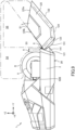
- FIGS. 12 and 21 show a profile PF2 in a side view and a top view of the printer cover 3, respectively, at the open position corresponding to an open angle ⁇ less than the maximum open angle.
- space of a distance SP exists between the roll body R set in the printer 1 and the side surface portions 125 of the printer cover 3.
- space of a distance SP exists between the roll body R set in the printer 1 and the rear surface portion 123 of the printer cover 3.
- FIG. 9 is a side view of the printer 1 with the printer cover 3 open by the maximum open angle.
- part of the roll body R refers to the portion of the roll body R set in the printer 1 that overlaps with the printer cover 3 as seen in a side view when the printer cover 3 is at the closed position.
- the exposed part of the roll body R is the portion higher than the height of the lower end of the core 7 of the roll body R set in the printer 1 by the roll body guides 6.
- the roll body guides 6 overlap with the printer cover 3.
- the printer cover 3 is open at the maximum open angle, the roll body guides 6 are exposed. Accordingly, by opening the printer cover 3 by the maximum open angle, the user can readily remove the roll body R from the roll body guides 6 or set a new roll body R on the roll body guides 6.
- This open angle is the maximum open angle where the printer cover 3 is in the fully open position.
- open space S3 is formed above the entire roll body R.
- the open space S3 extends to the region surrounded by the upper surface portion 122, the inclined surface portion 124, the rear surface portion 123, and the pair of side surface portions 125 of the printer cover 3 that is open rearward over the hinge 8.
- the open space S3 shown in FIG. 9 is greater by a portion S5 that occurs by the difference in the open angle of the printer cover 3.
- the user can set the roll body R in the roll body accommodating chamber 9 from above within a considerably wider range. That is, the roll body R can be set in the roll body accommodating chamber 9 not just from directly above but also from above in a relatively angled manner.
- the user can remove the roll body R accommodated in the roll body accommodating chamber 9 upward within a considerably wider range. That is, the roll body R accommodated in the roll body accommodating chamber 9 can be removed not just toward directly above but also toward above in a relatively angled manner.
- the user can easily correct the orientation of the roll body R by: grasping radially externally the sides of the roll body R; removing the roll body R from the pair of roll body guides 6; reversing the orientation of the roll body R; and setting the roll body R on the pair of roll body guides 6.
- the end surfaces 152 of the cover-side buffer members 151 abuts on the upper surfaces 143 of the body-side buffer members 141, thereby causing the open angle of the printer cover 3 to be the maximum open angle.
- part of the cover-side buffer members 151 is disposed frontward than the rear ends of the body-side buffer members 141, and the upper surfaces 143 of the body-side buffer members 141 and the end surfaces 152 of the cover-side buffer members 151 abut on each other. Accordingly, the maximum open angle becomes greater as compared to the case where part of the cover-side buffer members 151 is not disposed frontward than the rear ends of the body-side buffer members 141.
- the upper surfaces 143 of the body-side buffer members 141 which abut on the cover-side buffer members 151 when the printer cover 3 is open, are not the end surfaces 142 of the body-side buffer members 141 on the plane P in FIG. 6 .
- the end surfaces 152 of the cover-side buffer members 151 which abut on the body-side buffer members 141 when the printer cover 3 is open, are on the plane P in FIG. 6 as described above (see FIG. 6 ).
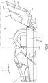
- FIGS. 12 and 22 show the profile PF3 in a side view and a top view of the printer cover 3, respectively, at the open position corresponding to the maximum open angle ⁇ max.
- space of a distance SP exists between the roll body R set in the printer 1 and the side surface portions 125 of the printer cover 3.
- space of a distance SP exists between the roll body R set in the printer 1 and the rear surface portion 123 of the printer cover 3.
- the front inner surface portion 161 is oriented upward so that the platen roller 10 is set on or detached from the attachment part 163 from above. Accordingly, by opening the printer cover 3 by the maximum open angle, the platen roller 10 can easily be set on or detached from the attachment part 163 from above.
- a distance D falls within a range of zero to a predetermined distance.
- the distance D is a distance from a ridge part E2, which corresponds to the lower end of the printer cover 3 when the printer cover 3 is open at the maximum open angle, to the placement plane on which the printer 1 is placed.
- the ridge part E2 is the portion where the rear surface portion 123 and the inclined surface portion 124 are joined to each other.
- the predetermined distance is very short, e.g., several percentages, relative to the distance from the placement plane on which the printer 1 is placed to the horizontal boundary line 133 of the printer cover 3 (see FIGS. 3 and 4 ). That is, the maximum open angle can be set so that the printer cover 3 is opened until the distance from the placement plane on which the printer 1 is placed to the portion corresponding to the lower end of the printer cover 3 (i.e., the ridge part E2) becomes very short.
- the following discussion relates to the effects on the open angle of the printer cover by the shape and dimension of the printer cover, the body case, and the buffer members, and the hinge position.
- FIGS. 13A to 13F show how the maximum open angle varies depending on the height of the body case and the height of the printer cover.
- FIG. 13A is a side view of a comparative example 1 with its printer cover closed.
- FIG. 13B is a side view of the comparative example 1 with its printer cover open by the maximum open angle.
- FIG. 13C is a side view of a comparative example 2 with its printer cover closed.
- FIG. 13D is a side view of the comparative example 2 with its printer cover open by the maximum open angle.
- FIG. 13E is a side view of a comparative example 3 with its printer cover closed.
- FIG. 13F is a side view of the comparative example 3 with its printer cover open by the maximum open angle.
- the comparative example 1 shown in FIGS. 13A and 13B shows that, when the height of a body case 201 and the height of a printer cover 202 is identical to each other, the printer cover 202 can be opened at 180 degrees about a hinge 203.
- the comparative example 2 shown in FIGS. 13C and 13D shows that, when the height of a body case 211 is higher than the height of a printer cover 212, the printer cover 212 can be opened at 180 degrees about a hinge 213.
- the comparative example 3 shown in FIGS. 13E and 13F shows that, when the height of a body case 221 is lower than the height of a printer cover 222, the printer cover 222 will abut on the placement surface 20 of the printer before the printer cover 222 is opened at 180 degrees about a hinge 223.
- FIGS. 14A to 14F show how maximum open angle varies depending on the mounting position of the hinge in the front-rear direction.
- FIG. 14A is a side view of the comparative example 1 with its printer cover closed.
- FIG. 14B is a side view of the comparative example 1 with its printer cover open at the maximum open angle.
- FIG. 14C is a side view of a comparative example 4 with its printer cover closed.
- FIG. 14D is a side view of the comparative example 4 with its printer cover open at the maximum open angle.
- FIG. 14E is a side view of a comparative example 5 with its printer cover closed.
- FIG. 14F is a side view of the comparative example 5 with its printer cover open at the maximum open angle.
- the comparative example 1 shown in FIGS. 14A and 14B shows that, when the hinge 203 is at the rearmost end of the upper side of the body case 201 and the rearmost end of the lower side of the printer cover 202, the printer cover 202 can be opened at 180 degrees about the hinge 203.
- FIGS. 14A and 14B are identical to FIGS. 13A and 13B , respectively.
- the comparative example 4 shown in FIGS. 14C and 14D shows that, when a hinge 233 is positioned frontward than the rearmost end of the upper side of a body case 231 and the rearmost end of the lower side of a printer cover 232, the printer cover 233 can be rotated only by 90 degrees about the hinge 223.
- the comparative example 5 shown in FIGS. 14E and 14F shows that, when a hinge 243 is positioned frontward than the rearmost end of the upper side of a body case 241 and the rearmost end of the lower side of the printer cover 242, the printer cover 242 can be opened by only 90 degrees about the hinge 243.
- the height of the printer cover must be identical to or higher than that of the body case, and the hinge must be disposed rearmost in the upper side of the body case and in the lower side of the printer cover.
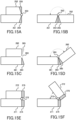
- FIGS. 15A to 15F show how the maximum open angle varies depending on the shape of the body-side buffer members and the cover-side buffer members.
- FIG. 15A is a side view of a comparative example 6 with its printer cover closed.
- FIG. 15B is a side view of the comparative example 6 with its printer cover open at the maximum open angle.
- FIG. 15C is a side view of a comparative example 7 with its printer cover closed.
- FIG. 15D is a side view of the comparative example 7 with its printer cover open at the maximum open angle.
- FIG. 15E is a side view of a comparative example 8 with its printer cover closed.
- FIG. 15F is a side view of the comparative example 8 with its printer cover open at the maximum open angle.
- body-side buffer members 254 are provided at the rear surface portion of a body case 251 and cover-side buffer members 255 are provided at the rear surface portion of a printer cover 252.
- the buffer members at the rear surface portions will not prevent the printer cover 252 from rotating at 180 degrees about a hinge 253.
- the structure of the comparative example 6 basically corresponds to the structure of the printer 1 shown in FIG. 3 . That is, in the printer 1, the rear surface portion 121 of the body case 2 is inclined to be oriented obliquely downward on the rear side, and the rear surface portion 123 of the printer cover 3 is inclined to be oriented obliquely upward on the rear side. Thus, the rear projecting part is formed at the boundary between the upper peripheral part 127 of the rear surface portion 121 of the body case 2 and the lower peripheral part 129 of the rear surface portion 123 of the printer cover 3. Thus, the body-side buffer members 141 at the rear surface portion 121 of the body case 2 and the cover-side buffer members 151 at the rear surface portion 123 of the printer cover 3 will not prevent the printer cover 3 from being opened nearly at the 180 degrees about the hinge 8.
- the body-side buffer members 254 and the cover-side buffer members 255 are not reduced in thickness enough in some regions (e.g., around the hinge 253).
- the rear surface portion of a body case 261 and the rear surface portion of a printer cover 262 are perpendicular to the placement surface of the body case 261. Furthermore, body-side buffer members 264 whose side sectional shape is triangular are provided at the rear surface portion of the body case 261, and cover-side buffer members 265 whose side sectional shape is triangular are provided at the rear surface portion of the printer cover 262. In this case, the printer cover 262 can be opened at an angle slightly less than 180 degrees about a hinge 263.
- the rear surface portion of a body case 271 and the rear surface portion of a printer cover 272 are perpendicular to the placement surface of the body case 271.
- body-side buffer members 274 whose side sectional shape is quadrangle are provided.
- cover-side buffer members 275 whose sectional shape is quadrangle are provided.
- this shortcoming may be overcome with body-side buffer members 284 at the rear surface portion of the body case 281 and cover-side buffer members 285 at the rear surface portion of a printer cover 282.
- the body-side buffer members 284 and the cover-side buffer members 285 in the structure shown in FIG. 16A are thicker than the body-side buffer members 254 and the cover-side buffer members 255 in FIG. 15A , by identical thickness entirely.
- the printer cover 282 in the structure in FIG. 16A cannot be opened at all.
- FIG. 16A is replaced by a structure shown in FIG. 16B .
- the cover-side buffer members 285 are replaced with cover-side buffer members 285B.
- the cover-side buffer members 285B correspond to the cover-side buffer members 285 without the portion around the hinge 283.
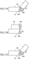
- the printer cover 282 can be opened at about 60 degrees. However, when the user tries to open the printer cover 282 by, for example, about 135 degrees as shown in FIG. 17A , the cover-side buffer members 285B interfere with the body-side buffer members 284B.
- the structure shown in FIG. 16B is replaced with a structure shown in FIG. 17B .
- the body-side buffer members 284 are replaced with body-side buffer members 284B.
- a portion around the hinge 283 does not exist in the body-side buffer members 284B. This increases an open angle of the printer cover 282.
- the printer cover 282 can be opened at about 135 degrees.
- the rear surface portion of the body case 281 is inclined to be oriented obliquely downward on the rear side
- the rear surface portion of the printer cover 282 is inclined to be oriented obliquely upward on the rear side.
- the body-side buffer members 284B are disposed at the rear surface portion of the body case 281 except for the portion around the hinge 283.
- the cover-side buffer members 285B are disposed at the rear surface portion of the printer cover 282 except for the portion around the hinge 283. In this case, the printer cover 282 can be opened up to about 135 degrees about the hinge 283.
- the structure shown in FIGS. 17B and 17C corresponds to the structure of the printer 1. That is, in the printer 1, the body-side buffer members 141 provided at the rear surface portion 121 of the body case 2 and the cover-side buffer members 151 provided at the rear surface portion 123 of the printer cover 3 are shaped as illustrated in FIG. 5 . This allows the body-side buffer members 141 and the cover-side buffer members 151 to have thickness to some extent in the front-rear direction. While having the buffer members with some thickness, the structure of the printer 1 allows for the great maximum open angle of the printer cover 3 about the hinge 8 at which the body-side buffer members 141 and the cover-side buffer members 151 abut on each other.
- each body-side buffer member 141 has the upper surface 143.
- a portion of the cover-side buffer member 151 is removed such that each cover-side buffer member 151 has the lower surface 154. This increases the maximum open angle of the printer cover 3 at which the body-side buffer members 141 and the cover-side buffer members 151 abut on each other. Furthermore, the maximum open angle can be adjusted by setting the removed portions as appropriate.
- FIG. 23 shows the profile PF1 of the printer cover 3 at the closed position, the profile PF3 of the printer cover 3 open by the maximum open angle, and center C of the hinge shaft 81.
- the printer cover 3 can be opened or closed between the closed position and the open position at the maximum open angle.
- the printer cover 3 can be opened or closed between the closed position and the open position at the maximum open angle.
- the printer cover 3 cannot be rotated without any structural change for preventing the printer cover from interfering with the body case.
- a hinge 10B may be provided at a ridge line part that is formed at the joining position between the upper peripheral part of a rear surface portion 121B of a body case 2B and the lower peripheral part of a rear surface portion 123B of a printer cover 3B.
- a hinge 10C may be provided at a lower position than a ridge line part RD1 that is formed at the joining position between the upper peripheral part of a rear surface portion 121C of a body case 2C and the lower peripheral part of a rear surface portion 123C of a printer cover 3C.
- a hinge 10D may be provided at a position higher than a ridge line part RD2 that is formed at the joining position between the upper peripheral part of a rear surface portion 121D of a body case 2D and the lower peripheral part of a rear surface portion 123D of a printer cover 3D.
- the printer cover 3 may be displaced rearward so that the lower peripheral part 129 of the rear surface portion 123 of the printer cover 3 is disposed on the rear side than the upper peripheral part 127 of the rear surface portion 121 of the body case 2.
- the maximum open angle can be increased as in the case shown in FIG. 12 .
- the printer cover 3 may be displaced frontward so that the lower peripheral part 129 of the rear surface portion 123 of the printer cover 3 is disposed on the front side than the upper peripheral part 127 of the rear surface portion 121 of the body case 2.
- the maximum open angle can be increased as in the case shown in FIG. 12 .
- FIG. 29 is a side view of the printer 1 according to an embodiment, showing the profile PF1 of the printer cover 3 at the closed position and the profile PF3 of the printer cover 3 open by the maximum open angle.
- the printer cover 3 of the printer 1 includes the upper surface portion 122, the inclined surface portion 124, and the rear surface portion 123.
- the inclined surface portion 124 is provided between the hinge shaft 81 and the upper surface portion 122, and is inclined relative to the placement surface 20.
- H1 ⁇ H2 is established where H1 is the height from the placement surface 20 to the hinge shaft 81 and H2 is the height from the placement surface 20 to a highest position 122e from the hinge shaft 81 to the upper surface portion 122. That is, in the printer 1, the hinge shaft 81 is set relatively low in the height direction of the printer 1. By setting the hinge shaft 81 low in this manner, the inside of the printer is widely opened when the printer cover 3 is set at the open position.
- the inclined surface portion 124 is formed at the printer cover 3, the inclined surface portion 124 can be brought closer to the placement surface 20. As compared to the case where the inclined surface portion 124 is not provided, the maximum open angle of the printer cover becomes greater.
- FIG. 30A is a side view of a printer according to a comparative example at the closed position and at the open position.
- FIGS. 30B to 30D are side views of the printer according to the embodiment at the closed position and at the open position.
- H1 ⁇ H2 is satisfied where H1 is defined as the height from the placement surface 20A to the hinge shaft 81A and H2 is defined as the height from the hinge shaft 81A to the upper surface portion.
- FIG. 30A shows a printer in which a body case 2A and a printer cover 3A are coupled to each other by a hinge shaft 81A.
- the inclined surface portion is not formed at the printer cover 3A, and the upper surface portion 122A and the rear surface portion 123A are continuous.
- the corner at the rear end of the printer cover 3A abuts on the placement surface 20A, which prevents a maximum open angle ⁇ a from increasing.
- FIG. 30B shows a printer in which the body case 2A and a printer cover 3B are coupled to each other by the hinge shaft 81A.
- an inclined surface portion 124B is formed at the printer cover 3B similarly to the printer 1 shown in FIG. 29 .
- a maximum open angle ⁇ b of the printer cover 3B can become relatively great by virtue of the inclined surface portion 124B ( ⁇ b > ⁇ a).
- FIG. 30C shows a printer in which the body case 2A and a printer cover 3C are coupled to each other by the hinge shaft 81A.
- the printer shown in FIG. 30C is different from that in FIG. 30B in that an inclined surface portion 124C of the printer cover 3C extends from the hinge shaft 81A, or from around the hinge shaft 81A, toward an upper surface portion 122C.
- a maximum open angle ⁇ c of the printer cover 3C can become relatively great by virtue of the inclined surface portion 124C ( ⁇ c > ⁇ a).
- FIG. 30D shows a printer in which the body case 2A and a printer cover 3D are coupled to each other by the hinge shaft 81A.
- the printer shown in FIG. 30D is different from those in FIGS. 30B and 30C in that an inclined surface portion 124D of the printer cover 3D is a curved surface.
- a maximum open angle ⁇ d of the printer cover 3D can become relatively great by virtue of the inclined surface portion 124D ( ⁇ d > ⁇ a).
- the maximum open angle of the printer cover increases by virtue of the inclined surface portion inclined relative to the placement surface between the hinge shaft and the upper surface portion in the printer.
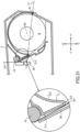
- FIG. 31 is a partial cross-sectional view of the printer 1 with the printer cover 3 at the closed position.
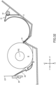
- FIG. 32 is a partial cross-sectional view of the printer 1 with the printer cover 3 at the open position.
- the hinge shaft 81 is at a lower position than center RC of the roll body R (identical to the center of the roll body guides 6). Accordingly, most of the outer circumferential surface of the roll body R is exposed, thereby making it easier for the user to access the roll body R near the hinge shaft 81. Thus, advantageously, the roll body R is easily replaced.
- the printer cover 3 includes a tapered part 31.
- the tapered part 31 is tapered by a feeding surface 311 and a curved surface 312.
- the feeding surface 311 faces the continuous sheet CP drawn out from the roll body R and forms a feeding path PP. That is, as shown in FIG. 31 in an enlarged manner, when the printer cover 3 is at the closed position, the feeding surface 311 of the tapered part 31 and an inclined surface 29 inside the printer are opposed to each other with a slight clearance, thereby forming the feeding path PP for the continuous sheet CP.
- the curved surface 312 is a surface along the outer circumferential surface of the roll body R.
- the printer cover 3 When the printer cover 3 at the closed position, the curved surface 312 supports the roll body R accommodated in the roll body accommodating chamber 9.
- the tapered part 31 is disposed so that a virtual line L1 connecting between a tip 313 of the tapered part 31 and the hinge shaft 81 passes a lower position than the center RC of the roll body R (i.e., the center of the roll body guides 6). Accordingly, when the printer cover 3 is set at the open position for replacing the roll body R, as shown in FIG. 32 , the space where the user's hand can easily access is formed in front of the roll body R (that is, the space that has been occupied by the tapered part 31 when the printer cover 3 is at the closed position). That is, when the user removes the roll body R from the roll body accommodating chamber 9, the structure makes it easy for the user to grasp the roll body R by inserting his/her hand into the space in front of and behind the roll body R.
- the present invention relates to Japanese Patent Applications Nos. JP 2020-191645 and JP 2021-156365 filed with the Japan Patent Office on November 18, 2020 and September 27, 2021, respectively, all of which are incorporated herein by reference.
- the present invention relates to a printer comprising: a body case that includes a placement surface for the printer and an accommodating chamber for accommodating a roll body into which a belt-shaped print medium are wound; a printer cover configured to open and close the accommodating chamber; a platen roller that is attached to the printer cover and configured to convey the belt-shaped print medium drawn out of the roll body; and a hinge that includes a hinge shaft and is configured to couple the printer cover with the body case so that the printer cover is swingable about the hinge shaft relative to the body case, wherein the printer cover comprises an upper surface portion and an inclined surface portion, the inclined surface portion being provided between the hinge shaft and the upper surface portion and inclined relative to the placement surface, and H1 ⁇ H2 is established where H1 is defined as a height from the placement surface to the hinge shaft and H2 is defined as a height from the placement surface to a highest position from the hinge shaft to the upper surface portion.
- the printer further comprising roll body guides configured to support both side surfaces of the roll body accommodated in the accommodating chamber, wherein the hinge shaft is disposed at a lower position than a center of the roll body guides.
- the printer cover includes: a tapered part that is tapered by a curved surface that supports the roll body accommodated in the accommodating chamber when the printer cover is at a closed position, and a feeding surface that faces the belt-shaped print medium drawn out of the roll body to form a feeding path, and the tapered part is disposed so that a virtual line passes a lower position than the center of the roll body guides as seen in a side view, the virtual line being connecting between a tip of the tapered part and the hinge shaft.
- the printer cover has a two-layer structure comprised of an inner printer cover and an outer printer cover.
- the body case includes a body-side buffer member
- the printer cover includes a cover-side buffer member
- the body-side buffer member and the cover-side buffer member are disposed via the hinge interposed therebetween and abut on each other when the printer cover is at an open position.
- the body-side buffer member and the cover-side buffer member respectively have end surfaces that are positioned on an identical plane perpendicular to the placement surface when the printer cover is at the closed position.
- the printer cover includes an attachment part where the platen roller is detachably attached, and the attachment part is oriented upward to allow the platen roller to be attached and detached when the printer cover is at the open position.
Landscapes
- Accessory Devices And Overall Control Thereof (AREA)
- Unwinding Webs (AREA)
- Handling Of Continuous Sheets Of Paper (AREA)
Abstract
Description
- The present invention relates to a printer that prints information on a print medium.
- Conventionally, thermal printers that print on a print medium by thermal transfer are known (hereinafter simply referred to as "printers"). In such printers, a print medium is held in a pressurized state between a thermal head and a platen roller, and heating elements on the thermal head are selectively heated to print.
- In some printers, the platen roller is attached to an openable printer cover provided at the upper part of a roll body accommodating chamber (e.g.,
Japanese Laid-open Patent publication No. 2014-188708 Japanese unexamined Utility Model Application Publication No. H6-52274 - In the printer disclosed in the Publication No.
2014-188708 , the printer cover is opened about a hinge located substantially at the upper end of the rear of the body, but it does not fully open the roll body accommodating chamber. The user cannot easily set in or remove a roll body from the roll body accommodating chamber. - In the printer disclosed in the Publication No.
H6-52274 - Therefore, even when the printer cover is fully open, it still covers at least the upper half of the roll body accommodating chamber, preventing the user from easily setting or removing the roll body from the roll body accommodating chamber.
- An object of the present invention is to provide a printer with a great maximum open angle by which a printer cover is opened.
- An embodiment of the present invention is a printer including: a body case that includes a placement surface for the printer and an accommodating chamber for accommodating a roll body into which a belt-shaped print medium are wound; a printer cover configured to open and close the accommodating chamber; a platen roller that is attached to the printer cover and configured to convey the belt-shaped print medium drawn out of the roll body; and a hinge that includes a hinge shaft and is configured to couple the printer cover with the body case so that the printer cover is swingable about the hinge shaft relative to the body case. The printer cover comprises an upper surface portion and an inclined surface portion, the inclined surface portion being provided between the hinge shaft and the upper surface portion and inclined relative to the placement surface. H1 < H2 is established where H1 is defined as a height from the placement surface to the hinge shaft and H2 is defined as a height from the placement surface to a highest position from the hinge shaft to the upper surface portion.
- An embodiment of the present invention increases the maximum open angle by which the printer cover is opened.
-
-
FIG. 1A is a perspective view of a printer according to an embodiment, showing its front, top, and left faces with its printer cover closed. -
FIG. 1B is a perspective view of the printer according to an embodiment, showing its front, top, and left faces with its printer cover open by a maximum open angle. -
FIG. 2 is a rear perspective view of the printer according to an embodiment, showing its rear, top, and left faces with its printer cover open by a maximum open angle. -
FIG. 3 is a side view of the printer according to an embodiment, with its printer cover closed. -
FIG. 4 is a rear view of the printer according to an embodiment, with its printer cover closed. -
FIG. 5 is an enlarged partial perspective view showing the rear surface of the printer according to an embodiment, with its printer cover closed. -
FIG. 6 is an enlarged partial side view of the printer according to an embodiment, with its printer cover closed. -
FIG. 7 is a second rear view of the printer according to an embodiment, with its printer cover closed. -
FIG. 8 is a side view of the printer according to an embodiment, with its printer cover open by an open angle less than the maximum open angle. -
FIG. 9 is a side view of the printer according to an embodiment, with its printer cover open by the maximum open angle. -
FIG. 10 is a perspective view of the printer according to an embodiment, showing its rear, bottom, and left faces with its printer cover open by the maximum open angle. -
FIG. 11 is an enlarged partial side view of the printer according to an embodiment, with its printer cover open by the maximum open angle. -
FIG. 12 shows the printer according to an embodiment, with its printer cover closed, open by an open angle less than the maximum open angle, and open by the maximum open angle. -
FIGS. 13A to 13F are schematic explanatory illustrations about the open angle of the printer cover. -
FIGS. 14A to 14F are schematic explanatory illustrations about the open angle of the printer cover. -
FIGS. 15A to 15F are schematic explanatory illustrations about the open angle of the printer cover. -
FIGS. 16A to 16C are schematic explanatory illustrations about the open angle of the printer cover. -
FIGS. 17A to 17C are schematic explanatory illustrations about the open angle of the printer cover. -
FIG. 18 is a side sectional view of the printer according to an embodiment,. -
FIG. 19 is a perspective view of the printer according to an embodiment, showing a roll body accommodating chamber and the inner surface of the printer cover with its printer cover open. -
FIG. 20 is a perspective view of the printer according to an embodiment, showing the inner surface of an outer printer cover with its printer cover open. -
FIG. 21 is a top view of the printer according to an embodiment, showing the roll body accommodating chamber and the inner surface of the printer cover with its printer cover open by an open angle less than the maximum open angle. -
FIG. 22 is a top view of the printer according to an embodiment, showing the roll body accommodating chamber and the inner surface of the printer cover with its printer cover open by the maximum open angle. -
FIG. 23 is a partial side view of the printer according to an embodiment, with its printer cover open by the maximum open angle. -
FIG. 24 is a side view of the printer according to an embodiment, and other printers showing the position of their hinges. -
FIGS. 25A and 25B show a printer according a variation. -
FIGS. 26A and 26B show a printer according a variation. -
FIGS. 27A and 27B show a printer according a variation. -
FIGS. 28A and 28B show a printer according a variation. -
FIG. 29 is an explanatory illustration about the positional relationship between the body case, the printer cover, and the hinge of the printer according to an embodiment,. -
FIGS. 30A to 30D are side views of printers according to various modes in their closed position and open position. -
FIG. 31 is a partial cross-sectional view of the printer according to an embodiment, with its printer cover at the closed position. -
FIG. 32 is a partial cross-sectional view of the printer according to an embodiment, with its printer cover at the open position. - In the following, a description will be given of embodiments, of a printer of the present invention.
- In the following, with reference to
FIGS. 1A, 1B , and2 , a description will be given of aprinter 1 according to an embodiment. -
FIG. 1A is a perspective view of theprinter 1 according to the embodiment showing its front, top, and left faces with theprinter cover 3 closed.FIG. 1B is a perspective view of theprinter 1 according to the embodiment showing its front, top, and left faces with theprinter cover 3 open.FIG. 2 is a perspective view of theprinter 1 according to the embodiment of the present invention showing its rear, upper, and left faces. - As shown in
FIGS. 1A, 1B , and2 , theprinter 1 according to the present embodiment includes abody case 2, aprinter cover 3, adisplay panel 4, aplaten roller 10, and athermal head 28. - As shown in
FIG. 1A , the bottom surface of theprinter 1 is substantially rectangular. A direction along its long side is defined as a front-rear direction. That is, it is defined that a side with thedisplay panel 4 is the front (-Y) and the opposite printer cover side is the rear (+Y). The right side (-X), the left side (+X), the top side (+Z), and the bottom side (-Z) are defined relative to the front-rear direction. In the following description, as appropriate, the right (-X) or left (+X) direction is referred to as the lateral direction, and the top (+Z) or bottom (-Z) direction is referred to as the top-bottom direction. In the drawings, the directions may be defined on XYZ axes. - As shown in
FIG. 2 , theprinter 1 may include a rollbody accommodating chamber 9 for accommodating a roll body, which has a sheet of paper wound around to be printed. Thebody case 2 may include aninner bottom surface 2a (seeFIG. 18 ) for the roll body to be placed on. - The
printer cover 3 is a cover that opens or shuts off the inside (e.g., the roll body accommodating chamber 9) of theprinter 1. Ahinge 8, including ahinge shaft 81, is provided at the rear end of theprinter cover 3. Thehinge 8 rotatably supports theprinter cover 3 to be rearwardly openable relative to the body case. As used herein, "rearwardly openable" means that theprinter cover 3 is opened about thehinge 8 on the rear end side of theprinter cover 3. - The
display panel 4 functions as an input/output interface for the user, and is a liquid crystal display panel with the touchscreen function, for example. - As shown in
FIG. 2 , anattachment part 163 is provided at a frontinner surface portion 161 of theprinter cover 3, which is an inner surface portion opposite to the side where thehinge 8 is. Theattachment part 163 holds aplaten roller 10 to be rotatable in the forward and reverse directions. As shown inFIG. 18 , when theprinter cover 3 is closed, theplaten roller 10 is disposed behind thethermal head 28. - The
platen roller 10 is conveying means that is mounted on theprinter cover 3 and conveys a continuous sheet CP drawn out of a roll body R, which is accommodated in the rollbody accommodating chamber 9 while retained by a pair of roll body guides 6. The platen roller extends along the width direction of the roll body R. Theplaten roller 10 is mechanically coupled to a stepping motor (not shown) or the like to be driven. - The roll body R includes a
core 7 and the belt-shaped continuous sheet CP wound around thecore 7. - The roll body guides 6 support both side surfaces of the roll body R accommodated in the roll
body accommodating chamber 9. The center of the roll body guides 6 matches the center of the roll body R. - As shown in
FIG. 18 , thehinge 8 is disposed at a lower position than anaxis 6a of the roll body guides 6. Accordingly, thehinge 8 is positioned lower than the axis of the roll body R set in theprinter 1 by the roll body guides 6. Thus, thehinge 8 is positioned frontward in the front-rear direction as compared to the case where thehinge 8 is disposed at the identical height to theaxis 6a of the roll body guides 6. This reduces the size of theprinter 1 in the front-rear direction. - The
thermal head 28 is printing means that prints information such as characters, symbols, graphics, or barcodes on the sheet of the roll body R. As shown inFIG. 18 , when theprinter cover 3 is closed, the printing surface of thethermal head 28 faces a feeding path of the sheet and is opposed to theplaten roller 10. A plurality of heat elements (not shown) that generate heat when energized are arranged on the printing surface of thethermal head 28 along the width direction of the sheet. Thethermal head 28 is connected to a circuit board (not shown) that transmits print signals to thethermal head 28. - As shown in
FIG. 18 , on the back side of thethermal head 28, acoil spring 157 as a biasing member is provided for providing biasing force to thethermal head 28. - When the
printer cover 3 is closed and printing is carried out, the sheet is held between theplaten roller 10 and thethermal head 28 while conveyed by theplaten roller 10. Here, thethermal head 28 is pressed against theplaten roller 10 by the biasing force, generating a head pressure suitable for printing. - The
body case 2 includes the rollbody accommodating chamber 9. Around the rollbody accommodating chamber 9, thebody case 2 covers the lower half of the rollbody accommodating chamber 9 on the right and left sides and from behind. As shown inFIG. 3 , the bottom surface of thebody case 2 is aplacement surface 20 on which theprinter 1 is placed for operation. - As shown in
FIG. 3 , arear surface portion 121 of thebody case 2 is inclined to be oriented obliquely downward on the rear side. - Around the roll
body accommodating chamber 9, theprinter cover 3 covers the upper half of the roll body accommodating chamber on the right and left sides and from behind and above. - As shown in
FIG. 3 , arear surface portion 123 of theprinter cover 3 is inclined to be oriented obliquely upward on the rear side. - Accordingly, a rear projecting part is formed at the boundary between an upper
peripheral part 127 of therear surface portion 121 of thebody case 2 and a lowerperipheral part 129 of therear surface portion 123 of theprinter cover 3. Accordingly, the boundary between the upperperipheral part 127 of therear surface portion 121 of thebody case 2 and the lowerperipheral part 129 of therear surface portion 123 of theprinter cover 3 is at a position projecting on the rear side of theprinter 1. - As shown in
FIG. 3 , when theprinter cover 3 is at the closed position, a pair offront sides 125a ofside surface portions 125 on the right and left sides of theprinter cover 3 are inclined downward toward the rear. The pair offront sides 125a are positioned farthest from thehinge 8 in theside surface portions 125, which are opposed to and spaced apart from each other in the axial direction of thehinge shaft 81, of theprinter cover 3. The pair offront sides 125a are inclined toward thehinge 8 side from the open side to the closed side of theprinter cover 3. Accordingly, when theprinter cover 3 is opened or closed, theside surface portions 125 will not interfere with thebody case 2. - The
printer cover 3 can be opened and closed about the axis of thehinge 8 between the closed position shown inFIG. 3 and the open position at the maximum open angle shown inFIG. 9 . Here, the maximum open angle refers to the angle at which theprinter cover 3 cannot further be rotated by cover-side buffer members 151 that is provided at therear surface portion 123 of theprinter cover 3. At the maximum open angle, the cover-side buffer members 151 abut on body-side buffer members 141 provided at therear surface portion 121 of thebody case 2. - As shown in
FIG. 18 , as seen in a side view, theprinter cover 3 includes anupper surface portion 122, aninclined surface portion 124, and arear surface portion 123. Theinclined surface portion 124 and theupper surface portion 122 continue in this order, to the side of therear surface portion 123 opposite to thehinge 8. As seen in the extending direction of the hinge 8 (i.e., in a side view), therear surface portion 123 and theinclined surface portion 124 are connected at an obtuse interior angle (about 135 degrees). Theinclined surface portion 124 and theupper surface portion 122 are connected at an obtuse interior angle (about 135 degrees). An angle between therear surface portion 123 and theupper surface portion 122 is about 90 degrees. Theupper surface portion 122, theinclined surface portion 124, and therear surface portion 123 surround the roll body R accommodated in the rollbody accommodating chamber 9. This structure reduces the size of theprinter cover 3. As shown inFIG. 9 , theinclined surface portion 124 becomes substantially horizontal when theprinter cover 3 is opened by the maximum open angle. Provided that theinclined surface portion 124 does not exist and theupper surface portion 122 and therear surface portion 123 are coupled directly to each other, an angle by which the boundary side between theupper surface portion 122 and therear surface portion 123 abuts on the printer placement surface becomes the maximum open angle. In this case, the maximum open angle will be less than the maximum open angle of theopen printer cover 3 shown inFIG. 9 . Thus, theinclined surface portion 124 allows for increase of the maximum open angle. - As shown in
FIG. 19 , in an embodiment, theprinter cover 3 has a two-layer structure comprised of aninner printer cover 36 and anouter printer cover 37 in view of toughness. Theprinter cover 3 is not specified to have such a double structure, and may be comprised of a single member. - The
hinge 8 couples theprinter cover 3 to thebody case 2 to be capable of being opened and closed. That is, thehinge 8 couples theprinter cover 3 with thebody case 2 so that theprinter cover 3 can swing about the hinge shaft 81 (described later) relative to thebody case 2. - As shown in
FIGS. 3 and4 , thehinge 8 rotatably couples the upperperipheral part 127 of therear surface portion 121 of thebody case 2 with the lowerperipheral part 129 of therear surface portion 123 of theprinter cover 3. Thehinge 8 extends in the lateral direction of thebody case 2. Accordingly, thehinge 8 extends around the boundary between the upperperipheral part 127 of therear surface portion 121 of thebody case 2 and the lowerperipheral part 129 of therear surface portion 123 of theprinter cover 3. - As shown in
FIGS. 4 and19 , thehinge 8 includes thehinge shaft 81, body-side shaft-supportinglong holes 82, inner printer cover-side shaft-supporting round holes 83, outer printer cover-side shaft-supporting round holes 84, and atorsion spring 85. - The pair of body-side shaft-supporting
long holes 82 are provided at the right and left ends near the rear end of the rollbody accommodating chamber 9. The body-side shaft-supportinglong holes 82 have a long axis in the front-rear direction (i.e., Y-axis direction). Here, the long axis direction of the body-side shaft-supportinglong holes 82 may be slightly displaced from the front-rear direction. - The pair of inner printer cover-side shaft-supporting round holes 83 are provided at the rear end of the
inner printer cover 36. - The pair of the outer printer cover-side shaft-supporting round holes 84 are provided at the rear end of the
outer printer cover 37. - The
hinge shaft 81 is inserted through the pair of inner printer cover-side shaft-supporting round holes 83 and the pair of outer printer cover-side shaft-supporting round holes 84. Thehinge shaft 81 has its both ends inserted into the pair of body-side shaft-supportinglong holes 82. - The
hinge shaft 81 extends in the lateral direction at the upperperipheral part 127 of therear surface portion 121 of thebody case 2. Accordingly, the body-side shaft-supportinglong holes 82, the inner printer cover-side shaft-supporting round holes 83, and the outer printer cover-side shaft-supporting round holes 84 are also provided at the upperperipheral part 127 of therear surface portion 121 of thebody case 2. The inner printer cover-side shaft-supporting round holes 83 and the outer printer cover-side shaft-supporting round holes 84 of theprinter cover 3 are positioned lower than a horizontal boundary line 133 (seeFIGS. 3 and4 ) between thebody case 2 and theprinter cover 3. - While not shown in the drawings, the
inner printer cover 36 and theouter printer cover 37 are integrated by being screwed to each other. When theinner printer cover 36 and theouter printer cover 37 are screwed, theinner printer cover 36 and theouter printer cover 37 can rotate about thehinge shaft 81 while being integrated. On the other hand, when theinner printer cover 36 and theouter printer cover 37 are not screwed, they can separately rotate about thehinge shaft 81.FIG. 19 shows theinner printer cover 36 and theouter printer cover 37 integrated by being screwed to each other.FIG. 20 shows theinner printer cover 36 and theouter printer cover 37 not being screwed but separated from each other. - Accordingly, when the
hinge shaft 81 slides in the front-rear direction, the integratedinner printer cover 36 andouter printer cover 37 slide together in the front-rear direction. That is, when thehinge shaft 81 slides in the front-rear direction, theprinter cover 3 slides in the front-rear direction. - The integrated
inner printer cover 36 andouter printer cover 37 can rotate together about thehinge shaft 81. That is, theprinter cover 3 can rotate about thehinge shaft 81. - The
torsion spring 85 biases theprinter cover 3 to open theclosed printer cover 3. - The body-side shaft-supporting
long holes 82 whose long axes are elongated in the front-rear direction allows the shaft of thehinge 8 to slide in the front-rear direction. - Note that, when the
printer cover 3 has an integral structure instead of the double structure comprised of theinner printer cover 36 and theouter printer cover 37, not both the inner printer cover-side shaft-supporting round holes 83 and the outer printer cover-side shaft-supporting round holes 84 are required and one of them will suffice. - As shown in
FIG. 4 , in an embodiment, a plurality of body-side buffer members 141 are arranged in the lateral direction on therear surface portion 121 of thebody case 2. In the embodiment inFIG. 4 , three body-side buffer members 141 are arranged in the lateral direction on each of the right and left sides of therear surface portion 121 of thebody case 2. - Similarly, in an embodiment, a plurality of cover-
side buffer members 151 are arranged in the lateral direction on therear surface portion 123 of theprinter cover 3. In the embodiment inFIG. 4 , three cover-side buffer members 151 are arranged in the lateral direction on each of the right and left sides of therear surface portion 123 of theprinter cover 3. The present invention is not limited thereto and a single body-side buffer members and a single cover-side buffer members may be provided. - In an embodiment, as shown in
FIG. 4 , the body-side buffer members 141 and the cover-side buffer members 151 are opposed to each other with reference to thehinge 8. - In the embodiment in
FIG. 4 , the body-side buffer members 141 and the cover-side buffer members 151 form pairs at the identical positions in the lateral direction. -
FIG. 5 is an enlarged partial view corresponding toFIG. 4 . As shown inFIG. 5 , in an embodiment, the body-side buffer members 141 each include a total of five surfaces, i.e., atip surface 142, anupper surface 143, alower surface 144, aleft surface 145, and aright surface 146. Similarly, the cover-side buffer members 151 each include a total of five surfaces, i.e., atip surface 152, anupper surface 153, alower surface 154, aleft surface 155, and aright surface 156. - As shown in
FIG. 12 , in the open angle range from the angle of theprinter cover 3 at the closed position (where theprinter cover 3 has a profile PF 1) to the maximum open angle (where theprinter cover 3 has a profile PF3), theprinter cover 3 does not interfere with thebody case 2. - The profile PF1 shown in
FIG. 12 is a profile of theprinter cover 3 at the closed position (where the open angle is zero degrees). - When the
printer cover 3 is at the closed position, as seen in a side view, the roll body R is covered with thebody case 2 and theprinter cover 3 so that the roll body R set in theprinter 1 partially overlaps with theprinter cover 3. - As shown in
FIG. 1B , it is apparent that theprinter cover 3 partially covers part of the roll body R set in theprinter 1 as seen from the rear projection plane irrespective of the open angle of theprinter cover 3. - Accordingly, as shown in
FIGS. 1B and12 , when theprinter cover 3 is at the closed position, theprinter cover 3 partially covers at least part of the roll body R set in theprinter 1 as seen from any of the upper projection plane, the side projection plane, and the rear projection plane. Thus, theprinter cover 3 covers, with a gap, the roll body R set in theprinter 1, from above, both sides, and behind. - In an embodiment, as shown in
FIGS. 6 and7 , when theprinter cover 3 is at the closed position, the end surfaces 152 of the cover-side buffer members 151 and the end surfaces 142 of the body-side buffer members 141 are on an identical plane P. The plane P is perpendicular to theplacement surface 20 for theprinter 1 to be placed upright. - No components or parts are disposed in the
printer 1 behind the plane P. Specifically, therear surface portion 121 of thebody case 2 is positioned on the front side of the body case than the plane P. Therear surface portion 123 of theprinter cover 3 is positioned on the front side of the body case than the plane P. Thehinge 8 is positioned on the front side of the body case than the plane P. Other portions or components of theprinter 1 are also positioned on the front side of the body case than the plane P. - Thus, the end surfaces 152 of the cover-
side buffer members 151 and the end surfaces 142 of the body-side buffer members 141 function as the bottom surfaces when theprinter 1 is placed upright. -
FIG. 8 is a side view of theprinter 1 with theprinter cover 3 open by an open angle less than the maximum open angle. - When the
printer cover 3 is open at an open angle less than the maximum open angle, the cover-side buffer members 151 do not abut on the body-side buffer members 141. - As shown in
FIG. 8 , when theprinter cover 3 is open at an open angle less than the maximum open angle, open space S1 is formed above the entire roll body R. In the front-rear direction, the open space S1 extends to the region surrounded by theupper surface portion 122, theinclined surface portion 124, therear surface portion 123, and the pair ofside surface portions 125 of theprinter cover 3 that is open rearward over thehinge 8. -
FIGS. 12 and21 show a profile PF2 in a side view and a top view of theprinter cover 3, respectively, at the open position corresponding to an open angle θ less than the maximum open angle. - As shown in
FIG. 12 , in a side view, space of a distance SP exists between the roll body R set in theprinter 1 and theside surface portions 125 of theprinter cover 3. As shown inFIG. 21 , in a top view, space of a distance SP exists between the roll body R set in theprinter 1 and therear surface portion 123 of theprinter cover 3. -
FIG. 9 is a side view of theprinter 1 with theprinter cover 3 open by the maximum open angle. - When the
printer cover 3 is open at the maximum open angle, as seen in a side view, part of the roll body R is exposed. As used herein, part of the roll body R refers to the portion of the roll body R set in theprinter 1 that overlaps with theprinter cover 3 as seen in a side view when theprinter cover 3 is at the closed position. For example, as shown inFIGS. 1A, 1B , and2 , the exposed part of the roll body R is the portion higher than the height of the lower end of thecore 7 of the roll body R set in theprinter 1 by the roll body guides 6. - When the
printer cover 3 is at the closed position, as seen in a side view, the roll body guides 6 overlap with theprinter cover 3. When theprinter cover 3 is open at the maximum open angle, the roll body guides 6 are exposed. Accordingly, by opening theprinter cover 3 by the maximum open angle, the user can readily remove the roll body R from the roll body guides 6 or set a new roll body R on the roll body guides 6. - When the
printer cover 3 at the closed position is opened to gradually increase the open angle, the cover-side buffer members 151 abut on the body-side buffer members 141 where the open angle cannot be increased further. This open angle is the maximum open angle where theprinter cover 3 is in the fully open position. - As shown in
FIG. 9 , when theprinter cover 3 is open at the maximum open angle, open space S3 is formed above the entire roll body R. In the front-rear direction, the open space S3 extends to the region surrounded by theupper surface portion 122, theinclined surface portion 124, therear surface portion 123, and the pair ofside surface portions 125 of theprinter cover 3 that is open rearward over thehinge 8. - As compared to the open space S1 shown in
FIG. 8 , the open space S3 shown inFIG. 9 is greater by a portion S5 that occurs by the difference in the open angle of theprinter cover 3. - As shown in
FIG. 9 , two ends E1 (portions where thefront sides 125a and thelower sides 125b of theside surface portions 125 are joined to each other on the right and left sides), which become the highest ends of theprinter cover 3 when theprinter cover 3 is open at the maximum open angle, are lower than the top of the roll body R. - Accordingly, the user can set the roll body R in the roll
body accommodating chamber 9 from above within a considerably wider range. That is, the roll body R can be set in the rollbody accommodating chamber 9 not just from directly above but also from above in a relatively angled manner. - Alternatively, the user can remove the roll body R accommodated in the roll
body accommodating chamber 9 upward within a considerably wider range. That is, the roll body R accommodated in the rollbody accommodating chamber 9 can be removed not just toward directly above but also toward above in a relatively angled manner. - If the roll body R has been set in the roll
body accommodating chamber 9 in the wrong orientation, the user can easily correct the orientation of the roll body R by: grasping radially externally the sides of the roll body R; removing the roll body R from the pair of roll body guides 6; reversing the orientation of the roll body R; and setting the roll body R on the pair of roll body guides 6. - Specifically with reference to
FIGS. 10 and11 , the end surfaces 152 of the cover-side buffer members 151 abuts on theupper surfaces 143 of the body-side buffer members 141, thereby causing the open angle of theprinter cover 3 to be the maximum open angle. Here, as seen in a side view, part of the cover-side buffer members 151 is disposed frontward than the rear ends of the body-side buffer members 141, and theupper surfaces 143 of the body-side buffer members 141 and the end surfaces 152 of the cover-side buffer members 151 abut on each other. Accordingly, the maximum open angle becomes greater as compared to the case where part of the cover-side buffer members 151 is not disposed frontward than the rear ends of the body-side buffer members 141. - The
upper surfaces 143 of the body-side buffer members 141, which abut on the cover-side buffer members 151 when theprinter cover 3 is open, are not the end surfaces 142 of the body-side buffer members 141 on the plane P inFIG. 6 . The end surfaces 152 of the cover-side buffer members 151, which abut on the body-side buffer members 141 when theprinter cover 3 is open, are on the plane P inFIG. 6 as described above (seeFIG. 6 ). -
FIGS. 12 and22 show the profile PF3 in a side view and a top view of theprinter cover 3, respectively, at the open position corresponding to the maximum open angle θmax. - As shown in
FIG. 12 , in a side view, space of a distance SP exists between the roll body R set in theprinter 1 and theside surface portions 125 of theprinter cover 3. As shown inFIG. 22 , as also seen from above, space of a distance SP exists between the roll body R set in theprinter 1 and therear surface portion 123 of theprinter cover 3. - As shown in
FIGS. 19 and22 , the frontinner surface portion 161 is oriented upward so that theplaten roller 10 is set on or detached from theattachment part 163 from above. Accordingly, by opening theprinter cover 3 by the maximum open angle, theplaten roller 10 can easily be set on or detached from theattachment part 163 from above. - As shown in
FIG. 12 , in an embodiment, a distance D falls within a range of zero to a predetermined distance. The distance D is a distance from a ridge part E2, which corresponds to the lower end of theprinter cover 3 when theprinter cover 3 is open at the maximum open angle, to the placement plane on which theprinter 1 is placed. The ridge part E2 is the portion where therear surface portion 123 and theinclined surface portion 124 are joined to each other. Here, the predetermined distance is very short, e.g., several percentages, relative to the distance from the placement plane on which theprinter 1 is placed to thehorizontal boundary line 133 of the printer cover 3 (seeFIGS. 3 and4 ). That is, the maximum open angle can be set so that theprinter cover 3 is opened until the distance from the placement plane on which theprinter 1 is placed to the portion corresponding to the lower end of the printer cover 3 (i.e., the ridge part E2) becomes very short. - The following discussion relates to the effects on the open angle of the printer cover by the shape and dimension of the printer cover, the body case, and the buffer members, and the hinge position.
-
FIGS. 13A to 13F show how the maximum open angle varies depending on the height of the body case and the height of the printer cover. -
FIG. 13A is a side view of a comparative example 1 with its printer cover closed.FIG. 13B is a side view of the comparative example 1 with its printer cover open by the maximum open angle.FIG. 13C is a side view of a comparative example 2 with its printer cover closed.FIG. 13D is a side view of the comparative example 2 with its printer cover open by the maximum open angle.FIG. 13E is a side view of a comparative example 3 with its printer cover closed.FIG. 13F is a side view of the comparative example 3 with its printer cover open by the maximum open angle. - In the structure of the comparative examples 1 to 3, it is assumed that the rear surface portion of the body case and the rear surface portion of the printer cover are vertical, and the hinge couples the lower peripheral part of the rear surface portion of the printer cover with the upper peripheral part of rear surface portion of the body case so that the printer cover can be opened and closed.
- The comparative example 1 shown in
FIGS. 13A and 13B shows that, when the height of abody case 201 and the height of aprinter cover 202 is identical to each other, theprinter cover 202 can be opened at 180 degrees about ahinge 203. - The comparative example 2 shown in
FIGS. 13C and 13D shows that, when the height of abody case 211 is higher than the height of aprinter cover 212, theprinter cover 212 can be opened at 180 degrees about ahinge 213. - The comparative example 3 shown in
FIGS. 13E and 13F shows that, when the height of abody case 221 is lower than the height of aprinter cover 222, theprinter cover 222 will abut on theplacement surface 20 of the printer before theprinter cover 222 is opened at 180 degrees about ahinge 223. -
FIGS. 14A to 14F show how maximum open angle varies depending on the mounting position of the hinge in the front-rear direction. -
FIG. 14A is a side view of the comparative example 1 with its printer cover closed.FIG. 14B is a side view of the comparative example 1 with its printer cover open at the maximum open angle.FIG. 14C is a side view of a comparative example 4 with its printer cover closed.FIG. 14D is a side view of the comparative example 4 with its printer cover open at the maximum open angle.FIG. 14E is a side view of a comparative example 5 with its printer cover closed.FIG. 14F is a side view of the comparative example 5 with its printer cover open at the maximum open angle. - In the structures of the comparative examples 1, 4, 5, it is assumed that the rear surface portion of the body case and the rear surface portion of the printer cover are vertical, and the height of the body case and the height of the printer cover are identical.
- The comparative example 1 shown in
FIGS. 14A and 14B shows that, when thehinge 203 is at the rearmost end of the upper side of thebody case 201 and the rearmost end of the lower side of theprinter cover 202, theprinter cover 202 can be opened at 180 degrees about thehinge 203.FIGS. 14A and 14B are identical toFIGS. 13A and 13B , respectively. - The comparative example 4 shown in
FIGS. 14C and 14D shows that, when ahinge 233 is positioned frontward than the rearmost end of the upper side of abody case 231 and the rearmost end of the lower side of aprinter cover 232, theprinter cover 233 can be rotated only by 90 degrees about thehinge 223. - The comparative example 5 shown in
FIGS. 14E and 14F shows that, when ahinge 243 is positioned frontward than the rearmost end of the upper side of abody case 241 and the rearmost end of the lower side of theprinter cover 242, theprinter cover 242 can be opened by only 90 degrees about thehinge 243. - Accordingly, in order for the printer cover to rotate by 180 degrees, the height of the printer cover must be identical to or higher than that of the body case, and the hinge must be disposed rearmost in the upper side of the body case and in the lower side of the printer cover.
- Next, the following discussion relates to cases where the rear surface portion of the body case and the rear surface portion of the printer cover are respectively provided with the body-side buffer members and the cover-side buffer members, in view of the printer being disposed upright.
-
FIGS. 15A to 15F show how the maximum open angle varies depending on the shape of the body-side buffer members and the cover-side buffer members. -
FIG. 15A is a side view of a comparative example 6 with its printer cover closed.FIG. 15B is a side view of the comparative example 6 with its printer cover open at the maximum open angle.FIG. 15C is a side view of a comparative example 7 with its printer cover closed.FIG. 15D is a side view of the comparative example 7 with its printer cover open at the maximum open angle.FIG. 15E is a side view of a comparative example 8 with its printer cover closed.FIG. 15F is a side view of the comparative example 8 with its printer cover open at the maximum open angle. - In the structures of the comparative examples 6 to 8, it is assumed that the height of the printer cover of the body case is identical.
- As shown in
FIGS. 15A and 15B , in the comparative example 6, body-side buffer members 254 are provided at the rear surface portion of abody case 251 and cover-side buffer members 255 are provided at the rear surface portion of aprinter cover 252. Here, when the rear surface portion of thebody case 251 and the rear surface portion of theprinter cover 252 are inclined, the buffer members at the rear surface portions will not prevent theprinter cover 252 from rotating at 180 degrees about ahinge 253. - The structure of the comparative example 6 basically corresponds to the structure of the
printer 1 shown inFIG. 3 . That is, in theprinter 1, therear surface portion 121 of thebody case 2 is inclined to be oriented obliquely downward on the rear side, and therear surface portion 123 of theprinter cover 3 is inclined to be oriented obliquely upward on the rear side. Thus, the rear projecting part is formed at the boundary between the upperperipheral part 127 of therear surface portion 121 of thebody case 2 and the lowerperipheral part 129 of therear surface portion 123 of theprinter cover 3. Thus, the body-side buffer members 141 at therear surface portion 121 of thebody case 2 and the cover-side buffer members 151 at therear surface portion 123 of theprinter cover 3 will not prevent theprinter cover 3 from being opened nearly at the 180 degrees about thehinge 8. - However, in the comparative example 6 shown in
FIGS. 15A and 15B , the body-side buffer members 254 and the cover-side buffer members 255 are not reduced in thickness enough in some regions (e.g., around the hinge 253). - As shown in
FIGS. 15C and 15D , in the comparative example 7, the rear surface portion of abody case 261 and the rear surface portion of aprinter cover 262 are perpendicular to the placement surface of thebody case 261. Furthermore, body-side buffer members 264 whose side sectional shape is triangular are provided at the rear surface portion of thebody case 261, and cover-side buffer members 265 whose side sectional shape is triangular are provided at the rear surface portion of theprinter cover 262. In this case, theprinter cover 262 can be opened at an angle slightly less than 180 degrees about ahinge 263. - However, in the comparative example 7 shown in
FIGS. 15C and 15D , there is an area where the body-side buffer members 264 and the cover-side buffer members 265 are not thick enough (e.g., an area around the hinge 263). - As shown in
FIGS. 15E and 15F , in the comparative example 8, the rear surface portion of abody case 271 and the rear surface portion of aprinter cover 272 are perpendicular to the placement surface of thebody case 271. At the rear surface portion of thebody case 271 except for around ahinge 273, body-side buffer members 274 whose side sectional shape is quadrangle are provided. At the rear surface portion of theprinter cover 272 except for around thehinge 273, cover-side buffer members 275 whose sectional shape is quadrangle are provided. - In this case, there are not area where the body-
side buffer members 274 and the cover-side buffer members 275 are not thick enough; however, theprinter cover 272 can rotate only at an angle less than 90 degrees about thehinge 273. As shown inFIG. 16A for example, this shortcoming may be overcome with body-side buffer members 284 at the rear surface portion of thebody case 281 and cover-side buffer members 285 at the rear surface portion of aprinter cover 282. The body-side buffer members 284 and the cover-side buffer members 285 in the structure shown inFIG. 16A are thicker than the body-side buffer members 254 and the cover-side buffer members 255 inFIG. 15A , by identical thickness entirely. - The
printer cover 282 in the structure inFIG. 16A cannot be opened at all. - In view of the above, the structure shown in
FIG. 16A is replaced by a structure shown inFIG. 16B . In the structure shown inFIG. 16B , as compared to the structure shown inFIG. 16A , the cover-side buffer members 285 are replaced with cover-side buffer members 285B. The cover-side buffer members 285B correspond to the cover-side buffer members 285 without the portion around thehinge 283. - In the structure shown in
FIG. 16B , as shown inFIG. 16C , theprinter cover 282 can be opened at about 60 degrees. However, when the user tries to open theprinter cover 282 by, for example, about 135 degrees as shown inFIG. 17A , the cover-side buffer members 285B interfere with the body-side buffer members 284B. - Addressing thereto, the structure shown in
FIG. 16B is replaced with a structure shown inFIG. 17B . In the structure shown inFIG. 17B , as compared to the structure shown inFIG. 16B , the body-side buffer members 284 are replaced with body-side buffer members 284B. Compared with the body-side buffer members 284, a portion around thehinge 283 does not exist in the body-side buffer members 284B. This increases an open angle of theprinter cover 282. In the example shown inFIG. 17C , theprinter cover 282 can be opened at about 135 degrees. - In the structure shown in
FIGS. 17B and 17C , the rear surface portion of thebody case 281 is inclined to be oriented obliquely downward on the rear side, and the rear surface portion of theprinter cover 282 is inclined to be oriented obliquely upward on the rear side. The body-side buffer members 284B are disposed at the rear surface portion of thebody case 281 except for the portion around thehinge 283. The cover-side buffer members 285B are disposed at the rear surface portion of theprinter cover 282 except for the portion around thehinge 283. In this case, theprinter cover 282 can be opened up to about 135 degrees about thehinge 283. - The structure shown in
FIGS. 17B and 17C corresponds to the structure of theprinter 1. That is, in theprinter 1, the body-side buffer members 141 provided at therear surface portion 121 of thebody case 2 and the cover-side buffer members 151 provided at therear surface portion 123 of theprinter cover 3 are shaped as illustrated inFIG. 5 . This allows the body-side buffer members 141 and the cover-side buffer members 151 to have thickness to some extent in the front-rear direction. While having the buffer members with some thickness, the structure of theprinter 1 allows for the great maximum open angle of theprinter cover 3 about thehinge 8 at which the body-side buffer members 141 and the cover-side buffer members 151 abut on each other. Specifically, a portion of the body-side buffer member 141 is removed such that each body-side buffer member 141 has theupper surface 143. A portion of the cover-side buffer member 151 is removed such that each cover-side buffer member 151 has thelower surface 154. This increases the maximum open angle of theprinter cover 3 at which the body-side buffer members 141 and the cover-side buffer members 151 abut on each other. Furthermore, the maximum open angle can be adjusted by setting the removed portions as appropriate. -
FIG. 23 shows the profile PF1 of theprinter cover 3 at the closed position, the profile PF3 of theprinter cover 3 open by the maximum open angle, and center C of thehinge shaft 81. - Since the center C of the
hinge shaft 81 is at the position shown inFIG. 23 , theprinter cover 3 can be opened or closed between the closed position and the open position at the maximum open angle. - As shown in
FIG. 24 , for example, when the center of thehinge shaft 81 is C21, C22, or C23 (i.e., on the rear side than C), theprinter cover 3 can be opened or closed between the closed position and the open position at the maximum open angle. - However, for example, when the center of the
hinge shaft 81 is C91 or C92 (i.e., on the front side than C), theprinter cover 3 cannot be rotated without any structural change for preventing the printer cover from interfering with the body case. - As a
printer 1B shown inFIGS. 25A and 25B , ahinge 10B may be provided at a ridge line part that is formed at the joining position between the upper peripheral part of arear surface portion 121B of abody case 2B and the lower peripheral part of arear surface portion 123B of aprinter cover 3B. - As a printer 1C shown in
FIGS. 26A and 26B , ahinge 10C may be provided at a lower position than a ridge line part RD1 that is formed at the joining position between the upper peripheral part of arear surface portion 121C of abody case 2C and the lower peripheral part of arear surface portion 123C of aprinter cover 3C. - As a printer 1D shown in
FIGS. 27A and 27B , ahinge 10D may be provided at a position higher than a ridge line part RD2 that is formed at the joining position between the upper peripheral part of arear surface portion 121D of abody case 2D and the lower peripheral part of arear surface portion 123D of aprinter cover 3D. - As shown in
FIG. 28A , theprinter cover 3 may be displaced rearward so that the lowerperipheral part 129 of therear surface portion 123 of theprinter cover 3 is disposed on the rear side than the upperperipheral part 127 of therear surface portion 121 of thebody case 2. In this case, by disposing a hinge C24 at the illustrated position, the maximum open angle can be increased as in the case shown inFIG. 12 . - Furthermore, as shown in
FIG. 28B , theprinter cover 3 may be displaced frontward so that the lowerperipheral part 129 of therear surface portion 123 of theprinter cover 3 is disposed on the front side than the upperperipheral part 127 of therear surface portion 121 of thebody case 2. In this case, by disposing a hinge C25 at the illustrated position, the maximum open angle can be increased as in the case shown inFIG. 12 . - Next, a description will be given of the positional relationship between the
body case 2, theprinter cover 3, and thehinge 8 of theprinter 1.FIG. 29 is a side view of theprinter 1 according to an embodiment, showing the profile PF1 of theprinter cover 3 at the closed position and the profile PF3 of theprinter cover 3 open by the maximum open angle. - As described with reference to
FIG. 3 , theprinter cover 3 of theprinter 1 includes theupper surface portion 122, theinclined surface portion 124, and therear surface portion 123. Theinclined surface portion 124 is provided between thehinge shaft 81 and theupper surface portion 122, and is inclined relative to theplacement surface 20. - With reference to
FIG. 29 , H1 < H2 is established where H1 is the height from theplacement surface 20 to thehinge shaft 81 and H2 is the height from theplacement surface 20 to ahighest position 122e from thehinge shaft 81 to theupper surface portion 122. That is, in theprinter 1, thehinge shaft 81 is set relatively low in the height direction of theprinter 1. By setting thehinge shaft 81 low in this manner, the inside of the printer is widely opened when theprinter cover 3 is set at the open position. Here, since theinclined surface portion 124 is formed at theprinter cover 3, theinclined surface portion 124 can be brought closer to theplacement surface 20. As compared to the case where theinclined surface portion 124 is not provided, the maximum open angle of the printer cover becomes greater. - With reference to
FIGS. 30A to 30D , a further description will be given of the positional relationship between the body case, the printer cover, and the hinge.FIG. 30A is a side view of a printer according to a comparative example at the closed position and at the open position.FIGS. 30B to 30D are side views of the printer according to the embodiment at the closed position and at the open position. - In any of the printers shown in
FIGS. 30A to 30D , H1 < H2 is satisfied where H1 is defined as the height from theplacement surface 20A to thehinge shaft 81A and H2 is defined as the height from thehinge shaft 81A to the upper surface portion. -
FIG. 30A shows a printer in which abody case 2A and aprinter cover 3A are coupled to each other by ahinge shaft 81A. In the printer, the inclined surface portion is not formed at theprinter cover 3A, and theupper surface portion 122A and therear surface portion 123A are continuous. In this case, when theprinter cover 3A is at the open position, the corner at the rear end of theprinter cover 3A abuts on theplacement surface 20A, which prevents a maximum open angle θa from increasing. -
FIG. 30B shows a printer in which thebody case 2A and aprinter cover 3B are coupled to each other by thehinge shaft 81A. In the printer, aninclined surface portion 124B is formed at theprinter cover 3B similarly to theprinter 1 shown inFIG. 29 . In this case, when theprinter cover 3B is at the open position, a maximum open angle θb of theprinter cover 3B can become relatively great by virtue of theinclined surface portion 124B (θb > θa). -
FIG. 30C shows a printer in which thebody case 2A and aprinter cover 3C are coupled to each other by thehinge shaft 81A. The printer shown inFIG. 30C is different from that inFIG. 30B in that aninclined surface portion 124C of theprinter cover 3C extends from thehinge shaft 81A, or from around thehinge shaft 81A, toward anupper surface portion 122C. In this case also, when theprinter cover 3C is at the open position, a maximum open angle θc of theprinter cover 3C can become relatively great by virtue of theinclined surface portion 124C (θc > θa). -
FIG. 30D shows a printer in which thebody case 2A and aprinter cover 3D are coupled to each other by thehinge shaft 81A. The printer shown inFIG. 30D is different from those inFIGS. 30B and 30C in that aninclined surface portion 124D of theprinter cover 3D is a curved surface. In this case also, when theprinter cover 3D is at the open position, a maximum open angle θd of theprinter cover 3D can become relatively great by virtue of theinclined surface portion 124D (θd > θa). - As has been described above, in the case where the hinge shaft is set relatively low to satisfy H1 < H2 also, the maximum open angle of the printer cover increases by virtue of the inclined surface portion inclined relative to the placement surface between the hinge shaft and the upper surface portion in the printer.
- Next, with reference to
FIGS. 31 and32 , a description will be given of the replaceability of the roll body R in theprinter 1 according to an embodiment,. -
FIG. 31 is a partial cross-sectional view of theprinter 1 with theprinter cover 3 at the closed position.FIG. 32 is a partial cross-sectional view of theprinter 1 with theprinter cover 3 at the open position. - As shown in
FIG. 32 , when theprinter cover 3 is at the open position, thehinge shaft 81 is at a lower position than center RC of the roll body R (identical to the center of the roll body guides 6). Accordingly, most of the outer circumferential surface of the roll body R is exposed, thereby making it easier for the user to access the roll body R near thehinge shaft 81. Thus, advantageously, the roll body R is easily replaced. - As shown in
FIG. 19 , theprinter cover 3 includes atapered part 31. As shown inFIG. 31 , thetapered part 31 is tapered by afeeding surface 311 and acurved surface 312. - The
feeding surface 311 faces the continuous sheet CP drawn out from the roll body R and forms a feeding path PP. That is, as shown inFIG. 31 in an enlarged manner, when theprinter cover 3 is at the closed position, thefeeding surface 311 of thetapered part 31 and aninclined surface 29 inside the printer are opposed to each other with a slight clearance, thereby forming the feeding path PP for the continuous sheet CP. - The
curved surface 312 is a surface along the outer circumferential surface of the roll body R. When theprinter cover 3 at the closed position, thecurved surface 312 supports the roll body R accommodated in the rollbody accommodating chamber 9. - As shown in
FIG. 31 , when theprinter cover 3 is at the closed position, as seen in a side view, thetapered part 31 is disposed so that a virtual line L1 connecting between atip 313 of thetapered part 31 and thehinge shaft 81 passes a lower position than the center RC of the roll body R (i.e., the center of the roll body guides 6). Accordingly, when theprinter cover 3 is set at the open position for replacing the roll body R, as shown inFIG. 32 , the space where the user's hand can easily access is formed in front of the roll body R (that is, the space that has been occupied by thetapered part 31 when theprinter cover 3 is at the closed position). That is, when the user removes the roll body R from the rollbody accommodating chamber 9, the structure makes it easy for the user to grasp the roll body R by inserting his/her hand into the space in front of and behind the roll body R. - The present invention can be implemented in various other modes without departing from its spirit or main characteristics. Therefore, each of the embodiments is merely illustrative and should not be construed as limiting. The scope of the present invention is indicated by the claims and is not bound by the description of the specification. Any modifications or changes that fall within the equivalent scope of claims are within the scope of the present invention.
- The present invention relates to Japanese Patent Applications Nos.
JP 2020-191645 JP 2021-156365 filed with the Japan Patent Office on November 18, 2020 - The present invention relates to a printer comprising: a body case that includes a placement surface for the printer and an accommodating chamber for accommodating a roll body into which a belt-shaped print medium are wound; a printer cover configured to open and close the accommodating chamber; a platen roller that is attached to the printer cover and configured to convey the belt-shaped print medium drawn out of the roll body; and a hinge that includes a hinge shaft and is configured to couple the printer cover with the body case so that the printer cover is swingable about the hinge shaft relative to the body case, wherein the printer cover comprises an upper surface portion and an inclined surface portion, the inclined surface portion being provided between the hinge shaft and the upper surface portion and inclined relative to the placement surface, and H1 < H2 is established where H1 is defined as a height from the placement surface to the hinge shaft and H2 is defined as a height from the placement surface to a highest position from the hinge shaft to the upper surface portion.
- In the preferred embodiment the printer further comprising roll body guides configured to support both side surfaces of the roll body accommodated in the accommodating chamber, wherein the hinge shaft is disposed at a lower position than a center of the roll body guides.
- In a further preferred embodiment, the printer cover includes: a tapered part that is tapered by a curved surface that supports the roll body accommodated in the accommodating chamber when the printer cover is at a closed position, and a feeding surface that faces the belt-shaped print medium drawn out of the roll body to form a feeding path, and the tapered part is disposed so that a virtual line passes a lower position than the center of the roll body guides as seen in a side view, the virtual line being connecting between a tip of the tapered part and the hinge shaft.
- In a further preferred embodiment, the printer cover has a two-layer structure comprised of an inner printer cover and an outer printer cover.
- In a further preferred embodiment, the body case includes a body-side buffer member, the printer cover includes a cover-side buffer member, and the body-side buffer member and the cover-side buffer member are disposed via the hinge interposed therebetween and abut on each other when the printer cover is at an open position.
- In a further preferred embodiment, the body-side buffer member and the cover-side buffer member respectively have end surfaces that are positioned on an identical plane perpendicular to the placement surface when the printer cover is at the closed position.
- In a further preferred embodiment, the printer cover includes an attachment part where the platen roller is detachably attached, and the attachment part is oriented upward to allow the platen roller to be attached and detached when the printer cover is at the open position.
Claims (7)
- A printer (1, 1B) comprising: a body case (2, 2B) that includes a placement surface (20) for the printer and an accommodating chamber (9) for accommodating a roll body (R) into which a belt-shaped print medium (CP) are wound; a printer cover (3, 3B, ) configured to open and close the accommodating chamber (9); a platen roller (10) that is attached to the printer cover (3, 3B) and configured to convey the belt-shaped print medium drawn out of the roll body; and a hinge (8, 10B) that includes a hinge shaft (81) and is configured to couple the printer cover (3, 3B) with the body case (2, 2B) so that the printer cover (3, 3B) is swingable about the hinge shaft (81) relative to the body case (2, 2B), wherein the printer cover (3, 3B) comprises an upper surface portion (122), a rear surface portion (123) and an inclined surface portion (124), the inclined surface portion (124) being provided between the hinge shaft (81) and the upper surface portion (122) and inclined relative to the placement surface (20), and H1 < H2 is established where H1 is defined as a height from the placement surface (20) to the hinge shaft (81) and H2 is defined as a height from the placement surface (20) to a highest position from the hinge shaft (81) to the upper surface portion (122), characterized in that in a side view the inclined surface portion (124) and the upper surface portion (122) continue to the side of the rear surface portion (123) opposite to the hinge (8, 10B), wherein the rear surface portion (123) and the inclined surface portion (124) are connected at an obtuse interior angle and the inclined surface portion (124) and the upper surface portion (122) are connected at an obtuse interior angle.
- The printer (1, 1B) according to claim 1, further comprising roll body guides (6) configured to support both side surfaces of the roll body (R) accommodated in the accommodating chamber (9), wherein the hinge shaft (81) is disposed at a lower position than a center of the roll body guides (6).
- The printer (1, 1B) according to claim 2, wherein the printer cover (3, 3B) includes: a tapered part (31) that is tapered by a curved surface (312) that supports the roll body accommodated in the accommodating chamber (9) when the printer cover (3, 3B) is at a closed position, and a feeding surface (311) that faces the belt-shaped print medium drawn out of the roll body to form a feeding path, and the tapered part (31) is disposed so that a virtual line passes a lower position than the center of the roll body guides (6) as seen in a side view, the virtual line being connecting between a tip of the tapered part (31) and the hinge shaft (81).
- The printer (1, 1B) according to any one of claims 1 to 3, wherein the printer cover (3, 3B) has a two-layer structure comprised of an inner printer cover (36) and an outer printer cover (37).
- The printer (1, 1B) according to any one of claims 1 to 4, wherein the body case (2, 2B) includes a body-side buffer member (141), the printer cover (3, 3B) includes a cover-side buffer member (151), and the body-side buffer member (141) and the cover-side buffer member (151) are disposed via the hinge (8, 10B) interposed therebetween and abut on each other when the printer cover (3, 3B) is at an open position.
- The printer (1, 1B) according to claim 5, wherein the body-side buffer member (141) and the cover-side buffer member (151) respectively have end surfaces (142, 152) that are positioned on an identical plane (P) perpendicular to the placement surface (20) when the printer cover (3, 3B) is at the closed position.
- The printer (1, 1B) according to any one of claims 1 to 6, wherein the printer cover (3, 3B) includes an attachment part (163) where the platen roller (10) is detachably attached, and the attachment part (163) is oriented upward to allow the platen roller (10) to be attached and detached when the printer cover (3, 3B) is at the open position
Applications Claiming Priority (4)
| Application Number | Priority Date | Filing Date | Title |
|---|---|---|---|
| JP2020191645 | 2020-11-18 | ||
| JP2021156365A JP7822733B2 (en) | 2020-11-18 | 2021-09-27 | printer |
| PCT/JP2021/041357 WO2022107661A1 (en) | 2020-11-18 | 2021-11-10 | Printer |
| EP21894535.0A EP4249277B1 (en) | 2020-11-18 | 2021-11-10 | Printer |
Related Parent Applications (2)
| Application Number | Title | Priority Date | Filing Date |
|---|---|---|---|
| EP21894535.0A Division EP4249277B1 (en) | 2020-11-18 | 2021-11-10 | Printer |
| EP21894535.0A Division-Into EP4249277B1 (en) | 2020-11-18 | 2021-11-10 | Printer |
Publications (2)
| Publication Number | Publication Date |
|---|---|
| EP4509322A2 true EP4509322A2 (en) | 2025-02-19 |
| EP4509322A3 EP4509322A3 (en) | 2025-05-07 |
Family
ID=81708895
Family Applications (2)
| Application Number | Title | Priority Date | Filing Date |
|---|---|---|---|
| EP24220214.1A Pending EP4509322A3 (en) | 2020-11-18 | 2021-11-10 | Printer |
| EP21894535.0A Active EP4249277B1 (en) | 2020-11-18 | 2021-11-10 | Printer |
Family Applications After (1)
| Application Number | Title | Priority Date | Filing Date |
|---|---|---|---|
| EP21894535.0A Active EP4249277B1 (en) | 2020-11-18 | 2021-11-10 | Printer |
Country Status (3)
| Country | Link |
|---|---|
| US (1) | US12202283B2 (en) |
| EP (2) | EP4509322A3 (en) |
| WO (1) | WO2022107661A1 (en) |
Citations (5)
| Publication number | Priority date | Publication date | Assignee | Title |
|---|---|---|---|---|
| JPH0652274A (en) | 1992-07-28 | 1994-02-25 | Canon Inc | Image processing apparatus and image processing method |
| JPH0652274U (en) | 1992-12-11 | 1994-07-15 | 村田機械株式会社 | Head positioning structure |
| JP2014188708A (en) | 2013-03-26 | 2014-10-06 | Sato Holdings Corp | Printer |
| JP2020191645A (en) | 2020-07-16 | 2020-11-26 | 日本電気株式会社 | Information processing device, control method, and program |
| JP2021156365A (en) | 2020-03-27 | 2021-10-07 | 株式会社イノアック住環境 | Hose fixing structure |
Family Cites Families (10)
| Publication number | Priority date | Publication date | Assignee | Title |
|---|---|---|---|---|
| CA275806A (en) * | 1927-11-29 | King Robert | Safety connecting hook for derricks | |
| JPH06166229A (en) * | 1992-11-30 | 1994-06-14 | Tokyo Electric Co Ltd | Printer |
| US7287850B2 (en) * | 2004-01-22 | 2007-10-30 | Casio Computer Co., Ltd. | Portable electronic apparatus |
| JP4723998B2 (en) * | 2005-12-28 | 2011-07-13 | キヤノン電子株式会社 | Printer |
| US8500351B2 (en) * | 2010-12-21 | 2013-08-06 | Datamax-O'neil Corporation | Compact printer with print frame interlock |
| JP6578099B2 (en) * | 2014-12-25 | 2019-09-18 | サトーホールディングス株式会社 | Printer |
| JP5844490B1 (en) * | 2015-01-30 | 2016-01-20 | サトーホールディングス株式会社 | Printer |
| US9487022B2 (en) * | 2015-02-16 | 2016-11-08 | Zih Corp. | Durable mobile printer |
| JP6872859B2 (en) * | 2016-06-09 | 2021-05-19 | サトーホールディングス株式会社 | Printer |
| JP2019198985A (en) * | 2018-05-14 | 2019-11-21 | 東芝テック株式会社 | Processing terminal |
-
2021
- 2021-11-10 WO PCT/JP2021/041357 patent/WO2022107661A1/en not_active Ceased
- 2021-11-10 US US18/036,999 patent/US12202283B2/en active Active
- 2021-11-10 EP EP24220214.1A patent/EP4509322A3/en active Pending
- 2021-11-10 EP EP21894535.0A patent/EP4249277B1/en active Active
Patent Citations (5)
| Publication number | Priority date | Publication date | Assignee | Title |
|---|---|---|---|---|
| JPH0652274A (en) | 1992-07-28 | 1994-02-25 | Canon Inc | Image processing apparatus and image processing method |
| JPH0652274U (en) | 1992-12-11 | 1994-07-15 | 村田機械株式会社 | Head positioning structure |
| JP2014188708A (en) | 2013-03-26 | 2014-10-06 | Sato Holdings Corp | Printer |
| JP2021156365A (en) | 2020-03-27 | 2021-10-07 | 株式会社イノアック住環境 | Hose fixing structure |
| JP2020191645A (en) | 2020-07-16 | 2020-11-26 | 日本電気株式会社 | Information processing device, control method, and program |
Also Published As
| Publication number | Publication date |
|---|---|
| US12202283B2 (en) | 2025-01-21 |
| EP4249277A1 (en) | 2023-09-27 |
| US20230406017A1 (en) | 2023-12-21 |
| WO2022107661A1 (en) | 2022-05-27 |
| EP4509322A3 (en) | 2025-05-07 |
| EP4249277A4 (en) | 2024-03-13 |
| EP4249277B1 (en) | 2025-02-12 |
Similar Documents
| Publication | Publication Date | Title |
|---|---|---|
| US7246959B2 (en) | Image formation apparatus and sublimation printer | |
| JPH05342164A (en) | Information processing system with printing function | |
| EP1079594B1 (en) | Image reading apparatus and image processing apparatus | |
| EP3578369B1 (en) | Recording apparatus | |
| JP5273190B2 (en) | Sheet transport device | |
| EP4249277B1 (en) | Printer | |
| JP5798854B2 (en) | Printer | |
| CN210072822U (en) | Processing terminal | |
| JP7822733B2 (en) | printer | |
| JP3176081B2 (en) | Image forming device | |
| JP2002321351A (en) | Recording device | |
| JP2026077833A (en) | printer | |
| CN1644395B (en) | Booklet use device and page turning mechanism in the booklet use device | |
| CN116529091A (en) | Printer with a printer body | |
| JP2021005747A (en) | Image reading device | |
| CN215204144U (en) | A paper retracting structure for a printer | |
| US20100253759A1 (en) | Thermal printer | |
| JP4768169B2 (en) | Printer | |
| JP6098060B2 (en) | Image processing device | |
| KR100870951B1 (en) | Adapter for printing bankbook | |
| US12047539B2 (en) | Method and system for cable management within hinge mechanisms of rotating units in an image reading apparatus and printing apparatus | |
| JPH1035957A (en) | Printer | |
| JP3132531B2 (en) | Paper thickness adjustment device for image forming equipment | |
| US20260048602A1 (en) | Head unit | |
| JPH11286158A (en) | Printer cover assembly structure and printer cover |
Legal Events
| Date | Code | Title | Description |
|---|---|---|---|
| PUAI | Public reference made under article 153(3) epc to a published international application that has entered the european phase |
Free format text: ORIGINAL CODE: 0009012 |
|
| STAA | Information on the status of an ep patent application or granted ep patent |
Free format text: STATUS: THE APPLICATION HAS BEEN PUBLISHED |
|
| AC | Divisional application: reference to earlier application |
Ref document number: 4249277 Country of ref document: EP Kind code of ref document: P |
|
| AK | Designated contracting states |
Kind code of ref document: A2 Designated state(s): AL AT BE BG CH CY CZ DE DK EE ES FI FR GB GR HR HU IE IS IT LI LT LU LV MC MK MT NL NO PL PT RO RS SE SI SK SM TR |
|
| REG | Reference to a national code |
Ref country code: DE Ref legal event code: R079 Free format text: PREVIOUS MAIN CLASS: B41J0015040000 Ipc: B41J0029130000 |
|
| PUAL | Search report despatched |
Free format text: ORIGINAL CODE: 0009013 |
|
| AK | Designated contracting states |
Kind code of ref document: A3 Designated state(s): AL AT BE BG CH CY CZ DE DK EE ES FI FR GB GR HR HU IE IS IT LI LT LU LV MC MK MT NL NO PL PT RO RS SE SI SK SM TR |
|
| RIC1 | Information provided on ipc code assigned before grant |
Ipc: B41J 15/04 20060101ALI20250401BHEP Ipc: B41J 11/04 20060101ALI20250401BHEP Ipc: B41J 29/13 20060101AFI20250401BHEP |
|
| RAP3 | Party data changed (applicant data changed or rights of an application transferred) |
Owner name: SATO CORPORATION |
|
| STAA | Information on the status of an ep patent application or granted ep patent |
Free format text: STATUS: REQUEST FOR EXAMINATION WAS MADE |
|
| 17P | Request for examination filed |
Effective date: 20251106 |