EP4509248A2 - Crack evaluation method of additively manufactured object and crack evaluation device - Google Patents
Crack evaluation method of additively manufactured object and crack evaluation device Download PDFInfo
- Publication number
- EP4509248A2 EP4509248A2 EP24193773.9A EP24193773A EP4509248A2 EP 4509248 A2 EP4509248 A2 EP 4509248A2 EP 24193773 A EP24193773 A EP 24193773A EP 4509248 A2 EP4509248 A2 EP 4509248A2
- Authority
- EP
- European Patent Office
- Prior art keywords
- crack
- body part
- evaluation device
- manufactured object
- crack evaluation
- Prior art date
- Legal status (The legal status is an assumption and is not a legal conclusion. Google has not performed a legal analysis and makes no representation as to the accuracy of the status listed.)
- Granted
Links
Images




Classifications
-
- G—PHYSICS
- G01—MEASURING; TESTING
- G01N—INVESTIGATING OR ANALYSING MATERIALS BY DETERMINING THEIR CHEMICAL OR PHYSICAL PROPERTIES
- G01N21/00—Investigating or analysing materials by the use of optical means, i.e. using sub-millimetre waves, infrared, visible or ultraviolet light
- G01N21/84—Systems specially adapted for particular applications
- G01N21/88—Investigating the presence of flaws or contamination
- G01N21/8803—Visual inspection
-
- B—PERFORMING OPERATIONS; TRANSPORTING
- B22—CASTING; POWDER METALLURGY
- B22F—WORKING METALLIC POWDER; MANUFACTURE OF ARTICLES FROM METALLIC POWDER; MAKING METALLIC POWDER; APPARATUS OR DEVICES SPECIALLY ADAPTED FOR METALLIC POWDER
- B22F10/00—Additive manufacturing of workpieces or articles from metallic powder
- B22F10/20—Direct sintering or melting
- B22F10/28—Powder bed fusion, e.g. selective laser melting [SLM] or electron beam melting [EBM]
-
- B—PERFORMING OPERATIONS; TRANSPORTING
- B22—CASTING; POWDER METALLURGY
- B22F—WORKING METALLIC POWDER; MANUFACTURE OF ARTICLES FROM METALLIC POWDER; MAKING METALLIC POWDER; APPARATUS OR DEVICES SPECIALLY ADAPTED FOR METALLIC POWDER
- B22F5/00—Manufacture of workpieces or articles from metallic powder characterised by the special shape of the product
- B22F5/10—Manufacture of workpieces or articles from metallic powder characterised by the special shape of the product of articles with cavities or holes, not otherwise provided for in the preceding subgroups
-
- B—PERFORMING OPERATIONS; TRANSPORTING
- B33—ADDITIVE MANUFACTURING TECHNOLOGY
- B33Y—ADDITIVE MANUFACTURING, i.e. MANUFACTURING OF THREE-DIMENSIONAL [3D] OBJECTS BY ADDITIVE DEPOSITION, ADDITIVE AGGLOMERATION OR ADDITIVE LAYERING, e.g. BY 3D PRINTING, STEREOLITHOGRAPHY OR SELECTIVE LASER SINTERING
- B33Y10/00—Processes of additive manufacturing
-
- B—PERFORMING OPERATIONS; TRANSPORTING
- B33—ADDITIVE MANUFACTURING TECHNOLOGY
- B33Y—ADDITIVE MANUFACTURING, i.e. MANUFACTURING OF THREE-DIMENSIONAL [3D] OBJECTS BY ADDITIVE DEPOSITION, ADDITIVE AGGLOMERATION OR ADDITIVE LAYERING, e.g. BY 3D PRINTING, STEREOLITHOGRAPHY OR SELECTIVE LASER SINTERING
- B33Y50/00—Data acquisition or data processing for additive manufacturing
-
- B—PERFORMING OPERATIONS; TRANSPORTING
- B33—ADDITIVE MANUFACTURING TECHNOLOGY
- B33Y—ADDITIVE MANUFACTURING, i.e. MANUFACTURING OF THREE-DIMENSIONAL [3D] OBJECTS BY ADDITIVE DEPOSITION, ADDITIVE AGGLOMERATION OR ADDITIVE LAYERING, e.g. BY 3D PRINTING, STEREOLITHOGRAPHY OR SELECTIVE LASER SINTERING
- B33Y80/00—Products made by additive manufacturing
-
- C—CHEMISTRY; METALLURGY
- C22—METALLURGY; FERROUS OR NON-FERROUS ALLOYS; TREATMENT OF ALLOYS OR NON-FERROUS METALS
- C22C—ALLOYS
- C22C38/00—Ferrous alloys, e.g. steel alloys
- C22C38/02—Ferrous alloys, e.g. steel alloys containing silicon
-
- C—CHEMISTRY; METALLURGY
- C22—METALLURGY; FERROUS OR NON-FERROUS ALLOYS; TREATMENT OF ALLOYS OR NON-FERROUS METALS
- C22C—ALLOYS
- C22C38/00—Ferrous alloys, e.g. steel alloys
- C22C38/04—Ferrous alloys, e.g. steel alloys containing manganese
-
- C—CHEMISTRY; METALLURGY
- C22—METALLURGY; FERROUS OR NON-FERROUS ALLOYS; TREATMENT OF ALLOYS OR NON-FERROUS METALS
- C22C—ALLOYS
- C22C38/00—Ferrous alloys, e.g. steel alloys
- C22C38/18—Ferrous alloys, e.g. steel alloys containing chromium
- C22C38/22—Ferrous alloys, e.g. steel alloys containing chromium with molybdenum or tungsten
-
- C—CHEMISTRY; METALLURGY
- C22—METALLURGY; FERROUS OR NON-FERROUS ALLOYS; TREATMENT OF ALLOYS OR NON-FERROUS METALS
- C22C—ALLOYS
- C22C38/00—Ferrous alloys, e.g. steel alloys
- C22C38/18—Ferrous alloys, e.g. steel alloys containing chromium
- C22C38/24—Ferrous alloys, e.g. steel alloys containing chromium with vanadium
-
- C—CHEMISTRY; METALLURGY
- C22—METALLURGY; FERROUS OR NON-FERROUS ALLOYS; TREATMENT OF ALLOYS OR NON-FERROUS METALS
- C22C—ALLOYS
- C22C38/00—Ferrous alloys, e.g. steel alloys
- C22C38/18—Ferrous alloys, e.g. steel alloys containing chromium
- C22C38/40—Ferrous alloys, e.g. steel alloys containing chromium with nickel
- C22C38/42—Ferrous alloys, e.g. steel alloys containing chromium with nickel with copper
-
- C—CHEMISTRY; METALLURGY
- C22—METALLURGY; FERROUS OR NON-FERROUS ALLOYS; TREATMENT OF ALLOYS OR NON-FERROUS METALS
- C22C—ALLOYS
- C22C38/00—Ferrous alloys, e.g. steel alloys
- C22C38/18—Ferrous alloys, e.g. steel alloys containing chromium
- C22C38/40—Ferrous alloys, e.g. steel alloys containing chromium with nickel
- C22C38/48—Ferrous alloys, e.g. steel alloys containing chromium with nickel with niobium or tantalum
-
- G—PHYSICS
- G01—MEASURING; TESTING
- G01N—INVESTIGATING OR ANALYSING MATERIALS BY DETERMINING THEIR CHEMICAL OR PHYSICAL PROPERTIES
- G01N3/00—Investigating strength properties of solid materials by application of mechanical stress
- G01N3/08—Investigating strength properties of solid materials by application of mechanical stress by applying steady tensile or compressive forces
-
- B—PERFORMING OPERATIONS; TRANSPORTING
- B22—CASTING; POWDER METALLURGY
- B22F—WORKING METALLIC POWDER; MANUFACTURE OF ARTICLES FROM METALLIC POWDER; MAKING METALLIC POWDER; APPARATUS OR DEVICES SPECIALLY ADAPTED FOR METALLIC POWDER
- B22F10/00—Additive manufacturing of workpieces or articles from metallic powder
- B22F10/30—Process control
- B22F10/32—Process control of the atmosphere, e.g. composition or pressure in a building chamber
-
- B—PERFORMING OPERATIONS; TRANSPORTING
- B22—CASTING; POWDER METALLURGY
- B22F—WORKING METALLIC POWDER; MANUFACTURE OF ARTICLES FROM METALLIC POWDER; MAKING METALLIC POWDER; APPARATUS OR DEVICES SPECIALLY ADAPTED FOR METALLIC POWDER
- B22F10/00—Additive manufacturing of workpieces or articles from metallic powder
- B22F10/30—Process control
- B22F10/36—Process control of energy beam parameters
-
- B—PERFORMING OPERATIONS; TRANSPORTING
- B33—ADDITIVE MANUFACTURING TECHNOLOGY
- B33Y—ADDITIVE MANUFACTURING, i.e. MANUFACTURING OF THREE-DIMENSIONAL [3D] OBJECTS BY ADDITIVE DEPOSITION, ADDITIVE AGGLOMERATION OR ADDITIVE LAYERING, e.g. BY 3D PRINTING, STEREOLITHOGRAPHY OR SELECTIVE LASER SINTERING
- B33Y50/00—Data acquisition or data processing for additive manufacturing
- B33Y50/02—Data acquisition or data processing for additive manufacturing for controlling or regulating additive manufacturing processes
-
- C—CHEMISTRY; METALLURGY
- C22—METALLURGY; FERROUS OR NON-FERROUS ALLOYS; TREATMENT OF ALLOYS OR NON-FERROUS METALS
- C22C—ALLOYS
- C22C33/00—Making ferrous alloys
- C22C33/02—Making ferrous alloys by powder metallurgy
- C22C33/0257—Making ferrous alloys by powder metallurgy characterised by the range of the alloying elements
- C22C33/0278—Making ferrous alloys by powder metallurgy characterised by the range of the alloying elements with at least one alloying element having a minimum content above 5%
- C22C33/0285—Making ferrous alloys by powder metallurgy characterised by the range of the alloying elements with at least one alloying element having a minimum content above 5% with Cr, Co, or Ni having a minimum content higher than 5%
-
- G—PHYSICS
- G01—MEASURING; TESTING
- G01N—INVESTIGATING OR ANALYSING MATERIALS BY DETERMINING THEIR CHEMICAL OR PHYSICAL PROPERTIES
- G01N2203/00—Investigating strength properties of solid materials by application of mechanical stress
- G01N2203/0014—Type of force applied
- G01N2203/0016—Tensile or compressive
- G01N2203/0017—Tensile
-
- G—PHYSICS
- G01—MEASURING; TESTING
- G01N—INVESTIGATING OR ANALYSING MATERIALS BY DETERMINING THEIR CHEMICAL OR PHYSICAL PROPERTIES
- G01N2203/00—Investigating strength properties of solid materials by application of mechanical stress
- G01N2203/003—Generation of the force
- G01N2203/0057—Generation of the force using stresses due to heating, e.g. conductive heating, radiative heating
-
- G—PHYSICS
- G01—MEASURING; TESTING
- G01N—INVESTIGATING OR ANALYSING MATERIALS BY DETERMINING THEIR CHEMICAL OR PHYSICAL PROPERTIES
- G01N2203/00—Investigating strength properties of solid materials by application of mechanical stress
- G01N2203/0058—Kind of property studied
- G01N2203/006—Crack, flaws, fracture or rupture
- G01N2203/0062—Crack or flaws
- G01N2203/0066—Propagation of crack
-
- G—PHYSICS
- G01—MEASURING; TESTING
- G01N—INVESTIGATING OR ANALYSING MATERIALS BY DETERMINING THEIR CHEMICAL OR PHYSICAL PROPERTIES
- G01N2203/00—Investigating strength properties of solid materials by application of mechanical stress
- G01N2203/02—Details not specific for a particular testing method
- G01N2203/022—Environment of the test
- G01N2203/0248—Tests "on-line" during fabrication
-
- G—PHYSICS
- G01—MEASURING; TESTING
- G01N—INVESTIGATING OR ANALYSING MATERIALS BY DETERMINING THEIR CHEMICAL OR PHYSICAL PROPERTIES
- G01N2203/00—Investigating strength properties of solid materials by application of mechanical stress
- G01N2203/02—Details not specific for a particular testing method
- G01N2203/026—Specifications of the specimen
- G01N2203/0298—Manufacturing or preparing specimens
-
- Y—GENERAL TAGGING OF NEW TECHNOLOGICAL DEVELOPMENTS; GENERAL TAGGING OF CROSS-SECTIONAL TECHNOLOGIES SPANNING OVER SEVERAL SECTIONS OF THE IPC; TECHNICAL SUBJECTS COVERED BY FORMER USPC CROSS-REFERENCE ART COLLECTIONS [XRACs] AND DIGESTS
- Y02—TECHNOLOGIES OR APPLICATIONS FOR MITIGATION OR ADAPTATION AGAINST CLIMATE CHANGE
- Y02P—CLIMATE CHANGE MITIGATION TECHNOLOGIES IN THE PRODUCTION OR PROCESSING OF GOODS
- Y02P10/00—Technologies related to metal processing
- Y02P10/25—Process efficiency
Definitions
- the disclosure relates to a crack evaluation method of an additively manufactured object and a crack evaluation device.
- LPBF laser powder bed fusion
- a complex three-dimensional manufactured object is manufactured by repeating a process of spreading a powder and selectively irradiating laser to melt and solidify the powder.
- the laser irradiated is very fine, with a diameter of 50 to 150 ⁇ m, and the laser is scanned at a high speed of 500 to 2000 mm/s.
- a tensile stress tends to occur in the manufactured object due to solidification shrinkage and thermal contraction resulting from a temperature drop.
- this stress exceeds a threshold, cracking occurs. Since the crack sensitivity varies depending on the composition of the powder, the manufacturing conditions, the shape of the manufactured object, etc., there has been a demand for a method to quantitatively and simply evaluate respective influences of these factors.
- Non-Patent Document 1 As a simple method to evaluate the crack sensitivity, in Non-Patent Document 1, a notch is provided at a manufactured object to make it more prone to cracking, and manufacturing conditions are changed to evaluate whether a crack is present.
- Non-Patent Document 1 Residual Stress Relief Technology Using Phase Transformation in Metal Additive Manufacturing: Journal of Smart Processing, Vol. 10, No. 4 (July 2021), pp. 163-170
- Non-Patent Document 1 proposes an evaluation shape for a crack based on the LPBF method, but the evaluation is performed based on the pattern of crack by visual inspection, and quantitative evaluation is difficult. For example, compositions prone to cracking, such as martensitic stainless steel, can be evaluated, but compositions less prone to cracking cannot be evaluated.
- a crack evaluation method and a crack evaluation device capable of quantitatively evaluating a crack sensitivity (hereinafter referred to as a "crack sensitivity") to thermal stress cracking of a manufactured object manufactured by additive manufacturing such as an LPBF method, and capable of evaluating even compositions less prone to cracking.
- the disclosure provides a crack evaluation method of an additively manufactured object, which is a method evaluating a crack sensitivity of an additively manufactured object.
- the crack evaluation method includes the following.
- a crack evaluation device is additively manufactured using a raw material powder.
- the crack evaluation device includes: a body part, a base part opposed to the body part, a connecting part connecting one end side of the body part and the base part, a stress concentration part connecting another end side of the body part and the base part, and a comb tooth part connecting, by comb teeth, the body part and the base part between the connecting part and the stress concentration part.
- the crack sensitivity is evaluated based on cracked comb teeth at the crack evaluation device serving as the additively manufactured object.
- cracks defects such as cracks and fissures are collectively referred to as "cracks".
- the evaluating may include evaluating the crack sensitivity based on a relationship between a crack length obtained from a quantity of cracked comb teeth and a length of the body part along an arrangement direction of the comb teeth.
- the crack sensitivity can be evaluated even with a manufactured object of a composition less prone to cracking.
- the evaluating may include deriving manufacturing conditions for a lower crack sensitivity based on a correlation between a crack length obtained from a quantity of cracked comb teeth and manufacturing conditions.
- an improved composition with a lower crack sensitivity may be derived based on an evaluation result obtained in the evaluating, the improved composition may be used in the additively manufacturing, the crack sensitivity of the manufactured crack evaluation device may be evaluated, and composition improvement and evaluation of the crack sensitivity may be subsequently repeated to derive a composition with a lower crack sensitivity.
- compositions less prone to cracking can be explored and selected.
- the disclosure provides a crack evaluation device evaluating a crack sensitivity of an additively manufactured object.
- the crack evaluation device includes: a body part, a base part opposed to the body part, a connecting part connecting one end side of the body part and the base part, a stress concentration part connecting another end side of the body part and the base part, and a comb tooth part connecting, by comb teeth, the body part and the base part between the connecting part and the stress concentration part.
- a front curved surface may be provided at the another end side of the body part, side curved surfaces may be provided on both sides of the front curved surface, and the front curved surface of the body part and the comb tooth part may be connected to each other via the stress concentration part.
- FIG. 1 shows a perspective view of a crack evaluation device 10 according to an embodiment.
- the crack evaluation device 10 is an additively manufactured object composed of a body part 1, a base part 2, a connecting part 3, and a comb tooth part 4. Additive manufacturing is performed toward an upward side on the paper surface. First, the base part 2 is manufactured, then the comb tooth part 4 and the connecting part 3 are manufactured, and finally the body part 1 is manufactured.
- the body part 1 has a front curved surface 5, side curved surfaces 6 on both sides of the front curved surface 5, an upper planar surface 7, and a side planar surface 8.
- the body part 1 is in a shape in which the front curved surface 5 and the side curved surfaces 6 are tapered toward the base part 2.
- the base part 2 has a flat plate shape.
- the body part 1 and the base part 2 are opposed to each other.
- One end between the body part 1 and the base part 2 is connected by the connecting part 3, and the other end is connected by a stress concentration part 9 connected from the front curved surface 5 at the body part 1.
- the connecting part 3 and the stress concentration part 9 are connected by the comb tooth part 4 composed of a plurality of comb teeth 40 with a predetermined gap present therebetween. That is, the connecting part 3, the comb tooth part 4, and the stress concentrating part 9, which are integrally formed, are disposed in a straight line shape in this sequence.
- the connecting part 3 which does not include a gap as the comb tooth part 4, is provided on the opposite side of the stress concentration part 9, so cracking is prevented from occurring from the comb teeth 40 in the vicinity of the connecting part 3. Accordingly, a composition of a low crack sensitivity will have fewer cracked comb teeth, and a composition of a high crack sensitivity will have more cracked comb teeth. In this manner, even with an additively manufactured object of which a crack sensitivity is unknown, the crack sensitivity can be evaluated based on the number of cracked comb teeth.
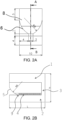
- FIG. 2A and FIG. 2B respectively show a front view and a side view of the crack evaluation device in a more specific embodiment.
- the body part 1 and the base part 2 extend in a longitudinal direction (length direction) with a predetermined length L, a height of 16 mm, and a width of 10 mm.
- the front curved surface 5 in an arcuate shape with a front curvature radius R of 8 mm is provided on the side opposite to the connecting part 3 at one end of the body part 1.
- the front curved surface 5 and the comb tooth part 4 are connected to each other via the stress concentration part 9.
- the front curved surface 5 in an arcuate shape rather than a straight line, a greater stress is caused to act on the stress concentration part 9 to make it more prone to cracking.
- the side curved surfaces 6 with a curvature radius R of 8 mm are provided on side surfaces of the longitudinal direction, on both sides of a short direction (width direction) at the other end of the body part 1.
- the side curved surfaces 6 are connected to the comb tooth part 4. Accordingly, since the width of the comb tooth part 4 can be narrowed to approximately 2 mm, the comb tooth part 4 is configured to be prone to cracking.
- the side planar surface 8 with a height of 5 mm on the side surface of the body part 1, the stress acting on the stress concentration part 9 side is increased to be prone to cracking.
- the length L of the body part 1 and the length L of the base part 2 may also be different from each other and may be designed as appropriate.
- the stress concentration part 9 may be designed as appropriate as long as the stress concentration part 9 is in a form at which a stress concentrates.
- the stress concentration part 9 may be configured as a narrow part, a concave groove shape, a V-shape, a U-shape, etc., but is preferably configured in a sharply cut notch shape (hereinafter described as a notch part as an example).
- FIG. 3 shows an A-B cross-section in FIG. 2A .
- the front curved surface 5 of the body part 1 and the planar surface of the base part 2 on the body part 1 side define a notch shape.
- the notch part 9 is provided at an end (lower end) of a connecting surface between the base part 2 and the comb tooth part 4.
- the position of the notch part 9 may also be provided at an end (upper end) of the connecting surface between the comb tooth part 4 and the body part 1.
- the notch part 9 may be configured at a position that serves as a starting point of cracking with respect to the comb tooth part 4 and at which a stress concentrates, and similar effects are achieved.
- FIG. 4 shows an enlarged cross-sectional view of a part C in FIG. 3 .
- the comb tooth part 4 is connected to each of the body part 1 and the base part 2 with a plurality of comb teeth 40.
- a plurality of slits (gaps) 41 with a width of 0.3 mm are provided from a position 0.3 mm away from the notch part 9 via the comb teeth 40 having a width of 0.3 mm.
- the crack sensitivity can also be evaluated in more detail using a stereo microscope based on the appearance of the additively manufactured object.
- the forms, pitches, widths, heights, etc., of the comb teeth and the slits may be changed in design as appropriate.
- the comb teeth may be provided in a plurality of rows in the longitudinal direction, or may be provided in two rows. In such cases, the comb teeth and the slits may be arranged alternately.
- the shape of the slit does not have to be a rectangular cuboid, and may also be changed as appropriate to a cylindrical shape, an elliptical cylindrical shape, a triangular prismatic shape, etc.
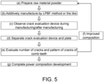
- FIG. 5 shows a flowchart of a crack evaluation method according to an embodiment of the disclosure.
- a crack pattern of the comb tooth part 4 mainly the number of cracks of the comb teeth 40, is observed when the crack evaluation device 10 described above is actually additively manufactured. Accordingly, a crack sensitivity of the raw material composition used in additive manufacturing can be evaluated, and the evaluation result can be fed back into the raw material composition to perform composition improvements and ultimately serve as a means for selecting a raw material composition that is less prone to cracking.
- a raw material powder of a predetermined composition is prepared (step a).
- prototyping is repeatedly performed with the predetermined composition, and the composition of the raw material powder is determined while making improvements.
- a crack evaluation device 10 is additively manufactured on a plate (step b).
- manufacturing conditions of the LPBF method are expressed by a formula (1) below as a correlation between a heat source energy density and manufacturing conditions.
- J P / v ⁇ a ⁇ t J: heat source energy density (J/mm 3 ), P: power of laser or electron beam (W), v: scanning speed (mm/s), a: scanning pitch (mm), t: layer thickness (mm)
- the heat source energy density J may be controlled by varying the power P of the laser or electron beam, the scanning speed v, the scanning pitch a, and the layer thickness t.
- the relationship with the power P of the laser or electron beam, the scanning speed v, and the scanning pitch a is significant as manufacturing parameters to be controlled, and the heat source energy density is preferably controlled by adjusting at least one of the three parameters.
- adjusting the scanning speed v is particularly effective and preferable.
- step c it is observed whether cracking does not occur at the comb tooth part 4 of the crack evaluation device 10 (step c). Specifically, since a tensile stress acts significantly during cooling, it is possible to confirm by visual inspection whether cracking occurs at the comb tooth part, which is the additively manufactured object after the additive manufacturing. At this stage, it is sufficient to simply confirm whether a crack is present, and it is not necessarily required to, for example, record and evaluate the number of cracked comb teeth. Further, although it is preferable to also observe cracking of the comb tooth part during the additive manufacturing process, at this stage as well, it is sufficient to simply confirm whether a crack is present.
- the observation process involves having an operator simply looking at the manufactured object during the additive manufacturing process or the cooling process thereafter with normal attention required during the manufacturing process, or simply observing a degree of warping or the like of the manufactured object during the cooling process, and the observation process may also be omitted.
- step d the crack evaluation device 10 and the plate are separated by wire cutting, and the crack evaluation device 10, which is the additively manufactured object, is taken out (step d).
- the number of cracks and the pattern of cracks of the comb teeth of the crack evaluation device 10 are observed and evaluated (step e).
- An analytical device capable of magnified observation such as a stereo microscope, is preferably used for the observation of cracks.
- the number of cracks of the comb teeth 40 is observed and the pattern of cracks is observed to evaluate the crack sensitivity of the raw material composition used.
- an evaluation means may perform evaluation simply based on the number of cracked comb teeth 40.
- the crack sensitivity may be evaluated based on a correlation between a crack length obtained from the number of cracked comb teeth 40 and a predetermined length of the body part.
- the design of the stress concentration part (notch part) 9 or the comb tooth part 4 may be changed, i.e., the acting stress may be varied, to evaluate the crack sensitivity from compositions prone to cracking to compositions less prone to cracking. Further, based on the correlation between the crack length obtained from the number of cracked comb teeth and the manufacturing conditions during additive manufacturing, appropriate manufacturing conditions can be identified to explore manufacturing conditions that are less prone to cracking. A case including such a process of exploring manufacturing conditions less prone to cracking is also included in the crack evaluation method of an additively manufactured object according to the disclosure.
- step f the evaluation result is reflected in the design of the raw material composition to obtain an improved composition and feed back to step (a) (step f).
- the embodiment including step f shows an example in which the evaluation result is fed back into the raw material composition to explore composition improvements.
- an improved composition is designed, the improved composition is used in a new additive manufacturing process to manufacture a new manufactured object, and a crack sensitivity of a crack evaluation device newly manufactured is evaluated to feed back a further improved composition.
- this step is repeated as appropriate, i.e., repeating composition improvement and evaluation, and development of a final powder composition is completed (step g).
- a case including such a process of exploring compositions less prone to cracking is also included in the crack evaluation method of an additively manufactured object according to the disclosure.
- at least one parameter among the power P of laser or electron beam, the scanning speed v, and the scanning pitch a is preferably adjusted to identify the optimal manufacturing conditions while performing evaluation.
- a crack evaluation device 10 in FIG. 1 was additively manufactured according to the LPBF method using a raw material powder having a composition of tool steel (JIS standard: SKD61) of an average particle diameter of 39 ⁇ m.
- a length L of the crack evaluation device 10 was set to 35 mm.
- Manufacturing conditions were as follows: Ar atmosphere manufacturing, a laser diameter of 75 ⁇ m, a layer thickness t of 30 ⁇ m, a scanning speed v of 1000 mm/s, a laser power P of 180 W, and a scanning pitch a of 0.05 mm.
- a crack sensitivity can be evaluated according to the number of cracked comb teeth. In other words, the larger the number of cracks, the higher the crack sensitivity. In the case of this example, the number of cracks observed from one side curved surface 6 was 32, and the number of cracks observed from the opposite side curved surface 6 was 33. Herein, the average value was taken to be 32.5.
- the crack evaluation device 10 is symmetrical with respect to its longitudinal direction, the number of cracks is preferably evaluated from both sides since the number of cracks may appear different.
- the method of Non-Patent Document 1 evaluates whether a crack is present, but the disclosure can further perform quantitative evaluation based on the number of cracked comb teeth in this manner.
- the correlation between the length L of the additively manufactured object of the crack evaluation device 10 and the crack length was investigated for each material type. Specifically, five compositions were compared, including tool steel, maraging steel, SUS316 stainless steel, SUS630 stainless steel, and alloy 718. Further, tool steel was manufactured in two atmospheres including Ar atmosphere and nitrogen atmosphere. The other compositions were manufactured only in Ar atmosphere. As the physical properties such as melting points differ for each composition, manufacturing conditions ensuring an internal void ratio of 0.1% or less were respectively selected. In the case of tool steel, the same manufacturing conditions were set as in Example 1, and the internal void ratio was 0.005%.
- FIG. 7 shows a relationship between the length L of the crack evaluation device (additively manufactured object) and the crack length of each alloy.
- the influence due to the length when the length L of the crack evaluation device 10 was set to 20 mm, 35 mm, and 50 mm was investigated on the horizontal axis.
- the vertical axis represents the crack length (mm).
- the crack length was a value obtained by counting, in magnification using a stereo microscope, the number of cracked comb teeth 40 from each side curved surface, and multiplying the average value of the numbers of cracked comb teeth by 0.6 mm. The average value was multiplied by 0.6 mm because the width of the comb tooth 40 was 0.3 mm and the width of the slit 41 was 0.3 mm, totaling to 0.6 mm.
- the relationship between the length L of the crack evaluation device and the evaluation of the crack sensitivity is compared using length as an indicator to make it easy to understand.
- the units of the length L of the crack evaluation device and the crack length are preferably unified as mm.
- the results in FIG. 7 show a tendency that as the length L of the manufactured object serving as the crack evaluation device 10 increases, cracking is more likely to occur. This is because the stress acting on the stress concentration part 9 due to deformation of the body part 1 increases. Thus, it can be said that designing the crack evaluation device 10 to be somewhat long makes it easier to evaluate the crack sensitivity. However, if the crack evaluation device 10 is configured to be too long, it will take more time for manufacturing, and more raw material powder will be required accordingly. Hence, the length L of the crack evaluation device is preferably approximately 20 to 50 mm.
- compositions showed a tendency that the crack length decreases and cracking is less likely to occur in a sequence from tool steel, SUS630 stainless steel, SUS316 stainless steel, alloy 718, to maraging steel. It is possible to quantitatively evaluate the crack sensitivity of each composition, which can be taken as a criterion for composition selection. Among them, with materials less prone to cracking such as SUS316 stainless steel and alloy 718, it has been difficult to detect occurrence of cracking itself using conventional methods. Thus, being capable of confirming cracking by visual inspection in this Example is extremely effective. Although occurrence of cracking could not be confirmed for maraging steel in this Example, it is possible to evaluate minute cracks by increasing the length of the crack evaluation device or adjusting the shape of the notch part or the spacing of the slit.
- the crack sensitivity can be compared. Accordingly, differences in the crack sensitivity due to composition differences can be quantitatively evaluated easily when developing materials of new compositions, and it is possible to apply to the development of materials of lower crack sensitivities.
- two types of powders were prepared, respectively with carbon contents of 0.35 mass% and 0.4 mass% as additive elements of tool steel, and crack evaluation devices 10 were manufactured under the same manufacturing conditions using the respective powders. Then, the crack sensitivity resulting from the carbon content can be compared by investigating the number of cracks of the respective comb teeth 40. By repeating this process and performing evaluation, the embodiment can be applied to composition development of tool steel of a low crack sensitivity.
- the composition of the raw material powder was tool steel (JIS standard: SKD61), with Ar atmosphere manufacturing, a laser diameter of 75 ⁇ m, a layer thickness t of 30 ⁇ m, a laser power P of 180 W, a scanning pitch a of 0.05 mm, a length L of 30 mm of the manufactured object, and a scanning speed v was varied from 600 to 1400 mm/s.
- FIG. 8 shows a relationship between the scanning speed and the crack length in the manufacturing of tool steel.
- the horizontal axis represents the scanning speed
- the vertical axis represents the crack length as in FIG. 7 .
- the crack length was high values of 18 to 20 mm.
- the crack length was contained to low values of 11 to 13 mm. Accordingly, it was learned that lower scanning speeds tend to lead to less cracking.
Landscapes
- Chemical & Material Sciences (AREA)
- Engineering & Computer Science (AREA)
- Materials Engineering (AREA)
- Mechanical Engineering (AREA)
- Metallurgy (AREA)
- Organic Chemistry (AREA)
- Manufacturing & Machinery (AREA)
- Physics & Mathematics (AREA)
- Analytical Chemistry (AREA)
- Pathology (AREA)
- Health & Medical Sciences (AREA)
- Biochemistry (AREA)
- General Health & Medical Sciences (AREA)
- General Physics & Mathematics (AREA)
- Immunology (AREA)
- Life Sciences & Earth Sciences (AREA)
- Plasma & Fusion (AREA)
- Investigating Strength Of Materials By Application Of Mechanical Stress (AREA)
- Investigating Or Analyzing Materials Using Thermal Means (AREA)
- Sampling And Sample Adjustment (AREA)
- Investigating And Analyzing Materials By Characteristic Methods (AREA)
- Powder Metallurgy (AREA)
Abstract
Description
- The disclosure relates to a crack evaluation method of an additively manufactured object and a crack evaluation device.
- Among additive manufacturing processes, in a laser powder bed fusion (LPBF) method involving repeatedly spreading a powder and selectively melting and solidifying the powder by laser, since the power is melted by laser and rapidly cooled and solidified to form a shape, a tensile stress tends to act on the manufactured object and cause cracking due to solidification shrinkage during rapid cooling and thermal contraction during post-manufacturing cooling. The susceptibility to cracking due to such a tensile stress, i.e., a crack sensitivity to thermal stress cracking, varies depending on the composition of the raw material powder, manufacturing conditions, and the shape of the manufactured object.
- To manufacture a product or a prototype using the LPBF method, it is desirable to evaluate and learn about the crack sensitivity in advance, and on this basis, select the composition of the raw material powder, the manufacturing conditions, the shape of the manufactured object, etc. Conventionally, methods for evaluating cracking include cutting a cross-section of the manufactured object and polishing the cut surface. However, such methods are time-consuming in evaluation.
- In the LPBF method, a complex three-dimensional manufactured object is manufactured by repeating a process of spreading a powder and selectively irradiating laser to melt and solidify the powder. The laser irradiated is very fine, with a diameter of 50 to 150 µm, and the laser is scanned at a high speed of 500 to 2000 mm/s. Thus, localized melting and solidification occur, a tensile stress tends to occur in the manufactured object due to solidification shrinkage and thermal contraction resulting from a temperature drop. When this stress exceeds a threshold, cracking occurs. Since the crack sensitivity varies depending on the composition of the powder, the manufacturing conditions, the shape of the manufactured object, etc., there has been a demand for a method to quantitatively and simply evaluate respective influences of these factors.
- As a simple method to evaluate the crack sensitivity, in Non-Patent
Document 1, a notch is provided at a manufactured object to make it more prone to cracking, and manufacturing conditions are changed to evaluate whether a crack is present. - [Non-Patent Document 1] Residual Stress Relief Technology Using Phase Transformation in Metal Additive Manufacturing: Journal of Smart Processing, Vol. 10, No. 4 (July 2021), pp. 163-170
- The crack evaluation method disclosed in Non-Patent
Document 1 proposes an evaluation shape for a crack based on the LPBF method, but the evaluation is performed based on the pattern of crack by visual inspection, and quantitative evaluation is difficult. For example, compositions prone to cracking, such as martensitic stainless steel, can be evaluated, but compositions less prone to cracking cannot be evaluated. - Thus, it is an objective of the disclosure to provide a crack evaluation method and a crack evaluation device capable of quantitatively evaluating a crack sensitivity (hereinafter referred to as a "crack sensitivity") to thermal stress cracking of a manufactured object manufactured by additive manufacturing such as an LPBF method, and capable of evaluating even compositions less prone to cracking.
- The disclosure provides a crack evaluation method of an additively manufactured object, which is a method evaluating a crack sensitivity of an additively manufactured object. The crack evaluation method includes the following. A crack evaluation device is additively manufactured using a raw material powder. The crack evaluation device includes: a body part, a base part opposed to the body part, a connecting part connecting one end side of the body part and the base part, a stress concentration part connecting another end side of the body part and the base part, and a comb tooth part connecting, by comb teeth, the body part and the base part between the connecting part and the stress concentration part. The crack sensitivity is evaluated based on cracked comb teeth at the crack evaluation device serving as the additively manufactured object.
- Accordingly, even with an additively manufactured object of which a crack sensitivity is unknown, the crack sensitivity can be quantitatively evaluated based on the number of cracked comb teeth. In the disclosure, defects such as cracks and fissures are collectively referred to as "cracks".
- The evaluating may include evaluating the crack sensitivity based on a relationship between a crack length obtained from a quantity of cracked comb teeth and a length of the body part along an arrangement direction of the comb teeth.
- Accordingly, even with a manufactured object of a composition less prone to cracking, the crack sensitivity can be evaluated.
- The evaluating may include deriving manufacturing conditions for a lower crack sensitivity based on a correlation between a crack length obtained from a quantity of cracked comb teeth and manufacturing conditions.
- Accordingly, manufacturing conditions less prone to cracking can be explored and selected.
- Furthermore, an improved composition with a lower crack sensitivity may be derived based on an evaluation result obtained in the evaluating, the improved composition may be used in the additively manufacturing, the crack sensitivity of the manufactured crack evaluation device may be evaluated, and composition improvement and evaluation of the crack sensitivity may be subsequently repeated to derive a composition with a lower crack sensitivity.
- Accordingly, compositions less prone to cracking can be explored and selected.
- Further, the disclosure provides a crack evaluation device evaluating a crack sensitivity of an additively manufactured object. The crack evaluation device includes: a body part, a base part opposed to the body part, a connecting part connecting one end side of the body part and the base part, a stress concentration part connecting another end side of the body part and the base part, and a comb tooth part connecting, by comb teeth, the body part and the base part between the connecting part and the stress concentration part.
- In a preferred shape of the crack evaluation device, a front curved surface may be provided at the another end side of the body part, side curved surfaces may be provided on both sides of the front curved surface, and the front curved surface of the body part and the comb tooth part may be connected to each other via the stress concentration part.
- According to the disclosure, it is possible to quantitatively evaluate a crack sensitivity to thermal stress cracking of a manufactured object manufactured by additive manufacturing. Further, manufacturing conditions less prone to cracking and compositions less prone to cracking can be explored and selected.
-
-
FIG. 1 is a perspective view of a crack evaluation device. -
FIG. 2A and FIG. 2B are respectively a front view and a side view of the crack evaluation device. -
FIG. 3 is a cross-sectional view taken along line A-B inFIG. 2A . -
FIG. 4 is an enlarged cross-sectional view of a part C inFIG. 3 . -
FIG. 5 is a flowchart of a crack evaluation method. -
FIG. 6 is a side view photograph showing a cracked state at a comb tooth part after manufacturing of a crack evaluation device. -
FIG. 7 is a graph showing a relationship between a length of a crack evaluation device (additively manufactured object) and a crack length of various alloys. -
FIG. 8 is a graph showing a relationship between a scanning speed and a crack length in manufacturing of tool steel. - Hereinafter, embodiments of the disclosure will be described with reference to the drawings.
-
FIG. 1 shows a perspective view of acrack evaluation device 10 according to an embodiment. Thecrack evaluation device 10 is an additively manufactured object composed of abody part 1, abase part 2, a connectingpart 3, and acomb tooth part 4. Additive manufacturing is performed toward an upward side on the paper surface. First, thebase part 2 is manufactured, then thecomb tooth part 4 and the connectingpart 3 are manufactured, and finally thebody part 1 is manufactured. In this embodiment, thebody part 1 has a frontcurved surface 5, sidecurved surfaces 6 on both sides of the frontcurved surface 5, an upperplanar surface 7, and a sideplanar surface 8. Thebody part 1 is in a shape in which the frontcurved surface 5 and the sidecurved surfaces 6 are tapered toward thebase part 2. Further, thebase part 2 has a flat plate shape. Thebody part 1 and thebase part 2 are opposed to each other. One end between thebody part 1 and thebase part 2 is connected by the connectingpart 3, and the other end is connected by astress concentration part 9 connected from the frontcurved surface 5 at thebody part 1. Between the connectingpart 3 and thestress concentration part 9, thebody part 1 and thebase part 2 are connected by thecomb tooth part 4 composed of a plurality ofcomb teeth 40 with a predetermined gap present therebetween. That is, the connectingpart 3, thecomb tooth part 4, and thestress concentrating part 9, which are integrally formed, are disposed in a straight line shape in this sequence. With such a structure, during additive manufacturing and/or during cooling to room temperature after manufacturing, when thebody part 1 contracts and thebody part 1 deforms into a curved shape in a longitudinal direction, since one side in the longitudinal direction is fixed by the connectingpart 3, stress is concentrated at the stress concentration part 9 (also referred to as a notch forming part) formed by a notch, and this position serves as a starting point for thecomb teeth 40 at the end to crack and separate. As deformation progresses further,adjacent comb teeth 40 also crack, and cracking of thecomb tooth part 4 progresses. On the other hand, the connectingpart 3, which does not include a gap as thecomb tooth part 4, is provided on the opposite side of thestress concentration part 9, so cracking is prevented from occurring from thecomb teeth 40 in the vicinity of the connectingpart 3. Accordingly, a composition of a low crack sensitivity will have fewer cracked comb teeth, and a composition of a high crack sensitivity will have more cracked comb teeth. In this manner, even with an additively manufactured object of which a crack sensitivity is unknown, the crack sensitivity can be evaluated based on the number of cracked comb teeth. -
FIG. 2A and FIG. 2B respectively show a front view and a side view of the crack evaluation device in a more specific embodiment. Thebody part 1 and thebase part 2 extend in a longitudinal direction (length direction) with a predetermined length L, a height of 16 mm, and a width of 10 mm. The frontcurved surface 5 in an arcuate shape with a front curvature radius R of 8 mm is provided on the side opposite to the connectingpart 3 at one end of thebody part 1. The frontcurved surface 5 and thecomb tooth part 4 are connected to each other via thestress concentration part 9. By configuring the frontcurved surface 5 in an arcuate shape rather than a straight line, a greater stress is caused to act on thestress concentration part 9 to make it more prone to cracking. Further, the side curvedsurfaces 6 with a curvature radius R of 8 mm are provided on side surfaces of the longitudinal direction, on both sides of a short direction (width direction) at the other end of thebody part 1. At a lower part, the side curvedsurfaces 6 are connected to thecomb tooth part 4. Accordingly, since the width of thecomb tooth part 4 can be narrowed to approximately 2 mm, thecomb tooth part 4 is configured to be prone to cracking. Further, by providing the sideplanar surface 8 with a height of 5 mm on the side surface of thebody part 1, the stress acting on thestress concentration part 9 side is increased to be prone to cracking. The length L of thebody part 1 and the length L of thebase part 2 may also be different from each other and may be designed as appropriate. - Further, the
stress concentration part 9 may be designed as appropriate as long as thestress concentration part 9 is in a form at which a stress concentrates. For example, thestress concentration part 9 may be configured as a narrow part, a concave groove shape, a V-shape, a U-shape, etc., but is preferably configured in a sharply cut notch shape (hereinafter described as a notch part as an example).FIG. 3 shows an A-B cross-section inFIG. 2A . The frontcurved surface 5 of thebody part 1 and the planar surface of thebase part 2 on thebody part 1 side define a notch shape. Thenotch part 9 is provided at an end (lower end) of a connecting surface between thebase part 2 and thecomb tooth part 4. The position of thenotch part 9 may also be provided at an end (upper end) of the connecting surface between thecomb tooth part 4 and thebody part 1. In other words, thenotch part 9 may be configured at a position that serves as a starting point of cracking with respect to thecomb tooth part 4 and at which a stress concentrates, and similar effects are achieved. - Next,
FIG. 4 shows an enlarged cross-sectional view of a part C inFIG. 3 . Thecomb tooth part 4 is connected to each of thebody part 1 and thebase part 2 with a plurality ofcomb teeth 40. Herein, a plurality of slits (gaps) 41 with a width of 0.3 mm are provided from a position 0.3 mm away from thenotch part 9 via thecomb teeth 40 having a width of 0.3 mm. By providing theslits 41, cracking is more likely to occur at thecomb tooth part 4, and cracking can occur and can be evaluated even with a composition of a low crack sensitivity. Further, by counting the number of cracked comb teeth from the appearance, quantitative evaluation can be easily performed. Further, the crack sensitivity can also be evaluated in more detail using a stereo microscope based on the appearance of the additively manufactured object. The forms, pitches, widths, heights, etc., of the comb teeth and the slits may be changed in design as appropriate. For example, the comb teeth may be provided in a plurality of rows in the longitudinal direction, or may be provided in two rows. In such cases, the comb teeth and the slits may be arranged alternately. Further, the shape of the slit does not have to be a rectangular cuboid, and may also be changed as appropriate to a cylindrical shape, an elliptical cylindrical shape, a triangular prismatic shape, etc. -
FIG. 5 shows a flowchart of a crack evaluation method according to an embodiment of the disclosure. In the crack evaluation method, a crack pattern of thecomb tooth part 4, mainly the number of cracks of thecomb teeth 40, is observed when thecrack evaluation device 10 described above is actually additively manufactured. Accordingly, a crack sensitivity of the raw material composition used in additive manufacturing can be evaluated, and the evaluation result can be fed back into the raw material composition to perform composition improvements and ultimately serve as a means for selecting a raw material composition that is less prone to cracking. - First, a raw material powder of a predetermined composition is prepared (step a). When additively manufacturing a product having new properties, prototyping is repeatedly performed with the predetermined composition, and the composition of the raw material powder is determined while making improvements.
- Then, using a method such as LPBF, a
crack evaluation device 10 is additively manufactured on a plate (step b). At this time, manufacturing conditions of the LPBF method are expressed by a formula (1) below as a correlation between a heat source energy density and manufacturing conditions.
- Thus, the heat source energy density J may be controlled by varying the power P of the laser or electron beam, the scanning speed v, the scanning pitch a, and the layer thickness t. The relationship with the power P of the laser or electron beam, the scanning speed v, and the scanning pitch a is significant as manufacturing parameters to be controlled, and the heat source energy density is preferably controlled by adjusting at least one of the three parameters. Among these, adjusting the scanning speed v is particularly effective and preferable.
- Next, during the additive manufacturing process and/or a cooling process after the additive manufacturing, it is observed whether cracking does not occur at the
comb tooth part 4 of the crack evaluation device 10 (step c). Specifically, since a tensile stress acts significantly during cooling, it is possible to confirm by visual inspection whether cracking occurs at the comb tooth part, which is the additively manufactured object after the additive manufacturing. At this stage, it is sufficient to simply confirm whether a crack is present, and it is not necessarily required to, for example, record and evaluate the number of cracked comb teeth. Further, although it is preferable to also observe cracking of the comb tooth part during the additive manufacturing process, at this stage as well, it is sufficient to simply confirm whether a crack is present. In other words, the observation process involves having an operator simply looking at the manufactured object during the additive manufacturing process or the cooling process thereafter with normal attention required during the manufacturing process, or simply observing a degree of warping or the like of the manufactured object during the cooling process, and the observation process may also be omitted. - Next, the
crack evaluation device 10 and the plate are separated by wire cutting, and thecrack evaluation device 10, which is the additively manufactured object, is taken out (step d). - Next, the number of cracks and the pattern of cracks of the comb teeth of the
crack evaluation device 10 are observed and evaluated (step e). An analytical device capable of magnified observation, such as a stereo microscope, is preferably used for the observation of cracks. In this process, the number of cracks of thecomb teeth 40 is observed and the pattern of cracks is observed to evaluate the crack sensitivity of the raw material composition used. For example, an evaluation means may perform evaluation simply based on the number of crackedcomb teeth 40. Further, the crack sensitivity may be evaluated based on a correlation between a crack length obtained from the number of crackedcomb teeth 40 and a predetermined length of the body part. At this time, the design of the stress concentration part (notch part) 9 or thecomb tooth part 4 may be changed, i.e., the acting stress may be varied, to evaluate the crack sensitivity from compositions prone to cracking to compositions less prone to cracking. Further, based on the correlation between the crack length obtained from the number of cracked comb teeth and the manufacturing conditions during additive manufacturing, appropriate manufacturing conditions can be identified to explore manufacturing conditions that are less prone to cracking. A case including such a process of exploring manufacturing conditions less prone to cracking is also included in the crack evaluation method of an additively manufactured object according to the disclosure. - Then, the evaluation result is reflected in the design of the raw material composition to obtain an improved composition and feed back to step (a) (step f). The embodiment including step f shows an example in which the evaluation result is fed back into the raw material composition to explore composition improvements. Thus, based on the evaluation result obtained in the evaluation process, an improved composition is designed, the improved composition is used in a new additive manufacturing process to manufacture a new manufactured object, and a crack sensitivity of a crack evaluation device newly manufactured is evaluated to feed back a further improved composition. Hereinafter, this step is repeated as appropriate, i.e., repeating composition improvement and evaluation, and development of a final powder composition is completed (step g). A case including such a process of exploring compositions less prone to cracking is also included in the crack evaluation method of an additively manufactured object according to the disclosure. At this time, at least one parameter among the power P of laser or electron beam, the scanning speed v, and the scanning pitch a is preferably adjusted to identify the optimal manufacturing conditions while performing evaluation.
- The disclosure will be specifically described below based on Examples.
- A
crack evaluation device 10 inFIG. 1 was additively manufactured according to the LPBF method using a raw material powder having a composition of tool steel (JIS standard: SKD61) of an average particle diameter of 39 µm. A length L of thecrack evaluation device 10 was set to 35 mm. Manufacturing conditions were as follows: Ar atmosphere manufacturing, a laser diameter of 75 µm, a layer thickness t of 30 µm, a scanning speed v of 1000 mm/s, a laser power P of 180 W, and a scanning pitch a of 0.05 mm. As a result, warping occurred at thebody part 1, and cracking occurred at thecomb tooth part 4 in the vicinity of thebase part 2.FIG. 6 shows a side view photograph of the crack evaluation device (additively manufactured object) after cooling. A crack sensitivity can be evaluated according to the number of cracked comb teeth. In other words, the larger the number of cracks, the higher the crack sensitivity. In the case of this example, the number of cracks observed from one side curvedsurface 6 was 32, and the number of cracks observed from the opposite side curvedsurface 6 was 33. Herein, the average value was taken to be 32.5. Although thecrack evaluation device 10 is symmetrical with respect to its longitudinal direction, the number of cracks is preferably evaluated from both sides since the number of cracks may appear different. The method ofNon-Patent Document 1 evaluates whether a crack is present, but the disclosure can further perform quantitative evaluation based on the number of cracked comb teeth in this manner. - The correlation between the length L of the additively manufactured object of the
crack evaluation device 10 and the crack length was investigated for each material type. Specifically, five compositions were compared, including tool steel, maraging steel, SUS316 stainless steel, SUS630 stainless steel, and alloy 718. Further, tool steel was manufactured in two atmospheres including Ar atmosphere and nitrogen atmosphere. The other compositions were manufactured only in Ar atmosphere. As the physical properties such as melting points differ for each composition, manufacturing conditions ensuring an internal void ratio of 0.1% or less were respectively selected. In the case of tool steel, the same manufacturing conditions were set as in Example 1, and the internal void ratio was 0.005%.FIG. 7 shows a relationship between the length L of the crack evaluation device (additively manufactured object) and the crack length of each alloy. The influence due to the length when the length L of thecrack evaluation device 10 was set to 20 mm, 35 mm, and 50 mm was investigated on the horizontal axis. The vertical axis represents the crack length (mm). Herein, the crack length was a value obtained by counting, in magnification using a stereo microscope, the number of crackedcomb teeth 40 from each side curved surface, and multiplying the average value of the numbers of cracked comb teeth by 0.6 mm. The average value was multiplied by 0.6 mm because the width of thecomb tooth 40 was 0.3 mm and the width of theslit 41 was 0.3 mm, totaling to 0.6 mm. In this example, the relationship between the length L of the crack evaluation device and the evaluation of the crack sensitivity is compared using length as an indicator to make it easy to understand. Thus, the units of the length L of the crack evaluation device and the crack length are preferably unified as mm. - The results in
FIG. 7 show a tendency that as the length L of the manufactured object serving as thecrack evaluation device 10 increases, cracking is more likely to occur. This is because the stress acting on thestress concentration part 9 due to deformation of thebody part 1 increases. Thus, it can be said that designing thecrack evaluation device 10 to be somewhat long makes it easier to evaluate the crack sensitivity. However, if thecrack evaluation device 10 is configured to be too long, it will take more time for manufacturing, and more raw material powder will be required accordingly. Hence, the length L of the crack evaluation device is preferably approximately 20 to 50 mm. - Further, the comparison of compositions showed a tendency that the crack length decreases and cracking is less likely to occur in a sequence from tool steel, SUS630 stainless steel, SUS316 stainless steel, alloy 718, to maraging steel. It is possible to quantitatively evaluate the crack sensitivity of each composition, which can be taken as a criterion for composition selection. Among them, with materials less prone to cracking such as SUS316 stainless steel and alloy 718, it has been difficult to detect occurrence of cracking itself using conventional methods. Thus, being capable of confirming cracking by visual inspection in this Example is extremely effective. Although occurrence of cracking could not be confirmed for maraging steel in this Example, it is possible to evaluate minute cracks by increasing the length of the crack evaluation device or adjusting the shape of the notch part or the spacing of the slit.
- By evaluating the number of cracked comb teeth of each crack evaluation device according to a plurality of compositions as described above, the crack sensitivity can be compared. Accordingly, differences in the crack sensitivity due to composition differences can be quantitatively evaluated easily when developing materials of new compositions, and it is possible to apply to the development of materials of lower crack sensitivities. For example, two types of powders were prepared, respectively with carbon contents of 0.35 mass% and 0.4 mass% as additive elements of tool steel, and crack
evaluation devices 10 were manufactured under the same manufacturing conditions using the respective powders. Then, the crack sensitivity resulting from the carbon content can be compared by investigating the number of cracks of therespective comb teeth 40. By repeating this process and performing evaluation, the embodiment can be applied to composition development of tool steel of a low crack sensitivity. - Further, in the case of Ar atmosphere manufacturing and nitrogen atmosphere manufacturing of tool steel, there was a tendency that the nitrogen atmosphere contributes to a higher crack sensitivity. This indicates that it is also possible to compare differences due to atmospheric gases. For example, if reducing the crack sensitivity is prioritized, manufacturing may be performed using Ar gas which is more expensive. Conversely, if a higher crack sensitivity does not pose a problem to the properties of the manufactured object, nitrogen gas which is less expensive may be used, allowing for the selective application of atmospheric gases for manufacturing and the like.
- Next, a correlation between the crack length and the manufacturing conditions was investigated. Specifically, the composition of the raw material powder was tool steel (JIS standard: SKD61), with Ar atmosphere manufacturing, a laser diameter of 75 µm, a layer thickness t of 30 µm, a laser power P of 180 W, a scanning pitch a of 0.05 mm, a length L of 30 mm of the manufactured object, and a scanning speed v was varied from 600 to 1400 mm/s.
FIG. 8 shows a relationship between the scanning speed and the crack length in the manufacturing of tool steel. The horizontal axis represents the scanning speed, and the vertical axis represents the crack length as inFIG. 7 . As a result, at high scanning speeds of 1000 to 1400 mm/s, the crack length was high values of 18 to 20 mm. On the other hand, at low scanning speeds of 800 to 600 mm/s, the crack length was contained to low values of 11 to 13 mm. Accordingly, it was learned that lower scanning speeds tend to lead to less cracking. In addition to the scanning speed, it is also considered possible to identify manufacturing conditions that suppress the crack length by operating the power P of laser or electron beam or the scanning pitch a. In this manner, the disclosure can be used for the selection of manufacturing conditions that suppress cracking. - 1: body part, 2: base part, 3: connecting part, 4: comb tooth part, 5: front curved surface, 6: side curved surface, 7: upper planar surface, 8: side planar surface, 9: stress concentration part (notch part), 10: crack evaluation device, 40: comb tooth, 41: slit (gap)
Claims (6)
- A crack evaluation method of an additively manufactured object, which is a method evaluating a crack sensitivity of an additively manufactured object, the crack evaluation method comprising:additively manufacturing a crack evaluation device (10) using a raw material powder, the crack evaluation device (10) comprising: a body part (1), a base part (2) opposed to the body part (1), a connecting part (3) connecting one end side of the body part (1) and the base part (2), a stress concentration part (9) connecting another end side of the body part (1) and the base part (2), and a comb tooth part (4) connecting, by comb teeth (40), the body part (1) and the base part (2) between the connecting part (3) and the stress concentration part (9); andevaluating the crack sensitivity based on cracked comb teeth (40) at the crack evaluation device (10) serving as the additively manufactured object.
- The crack evaluation method of an additively manufactured object according to claim 1, wherein the evaluating comprises evaluating the crack sensitivity based on a relationship between a crack length obtained from a quantity of cracked comb teeth (40) and a length of the body part (1) along an arrangement direction of the comb teeth (40).
- The crack evaluation method of an additively manufactured object according to claim 1 or 2, wherein the evaluating comprises deriving manufacturing conditions for a lower crack sensitivity based on a correlation between a crack length obtained from a quantity of cracked comb teeth (40) and manufacturing conditions.
- The crack evaluation method of an additively manufactured object according to claim 1 or 2, wherein an improved composition with a lower crack sensitivity is derived based on an evaluation result obtained in the evaluating, the improved composition is used in the additively manufacturing, the crack sensitivity of the manufactured crack evaluation device (10) is evaluated, and composition improvement and evaluation of the crack sensitivity are subsequently repeated to derive a composition with a lower crack sensitivity.
- A crack evaluation device (10) evaluating a crack sensitivity of an additively manufactured object, the crack evaluation device (10) comprising:
a body part (1), a base part (2) opposed to the body part (1), a connecting part (3) connecting one end side of the body part (1) and the base part (2), a stress concentration part (9) connecting another end side of the body part (1) and the base part (2), and a comb tooth part (4) connecting, by comb teeth (40), the body part (1) and the base part (2) between the connecting part (3) and the stress concentration part (9). - The crack evaluation device (10) according to claim 5, wherein a front curved surface (5) is provided at the another end side of the body part (1), side curved surfaces (6) are provided on both sides of the front curved surface (5), and the front curved surface (5) of the body part (1) and the comb tooth part (4) are connected to each other via the stress concentration part (9).
Applications Claiming Priority (1)
| Application Number | Priority Date | Filing Date | Title |
|---|---|---|---|
| JP2023133129 | 2023-08-17 |
Publications (3)
| Publication Number | Publication Date |
|---|---|
| EP4509248A2 true EP4509248A2 (en) | 2025-02-19 |
| EP4509248A3 EP4509248A3 (en) | 2025-03-19 |
| EP4509248B1 EP4509248B1 (en) | 2026-03-18 |
Family
ID=92300709
Family Applications (1)
| Application Number | Title | Priority Date | Filing Date |
|---|---|---|---|
| EP24193773.9A Active EP4509248B1 (en) | 2023-08-17 | 2024-08-09 | Crack evaluation method of additively manufactured object and crack evaluation device |
Country Status (3)
| Country | Link |
|---|---|
| US (1) | US20250060315A1 (en) |
| EP (1) | EP4509248B1 (en) |
| JP (1) | JP2025028001A (en) |
Families Citing this family (1)
| Publication number | Priority date | Publication date | Assignee | Title |
|---|---|---|---|---|
| CN121410035A (en) * | 2025-12-29 | 2026-01-27 | 钢研国际新材料创新中心(深圳)有限公司 | A method for evaluating the suitability of high-temperature alloy additive manufacturing |
Family Cites Families (5)
| Publication number | Priority date | Publication date | Assignee | Title |
|---|---|---|---|---|
| CN110570512B (en) * | 2018-06-06 | 2024-02-02 | 哈米尔顿森德斯特兰德公司 | Additive manufacturing including a compensation modeling method using shape transformation |
| CN108817386B (en) * | 2018-06-29 | 2020-02-14 | 西北工业大学 | Interlayer comb-shaped splicing method for multi-beam laser selective melting forming |
| CN116940428A (en) * | 2021-03-18 | 2023-10-24 | 株式会社博迈立铖 | Metal powder for laminated molding and laminated molded article using same |
| JPWO2023068268A1 (en) * | 2021-10-19 | 2023-04-27 | ||
| JP7347715B1 (en) * | 2021-11-04 | 2023-09-20 | 株式会社プロテリアル | Dimensional quality evaluation method and evaluation system for additively manufactured objects |
-
2024
- 2024-08-07 JP JP2024131196A patent/JP2025028001A/en active Pending
- 2024-08-09 EP EP24193773.9A patent/EP4509248B1/en active Active
- 2024-08-13 US US18/803,547 patent/US20250060315A1/en active Pending
Non-Patent Citations (1)
| Title |
|---|
| "Residual Stress Relief Technology Using Phase Transformation in Metal Additive Manufacturing", JOURNAL OF SMART PROCESSING, vol. 10, no. 4, July 2021 (2021-07-01), pages 163 - 170 |
Also Published As
| Publication number | Publication date |
|---|---|
| EP4509248A3 (en) | 2025-03-19 |
| EP4509248B1 (en) | 2026-03-18 |
| JP2025028001A (en) | 2025-02-28 |
| US20250060315A1 (en) | 2025-02-20 |
Similar Documents
| Publication | Publication Date | Title |
|---|---|---|
| Gockel et al. | The influence of additive manufacturing processing parameters on surface roughness and fatigue life | |
| EP4140620A1 (en) | Method for prefabricating air hole defect by means of controlled slm process | |
| Matilainen et al. | Characterization of process efficiency improvement in laser additive manufacturing | |
| Stoudt et al. | Location-specific microstructure characterization within IN625 additive manufacturing benchmark test artifacts | |
| EP4509248B1 (en) | Crack evaluation method of additively manufactured object and crack evaluation device | |
| Zhao et al. | Effects of microstructure anisotropy on dynamic fracture behaviors of a selective laser melting nickel-based superalloy | |
| US11348378B2 (en) | Test specimen for validating operating parameters of a method for the additive manufacturing of a part by laser melting on powder beds | |
| Busi et al. | Nondestructive characterization of laser powder bed fusion parts with neutron Bragg edge imaging | |
| Fardan et al. | Microstructure tailoring for crack mitigation in CM247LC manufactured by powder bed fusion–Laser beam | |
| Makiewicz | Development of simultaneous transformation kinetics microstructure model with application to laser metal deposited Ti-6Al-4V and alloy 718 | |
| Hytönen et al. | Study of fusion boundary microstructure and local mismatch of SA508/alloy 52 dissimilar metal weld with buttering | |
| EP3712601B1 (en) | Method for measuring degree of recrystallization of zirconium alloy cladding tube for nuclear fuel by using ebsd pattern quality | |
| Tarafder et al. | Assessing the effect of scan strategies on the structure-property relationship in electron beam powder bed fusion processed 316L stainless steel | |
| Bemani et al. | Rapid fatigue evaluation of additive manufactured specimens: Application to stainless steel AISI 316L obtained by laser metal powder bed fusion | |
| Tsai et al. | Correlating energy density induced residual stress, porosity, and mechanical property variations in directed energy deposition using neutron diffraction and imaging techniques | |
| Sun et al. | Microstructure evolution and mechanical properties of Ti-6Al-4V alloy prepared by fused filament fabrication | |
| Kruska et al. | Characterization of stress corrosion cracking initiation precursors in cold-worked alloy 690 using advanced high-resolution microscopy | |
| Berthel et al. | Geometric deviations and their effects in thin-plate lattice structures fabricated via LPBF | |
| US20260002237A1 (en) | Methodologies for Formulating Compositions, Including Aluminum Alloys with High-Temperature Strength | |
| US12422424B1 (en) | Additive manufacturing test method for metallic alloy compositions and methods of making the same | |
| Lim et al. | On the interplay of internal voids, mechanical properties, and residual stresses in additively manufactured Haynes 282 | |
| Hatos | Improvement of the cantilever test geometry deflection measurement method to assess residual stresses in laser powder bed fusion | |
| Keran et al. | In-crystal dislocation behaviour and hardness changes in the case of severe plastic deformation of aluminium samples | |
| Sprengel | Study on the determination and the assessment of the residual stress in laser powder bed fused stainless steel structures | |
| EP4289982B1 (en) | Ni-based alloy powder for additive manufacturing, additive manufactured component, and additive manufacturing method thereof |
Legal Events
| Date | Code | Title | Description |
|---|---|---|---|
| PUAI | Public reference made under article 153(3) epc to a published international application that has entered the european phase |
Free format text: ORIGINAL CODE: 0009012 |
|
| STAA | Information on the status of an ep patent application or granted ep patent |
Free format text: STATUS: REQUEST FOR EXAMINATION WAS MADE |
|
| PUAL | Search report despatched |
Free format text: ORIGINAL CODE: 0009013 |
|
| 17P | Request for examination filed |
Effective date: 20240809 |
|
| AK | Designated contracting states |
Kind code of ref document: A2 Designated state(s): AL AT BE BG CH CY CZ DE DK EE ES FI FR GB GR HR HU IE IS IT LI LT LU LV MC ME MK MT NL NO PL PT RO RS SE SI SK SM TR |
|
| AK | Designated contracting states |
Kind code of ref document: A3 Designated state(s): AL AT BE BG CH CY CZ DE DK EE ES FI FR GB GR HR HU IE IS IT LI LT LU LV MC ME MK MT NL NO PL PT RO RS SE SI SK SM TR |
|
| RIC1 | Information provided on ipc code assigned before grant |
Ipc: C22C 33/02 20060101ALN20250210BHEP Ipc: B33Y 50/02 20150101ALN20250210BHEP Ipc: B22F 10/36 20210101ALN20250210BHEP Ipc: B22F 10/32 20210101ALN20250210BHEP Ipc: G01N 3/08 20060101ALI20250210BHEP Ipc: B33Y 10/00 20150101ALI20250210BHEP Ipc: B33Y 80/00 20150101ALI20250210BHEP Ipc: B22F 10/28 20210101ALI20250210BHEP Ipc: B22F 5/10 20060101AFI20250210BHEP |
|
| RIC1 | Information provided on ipc code assigned before grant |
Ipc: B22F 5/10 20060101AFI20251106BHEP Ipc: B22F 10/28 20210101ALI20251106BHEP Ipc: B33Y 80/00 20150101ALI20251106BHEP Ipc: B33Y 10/00 20150101ALI20251106BHEP Ipc: G01N 3/08 20060101ALI20251106BHEP Ipc: B22F 10/32 20210101ALN20251106BHEP Ipc: B22F 10/36 20210101ALN20251106BHEP Ipc: B33Y 50/02 20150101ALN20251106BHEP Ipc: C22C 33/02 20060101ALN20251106BHEP |
|
| GRAP | Despatch of communication of intention to grant a patent |
Free format text: ORIGINAL CODE: EPIDOSNIGR1 |
|
| STAA | Information on the status of an ep patent application or granted ep patent |
Free format text: STATUS: GRANT OF PATENT IS INTENDED |
|
| RIC1 | Information provided on ipc code assigned before grant |
Ipc: B22F 5/10 20060101AFI20251120BHEP Ipc: B22F 10/28 20210101ALI20251120BHEP Ipc: B33Y 80/00 20150101ALI20251120BHEP Ipc: B33Y 10/00 20150101ALI20251120BHEP Ipc: G01N 3/08 20060101ALI20251120BHEP Ipc: B22F 10/32 20210101ALN20251120BHEP Ipc: B22F 10/36 20210101ALN20251120BHEP Ipc: B33Y 50/02 20150101ALN20251120BHEP Ipc: C22C 33/02 20060101ALN20251120BHEP |
|
| INTG | Intention to grant announced |
Effective date: 20251219 |
|
| GRAS | Grant fee paid |
Free format text: ORIGINAL CODE: EPIDOSNIGR3 |
|
| GRAA | (expected) grant |
Free format text: ORIGINAL CODE: 0009210 |
|
| STAA | Information on the status of an ep patent application or granted ep patent |
Free format text: STATUS: THE PATENT HAS BEEN GRANTED |
|
| P01 | Opt-out of the competence of the unified patent court (upc) registered |
Free format text: CASE NUMBER: UPC_APP_0002327_4509248/2026 Effective date: 20260122 |
|
| AK | Designated contracting states |
Kind code of ref document: B1 Designated state(s): AL AT BE BG CH CY CZ DE DK EE ES FI FR GB GR HR HU IE IS IT LI LT LU LV MC ME MK MT NL NO PL PT RO RS SE SI SK SM TR |
|
| REG | Reference to a national code |
Ref country code: CH Ref legal event code: F10 Free format text: ST27 STATUS EVENT CODE: U-0-0-F10-F00 (AS PROVIDED BY THE NATIONAL OFFICE) Effective date: 20260318 Ref country code: GB Ref legal event code: FG4D |
|
| REG | Reference to a national code |
Ref country code: DE Ref legal event code: R096 Ref document number: 602024003269 Country of ref document: DE |
|
| REG | Reference to a national code |
Ref country code: IE Ref legal event code: FG4D |
|
| PG25 | Lapsed in a contracting state [announced via postgrant information from national office to epo] |
Ref country code: RS Free format text: LAPSE BECAUSE OF FAILURE TO SUBMIT A TRANSLATION OF THE DESCRIPTION OR TO PAY THE FEE WITHIN THE PRESCRIBED TIME-LIMIT Effective date: 20260618 |
|
| PG25 | Lapsed in a contracting state [announced via postgrant information from national office to epo] |
Ref country code: GR Free format text: LAPSE BECAUSE OF FAILURE TO SUBMIT A TRANSLATION OF THE DESCRIPTION OR TO PAY THE FEE WITHIN THE PRESCRIBED TIME-LIMIT Effective date: 20260619 |
|
| REG | Reference to a national code |
Ref country code: LT Ref legal event code: MG9D |
|
| PG25 | Lapsed in a contracting state [announced via postgrant information from national office to epo] |
Ref country code: LT Free format text: LAPSE BECAUSE OF FAILURE TO SUBMIT A TRANSLATION OF THE DESCRIPTION OR TO PAY THE FEE WITHIN THE PRESCRIBED TIME-LIMIT Effective date: 20260318 |
|
| PG25 | Lapsed in a contracting state [announced via postgrant information from national office to epo] |
Ref country code: NO Free format text: LAPSE BECAUSE OF FAILURE TO SUBMIT A TRANSLATION OF THE DESCRIPTION OR TO PAY THE FEE WITHIN THE PRESCRIBED TIME-LIMIT Effective date: 20260618 |
|
| PG25 | Lapsed in a contracting state [announced via postgrant information from national office to epo] |
Ref country code: SE Free format text: LAPSE BECAUSE OF FAILURE TO SUBMIT A TRANSLATION OF THE DESCRIPTION OR TO PAY THE FEE WITHIN THE PRESCRIBED TIME-LIMIT Effective date: 20260318 Ref country code: FI Free format text: LAPSE BECAUSE OF FAILURE TO SUBMIT A TRANSLATION OF THE DESCRIPTION OR TO PAY THE FEE WITHIN THE PRESCRIBED TIME-LIMIT Effective date: 20260318 |
|
| PG25 | Lapsed in a contracting state [announced via postgrant information from national office to epo] |
Ref country code: HR Free format text: LAPSE BECAUSE OF FAILURE TO SUBMIT A TRANSLATION OF THE DESCRIPTION OR TO PAY THE FEE WITHIN THE PRESCRIBED TIME-LIMIT Effective date: 20260318 |
|
| REG | Reference to a national code |
Ref country code: NL Ref legal event code: MP Effective date: 20260318 |
|
| PGFP | Annual fee paid to national office [announced via postgrant information from national office to epo] |
Ref country code: FR Payment date: 20260629 Year of fee payment: 3 |
|
| PG25 | Lapsed in a contracting state [announced via postgrant information from national office to epo] |
Ref country code: LV Free format text: LAPSE BECAUSE OF FAILURE TO SUBMIT A TRANSLATION OF THE DESCRIPTION OR TO PAY THE FEE WITHIN THE PRESCRIBED TIME-LIMIT Effective date: 20260318 |
|
| PG25 | Lapsed in a contracting state [announced via postgrant information from national office to epo] |
Ref country code: BG Free format text: LAPSE BECAUSE OF FAILURE TO SUBMIT A TRANSLATION OF THE DESCRIPTION OR TO PAY THE FEE WITHIN THE PRESCRIBED TIME-LIMIT Effective date: 20260318 |