EP4509221A1 - Robotised device for repairing large pipes - Google Patents
Robotised device for repairing large pipes Download PDFInfo
- Publication number
- EP4509221A1 EP4509221A1 EP23787876.4A EP23787876A EP4509221A1 EP 4509221 A1 EP4509221 A1 EP 4509221A1 EP 23787876 A EP23787876 A EP 23787876A EP 4509221 A1 EP4509221 A1 EP 4509221A1
- Authority
- EP
- European Patent Office
- Prior art keywords
- spray head
- repair
- large pipes
- control unit
- robotic device
- Prior art date
- Legal status (The legal status is an assumption and is not a legal conclusion. Google has not performed a legal analysis and makes no representation as to the accuracy of the status listed.)
- Pending
Links
Images

Classifications
-
- F—MECHANICAL ENGINEERING; LIGHTING; HEATING; WEAPONS; BLASTING
- F16—ENGINEERING ELEMENTS AND UNITS; GENERAL MEASURES FOR PRODUCING AND MAINTAINING EFFECTIVE FUNCTIONING OF MACHINES OR INSTALLATIONS; THERMAL INSULATION IN GENERAL
- F16L—PIPES; JOINTS OR FITTINGS FOR PIPES; SUPPORTS FOR PIPES, CABLES OR PROTECTIVE TUBING; MEANS FOR THERMAL INSULATION IN GENERAL
- F16L55/00—Devices or appurtenances for use in, or in connection with, pipes or pipe systems
- F16L55/16—Devices for covering leaks in pipes or hoses, e.g. hose-menders
- F16L55/162—Devices for covering leaks in pipes or hoses, e.g. hose-menders from inside the pipe
- F16L55/1645—Devices for covering leaks in pipes or hoses, e.g. hose-menders from inside the pipe a sealing material being introduced inside the pipe by means of a tool moving in the pipe
-
- B—PERFORMING OPERATIONS; TRANSPORTING
- B05—SPRAYING OR ATOMISING IN GENERAL; APPLYING FLUENT MATERIALS TO SURFACES, IN GENERAL
- B05B—SPRAYING APPARATUS; ATOMISING APPARATUS; NOZZLES
- B05B13/00—Machines or plants for applying liquids or other fluent materials to surfaces of objects or other work by spraying, not covered by groups B05B1/00 - B05B11/00
- B05B13/06—Machines or plants for applying liquids or other fluent materials to surfaces of objects or other work by spraying, not covered by groups B05B1/00 - B05B11/00 specially designed for treating the inside of hollow bodies
- B05B13/0627—Arrangements of nozzles or spray heads specially adapted for treating the inside of hollow bodies
- B05B13/0636—Arrangements of nozzles or spray heads specially adapted for treating the inside of hollow bodies by means of rotatable spray heads or nozzles
-
- B—PERFORMING OPERATIONS; TRANSPORTING
- B05—SPRAYING OR ATOMISING IN GENERAL; APPLYING FLUENT MATERIALS TO SURFACES, IN GENERAL
- B05B—SPRAYING APPARATUS; ATOMISING APPARATUS; NOZZLES
- B05B15/00—Details of spraying plant or spraying apparatus not otherwise provided for; Accessories
- B05B15/60—Arrangements for mounting, supporting or holding spraying apparatus
- B05B15/68—Arrangements for adjusting the position of spray heads
-
- F—MECHANICAL ENGINEERING; LIGHTING; HEATING; WEAPONS; BLASTING
- F16—ENGINEERING ELEMENTS AND UNITS; GENERAL MEASURES FOR PRODUCING AND MAINTAINING EFFECTIVE FUNCTIONING OF MACHINES OR INSTALLATIONS; THERMAL INSULATION IN GENERAL
- F16L—PIPES; JOINTS OR FITTINGS FOR PIPES; SUPPORTS FOR PIPES, CABLES OR PROTECTIVE TUBING; MEANS FOR THERMAL INSULATION IN GENERAL
- F16L55/00—Devices or appurtenances for use in, or in connection with, pipes or pipe systems
- F16L55/18—Appliances for use in repairing pipes
-
- B—PERFORMING OPERATIONS; TRANSPORTING
- B05—SPRAYING OR ATOMISING IN GENERAL; APPLYING FLUENT MATERIALS TO SURFACES, IN GENERAL
- B05B—SPRAYING APPARATUS; ATOMISING APPARATUS; NOZZLES
- B05B13/00—Machines or plants for applying liquids or other fluent materials to surfaces of objects or other work by spraying, not covered by groups B05B1/00 - B05B11/00
- B05B13/005—Machines or plants for applying liquids or other fluent materials to surfaces of objects or other work by spraying, not covered by groups B05B1/00 - B05B11/00 mounted on vehicles or designed to apply a liquid on a very large surface, e.g. on the road, on the surface of large containers
-
- B—PERFORMING OPERATIONS; TRANSPORTING
- B05—SPRAYING OR ATOMISING IN GENERAL; APPLYING FLUENT MATERIALS TO SURFACES, IN GENERAL
- B05B—SPRAYING APPARATUS; ATOMISING APPARATUS; NOZZLES
- B05B13/00—Machines or plants for applying liquids or other fluent materials to surfaces of objects or other work by spraying, not covered by groups B05B1/00 - B05B11/00
- B05B13/02—Means for supporting work; Arrangement or mounting of spray heads; Adaptation or arrangement of means for feeding work
- B05B13/04—Means for supporting work; Arrangement or mounting of spray heads; Adaptation or arrangement of means for feeding work the spray heads being moved during spraying operation
- B05B13/0405—Means for supporting work; Arrangement or mounting of spray heads; Adaptation or arrangement of means for feeding work the spray heads being moved during spraying operation with reciprocating or oscillating spray heads
-
- B—PERFORMING OPERATIONS; TRANSPORTING
- B05—SPRAYING OR ATOMISING IN GENERAL; APPLYING FLUENT MATERIALS TO SURFACES, IN GENERAL
- B05B—SPRAYING APPARATUS; ATOMISING APPARATUS; NOZZLES
- B05B7/00—Spraying apparatus for discharge of liquids or other fluent materials from two or more sources, e.g. of liquid and air, of powder and gas
- B05B7/02—Spray pistols; Apparatus for discharge
- B05B7/04—Spray pistols; Apparatus for discharge with arrangements for mixing liquids or other fluent materials before discharge
- B05B7/0408—Spray pistols; Apparatus for discharge with arrangements for mixing liquids or other fluent materials before discharge with arrangements for mixing two or more liquids
-
- F—MECHANICAL ENGINEERING; LIGHTING; HEATING; WEAPONS; BLASTING
- F16—ENGINEERING ELEMENTS AND UNITS; GENERAL MEASURES FOR PRODUCING AND MAINTAINING EFFECTIVE FUNCTIONING OF MACHINES OR INSTALLATIONS; THERMAL INSULATION IN GENERAL
- F16L—PIPES; JOINTS OR FITTINGS FOR PIPES; SUPPORTS FOR PIPES, CABLES OR PROTECTIVE TUBING; MEANS FOR THERMAL INSULATION IN GENERAL
- F16L2101/00—Uses or applications of pigs or moles
- F16L2101/10—Treating the inside of pipes
- F16L2101/16—Coating by application of fluent materials, e.g. painting
Definitions
- a hydraulic network is made up of pipes, accessories and structures that conduct the fluid from the collection point to the consumption/evacuation point.
- the purpose of the supply network is to provide water to users for domestic, public, commercial or industrial consumption in sufficient quantity, with the required sanitary quality and at an adequate service pressure.
- the sanitation network urban drainage, sewage and purification refers to the collection and transportation of wastewater, industrial and rainwater of a population from the place where it is generated to the place where it is discharged into the environment. natural or treated.
- the repair of hydraulic networks without the need for works is carried out by projecting a layer of epoxy resin on the inside of the damaged surface with the aim of repairing all types of pathologies (clogging, corrosion, excessive pressure, poor construction, use and disuse or wear and tear over the years), for all types of materials (copper, iron, lead, PPR, PVC, cement, fiber cement) and for all types of hydraulic installations (hot or cold domestic water supply, heating and air conditioning systems , sanitation and stormwater systems, industrial processes including the food sector, liquid fuel conduction systems, tanks, irrigation systems).
- the recommended device is introduced inside the network. It has a frame that integrates at least four independently driven drive wheels, which provides it with a precise turning system as well as better traction and grip.
- the frame houses at least one control system and receives the two hoses, resin and catalyst, making the mixing in the robotic device itself in the mixing chamber (not shown) which has a valve for resin injection preventing the catalyst from acting on the resin transport hose. Mixing in this chamber avoids curing problems. in current state-of-the-art hoses, extending operating time.
- the projection of the resin/catalyst mixture is carried out by means of a spray head made up of a motorized rotating element in the shape of a cylinder which has a plurality of perforations connected to the mixing chamber, in this way the coating can be projected by pressure. in the fluid and the applied centrifugal force.
- a disc-shaped screen is placed behind the spray head in order to avoid splashes on the device.
- the head can move or retract in the direction of advance of the device by having a conventional linear actuator. This is useful for passing certain figures. (for example, elbows) that due to the normal length of the device would not allow us to turn. In this way it is possible to collect the linear actuator at the moment of passing the elbow without stopping resining.
- the spray head must self-center when, for example, there is a change in section in the layout, but the device has means to vary its height as well as its inclination or advance with respect to the device, these last two degrees of freedom They are of great value in the projection of section changes, elbows or other figures of the network.
- This tilting movement allows the joints or other discontinuities of the pipes to be better covered compared to a constant perpendicular projection as occurs in other techniques of the state of the art.
- Detection of the pipe geometry can be carried out using optical distance measurement sensors such as those that use laser (LIDAR), or ultrasound; Versions have been planned in which the measurement comes from the interpretation of the images captured by your vision system.
- LIDAR laser
- ultrasound Versions have been planned in which the measurement comes from the interpretation of the images captured by your vision system.
- the stability of the assembly is reinforced by at least one inertial measurement unit (IMU).
- IMU inertial measurement unit
- versions have been provided in which the device has means to project the resin, limiting the rotary movement of the spray head and its perforations to an angular portion defined by a stepper motor therein and a control unit.
- It allows visualization of the pipeline using at least one vision system consisting of a video camera and a lighting source.
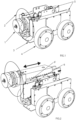
- Figure 1 shows an isometric view of the robotic device for the repair of large pipes where it resembled: the spray head (1), the screen (2), the frame (3), the wheels (4) and the unit control (5).
- FIG. 5 shows an embodiment in which the spray head operates within an angular sector exclusively; it can be seen that its perforations remain within the sector.
- the device comprises a frame (3) that houses the different elements that allow the projection of the resin, said frame houses at least one control system (5) and receives the two hoses: resin and catalyst, mixing in the robotic device itself in the mixing chamber (not shown); with 4 driving wheels (4). independently operated, from a cylindrical motorized spray head (1) which has a plurality of perforations through which the resin mixture is projected, behind the head it has a screen (2) that prevents splashes on the device, Figure 1 .
- the head can move linearly with respect to the frame using a conventional linear actuator (6), as well as be raised or tilted, figures 3 and 4 , this is possible by having an articulated system formed by three bars that join the body that contains the head.
- spraying and mixing chamber with the frame the ends of two of its bars (9 and 11) are articulated with a rotating torque to the body of the head / chamber while its opposite ends have a joint that allows rotation and has the possibility of linear translation when its rotation torques are installed on a thread and spindle mechanism activated by two motors (7 and 8) independently, it has a third bar (10) connected with a rotation torque to the frame and one of the previous bars at a point between their extremes.
- the position of the device is known by having a rotary encoder in at least one of its wheels whose signal is interpreted by a control unit (5); It comprises a hose collection system (not shown) synchronized to the forward/reverse of the device, an inertial measurement unit (IMU) to interpret the movement of the device, a vision system formed by a video camera and a power source. lighting, self-centering means of the spray head with respect to the pipe commanded by the control unit through the use of a laser sensor (LIDAR) to guarantee a homogeneous distribution of the projection in a layout that presents different sections, the position of the head is allowed through the articulated system described.
- a laser sensor LIDAR
- the rotary movement of the spray head and its perforations are limited to an angular portion defined by a stepper motor therein and a control unit.
Landscapes
- Engineering & Computer Science (AREA)
- General Engineering & Computer Science (AREA)
- Mechanical Engineering (AREA)
- Spray Control Apparatus (AREA)
- Coating Apparatus (AREA)
- Conveying And Assembling Of Building Elements In Situ (AREA)
Abstract
Description
- A hydraulic network is made up of pipes, accessories and structures that conduct the fluid from the collection point to the consumption/evacuation point. The purpose of the supply network is to provide water to users for domestic, public, commercial or industrial consumption in sufficient quantity, with the required sanitary quality and at an adequate service pressure. For its part, the sanitation network (urban drainage, sewage and purification) refers to the collection and transportation of wastewater, industrial and rainwater of a population from the place where it is generated to the place where it is discharged into the environment. natural or treated.
- Water infrastructures are aging, with the consequent risk of losing the current quality levels of supply and sanitation services. Currently they are repaired by inserting a mechanism manually pushed by rods into the pipe. This mechanism has a viewing and lighting camera for it and a valve for spraying epoxy resins that cover the inside of the pipe, creating a coating on it. The technical means available in this type of work have the following shortcomings or technological and functional limitations: the capacity of manual pushing with a rod is only about 45m per side of the cupping, the maximum resining time is about 50 minutes because above this time the resin cures inside the hose, forcing Stop the process, clean the hoses and resume resin coating. As the resin coating time progresses, the resin inside the hose becomes denser, which has a direct impact on the spraying of the resin, leading to a poorer quality of the layer. and greater roughness.
- A large number of solutions are based on the introduction of a malleable coating that is then inflated, as stated in the
patent document WO2016106448 , from the Canadian owner Un Flow Technologies 2000 Inc., others evolve this sleeve of repair using modern infusion techniques such asES277318T3 - There are no known devices that advantageously resolve the current limitations like the one recommended.
- Have a device that allows maintaining and repairing hydraulic networks without the need to carry out works, overcome the limitations of current manual push rod systems, reduce the number of cuppings and increase their distance; obtain a teleoperated and robotic device that can operate in networks of large sections. Mix resin and catalyst in the device itself and in real time, avoiding complications in the hoses, also increasing the times in which the equipment can work. Minimize the environmental impact of replacing pipes and associated civil works. Reduce execution time and economic investment.
- Have a motorized device that allows greater application distances to be achieved while minimizing network records.
- The repair of hydraulic networks without the need for works is carried out by projecting a layer of epoxy resin on the inside of the damaged surface with the aim of repairing all types of pathologies (clogging, corrosion, excessive pressure, poor construction, use and disuse or wear and tear over the years), for all types of materials (copper, iron, lead, PPR, PVC, cement, fiber cement) and for all types of hydraulic installations (hot or cold domestic water supply, heating and air conditioning systems , sanitation and stormwater systems, industrial processes including the food sector, liquid fuel conduction systems, tanks, irrigation systems).
- The recommended device is introduced inside the network. It has a frame that integrates at least four independently driven drive wheels, which provides it with a precise turning system as well as better traction and grip. The frame houses at least one control system and receives the two hoses, resin and catalyst, making the mixing in the robotic device itself in the mixing chamber (not shown) which has a valve for resin injection preventing the catalyst from acting on the resin transport hose. Mixing in this chamber avoids curing problems. in current state-of-the-art hoses, extending operating time.
- The projection of the resin/catalyst mixture is carried out by means of a spray head made up of a motorized rotating element in the shape of a cylinder which has a plurality of perforations connected to the mixing chamber, in this way the coating can be projected by pressure. in the fluid and the applied centrifugal force. A disc-shaped screen is placed behind the spray head in order to avoid splashes on the device. The head can move or retract in the direction of advance of the device by having a conventional linear actuator. This is useful for passing certain figures. (for example, elbows) that due to the normal length of the device would not allow us to turn. In this way it is possible to collect the linear actuator at the moment of passing the elbow without stopping resining.
- Singularly, the spray head must self-center when, for example, there is a change in section in the layout, but the device has means to vary its height as well as its inclination or advance with respect to the device, these last two degrees of freedom They are of great value in the projection of section changes, elbows or other figures of the network. These movements are possible by presenting an articulated system formed by three bars that join the body that contains the spray head and mixing chamber with the frame; it differs from a conventional mechanism known as scissors: in this invention the ends of two of its bars They are articulated with a rotary torque to the body of the head/camera described while their other ends, in addition to having a joint that allows rotation, have the possibility of moving linearly as their rotation torques are installed on a thread and spindle mechanism activated by two motors independently; It has a third bar connected with a rotation torque to the frame and to one of the previous bars at a point between its ends, thus allowing elevation and/or inclination. This tilting movement, the referred tilting movement, whether operated manually or automatically, allows the joints or other discontinuities of the pipes to be better covered compared to a constant perpendicular projection as occurs in other techniques of the state of the art. Detection of the pipe geometry can be carried out using optical distance measurement sensors such as those that use laser (LIDAR), or ultrasound; Versions have been planned in which the measurement comes from the interpretation of the images captured by your vision system.
- It has means to know the position of the device, where these means are formed by a rotary encoder on at least one of its wheels whose signal is interpreted by at least one control unit. Versions have been planned in which the device is located using a GPS or others in which the position is interpreted by measuring the hoses, comprising a hose collection system (not shown) synchronized to the forward/reverse of the device. This allows the hoses to always be at a certain tension.
- It has means to know the thickness of the resin layer by interpreting the values provided by the positioning means, advance speed and interpretation of the geometry of the pipe and the measurement of the flow rate, this interpretation is possible through its control unit.
- The stability of the assembly is reinforced by at least one inertial measurement unit (IMU).
- Sometimes it is convenient to project a coating in a specific area such as a deep crack or a detachment without having to excessively coat the nearby areas. For this purpose, versions have been provided in which the device has means to project the resin, limiting the rotary movement of the spray head and its perforations to an angular portion defined by a stepper motor therein and a control unit.
- It allows visualization of the pipeline using at least one vision system consisting of a video camera and a lighting source.
- For a better understanding of what is described herein, some drawings are attached in which, by way of example, a list of the figures of the proposed invention is represented.
Figure 1 shows an isometric view of the robotic device for the repair of large pipes where it resembled: the spray head (1), the screen (2), the frame (3), the wheels (4) and the unit control (5). - In the isometric view of
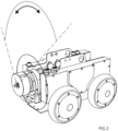
Figure 2 , the linear actuator (6) and the extended portion (6') of the actuator can be seen, the arrow indicates the forward/reverse movement of the spray head with respect to the chassis. - In
figures 3 and 4 you can see the lifting and tilting movements of the device with its bars (9, 10 and 11) and motors (7 and 8), as well as the rotation of the spray head, part of the equipment has been removed (control unit on one side) to facilitate the view of the referred elements. - The perspective view of
Figure 5 shows an embodiment in which the spray head operates within an angular sector exclusively; it can be seen that its perforations remain within the sector. - A preferred embodiment is cited as an example, the materials used in its manufacture being independent of the object of the invention, as well as the application methods and all accessory details that may be presented, as long as they do not affect its essentiality.
- This preferred mode of embodiment reflects the materialization and corporeality of the invention, specifying details that help understand the invention and how the technical requirements are resolved, in this way the device comprises a frame (3) that houses the different elements that allow the projection of the resin, said frame houses at least one control system (5) and receives the two hoses: resin and catalyst, mixing in the robotic device itself in the mixing chamber (not shown); with 4 driving wheels (4). independently operated, from a cylindrical motorized spray head (1) which has a plurality of perforations through which the resin mixture is projected, behind the head it has a screen (2) that prevents splashes on the device,
Figure 1 . The head can move linearly with respect to the frame using a conventional linear actuator (6), as well as be raised or tilted,figures 3 and 4 , this is possible by having an articulated system formed by three bars that join the body that contains the head. spraying and mixing chamber with the frame, the ends of two of its bars (9 and 11) are articulated with a rotating torque to the body of the head / chamber while its opposite ends have a joint that allows rotation and has the possibility of linear translation when its rotation torques are installed on a thread and spindle mechanism activated by two motors (7 and 8) independently, it has a third bar (10) connected with a rotation torque to the frame and one of the previous bars at a point between their extremes. - The position of the device is known by having a rotary encoder in at least one of its wheels whose signal is interpreted by a control unit (5); It comprises a hose collection system (not shown) synchronized to the forward/reverse of the device, an inertial measurement unit (IMU) to interpret the movement of the device, a vision system formed by a video camera and a power source. lighting, self-centering means of the spray head with respect to the pipe commanded by the control unit through the use of a laser sensor (LIDAR) to guarantee a homogeneous distribution of the projection in a layout that presents different sections, the position of the head is allowed through the articulated system described.
- It is provided in this embodiment that the rotary movement of the spray head and its perforations are limited to an angular portion defined by a stepper motor therein and a control unit.
Claims (5)
- Robotic device for the repair of large pipes that uses the projection of a mixture of resins for the maintenance of the networks characterized by a frame (3) that integrates at least four driving wheels (4) driven independently, of at least one mixing chamber for the resin and the catalyst, a spray head (1) made up of a cylinder-shaped motorized rotating element which has a plurality of perforations, a disc-shaped screen (2) located behind the spray head, means for advancing and retracting the spray head with respect to the device by means of at least one linear actuator (6), means for moving the spray head in height and inclination by means of an articulated system formed by three bars that join the body that contains the spray head and mixing chamber with the frame, the ends of two of its bars (9 and 11) are articulated with a rotating torque to the body of the head/chamber while its opposite ends have a joint that allows rotation and It has the possibility of linear translation as its rotation torques are installed on a screw and spindle mechanism activated by two motors (7 and 8) independently, it has a third bar (10) connected with a rotation torque to the frame and to one of the previous bars at a point between their ends; it comprises means for knowing the position of the device, where these means are formed by a rotary encoder on at least one of its wheels whose signal is interpreted by a control unit (5); It comprises a hose collection system synchronized with the advance/reverse of the device, an inertial measurement unit (IMU), a vision system formed by a video camera and a lighting source, means for self-centering of the spray head with respect to of the pipe commanded by the control unit through the use of a laser sensor (LIDAR).
- Robotic device for the repair of large pipes according to the first claim characterized by being the means to know the geometry of the pipe and interpret the images from your vision system.
- Robotic device for the repair of large pipes according to the previous claims characterized by presenting means to know the thickness of the resin layer by interpreting the values provided by the positioning means, advance speed, and interpretation of the geometry of the pipe and flow measurement, this interpretation is possible through its control unit.
- Robotic device for the repair of large pipes according to the previous claims characterized by presenting means for projecting in an angular sector by means of the actuation of a stepper motor of the spray head through its control unit and the limitation of the perforations of the head.
- Robotic device for the repair of large pipes according to the previous claims characterized by presenting means to know the position of the device through a global positioning system.
Applications Claiming Priority (2)
| Application Number | Priority Date | Filing Date | Title |
|---|---|---|---|
| ES202230612U ES1293889Y (en) | 2022-04-11 | 2022-04-11 | ROBOTIZED DEVICE FOR THE REPAIR OF LARGE DIMENSIONS PIPES |
| PCT/ES2023/070220 WO2023198947A1 (en) | 2022-04-11 | 2023-04-05 | Robotised device for repairing large pipes |
Publications (2)
| Publication Number | Publication Date |
|---|---|
| EP4509221A1 true EP4509221A1 (en) | 2025-02-19 |
| EP4509221A4 EP4509221A4 (en) | 2026-03-25 |
Family
ID=82850914
Family Applications (1)
| Application Number | Title | Priority Date | Filing Date |
|---|---|---|---|
| EP23787876.4A Pending EP4509221A4 (en) | 2022-04-11 | 2023-04-05 | ROBOTIZED DEVICE FOR REPAIRING LARGE PIPES |
Country Status (3)
| Country | Link |
|---|---|
| EP (1) | EP4509221A4 (en) |
| ES (1) | ES1293889Y (en) |
| WO (1) | WO2023198947A1 (en) |
Family Cites Families (11)
| Publication number | Priority date | Publication date | Assignee | Title |
|---|---|---|---|---|
| ES277318A1 (en) | 1962-05-14 | 1962-08-01 | Puertas Antonio | A convection heating system (Machine-translation by Google Translate, not legally binding) |
| US6966950B2 (en) * | 1998-03-25 | 2005-11-22 | Winiewicz Anthony E | Method and apparatus for treating underground pipeline |
| US9724872B2 (en) * | 2009-05-27 | 2017-08-08 | Lmk Technologies, Llc | Apparatus and method for lining a pipe |
| US20120172507A1 (en) * | 2009-10-22 | 2012-07-05 | Kent Weisenberg | Method and Apparatus for Lining Pipes with Isocyanate and Hydroxyl-Amine Resin Based on Castrol or Soy Oil |
| US8298613B2 (en) * | 2009-10-22 | 2012-10-30 | Quest Inspar LLC | Method of spray lining a pipe with an environmentally compatible impervious membrane |
| KR101324317B1 (en) * | 2011-10-20 | 2013-11-01 | 삼성중공업 주식회사 | method and apparatus for painting pipe |
| CA2972628C (en) | 2014-12-30 | 2023-03-07 | Nu Flow Technologies 2000 Inc. | Liner assembly for pipeline repair or reinforcement and method of installing same |
| CN108036150B (en) * | 2017-12-01 | 2019-10-01 | 山东金茂塑业有限公司 | A kind of drainpipe detecting robot |
| WO2020197919A1 (en) * | 2019-03-25 | 2020-10-01 | Sipp Techonologies, Llc | Internal pipe lining system having self-propelled, self-powered propulsion devices |
| US11731281B2 (en) * | 2020-07-02 | 2023-08-22 | Saudi Arabian Oil Company | Automation in a robotic pipe coating system |
| US11982632B2 (en) * | 2021-05-07 | 2024-05-14 | Saudi Arabian Oil Company | System and method for internal coating of offshore pipeline weld joints with fluorescent anti-corrosion coatings and wet inspection |
-
2022
- 2022-04-11 ES ES202230612U patent/ES1293889Y/en active Active
-
2023
- 2023-04-05 WO PCT/ES2023/070220 patent/WO2023198947A1/en not_active Ceased
- 2023-04-05 EP EP23787876.4A patent/EP4509221A4/en active Pending
Also Published As
| Publication number | Publication date |
|---|---|
| ES1293889Y (en) | 2022-11-15 |
| ES1293889U (en) | 2022-08-22 |
| EP4509221A4 (en) | 2026-03-25 |
| WO2023198947A1 (en) | 2023-10-19 |
Similar Documents
| Publication | Publication Date | Title |
|---|---|---|
| US7726256B1 (en) | Apparatus and method for lining large diameter pipe with an environmentally compatible impervious membrane | |
| US8468968B2 (en) | Method and apparatus for lining pipes with isocyanate and hydroxyl-amine resin based on castrol or soy oil | |
| KR101556503B1 (en) | Method and apparatus for lining pipes with environmentally compatible impervious membrane | |
| US5368423A (en) | Robotic cutter | |
| US6966950B2 (en) | Method and apparatus for treating underground pipeline | |
| US20120172507A1 (en) | Method and Apparatus for Lining Pipes with Isocyanate and Hydroxyl-Amine Resin Based on Castrol or Soy Oil | |
| JPH0353519B2 (en) | ||
| KR101222811B1 (en) | Winch for waterworks of waterpipe | |
| US6386797B1 (en) | Conduit liner cutter | |
| KR100358587B1 (en) | Apparatus for repairing waterworks and sewer by injecting chemical agent and method thereof | |
| KR101129163B1 (en) | Spray-lining apparatus for regenerating the superannuated water supply pipe | |
| US5253956A (en) | Method of lining branch line | |
| US8170715B1 (en) | Methods and devices for automated work in pipes based on impedance control | |
| US5385752A (en) | Method and apparatus for coating interior surfaces | |
| US6626616B2 (en) | Tapping tool for PVC pipes and fittings | |
| CA2747460A1 (en) | Method and apparatus for lining pipes with isocyanate and hydroxyl-amine resin based on castrol or soy oil | |
| WO2023198947A1 (en) | Robotised device for repairing large pipes | |
| US7128074B2 (en) | Scarifier for the interior surface of a pipeline | |
| KR100706581B1 (en) | Mortar pouring device | |
| AU754443B2 (en) | Spray cleaner for interior surface of pipeline | |
| US7066188B2 (en) | Interior sewer pipeline scarifying apparatus | |
| WO2013142394A1 (en) | Method and apparatus for lining pipes with isocyanate and hydroxyl-amine resin based castrol or soy oil | |
| AU2020277104A1 (en) | Remote Pipe Repair Apparatus and Method |
Legal Events
| Date | Code | Title | Description |
|---|---|---|---|
| STAA | Information on the status of an ep patent application or granted ep patent |
Free format text: STATUS: THE INTERNATIONAL PUBLICATION HAS BEEN MADE |
|
| PUAI | Public reference made under article 153(3) epc to a published international application that has entered the european phase |
Free format text: ORIGINAL CODE: 0009012 |
|
| STAA | Information on the status of an ep patent application or granted ep patent |
Free format text: STATUS: REQUEST FOR EXAMINATION WAS MADE |
|
| 17P | Request for examination filed |
Effective date: 20241111 |
|
| AK | Designated contracting states |
Kind code of ref document: A1 Designated state(s): AL AT BE BG CH CY CZ DE DK EE ES FI FR GB GR HR HU IE IS IT LI LT LU LV MC ME MK MT NL NO PL PT RO RS SE SI SK SM TR |
|
| DAV | Request for validation of the european patent (deleted) | ||
| DAX | Request for extension of the european patent (deleted) | ||
| A4 | Supplementary search report drawn up and despatched |
Effective date: 20260219 |
|
| RIC1 | Information provided on ipc code assigned before grant |
Ipc: B05B 13/06 20060101AFI20260213BHEP Ipc: F16L 55/1645 20060101ALI20260213BHEP Ipc: F16L 55/18 20060101ALI20260213BHEP Ipc: F16L 55/32 20060101ALI20260213BHEP Ipc: F16L 55/40 20060101ALI20260213BHEP Ipc: G01N 21/954 20060101ALI20260213BHEP Ipc: B05B 13/04 20060101ALI20260213BHEP Ipc: B05B 15/68 20180101ALI20260213BHEP Ipc: B05B 7/04 20060101ALI20260213BHEP Ipc: B05B 13/00 20060101ALI20260213BHEP |