EP4509090A1 - Removal tool and removal system - Google Patents
Removal tool and removal system Download PDFInfo
- Publication number
- EP4509090A1 EP4509090A1 EP23788087.7A EP23788087A EP4509090A1 EP 4509090 A1 EP4509090 A1 EP 4509090A1 EP 23788087 A EP23788087 A EP 23788087A EP 4509090 A1 EP4509090 A1 EP 4509090A1
- Authority
- EP
- European Patent Office
- Prior art keywords
- removal tool
- cylindrical body
- bottomed cylindrical
- hollow portion
- endoscopic treatment
- Prior art date
- Legal status (The legal status is an assumption and is not a legal conclusion. Google has not performed a legal analysis and makes no representation as to the accuracy of the status listed.)
- Pending
Links
Images








Classifications
-
- A—HUMAN NECESSITIES
- A61—MEDICAL OR VETERINARY SCIENCE; HYGIENE
- A61B—DIAGNOSIS; SURGERY; IDENTIFICATION
- A61B90/00—Instruments, implements or accessories specially adapted for surgery or diagnosis and not covered by any of the groups A61B1/00 - A61B50/00, e.g. for luxation treatment or for protecting wound edges
- A61B90/70—Cleaning devices specially adapted for surgical instruments
-
- A—HUMAN NECESSITIES
- A61—MEDICAL OR VETERINARY SCIENCE; HYGIENE
- A61B—DIAGNOSIS; SURGERY; IDENTIFICATION
- A61B1/00—Instruments for performing medical examinations of the interior of cavities or tubes of the body by visual or photographical inspection, e.g. endoscopes; Illuminating arrangements therefor
- A61B1/12—Instruments for performing medical examinations of the interior of cavities or tubes of the body by visual or photographical inspection, e.g. endoscopes; Illuminating arrangements therefor with cooling or rinsing arrangements
- A61B1/121—Instruments for performing medical examinations of the interior of cavities or tubes of the body by visual or photographical inspection, e.g. endoscopes; Illuminating arrangements therefor with cooling or rinsing arrangements provided with means for cleaning post-use
- A61B1/122—Instruments for performing medical examinations of the interior of cavities or tubes of the body by visual or photographical inspection, e.g. endoscopes; Illuminating arrangements therefor with cooling or rinsing arrangements provided with means for cleaning post-use using cleaning tools, e.g. brushes
-
- A—HUMAN NECESSITIES
- A61—MEDICAL OR VETERINARY SCIENCE; HYGIENE
- A61B—DIAGNOSIS; SURGERY; IDENTIFICATION
- A61B18/00—Surgical instruments, devices or methods for transferring non-mechanical forms of energy to or from the body
- A61B18/04—Surgical instruments, devices or methods for transferring non-mechanical forms of energy to or from the body by heating
- A61B18/12—Surgical instruments, devices or methods for transferring non-mechanical forms of energy to or from the body by heating by passing a current through the tissue to be heated, e.g. high-frequency current
- A61B18/14—Probes or electrodes therefor
- A61B18/1482—Probes or electrodes therefor having a long rigid shaft for accessing the inner body transcutaneously in minimal invasive surgery, e.g. laparoscopy
-
- B—PERFORMING OPERATIONS; TRANSPORTING
- B08—CLEANING
- B08B—CLEANING IN GENERAL; PREVENTION OF FOULING IN GENERAL
- B08B9/00—Cleaning hollow articles by methods or apparatus specially adapted thereto
- B08B9/02—Cleaning pipes or tubes or systems of pipes or tubes
- B08B9/027—Cleaning the internal surfaces; Removal of blockages
- B08B9/04—Cleaning the internal surfaces; Removal of blockages using cleaning devices introduced into and moved along the pipes
- B08B9/043—Cleaning the internal surfaces; Removal of blockages using cleaning devices introduced into and moved along the pipes moved by externally powered mechanical linkage, e.g. pushed or drawn through the pipes
- B08B9/0436—Cleaning the internal surfaces; Removal of blockages using cleaning devices introduced into and moved along the pipes moved by externally powered mechanical linkage, e.g. pushed or drawn through the pipes provided with mechanical cleaning tools, e.g. scrapers, with or without additional fluid jets
-
- A—HUMAN NECESSITIES
- A61—MEDICAL OR VETERINARY SCIENCE; HYGIENE
- A61B—DIAGNOSIS; SURGERY; IDENTIFICATION
- A61B18/00—Surgical instruments, devices or methods for transferring non-mechanical forms of energy to or from the body
- A61B2018/00571—Surgical instruments, devices or methods for transferring non-mechanical forms of energy to or from the body for achieving a particular surgical effect
- A61B2018/00595—Cauterization
-
- A—HUMAN NECESSITIES
- A61—MEDICAL OR VETERINARY SCIENCE; HYGIENE
- A61B—DIAGNOSIS; SURGERY; IDENTIFICATION
- A61B90/00—Instruments, implements or accessories specially adapted for surgery or diagnosis and not covered by any of the groups A61B1/00 - A61B50/00, e.g. for luxation treatment or for protecting wound edges
- A61B90/70—Cleaning devices specially adapted for surgical instruments
- A61B2090/701—Cleaning devices specially adapted for surgical instruments for flexible tubular instruments, e.g. endoscopes
-
- A—HUMAN NECESSITIES
- A61—MEDICAL OR VETERINARY SCIENCE; HYGIENE
- A61M—DEVICES FOR INTRODUCING MEDIA INTO, OR ONTO, THE BODY; DEVICES FOR TRANSDUCING BODY MEDIA OR FOR TAKING MEDIA FROM THE BODY; DEVICES FOR PRODUCING OR ENDING SLEEP OR STUPOR
- A61M25/00—Catheters; Hollow probes
- A61M2025/0019—Cleaning catheters or the like, e.g. for reuse of the device, for avoiding replacement
-
- B—PERFORMING OPERATIONS; TRANSPORTING
- B08—CLEANING
- B08B—CLEANING IN GENERAL; PREVENTION OF FOULING IN GENERAL
- B08B2209/00—Details of machines or methods for cleaning hollow articles
- B08B2209/02—Details of apparatuses or methods for cleaning pipes or tubes
- B08B2209/027—Details of apparatuses or methods for cleaning pipes or tubes for cleaning the internal surfaces
- B08B2209/04—Details of apparatuses or methods for cleaning pipes or tubes for cleaning the internal surfaces using cleaning devices introduced into and moved along the pipes
Definitions
- the present invention relates to a removal tool and a removal system.
- an endoscopic treatment tool provided with a high frequency knife for excising a mucous membrane or the like by energizing a high frequency current is used.
- thermally coagulated by cauterization with the high frequency knife may adhere to an inside of a channel of the endoscopic treatment tool.
- the channel is clogged by the adhering substance.
- a worker therefore, removes the adhering substance from the inside of the channel using, for example, a removal tool (see, e.g., Patent Literature 1).
- Patent Literature 1 US 2020/0323610 A
- the worker manually sets the removal tool in the channel of the precise and small endoscopic treatment tool to remove the adhering substance adhered to the inside of the channel.
- the removal tool therefore, is required to have high operability.
- the present invention has been made in view of the above circumstances, and an object of the present invention is to provide a removal tool and a removal system having high operability.
- a removal tool for removing an adhering substance adhered to an inside of a channel of an endoscopic treatment tool, and the removal tool includes: a bottomed cylindrical body having an opening at one end; and an elongated part formed in a hollow portion of the bottomed cylindrical body so as to extend from a bottom of the hollow portion toward an opening side of the hollow portion, which is capable of inserting into the channel.
- the hollow portion of the bottomed cylindrical body expands from the bottom side toward the opening.
- a plurality of slits dividing a side surface of the bottomed cylindrical body into a plurality of portions may be formed in a circumferential direction around an axis of the bottomed cylindrical body.
- the removal tool according to an embodiment of the present invention may further includes an exterior part holding the bottomed cylindrical body.
- the bottomed cylindrical body has higher pliability than the exterior part.
- the hollow portion of the bottomed cylindrical body may include a tapered portion expanding continuously or stepwise from the bottom side toward the opening.
- the bottomed cylindrical body includes a constricted portion formed, for example, in a cylindrical shape and having an outer diameter narrower at a central portion than at end portions in an axial direction of the bottomed cylindrical body.
- the bottomed cylindrical body is formed of a material through which light having at least a part of visible wavelength is capable of passing.
- an edge portion may be formed on a side surface of the elongated part.
- a distal end portion of the elongated part has, for example, a tapered shape.
- the hollow portion of the bottomed cylindrical body may have a circular cross section orthogonal to an axial direction of the bottomed cylindrical body, and the elongated part may be disposed in the hollow portion so as to pass through a center of the circular cross section and extend along the axial direction.
- the hollow portion of the bottomed cylindrical body may have a circular cross section orthogonal to an axial direction of the bottomed cylindrical body, and the elongated part may be disposed in the hollow portion so as to pass through a position deviated from a center of the circular cross section and extend along the axial direction.
- a removal system includes: any one of the removal tools described above; and an endoscopic treatment tool to be inserted into the removal tool.
- an indicator indicating an amount of the endoscopic treatment tool to be inserted into the removal tool is marked on the endoscopic treatment tool.
- a removal tool for removing an adhering substance adhered to an inside of a channel of an endoscopic treatment tool, and the removal tool includes: a bottomed cylindrical body having an opening at one end; and an elongated part formed in a hollow portion of the bottomed cylindrical body so as to extend from a bottom of the hollow portion toward an opening side of the hollow portion, which is capable of inserting into the channel.
- the hollow portion of the bottomed cylindrical body has a circular cross section orthogonal to an axial direction of the bottomed cylindrical body, and the elongated part is disposed in the hollow portion so as to pass through a position deviated from a center of the circular cross section and extend along the axial direction.
- the removal tool and the removal system having high operability are provided.
- the removal tool removes an adhering substance adhered to an inside of a channel of an endoscopic treatment tool.
- the removal system includes the removal tool and the endoscopic treatment tool.
- a work of removing the adhering substance using the removal tool is performed by, for example, an operator (doctor) or another medical worker (physician assistant, nurse, etc.).
- a person who performs the work of removing the adhering substance using the removal tool is collectively referred to as a worker.
- Fig. 1 is a perspective view of a removal tool 1 according to a first embodiment of the present invention.
- Fig. 2 is an arrow view of the removal tool 1 as viewed from a direction of an arrow A in Fig. 1 .
- Fig. 3 is a cross-sectional view of the removal tool 1.
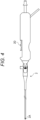
- Fig. 4 is an overall view of an endoscopic treatment tool 2 inserted into the removal tool 1.
- Fig. 5 is a view illustrating an internal structure of a distal end portion 2A of the endoscopic treatment tool 2.
- Fig. 6 is a view illustrating a state in which the endoscopic treatment tool 2 is inserted into the removal tool 1.
- Fig. 7 is a view illustrating a state in which an adhering substance B (hemoglobin, protein, etc., which is thermally coagulated by cauterization) adhered to an inside of a channel 2B of the endoscopic treatment tool 2 is removed.
- an adhering substance B hemoglobin, protein, etc., which is
- the removal tool 1 includes a housing 10, a rod part 20, and a base 30.
- the housing 10 is a bottomed cylindrical body having an opening at one end, and a hollow portion 12 is formed in the housing 10.
- the distal end portion 2A of the endoscopic treatment tool 2 is inserted into the hollow portion 12 through an opening 12A of the hollow portion 12 by a worker.
- the housing 10 is, for example, a molded resin product, and is formed of, for example, acrylonitrile butadiene styrene (ABS) copolymer or polycarbonate.
- the housing 10 may be formed of a material through which light having at least a part of visible wavelength is capable of passing, which is, for example, a transparent medium or a translucent medium, so that the worker can view the rod part 20 provided in the hollow portion 12 and the distal end portion 2A of the endoscopic treatment tool 2 inserted in the hollow portion 12.
- a transparent material referred to as a "transparent material”.
- the housing 10 is formed in a cylindrical shape.
- An axis which is a line on a central axis of the housing 10 is denoted by a reference sign AX.
- an axis AX direction of the housing 10 is defined as a Z direction, and two directions orthogonal to the Z direction and orthogonal to each other are defined as an X direction and a Y direction.
- the X direction, the Y direction, and the Z direction orthogonal to each other form a left-handed system.
- the housing 10 has a cylindrical appearance with a constricted center in a longitudinal direction. Specifically, the housing 10 has an outer shape including a constricted portion 14 having an outer diameter narrower at a central portion than at end portions in the axis AX direction. Since the housing 10 has the outer shape including the constricted portion 14, the worker can easily hold the housing 10 (in other words, the removal tool 1).
- the hollow portion 12 of the housing 10 has a shape in which an orthogonal cross section (specifically, an XY cross section) orthogonal to the axis AX direction is circular.
- the rod part 20 is disposed in the hollow portion 12 having a circular XY cross section.
- the rod part 20 is an example of an elongated part to be inserted into the channel 2B of the endoscopic treatment tool 2.
- the rod part 20 is formed to extend from a bottom 12B of the hollow portion 12 toward the opening 12A side of the hollow portion 12.
- the rod part 20 is an elongated cylindrical metal component, and is formed of, for example, SUS304.
- a root of the rod part 20 is embedded in the base 30.
- the rod part 20 and the base 30 are inserted into a through hole 10B formed in a proximal end portion 10A of the housing 10 and fixed with an adhesive or the like.
- the rod part 20 penetrates the through hole 10B and is arranged to extend coaxially with the axis AX in the hollow portion 12 (in other words, it passes through the center of the circular cross section of the hollow portion 12 and along the axis AX direction).
- a portion extending coaxially with the axis AX in the hollow portion 12 is longer than the entire length of the channel 2B of the endoscopic treatment tool 2.
- An outer diameter of the rod part 20 is smaller than an inner diameter of the channel 2B of the endoscopic treatment tool 2. The worker, therefore, can insert the rod part 20 into the channel 2B.
- the endoscopic treatment tool 2 is, for example, a treatment tool used for ESD, and includes a high frequency knife 2C at the distal end portion 2A thereof.
- the amount of protrusion of the high frequency knife 2C with respect to a distal end surface 2Aa of the distal end portion 2A changes depending on a manipulation of an operation unit 2D.
- the operator manipulates the operation unit 2D depending on a procedure details (marking, local injection, incision, exfoliation, and hemostasis, etc.) and causes the high frequency knife 2C to protrude from the distal end surface 2Aa by an appropriate amount.
- the channel 2B that is a through line is formed.
- the channel 2B is disposed coaxially with the distal end portion 2A having a tubular shape.
- the channel 2B communicates with a flow path 2E at a subsequent stage.
- a water supply pump or a suction pump is connected to a proximal end of the flow path 2E.
- liquid cleaning liquid, chemical solution, etc.
- the liquid supplied into the flow path 2E is injected from the distal end of the high frequency knife 2C to an outside via the flow path 2E and the channel 2B.
- a liquid medicine into a submucosal layer or to remove an adhering substance (blood or mucus) adhered to a body cavity.
- the suction pump When the suction pump is connected to the proximal end of the flow path 2E, for example, the adhering substance adhered to the body cavity is sucked into the channel 2B.
- the adhering substance sucked into the channel 2B is put into a container or the like included in the suction pump via the flow path 2E.
- Hemoglobin, protein, and the like thermally coagulated by cauterization using the high frequency knife 2C may adhere to the channel 2B having such a function.
- the channel 2B having such a function.
- the inner diameter of the channel 2B is extremely thin, for example, around 0.2 mm to 0.4 mm. The channel 2B, therefore, is easily clogged with the adhering substances. When the channel 2B is clogged, it becomes difficult to pump liquid or gas into the channel 2B, and it becomes more difficult to remove the adhering substances.
- the worker therefore, removes the adhering substance in the channel 2B using the removal tool 1.
- a removal work of the adhering substance using the removal tool 1 will be specifically described.
- the worker removes the adhering substance in the channel 2B using the removal tool 1 during or after a procedure by the operator. For example, during the procedure, the worker removes the endoscopic treatment tool 2 from an endoscope, and inserts the distal end portion 2A of the endoscopic treatment tool 2 into the hollow portion 12 through the opening 12A of the hollow portion 12 formed in the housing 10.
- slits 16 that divide a side surface 10C of the housing 10 into a plurality of portions are formed in a circumferential direction around the axis AX (here, in a circumferential direction of the housing 10 formed in the cylindrical shape).
- the slit 16 is formed to extend in the axis AX direction from a distal end portion 10E of the housing 10 toward the proximal end portion 10A to a middle position of the side surface 10C.
- the four slits 16 are formed on the side surface 10C of the housing 10 at intervals of 90 degrees in the circumferential direction of the housing 10.
- the side surface 10C is divided into four portions in the circumferential direction of the housing 10 at portions where the slits 16 are formed.
- the hollow portion 12 includes a tapered portion 12C and a non-tapered portion 12D.
- the tapered portion 12C is formed to extend in the axis AX direction from the opening 12A to an intermediate position C of the hollow portion 12.
- the non-tapered portion 12D is formed to extend in the axis AX direction from the intermediate position C, which is the proximal end of the tapered portion 12C, to the bottom 12B.
- the tapered portion 12C expands from the bottom 12B side toward the opening 12A. That is, the tapered portion 12C is formed such that the XY cross section orthogonal to the axis AX direction becomes larger from the bottom 12B side toward the opening 12A.
- the tapered portion 12C has the XY cross section becoming larger continuously from the bottom 12B side toward the opening 12A.
- the tapered portion 12C may have an XY cross section becoming larger stepwise from the bottom 12B side toward the opening 12A.
- the hollow portion 12 has a shape in which the XY cross section is circular. Therefore, “expansion” may also be read as “diameter expansion”. That is, the tapered portion 12C is formed such that an inner diameter increases continuously or stepwise from the bottom 12B side toward the opening 12A.
- the largest XY cross section of the tapered portion 12C (in other words, an inner diameter) is larger than the XY cross section of the distal end portion 2A of the endoscopic treatment tool 2 (in other words, an outer diameter). The worker, therefore, can easily insert the distal end portion 2A into the hollow portion 12 (more precisely, the tapered portion 12C).
- the inner diameter of the tapered portion 12C decreases as approaching the non-tapered portion 12D, and becomes smaller than the outer diameter of the distal end portion 2A of the endoscopic treatment tool 2, for example, at a position just before the intermediate position C (the position on the negative side in the Z direction with respect to the intermediate position C).
- the tapered portion 12C has the smallest inner diameter at the intermediate position C which is the proximal end.
- the inner diameter of the non-tapered portion 12D is the same as the inner diameter at the intermediate position C over the entire length. That is, the inner diameter of the non-tapered portion 12D is smaller than the outer diameter of the distal end portion 2A of the endoscopic treatment tool 2 over the entire length thereof.
- the tapered portion 12C further expands in diameter from the bottom 12B side toward the opening 12A, and the non-tapered portion 12D formed as to have a constant inner diameter expands in diameter from the bottom 12B side toward the opening 12A.
- a degree of diameter expansion due to elastic deformation of the portion 10D changes depending on the outer diameter of the distal end portion 2A of the endoscopic treatment tool 2 inserted into the hollow portion 12.
- the outer diameter of the distal end portion 2A is slightly larger than the inner diameter of the non-tapered portion 12D.
- the degree of diameter expansion due to the elastic deformation of the portion 10D is extremely small. Accordingly, the inner diameter of the non-tapered portion 12D is illustrated constant in Figs. 6 and 7 for convenience.
- the worker can insert the distal end portion 2A to a point beyond the intermediate position C (i.e., up to the non-tapered portion 12D).
- the distal end portion 2A inserted to the non-tapered portion 12D is slidably held in the Z direction at a position coaxial with the axis AX by an external force applied from the entire circumferential direction (specifically, the reaction force from the elastically deformed portion 10D) (see, for example, Fig. 6 ).
- the channel 2B of the distal end portion 2A held at a position coaxial with the axis AX is located on the same straight line as the rod part 20 similarly extending coaxially with the axis AX.
- the worker therefore, can easily insert the rod part 20 into the channel 2B. That is, the removal tool 1 configured as described above has high operability.
- the housing 10 is formed of a transparent material, the worker can visually grasp the positional relationship between the rod part 20 and the channel 2B. Also from this point, the worker can easily insert the rod part 20 into the channel 2B.
- the distal end portion 20A of the rod part 20 has a tapered shape so that the worker can easily insert the rod part 20 into the channel 2B. As illustrated in Fig. 6 , the distal end portion 20A has a R chamfered shape. In another embodiment, the distal end portion 20A may be C chamfered or tapered.
- An indicator 2F is marked on an outer peripheral surface of the endoscopic treatment tool 2.
- the indicator 2F indicates an insertion amount of the distal end portion 2A to be inserted into the removal tool 1. As illustrated in Fig. 7 , the worker inserts the distal end portion 2A into the hollow portion 12 until the indicator 2F reaches the opening 12A. As a result, the rod part 20 penetrates the channel 2B.
- the adhering substance adhered to the inside of the channel 2B is crushed and pushed out to the flow path 2E. Residues remaining in the channel 2B and the flow path 2E after crushing can be discharged from the channel 2B to the outside by pumping liquid or gas using the water pump or the suction pump.
- the distal end portion 2A of the endoscopic treatment tool 2 inserted into the hollow portion 12 is held coaxially with the rod part 20. The worker, therefore, can easily insert the rod part 20 into the channel 2B.
- the inner diameter of the hollow portion 12 changes in accordance with the outer diameter of the distal end portion 2A.
- the worker therefore, can use the removal tool 1 for a plurality of types of the endoscopic treatment tools 2 having different outer diameters of the distal end portions 2A.
- Fig. 8 is a perspective view of a removal tool 201 according to a second embodiment of the present invention.
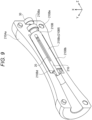
- Fig. 9 is a perspective view illustrating an internal structure of the removal tool 201.
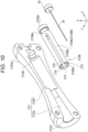
- Fig. 10 is an exploded perspective view illustrating the internal structure of the removal tool 201.
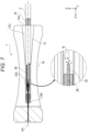
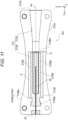
- Fig. 11 is a cross-sectional view illustrating the internal structure of the removal tool 201.
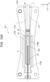
- Figs. 12A and 12B are views illustrating states in which the endoscopic treatment tool 2 is inserted into the removal tool 201.
- the removal tool 201 includes the rod part 20, the base 30, and a housing 210.
- the housing 210 includes an exterior part 210A and an inner cylinder part 210B.
- the exterior part 210A is, for example, a resin molded product, is a bottomed cylindrical body having an opening at one end, and has a cylindrical appearance (i.e., an outer shape including a constricted portion 214) with a constricted center in a longitudinal direction, similarly to the housing 10 of the first embodiment.
- the exterior part 210A includes a pair of halved portions 210Aa and 210Ab.
- the halved portions 210Aa and 210Ab have a shape obtained by vertically dividing a cylindrical shape in which a center in the longitudinal direction is constricted as described above by a plane including the axis AX direction.
- the cylindrical exterior part 210A is formed.
- An illustration of the halved portion 210Ab is omitted In Figs. 9 and 10 .
- a hollow portion 212 formed in the exterior part 210A includes a guide portion 212a and an accommodating portion 212b.
- the guide portion 212a is formed to extend in the axis AX direction from an opening 212A of the hollow portion 212 to an intermediate position D of the hollow portion 212.
- the accommodating portion 212b is formed to extend in the axis AX direction from the intermediate position D, which is a proximal end of the guide portion 212a, to a bottom 212B.
- An inner diameter of the guide portion 212a is larger than the outer diameter of the distal end portion 2A of the endoscopic treatment tool 2 over the entire length thereof.
- the guide portion 212a has a shape expanded in diameter toward the opening 212A. The worker, therefore, can easily insert the distal end portion 2A into the guide portion 212a through the opening 212A (see, for example, Fig. 12A ).
- the inner cylinder part 210B is accommodated in the accommodating portion 212b.
- the inner cylinder part 210B is, for example, a resin molded product including a proximal end portion 210Ba and a tubular portion 210Bb.
- the proximal end portion 210Ba is fixed to the accommodating portion 212b with an adhesive or the like.
- the inner cylinder part 210B is disposed coaxially with the exterior part 210A (i.e., at a position centered on the axis AX) in the accommodating portion 212b.
- the tubular portion 210Bb is a bottomed cylindrical body having an opening at one end, and is formed in a cylindrical shape.
- slits 216 that divide a side surface 210Bc of the tubular portion 210Bb into a plurality of portions in the direction around the axis AX (here, in a circumferential direction of the tubular portion 210Bb formed in a cylindrical shape,) are formed.
- the slits 216 are formed to extend in the axis AX direction from the distal end portion 210Bd of the tubular portion 210Bb toward the proximal end portion 210Be to an intermediate position of the side surface 210Bc.
- four slits 216 are formed on the side surface 210Bc of the tubular portion 210Bb at intervals of 90 degrees in the circumferential direction of the tubular portion 210Bb.
- the side surface 210Bc is divided into four portions in the circumferential direction of the tubular portion 210Bb at the portions where the slits 216 are formed.
- An inner diameter of the tubular portion 210Bb is smaller than the outer diameter of the distal end portion 2A of the endoscopic treatment tool 2 over the entire length thereof.
- the worker can insert the distal end portion 2A of the endoscopic treatment tool 2 into the tubular portion 210Bb.
- the distal end portion 2A inserted into the tubular portion 210Bb is slidably held in the Z direction at a position coaxial with the axis AX by external forces applied from the entire circumferential direction (specifically, reaction forces from the elastically deformed portions 210Bf) (see, for example, Fig. 12B ).
- the channel 2B of the distal end portion 2A held at a position coaxial with the axis AX is located on the same straight line as the rod part 20 also extending coaxially with the axis AX.
- the worker therefore, can easily insert the rod part 20 into the channel 2B, crush the adhering substance adhered to the inside of the channel 2B, and push out the adhering substance to the flow path 2E of the endoscopic treatment tool 2. That is, the removal tool 201 configured as described above also has high operability.
- the distal end portion 2A of the endoscopic treatment tool 2 inserted into the hollow portion 212 is held coaxially with the rod part 20 also in the second embodiment. The worker, therefore, can easily insert the rod part 20 into the channel 2B.
- the inner diameter of the hollow portion 212 changes in accordance with the outer diameter of the distal end portion 2A due to the elastic deformation of the side surface 210Bc (more specifically, the portions 210Bf) also in the second embodiment.
- the worker therefore, can use the removal tool 201 for a plurality of types of the endoscopic treatment tools 2 having different outer diameters of the distal end portions 2A.
- the distal end portion 20A of the rod part 20 has a tapered shape so that the worker can easily insert the rod part 20 into the channel 2B also in the second embodiment.
- the worker can visually grasp the positional relationship between the rod part 20 and the channel 2B. Also from this point, the worker can easily insert the rod part 20 into the channel 2B.
- the inner cylinder part 210B which is an example of the bottomed cylindrical body, has higher pliability than the exterior part 210A. The worker, therefore, can insert the distal end portion 2A into the inner cylinder part 210B with a light load. In addition, since the exterior part 210A itself gripped by the worker is not elastically deformed, the worker can easily handle the removal tool 201.
- the exterior part 210A and the inner cylinder part 210B are formed of, for example, the same material.
- the inner cylinder part 210B is formed to be thinner than the exterior part 210A, and thus has higher pliability than the exterior part 210A.
- the exterior part 210A and the inner cylinder part 210B may be formed of different materials.
- the inner cylinder part 210B is formed of a material having a lower elastic modulus than the exterior part 210A.
- Fig. 13 is a perspective view of a removal tool 301 according to a third embodiment of the present invention.
- Fig. 14 is a cross-sectional view illustrating an internal structure of the removal tool 301.
- Figs. 15A and 15B are views illustrating a state in which the endoscopic treatment tool 2 is inserted into the removal tool 301.
- the removal tool 301 includes the rod part 20, the base 30, and a housing 310.
- the housing 310 is, for example, a resin molded product, is a bottomed cylindrical body having an opening at one end, and has a cylindrical appearance (i.e., an outer shape including a constricted portion 314) with a constricted center in a longitudinal direction, similarly to the housing 10 of the first embodiment.
- the housing 310 is different from the housing 10 of the first embodiment in which no slit is formed. Instead, a tapered portion 312C is formed in a hollow portion 312 of the housing 310.
- the tapered portion 312C ranges over an entire portion from a bottom 312B of the hollow portion 312 to an opening 312A.
- the tapered portion 312C has a truncated cone shape expanding in diameter from the bottom 312B side toward the opening 312A. That is, the tapered portion 312C has the largest inner diameter at a position on the most negative side in the Z direction and the smallest inner diameter at a position on the most positive side in the Z direction.
- the inner diameter of the tapered portion 312C increases continuously from the bottom 312B side toward the opening 312A.
- a configuration in which the inner diameter of the tapered portion 312C increases stepwise from the bottom 312B side toward the opening 312A is also included in a scope of the present invention.
- a maximum inner diameter of the tapered portion 312C is denoted by a reference numeral D1
- a minimum inner diameter of the tapered portion 312C is denoted by a reference numeral D2.
- the distal end portion 2A having an outer diameter D3 is inserted into the tapered portion 312C.
- the outer diameter D3 is smaller than the inner diameter D1 of the tapered portion 312C and larger than the inner diameter D2 of the tapered portion 312C.
- the worker can insert the distal end portion 2A of the endoscopic treatment tool 2 into the tapered portion 312C.
- the worker can insert the rod part 20 into the channel 2B by further inserting the distal end portion 2A.
- the tapered portion 312C has the same inner diameter as the outer diameter D3 at an intermediate position D3'. Therefore, the entire peripheral edge portion of the distal end portion 2A of the endoscopic treatment tool 2 is pressed against an inner peripheral surface of the tapered portion 312C at the intermediate position D3'.
- the rod part 20 penetrates the channel 2B. As a result, the adhering substance adhered to the inside of the channel 2B is crushed and pushed out to the flow path 2E of the endoscopic treatment tool 2.
- the removal tool 301 When the distal end portion 2A of the endoscopic treatment tool 2 is pressed against the inner peripheral surface of the tapered portion 312C and stopped, the worker can grasp that the rod part 20 has penetrated the channel 2B (in other words, the adhering substance is crushed and pushed out to the flow path 2E of the endoscopic treatment tool 2). In addition, the worker can remove the adhering substance in the channel 2B without inserting the distal end portion 2A to the deepest portion of the tapered portion 312C (here, by simply inserting the distal end portion 2A to the intermediate position D3'). As described above, the removal tool 301 according to the third embodiment also has high operability.
- the distal end portion 2A having an outer diameter D4 is inserted into the tapered portion 312C.
- the outer diameter D4 is smaller than the inner diameter D2 of the tapered portion 312C. The worker, therefore, can insert the distal end portion 2A to the bottom 312B which is the deepest portion of the tapered portion 312C.
- the rod part 20 penetrates the channel 2B.
- the adhering substance adhered to the inside of the channel 2B is crushed and pushed out to the flow path 2E of the endoscopic treatment tool 2.
- the worker can grasp that the rod part 20 has penetrated the channel 2B (in other words, the adhering substance is crushed and pushed out to the flow path 2E of the endoscopic treatment tool 2).
- the removal tool 301 can be used for a plurality of types of endoscopic treatment tools 2 in which the outer diameters of the distal end portions 2A are smaller than the inner diameter D1.
- the entire peripheral edge portion of the distal end portion 2A is pressed against the inner peripheral surface of the tapered portion 312C at an intermediate position in the tapered portion 312C.
- the distal end portion 2A cannot move in the tapered portion 312C unless the worker moves the distal end portion 2A to the negative side in the Z direction.
- the housing 310 is formed of a transparent material. The worker, therefore, can visually grasp the positional relationship between the rod part 20 and the channel 2B. Also from this point, the worker can easily insert the rod part 20 into the channel 2B.
- the distal end portion 20A of the rod part 20 has a tapered shape so that the worker can easily insert the rod part 20 into the channel 2B also in the third embodiment.
- Fig. 16 is a cross-sectional view illustrating an internal structure of a removal tool 401 according to a fourth embodiment of the present invention.
- Fig. 17 is a cross-sectional view taken from line F-F in Fig. 16 .
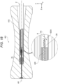
- Fig. 18 is a view illustrating a state in which the endoscopic treatment tool 2 is inserted into the removal tool 401.
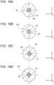
- Figs. 19A to 19D are cross-sectional views illustrating a state in which the endoscopic treatment tool 2 is inserted into the removal tool 401.
- the removal tool 401 includes a housing 410, a rod part 420, and a base 430.
- the housing 410 is, for example, a resin molded product, is a bottomed cylindrical body having an opening at one end, and has a cylindrical appearance with a constricted center in a longitudinal direction (i.e., an outer shape including a constricted portion 414), similarly to the housing 10 of the first embodiment.
- the housing 410 is the same as the housing 10 of the first embodiment except that the slits 16 are not formed.
- the base 430 has a cylindrical shape.
- a root of the rod part 420 is embedded at a position shifted from a center of the base 430 (eccentric position).
- the rod part 420 and the base 430 are inserted into a through hole 410B formed in a proximal end portion 410A of the housing 410 and fixed with an adhesive or the like.
- the rod part 420 penetrates the through hole 410B and is arranged to extend at a position eccentric to the axis AX in a hollow portion 412 of the housing 410 (in other words, it passes through a position deviated from a center of a circular cross section of the hollow portion 412 and extends along the axis AX direction).
- the outer diameter of the distal end portion 2A of the endoscopic treatment tool 2 and an inner diameter of a non-tapered portion 412D of the hollow portion 412 are substantially the same. Therefore, when the distal end portion 2A is inserted into the non-tapered portion 412D, the distal end portion 2A is positioned coaxially with the axis AX which is a central axis of the non-tapered portion 412D.
- the rod part 420 is located eccentrically from the axis AX.
- An outer diameter of the rod part 420 is smaller than the inner diameter of the channel 2B.
- the rod part 420 moves at the position eccentric to the axis AX in the channel 2B so as to rub the inner peripheral surface of the channel 2B.
- the adhering substance adhered to the inside of the channel 2B is scraped off by the rod part 420 and crushed. Therefore, the adhering substance can be reliably removed from the inside of the channel 2B.
- An edge portion may be formed on a side surface of the rod part 420.
- Fig. 20A illustrates an XY cross section of a rod part 420 according to a first modification.
- the rod part 420 is formed to have a hexagonal XY cross section, and has a shape including a total of six edge portions on the side surface.
- Fig. 20B illustrates an XY cross section of a rod part 420 according to a second modification.
- the rod part 420 is formed to have a triangular XY cross section, and has a shape including a total of three edge portions on the side surface.
- a distal end portion 420A of the rod part 420 has a tapered shape so that the worker can easily insert the rod part 420 into the channel 2B also in the fourth embodiment.
- the housing 410 is formed of a transparent material. The worker, therefore, can visually grasp the positional relationship between the rod part 420 and the channel 2B. As a result, the worker can easily insert the rod part 420 into the channel 2B.
Landscapes
- Health & Medical Sciences (AREA)
- Life Sciences & Earth Sciences (AREA)
- Surgery (AREA)
- Engineering & Computer Science (AREA)
- Veterinary Medicine (AREA)
- Public Health (AREA)
- General Health & Medical Sciences (AREA)
- Animal Behavior & Ethology (AREA)
- Nuclear Medicine, Radiotherapy & Molecular Imaging (AREA)
- Molecular Biology (AREA)
- Biomedical Technology (AREA)
- Heart & Thoracic Surgery (AREA)
- Medical Informatics (AREA)
- Pathology (AREA)
- Oral & Maxillofacial Surgery (AREA)
- Physics & Mathematics (AREA)
- Mechanical Engineering (AREA)
- Radiology & Medical Imaging (AREA)
- Optics & Photonics (AREA)
- Biophysics (AREA)
- Plasma & Fusion (AREA)
- Otolaryngology (AREA)
- Endoscopes (AREA)
- Surgical Instruments (AREA)
Abstract
Description
- The present invention relates to a removal tool and a removal system.
- In an endoscopic submucosal dissection (ESD), an endoscopic treatment tool provided with a high frequency knife for excising a mucous membrane or the like by energizing a high frequency current is used.
- In this type of endoscopic treatment tool, for example, hemoglobin, protein, or the like thermally coagulated by cauterization with the high frequency knife may adhere to an inside of a channel of the endoscopic treatment tool. Thus, there is a possibility that the channel is clogged by the adhering substance. A worker, therefore, removes the adhering substance from the inside of the channel using, for example, a removal tool (see, e.g., Patent Literature 1).
- Patent Literature 1:
US 2020/0323610 A - The worker manually sets the removal tool in the channel of the precise and small endoscopic treatment tool to remove the adhering substance adhered to the inside of the channel. The removal tool, therefore, is required to have high operability.
- The present invention has been made in view of the above circumstances, and an object of the present invention is to provide a removal tool and a removal system having high operability.
- A removal tool according to an embodiment of the present invention is provided for removing an adhering substance adhered to an inside of a channel of an endoscopic treatment tool, and the removal tool includes: a bottomed cylindrical body having an opening at one end; and an elongated part formed in a hollow portion of the bottomed cylindrical body so as to extend from a bottom of the hollow portion toward an opening side of the hollow portion, which is capable of inserting into the channel. The hollow portion of the bottomed cylindrical body expands from the bottom side toward the opening.
- In the removal tool according to an embodiment of the present invention, a plurality of slits dividing a side surface of the bottomed cylindrical body into a plurality of portions may be formed in a circumferential direction around an axis of the bottomed cylindrical body. In such a configuration, when the endoscopic treatment tool is inserted into and pressed against the hollow portion, a portion of the bottomed cylindrical body located between the slits is elastically deformed, which causes the hollow portion to expand from the bottom side toward the opening.
- The removal tool according to an embodiment of the present invention may further includes an exterior part holding the bottomed cylindrical body. In such a configuration, for example, the bottomed cylindrical body has higher pliability than the exterior part.
- In an embodiment of the present invention, the hollow portion of the bottomed cylindrical body may include a tapered portion expanding continuously or stepwise from the bottom side toward the opening.
- In an embodiment of the present invention, the bottomed cylindrical body includes a constricted portion formed, for example, in a cylindrical shape and having an outer diameter narrower at a central portion than at end portions in an axial direction of the bottomed cylindrical body.
- In an embodiment of the present invention, the bottomed cylindrical body is formed of a material through which light having at least a part of visible wavelength is capable of passing.
- In an embodiment of the present invention, an edge portion may be formed on a side surface of the elongated part.
- In an embodiment of the present invention, a distal end portion of the elongated part has, for example, a tapered shape.
- In an embodiment of the present invention, the hollow portion of the bottomed cylindrical body may have a circular cross section orthogonal to an axial direction of the bottomed cylindrical body, and the elongated part may be disposed in the hollow portion so as to pass through a center of the circular cross section and extend along the axial direction.
- In an embodiment of the present invention, the hollow portion of the bottomed cylindrical body may have a circular cross section orthogonal to an axial direction of the bottomed cylindrical body, and the elongated part may be disposed in the hollow portion so as to pass through a position deviated from a center of the circular cross section and extend along the axial direction.
- A removal system according to an embodiment of the present invention includes: any one of the removal tools described above; and an endoscopic treatment tool to be inserted into the removal tool. In the removal system, an indicator indicating an amount of the endoscopic treatment tool to be inserted into the removal tool is marked on the endoscopic treatment tool.
- A removal tool according to an embodiment of the present invention is provided for removing an adhering substance adhered to an inside of a channel of an endoscopic treatment tool, and the removal tool includes: a bottomed cylindrical body having an opening at one end; and an elongated part formed in a hollow portion of the bottomed cylindrical body so as to extend from a bottom of the hollow portion toward an opening side of the hollow portion, which is capable of inserting into the channel. The hollow portion of the bottomed cylindrical body has a circular cross section orthogonal to an axial direction of the bottomed cylindrical body, and the elongated part is disposed in the hollow portion so as to pass through a position deviated from a center of the circular cross section and extend along the axial direction.
- According to an embodiment of the present invention, the removal tool and the removal system having high operability are provided.
-
-
Fig. 1 is a perspective view of a removal tool according to a first embodiment of the present invention. -
Fig. 2 is an arrow view of the removal tool according to the first embodiment of the present invention as viewed from a direction of an arrow A inFig. 1 . -
Fig. 3 is a cross-sectional view of the removal tool according to the first embodiment of the present invention. -
Fig. 4 is an overall view of an endoscopic treatment tool inserted into the removal tool in the first embodiment of the present invention. -
Fig. 5 is a view illustrating an internal structure of a distal end portion of the endoscopic treatment tool inserted into the removal tool in the first embodiment of the present invention. -
Fig. 6 is a view illustrating a state in which the endoscopic treatment tool is inserted into the removal tool in the first embodiment of the present invention. -
Fig. 7 is a view illustrating a state in which an adhering substance adhered to an inside of a channel of the endoscopic treatment tool is removed in the first embodiment of the present invention. -
Fig. 8 is a perspective view of a removal tool according to a second embodiment of the present invention. -
Fig. 9 is a perspective view illustrating an internal structure according to the second embodiment of the present invention. -
Fig. 10 is an exploded perspective view illustrating the internal structure according to the second embodiment of the present invention. -
Fig. 11 is a cross-sectional view illustrating the internal structure according to the second embodiment of the present invention. -
Fig. 12A is a view illustrating a state in which an endoscopic treatment tool is inserted into the removal tool in the second embodiment of the present invention. -
Fig. 12B is a view illustrating a state in which the endoscopic treatment tool is inserted into the removal tool in the second embodiment of the present invention. -
Fig. 13 is a perspective view of a removal tool according to a third embodiment of the present invention. -
Fig. 14 is a cross-sectional view illustrating an internal structure of the removal tool according to the third embodiment of the present invention. -
Fig. 15A is a view illustrating a state in which an endoscopic treatment tool is inserted into the removal tool in the third embodiment of the present invention. -
Fig. 15B is a view illustrating a state in which the endoscopic treatment tool is inserted into the removal tool in the third embodiment of the present invention. -
Fig. 16 is a cross-sectional view illustrating an internal structure of a removal tool according to a fourth embodiment of the present invention. -
Fig. 17 is a cross-sectional view taken from line F-F inFig. 16 . -
Fig. 18 is a view illustrating a state in which an endoscopic treatment tool is inserted into the removal tool in the fourth embodiment of the present invention. -
Fig. 19A is a view illustrating a state in which the endoscopic treatment tool is inserted into the removal tool in the fourth embodiment of the present invention. -
Fig. 19B is a view illustrating a state in which the endoscopic treatment tool is inserted into the removal tool in the fourth embodiment of the present invention. -
Fig. 19C is a view illustrating a state in which the endoscopic treatment tool is inserted into the removal tool in the fourth embodiment of the present invention. -
Fig. 19D is a view illustrating a state in which the endoscopic treatment tool is inserted into the removal tool in the fourth embodiment of the present invention. -
Fig. 20A is a view illustrating an XY cross section of a rod part according to a first modification of the fourth embodiment of the present invention. -
Fig. 20B is a view illustrating an XY cross section of a rod part according to a second modification of the fourth embodiment of the present invention. - Hereinafter, a removal tool and a removal system according to an embodiment of the present invention will be described with reference to the drawings.
- The removal tool according to the present embodiment removes an adhering substance adhered to an inside of a channel of an endoscopic treatment tool. The removal system includes the removal tool and the endoscopic treatment tool. A work of removing the adhering substance using the removal tool is performed by, for example, an operator (doctor) or another medical worker (physician assistant, nurse, etc.). A person who performs the work of removing the adhering substance using the removal tool is collectively referred to as a worker.
-
Fig. 1 is a perspective view of aremoval tool 1 according to a first embodiment of the present invention.Fig. 2 is an arrow view of theremoval tool 1 as viewed from a direction of an arrow A inFig. 1 .Fig. 3 is a cross-sectional view of theremoval tool 1.Fig. 4 is an overall view of anendoscopic treatment tool 2 inserted into theremoval tool 1.Fig. 5 is a view illustrating an internal structure of adistal end portion 2A of theendoscopic treatment tool 2.Fig. 6 is a view illustrating a state in which theendoscopic treatment tool 2 is inserted into theremoval tool 1.Fig. 7 is a view illustrating a state in which an adhering substance B (hemoglobin, protein, etc., which is thermally coagulated by cauterization) adhered to an inside of achannel 2B of theendoscopic treatment tool 2 is removed. - The
removal tool 1 includes ahousing 10, arod part 20, and abase 30. Thehousing 10 is a bottomed cylindrical body having an opening at one end, and ahollow portion 12 is formed in thehousing 10. Thedistal end portion 2A of theendoscopic treatment tool 2 is inserted into thehollow portion 12 through anopening 12A of thehollow portion 12 by a worker. - The
housing 10 is, for example, a molded resin product, and is formed of, for example, acrylonitrile butadiene styrene (ABS) copolymer or polycarbonate. Thehousing 10 may be formed of a material through which light having at least a part of visible wavelength is capable of passing, which is, for example, a transparent medium or a translucent medium, so that the worker can view therod part 20 provided in thehollow portion 12 and thedistal end portion 2A of theendoscopic treatment tool 2 inserted in thehollow portion 12. Hereinafter, a "material through which light having at least a part of visible wavelength is capable of passing" is referred to as a "transparent material". - The
housing 10 is formed in a cylindrical shape. An axis which is a line on a central axis of thehousing 10 is denoted by a reference sign AX. In the following description, an axis AX direction of thehousing 10 is defined as a Z direction, and two directions orthogonal to the Z direction and orthogonal to each other are defined as an X direction and a Y direction. The X direction, the Y direction, and the Z direction orthogonal to each other form a left-handed system. - The
housing 10 has a cylindrical appearance with a constricted center in a longitudinal direction. Specifically, thehousing 10 has an outer shape including a constrictedportion 14 having an outer diameter narrower at a central portion than at end portions in the axis AX direction. Since thehousing 10 has the outer shape including the constrictedportion 14, the worker can easily hold the housing 10 (in other words, the removal tool 1). - The
hollow portion 12 of thehousing 10 has a shape in which an orthogonal cross section (specifically, an XY cross section) orthogonal to the axis AX direction is circular. Therod part 20 is disposed in thehollow portion 12 having a circular XY cross section. - The
rod part 20 is an example of an elongated part to be inserted into thechannel 2B of theendoscopic treatment tool 2. Therod part 20 is formed to extend from a bottom 12B of thehollow portion 12 toward theopening 12A side of thehollow portion 12. - Specifically, the
rod part 20 is an elongated cylindrical metal component, and is formed of, for example, SUS304. A root of therod part 20 is embedded in thebase 30. Therod part 20 and the base 30 are inserted into a throughhole 10B formed in aproximal end portion 10A of thehousing 10 and fixed with an adhesive or the like. - The
rod part 20 penetrates the throughhole 10B and is arranged to extend coaxially with the axis AX in the hollow portion 12 (in other words, it passes through the center of the circular cross section of thehollow portion 12 and along the axis AX direction). In therod part 20, a portion extending coaxially with the axis AX in thehollow portion 12 is longer than the entire length of thechannel 2B of theendoscopic treatment tool 2. - An outer diameter of the
rod part 20 is smaller than an inner diameter of thechannel 2B of theendoscopic treatment tool 2. The worker, therefore, can insert therod part 20 into thechannel 2B. - Here, the
endoscopic treatment tool 2 will be described. - The
endoscopic treatment tool 2 is, for example, a treatment tool used for ESD, and includes ahigh frequency knife 2C at thedistal end portion 2A thereof. The amount of protrusion of thehigh frequency knife 2C with respect to a distal end surface 2Aa of thedistal end portion 2A changes depending on a manipulation of anoperation unit 2D. The operator manipulates theoperation unit 2D depending on a procedure details (marking, local injection, incision, exfoliation, and hemostasis, etc.) and causes thehigh frequency knife 2C to protrude from the distal end surface 2Aa by an appropriate amount. - In the
high frequency knife 2C, thechannel 2B that is a through line is formed. Thechannel 2B is disposed coaxially with thedistal end portion 2A having a tubular shape. Thechannel 2B communicates with aflow path 2E at a subsequent stage. For example, a water supply pump or a suction pump is connected to a proximal end of theflow path 2E. - When the water pump is connected to the proximal end of the
flow path 2E, for example, liquid (cleaning liquid, chemical solution, etc.) is supplied into theflow path 2E by the water pump. The liquid supplied into theflow path 2E is injected from the distal end of thehigh frequency knife 2C to an outside via theflow path 2E and thechannel 2B. As a result, for example, it is possible to inject a liquid medicine into a submucosal layer or to remove an adhering substance (blood or mucus) adhered to a body cavity. - When the suction pump is connected to the proximal end of the
flow path 2E, for example, the adhering substance adhered to the body cavity is sucked into thechannel 2B. The adhering substance sucked into thechannel 2B is put into a container or the like included in the suction pump via theflow path 2E. - Hemoglobin, protein, and the like thermally coagulated by cauterization using the
high frequency knife 2C may adhere to thechannel 2B having such a function. For example, by pumping liquid or gas into thechannel 2B using the water pump or the suction pump, it is possible to remove a certain amount of adhering substances from the inside of thechannel 2B. However, it is difficult to remove the adhering substance completely solidified in thechannel 2B only using such pumping. In addition, the inner diameter of thechannel 2B is extremely thin, for example, around 0.2 mm to 0.4 mm. Thechannel 2B, therefore, is easily clogged with the adhering substances. When thechannel 2B is clogged, it becomes difficult to pump liquid or gas into thechannel 2B, and it becomes more difficult to remove the adhering substances. - The worker, therefore, removes the adhering substance in the
channel 2B using theremoval tool 1. A removal work of the adhering substance using theremoval tool 1 will be specifically described. - The worker removes the adhering substance in the
channel 2B using theremoval tool 1 during or after a procedure by the operator. For example, during the procedure, the worker removes theendoscopic treatment tool 2 from an endoscope, and inserts thedistal end portion 2A of theendoscopic treatment tool 2 into thehollow portion 12 through theopening 12A of thehollow portion 12 formed in thehousing 10. - In the
housing 10, slits 16 that divide aside surface 10C of thehousing 10 into a plurality of portions are formed in a circumferential direction around the axis AX (here, in a circumferential direction of thehousing 10 formed in the cylindrical shape). Theslit 16 is formed to extend in the axis AX direction from adistal end portion 10E of thehousing 10 toward theproximal end portion 10A to a middle position of theside surface 10C. - For example, the four
slits 16 are formed on theside surface 10C of thehousing 10 at intervals of 90 degrees in the circumferential direction of thehousing 10. As a result, theside surface 10C is divided into four portions in the circumferential direction of thehousing 10 at portions where theslits 16 are formed. - The
hollow portion 12 includes a taperedportion 12C and anon-tapered portion 12D. The taperedportion 12C is formed to extend in the axis AX direction from theopening 12A to an intermediate position C of thehollow portion 12. Thenon-tapered portion 12D is formed to extend in the axis AX direction from the intermediate position C, which is the proximal end of the taperedportion 12C, to the bottom 12B. - The tapered
portion 12C expands from the bottom 12B side toward theopening 12A. That is, the taperedportion 12C is formed such that the XY cross section orthogonal to the axis AX direction becomes larger from the bottom 12B side toward theopening 12A. - In the first embodiment, the tapered
portion 12C has the XY cross section becoming larger continuously from the bottom 12B side toward theopening 12A. In another embodiment, the taperedportion 12C may have an XY cross section becoming larger stepwise from the bottom 12B side toward theopening 12A. - As described above, the
hollow portion 12 has a shape in which the XY cross section is circular. Therefore, "expansion" may also be read as "diameter expansion". That is, the taperedportion 12C is formed such that an inner diameter increases continuously or stepwise from the bottom 12B side toward theopening 12A. - The largest XY cross section of the tapered
portion 12C (in other words, an inner diameter) is larger than the XY cross section of thedistal end portion 2A of the endoscopic treatment tool 2 (in other words, an outer diameter). The worker, therefore, can easily insert thedistal end portion 2A into the hollow portion 12 (more precisely, the taperedportion 12C). - The inner diameter of the tapered
portion 12C decreases as approaching thenon-tapered portion 12D, and becomes smaller than the outer diameter of thedistal end portion 2A of theendoscopic treatment tool 2, for example, at a position just before the intermediate position C (the position on the negative side in the Z direction with respect to the intermediate position C). The taperedportion 12C has the smallest inner diameter at the intermediate position C which is the proximal end. The inner diameter of thenon-tapered portion 12D is the same as the inner diameter at the intermediate position C over the entire length. That is, the inner diameter of thenon-tapered portion 12D is smaller than the outer diameter of thedistal end portion 2A of theendoscopic treatment tool 2 over the entire length thereof. - Therefore, when the worker inserts the
distal end portion 2A of theendoscopic treatment tool 2 into the taperedportion 12C, an entire peripheral edge portion of thedistal end portion 2A of theendoscopic treatment tool 2 is pressed against an inner peripheral surface of the taperedportion 12C near the intermediate position C. In this state, when the worker further inserts thedistal end portion 2A toward the bottom 12B, fourportions 10D located between theslits 16 in theside surface 10C are elastically deformed such that the inner diameter of thehollow portion 12 is pushed and widened toward the negative side in the Z direction. As a result, the entirehollow portion 12 has a shape enlarged in diameter from the bottom 12B side toward theopening 12A. - That is, the tapered
portion 12C further expands in diameter from the bottom 12B side toward theopening 12A, and thenon-tapered portion 12D formed as to have a constant inner diameter expands in diameter from the bottom 12B side toward theopening 12A. - Note that a degree of diameter expansion due to elastic deformation of the
portion 10D changes depending on the outer diameter of thedistal end portion 2A of theendoscopic treatment tool 2 inserted into thehollow portion 12. In the examples ofFigs. 6 and7 , the outer diameter of thedistal end portion 2A is slightly larger than the inner diameter of thenon-tapered portion 12D. Thus, the degree of diameter expansion due to the elastic deformation of theportion 10D is extremely small. Accordingly, the inner diameter of thenon-tapered portion 12D is illustrated constant inFigs. 6 and7 for convenience. - As described above, since the
portion 10D is elastically deformed, the worker can insert thedistal end portion 2A to a point beyond the intermediate position C (i.e., up to thenon-tapered portion 12D). Thedistal end portion 2A inserted to thenon-tapered portion 12D is slidably held in the Z direction at a position coaxial with the axis AX by an external force applied from the entire circumferential direction (specifically, the reaction force from the elasticallydeformed portion 10D) (see, for example,Fig. 6 ). - As illustrated in
Fig. 6 , thechannel 2B of thedistal end portion 2A held at a position coaxial with the axis AX is located on the same straight line as therod part 20 similarly extending coaxially with the axis AX. The worker, therefore, can easily insert therod part 20 into thechannel 2B. That is, theremoval tool 1 configured as described above has high operability. - Since the
housing 10 is formed of a transparent material, the worker can visually grasp the positional relationship between therod part 20 and thechannel 2B. Also from this point, the worker can easily insert therod part 20 into thechannel 2B. - The
distal end portion 20A of therod part 20 has a tapered shape so that the worker can easily insert therod part 20 into thechannel 2B. As illustrated inFig. 6 , thedistal end portion 20A has a R chamfered shape. In another embodiment, thedistal end portion 20A may be C chamfered or tapered. - An
indicator 2F is marked on an outer peripheral surface of theendoscopic treatment tool 2. Theindicator 2F indicates an insertion amount of thedistal end portion 2A to be inserted into theremoval tool 1. As illustrated inFig. 7 , the worker inserts thedistal end portion 2A into thehollow portion 12 until theindicator 2F reaches theopening 12A. As a result, therod part 20 penetrates thechannel 2B. - When the
rod part 20 penetrates thechannel 2B, the adhering substance adhered to the inside of thechannel 2B is crushed and pushed out to theflow path 2E. Residues remaining in thechannel 2B and theflow path 2E after crushing can be discharged from thechannel 2B to the outside by pumping liquid or gas using the water pump or the suction pump. - As described above, according to the first embodiment, the
distal end portion 2A of theendoscopic treatment tool 2 inserted into thehollow portion 12 is held coaxially with therod part 20. The worker, therefore, can easily insert therod part 20 into thechannel 2B. - According to the first embodiment, due to the elastic deformation of the
side surface 10C (more specifically, theportion 10D), the inner diameter of thehollow portion 12 changes in accordance with the outer diameter of thedistal end portion 2A. The worker, therefore, can use theremoval tool 1 for a plurality of types of theendoscopic treatment tools 2 having different outer diameters of thedistal end portions 2A. -
Fig. 8 is a perspective view of aremoval tool 201 according to a second embodiment of the present invention.Fig. 9 is a perspective view illustrating an internal structure of theremoval tool 201.Fig. 10 is an exploded perspective view illustrating the internal structure of theremoval tool 201.Fig. 11 is a cross-sectional view illustrating the internal structure of theremoval tool 201.Figs. 12A and12B are views illustrating states in which theendoscopic treatment tool 2 is inserted into theremoval tool 201. - The
removal tool 201 includes therod part 20, thebase 30, and ahousing 210. Thehousing 210 includes anexterior part 210A and aninner cylinder part 210B. - The
exterior part 210A is, for example, a resin molded product, is a bottomed cylindrical body having an opening at one end, and has a cylindrical appearance (i.e., an outer shape including a constricted portion 214) with a constricted center in a longitudinal direction, similarly to thehousing 10 of the first embodiment. - The
exterior part 210A includes a pair of halved portions 210Aa and 210Ab. The halved portions 210Aa and 210Ab have a shape obtained by vertically dividing a cylindrical shape in which a center in the longitudinal direction is constricted as described above by a plane including the axis AX direction. By joining the halved portion 210Aa and the halved portion 210Ab at a vertical split surface, the cylindricalexterior part 210A is formed. An illustration of the halved portion 210Ab is omitted InFigs. 9 and10 . - A
hollow portion 212 formed in theexterior part 210A includes aguide portion 212a and anaccommodating portion 212b. Theguide portion 212a is formed to extend in the axis AX direction from anopening 212A of thehollow portion 212 to an intermediate position D of thehollow portion 212. Theaccommodating portion 212b is formed to extend in the axis AX direction from the intermediate position D, which is a proximal end of theguide portion 212a, to a bottom 212B. - An inner diameter of the
guide portion 212a is larger than the outer diameter of thedistal end portion 2A of theendoscopic treatment tool 2 over the entire length thereof. Theguide portion 212a has a shape expanded in diameter toward theopening 212A. The worker, therefore, can easily insert thedistal end portion 2A into theguide portion 212a through theopening 212A (see, for example,Fig. 12A ). - The
inner cylinder part 210B is accommodated in theaccommodating portion 212b. Theinner cylinder part 210B is, for example, a resin molded product including a proximal end portion 210Ba and a tubular portion 210Bb. The proximal end portion 210Ba is fixed to theaccommodating portion 212b with an adhesive or the like. As a result, theinner cylinder part 210B is disposed coaxially with theexterior part 210A (i.e., at a position centered on the axis AX) in theaccommodating portion 212b. - The tubular portion 210Bb is a bottomed cylindrical body having an opening at one end, and is formed in a cylindrical shape. In the tubular portion 210Bb, slits 216 that divide a side surface 210Bc of the tubular portion 210Bb into a plurality of portions in the direction around the axis AX (here, in a circumferential direction of the tubular portion 210Bb formed in a cylindrical shape,) are formed. The
slits 216 are formed to extend in the axis AX direction from the distal end portion 210Bd of the tubular portion 210Bb toward the proximal end portion 210Be to an intermediate position of the side surface 210Bc. - For example, four
slits 216 are formed on the side surface 210Bc of the tubular portion 210Bb at intervals of 90 degrees in the circumferential direction of the tubular portion 210Bb. As a result, the side surface 210Bc is divided into four portions in the circumferential direction of the tubular portion 210Bb at the portions where theslits 216 are formed. - An inner diameter of the tubular portion 210Bb is smaller than the outer diameter of the
distal end portion 2A of theendoscopic treatment tool 2 over the entire length thereof. In addition, there is a clearance (symbol E) between the side surface 210Bc of the tubular portion 210Bb and an inner peripheral surface of theaccommodating portion 212b over the entire circumference. - Therefore, when the worker inserts the
distal end portion 2A of theendoscopic treatment tool 2 into the tubular portion 210Bb, an entire peripheral edge portion of thedistal end portion 2A is pressed against the inner peripheral surface of the tubular portion 210Bb. In this state, when the worker further inserts thedistal end portion 2A into the proximal end portion 210Ba, four portions 210Bf located between theslits 216 in the side surface 210Bc are elastically deformed such that the inner diameter of the tubular portion 210Bb expands toward the negative side in the Z direction. As a result, the entire tubular portion 210Bb has a shape enlarged in diameter from the proximal end portion 210Ba side toward theopening 212A. - Since the clearance E having a sufficient size is secured, the elastically deformed portions 210Bf do not collide with the
accommodating portion 212b. - In this manner, since the portions 210Bf are elastically deformed, the worker can insert the
distal end portion 2A of theendoscopic treatment tool 2 into the tubular portion 210Bb. Thedistal end portion 2A inserted into the tubular portion 210Bb is slidably held in the Z direction at a position coaxial with the axis AX by external forces applied from the entire circumferential direction (specifically, reaction forces from the elastically deformed portions 210Bf) (see, for example,Fig. 12B ). - The
channel 2B of thedistal end portion 2A held at a position coaxial with the axis AX is located on the same straight line as therod part 20 also extending coaxially with the axis AX. The worker, therefore, can easily insert therod part 20 into thechannel 2B, crush the adhering substance adhered to the inside of thechannel 2B, and push out the adhering substance to theflow path 2E of theendoscopic treatment tool 2. That is, theremoval tool 201 configured as described above also has high operability. - As described above, the
distal end portion 2A of theendoscopic treatment tool 2 inserted into thehollow portion 212 is held coaxially with therod part 20 also in the second embodiment. The worker, therefore, can easily insert therod part 20 into thechannel 2B. - The inner diameter of the
hollow portion 212 changes in accordance with the outer diameter of thedistal end portion 2A due to the elastic deformation of the side surface 210Bc (more specifically, the portions 210Bf) also in the second embodiment. The worker, therefore, can use theremoval tool 201 for a plurality of types of theendoscopic treatment tools 2 having different outer diameters of thedistal end portions 2A. - The
distal end portion 20A of therod part 20 has a tapered shape so that the worker can easily insert therod part 20 into thechannel 2B also in the second embodiment. - In the second embodiment, by forming the
exterior part 210A and theinner cylinder part 210B with a transparent material, the worker can visually grasp the positional relationship between therod part 20 and thechannel 2B. Also from this point, the worker can easily insert therod part 20 into thechannel 2B. - The
inner cylinder part 210B, which is an example of the bottomed cylindrical body, has higher pliability than theexterior part 210A. The worker, therefore, can insert thedistal end portion 2A into theinner cylinder part 210B with a light load. In addition, since theexterior part 210A itself gripped by the worker is not elastically deformed, the worker can easily handle theremoval tool 201. - The
exterior part 210A and theinner cylinder part 210B are formed of, for example, the same material. Theinner cylinder part 210B is formed to be thinner than theexterior part 210A, and thus has higher pliability than theexterior part 210A. - The
exterior part 210A and theinner cylinder part 210B may be formed of different materials. As an example, theinner cylinder part 210B is formed of a material having a lower elastic modulus than theexterior part 210A. -
Fig. 13 is a perspective view of aremoval tool 301 according to a third embodiment of the present invention.Fig. 14 is a cross-sectional view illustrating an internal structure of theremoval tool 301.Figs. 15A and15B are views illustrating a state in which theendoscopic treatment tool 2 is inserted into theremoval tool 301. - The
removal tool 301 includes therod part 20, thebase 30, and ahousing 310. Thehousing 310 is, for example, a resin molded product, is a bottomed cylindrical body having an opening at one end, and has a cylindrical appearance (i.e., an outer shape including a constricted portion 314) with a constricted center in a longitudinal direction, similarly to thehousing 10 of the first embodiment. - The
housing 310 is different from thehousing 10 of the first embodiment in which no slit is formed. Instead, a taperedportion 312C is formed in ahollow portion 312 of thehousing 310. - In the third embodiment, the tapered
portion 312C ranges over an entire portion from a bottom 312B of thehollow portion 312 to anopening 312A. The taperedportion 312C has a truncated cone shape expanding in diameter from the bottom 312B side toward theopening 312A. That is, the taperedportion 312C has the largest inner diameter at a position on the most negative side in the Z direction and the smallest inner diameter at a position on the most positive side in the Z direction. - In this manner, the inner diameter of the tapered
portion 312C increases continuously from the bottom 312B side toward theopening 312A. On the other hand, a configuration in which the inner diameter of the taperedportion 312C increases stepwise from the bottom 312B side toward theopening 312A is also included in a scope of the present invention. - Hereinafter, a maximum inner diameter of the tapered
portion 312C is denoted by a reference numeral D1, and a minimum inner diameter of the taperedportion 312C is denoted by a reference numeral D2. - In an example of
Fig. 15A , thedistal end portion 2A having an outer diameter D3 is inserted into the taperedportion 312C. The outer diameter D3 is smaller than the inner diameter D1 of the taperedportion 312C and larger than the inner diameter D2 of the taperedportion 312C. - Since the outer diameter D3 is smaller than the inner diameter D1, the worker can insert the
distal end portion 2A of theendoscopic treatment tool 2 into the taperedportion 312C. The worker can insert therod part 20 into thechannel 2B by further inserting thedistal end portion 2A. - The tapered
portion 312C has the same inner diameter as the outer diameter D3 at an intermediate position D3'. Therefore, the entire peripheral edge portion of thedistal end portion 2A of theendoscopic treatment tool 2 is pressed against an inner peripheral surface of the taperedportion 312C at the intermediate position D3'. When thedistal end portion 2A is inserted to the intermediate position D3', therod part 20 penetrates thechannel 2B. As a result, the adhering substance adhered to the inside of thechannel 2B is crushed and pushed out to theflow path 2E of theendoscopic treatment tool 2. - When the
distal end portion 2A of theendoscopic treatment tool 2 is pressed against the inner peripheral surface of the taperedportion 312C and stopped, the worker can grasp that therod part 20 has penetrated thechannel 2B (in other words, the adhering substance is crushed and pushed out to theflow path 2E of the endoscopic treatment tool 2). In addition, the worker can remove the adhering substance in thechannel 2B without inserting thedistal end portion 2A to the deepest portion of the taperedportion 312C (here, by simply inserting thedistal end portion 2A to the intermediate position D3'). As described above, theremoval tool 301 according to the third embodiment also has high operability. - In the example of
Fig. 15B , thedistal end portion 2A having an outer diameter D4 is inserted into the taperedportion 312C. The outer diameter D4 is smaller than the inner diameter D2 of the taperedportion 312C. The worker, therefore, can insert thedistal end portion 2A to the bottom 312B which is the deepest portion of the taperedportion 312C. - When the
distal end portion 2A is inserted to the bottom 312B, therod part 20 penetrates thechannel 2B. As a result, the adhering substance adhered to the inside of thechannel 2B is crushed and pushed out to theflow path 2E of theendoscopic treatment tool 2. - When the
distal end portion 2A of theendoscopic treatment tool 2 is pressed against the bottom 312B of the taperedportion 312C and stopped, the worker can grasp that therod part 20 has penetrated thechannel 2B (in other words, the adhering substance is crushed and pushed out to theflow path 2E of the endoscopic treatment tool 2). - In the third embodiment, the
removal tool 301 can be used for a plurality of types ofendoscopic treatment tools 2 in which the outer diameters of thedistal end portions 2A are smaller than the inner diameter D1. - When the
distal end portion 2A having an outer diameter larger than the inner diameter D2 and smaller than the inner diameter D1 is inserted into the taperedportion 312C, the entire peripheral edge portion of thedistal end portion 2A is pressed against the inner peripheral surface of the taperedportion 312C at an intermediate position in the taperedportion 312C. In this case, thedistal end portion 2A cannot move in the taperedportion 312C unless the worker moves thedistal end portion 2A to the negative side in the Z direction. By perceiving that thedistal end portion 2A cannot be moved in the taperedportion 312C, the worker can more clearly grasp that therod part 20 has penetrated thechannel 2B. - The
housing 310 is formed of a transparent material. The worker, therefore, can visually grasp the positional relationship between therod part 20 and thechannel 2B. Also from this point, the worker can easily insert therod part 20 into thechannel 2B. - The
distal end portion 20A of therod part 20 has a tapered shape so that the worker can easily insert therod part 20 into thechannel 2B also in the third embodiment. -
Fig. 16 is a cross-sectional view illustrating an internal structure of aremoval tool 401 according to a fourth embodiment of the present invention.Fig. 17 is a cross-sectional view taken from line F-F inFig. 16 .Fig. 18 is a view illustrating a state in which theendoscopic treatment tool 2 is inserted into theremoval tool 401.Figs. 19A to 19D are cross-sectional views illustrating a state in which theendoscopic treatment tool 2 is inserted into theremoval tool 401. - The
removal tool 401 includes ahousing 410, arod part 420, and abase 430. Thehousing 410 is, for example, a resin molded product, is a bottomed cylindrical body having an opening at one end, and has a cylindrical appearance with a constricted center in a longitudinal direction (i.e., an outer shape including a constricted portion 414), similarly to thehousing 10 of the first embodiment. Thehousing 410 is the same as thehousing 10 of the first embodiment except that theslits 16 are not formed. - The
base 430 has a cylindrical shape. A root of therod part 420 is embedded at a position shifted from a center of the base 430 (eccentric position). Therod part 420 and the base 430 are inserted into a throughhole 410B formed in aproximal end portion 410A of thehousing 410 and fixed with an adhesive or the like. As a result, therod part 420 penetrates the throughhole 410B and is arranged to extend at a position eccentric to the axis AX in ahollow portion 412 of the housing 410 (in other words, it passes through a position deviated from a center of a circular cross section of thehollow portion 412 and extends along the axis AX direction). - In the fourth embodiment, the outer diameter of the
distal end portion 2A of theendoscopic treatment tool 2 and an inner diameter of anon-tapered portion 412D of thehollow portion 412 are substantially the same. Therefore, when thedistal end portion 2A is inserted into thenon-tapered portion 412D, thedistal end portion 2A is positioned coaxially with the axis AX which is a central axis of thenon-tapered portion 412D. - On the other hand, the
rod part 420 is located eccentrically from the axis AX. An outer diameter of therod part 420 is smaller than the inner diameter of thechannel 2B. When thedistal end portion 2A is inserted into thenon-tapered portion 412D, as illustrated inFig. 19A , therod part 420 penetrates the inside of thechannel 2B in a state of being in contact with the inner peripheral surface of thechannel 2B at a position eccentric from the axis AX. - Therefore, when the worker rotates the
removal tool 401 about the axis AX with respect to thedistal end portion 2A, as illustrated inFigs. 19A to 19D , therod part 420 moves at the position eccentric to the axis AX in thechannel 2B so as to rub the inner peripheral surface of thechannel 2B. As a result, the adhering substance adhered to the inside of thechannel 2B is scraped off by therod part 420 and crushed. Therefore, the adhering substance can be reliably removed from the inside of thechannel 2B. - An edge portion may be formed on a side surface of the
rod part 420. -
Fig. 20A illustrates an XY cross section of arod part 420 according to a first modification. In the example ofFig. 20A , therod part 420 is formed to have a hexagonal XY cross section, and has a shape including a total of six edge portions on the side surface. -
Fig. 20B illustrates an XY cross section of arod part 420 according to a second modification. In the example ofFig. 20B , therod part 420 is formed to have a triangular XY cross section, and has a shape including a total of three edge portions on the side surface. - In the examples of
Figs. 20A and 20B , when the worker rotates theremoval tool 401 about the axis AX with respect to thedistal end portion 2A, the edge portions of therod part 420 rub the inside of thechannel 2B. Since the inside of thechannel 2B can be strongly rubbed by the edge portions in line contact with the inner peripheral surface of thechannel 2B, the adhering substance can be more reliably removed from the inside of thechannel 2B. - A
distal end portion 420A of therod part 420 has a tapered shape so that the worker can easily insert therod part 420 into thechannel 2B also in the fourth embodiment. - The
housing 410 is formed of a transparent material. The worker, therefore, can visually grasp the positional relationship between therod part 420 and thechannel 2B. As a result, the worker can easily insert therod part 420 into thechannel 2B. - Exemplary embodiments of the present invention are described above. The embodiments of the present invention are not limited to those described above, and various modifications can be made within the scope of the technical idea of the present invention. For example, contents in appropriate combination with the embodiments illustratively clarified in the description or obvious embodiments are also included in the embodiments of the present invention.
- As an example of contents obtained by appropriately combining the embodiments and the like, a configuration in which an
indicator 2F is marked on the outer peripheral surface of theendoscopic treatment tool 2 is exemplified in the second to fourth embodiments similarly to the first embodiment. - As an example of contents obtained by appropriately combining the embodiments and the like, a configuration in which an edge portion is formed on a side surface of the
rod part 20 is exemplified in the first to third embodiment similarly to first and second modifications of the fourth embodiment.
Claims (17)
- A removal tool for removing an adhering substance adhered to an inside of a channel of an endoscopic treatment tool, the removal tool comprising:a bottomed cylindrical body having an opening at one end; andan elongated part formed in a hollow portion of the bottomed cylindrical body so as to extend from a bottom of the hollow portion toward an opening side of the hollow portion, the elongated part being capable of inserting into the channel, whereinthe hollow portion expands from the bottom side toward the opening.
- The removal tool according to claim 1, whereina plurality of slits dividing a side surface of the bottomed cylindrical body into a plurality of portions are formed in a circumferential direction around an axis of the bottomed cylindrical body, andwhen the endoscopic treatment tool is inserted into and pressed against the hollow portion, a portion of the bottomed cylindrical body located between the slits is elastically deformed, which causes the hollow portion to expand from the bottom side toward the opening.
- The removal tool according to claim 2, further comprising an exterior part holding the bottomed cylindrical body, wherein
the bottomed cylindrical body has higher pliability than the exterior part. - The removal tool according to claim 1, wherein
the hollow portion includes a tapered portion expanding continuously or stepwise from the bottom side toward the opening. - The removal tool according to any one of claims 1 to 4, whereinthe bottomed cylindrical body includesa constricted portion formed in a cylindrical shape and having an outer diameter narrower at a central portion than at end portions in an axial direction of the bottomed cylindrical body.
- The removal tool according to any one of claims 1 to 4, wherein
the bottomed cylindrical body is formed of a material through which light having at least a part of visible wavelength is capable of passing. - The removal tool according to any one of claims 1 to 4, wherein
an edge portion is formed on a side surface of the elongated part. - The removal tool according to any one of claims 1 to 4, wherein
a distal end portion of the elongated part has a tapered shape. - The removal tool according to any one of claims 1 to 4, whereinthe hollow portion has a circular cross section orthogonal to an axial direction of the bottomed cylindrical body, andthe elongated part is disposed in the hollow portion so as to pass through a center of the circular cross section and extend along the axial direction.
- The removal tool according to any one of claims 1 to 4, whereinthe hollow portion has a circular cross section orthogonal to an axial direction of the bottomed cylindrical body, andthe elongated part is disposed in the hollow portion so as to pass through a position deviated from a center of the circular cross section and extend along the axial direction.
- A removal system comprising:the removal tool according to any one of claims 1 to 4; andan endoscopic treatment tool to be inserted into the removal tool, whereinan indicator indicating an amount of the endoscopic treatment tool to be inserted into the removal tool is marked on the endoscopic treatment tool.
- A removal tool for removing an adhering substance adhered to an inside of a channel of an endoscopic treatment tool, the removal tool comprising:a bottomed cylindrical body having an opening at one end; andan elongated part formed in a hollow portion of the bottomed cylindrical body so as to extend from a bottom of the hollow portion toward an opening side of the hollow portion, the elongated part being capable of inserting into the channel, whereinthe hollow portion has a circular cross section orthogonal to an axial direction of the bottomed cylindrical body, andthe elongated part is disposed in the hollow portion so as to pass through a position deviated from a center of the circular cross section and extend along the axial direction.
- The removal tool according to claim 12, whereinthe bottomed cylindrical body includesa constricted portion formed in a cylindrical shape and having an outer diameter narrower at a central portion than at end portions in an axial direction of the bottomed cylindrical body.
- The removal tool according to claim 12 or 13, wherein
the bottomed cylindrical body is formed of a material through which light having at least a part of visible wavelength is capable of passing. - The removal tool according to claim 12 or 13, wherein
an edge portion is formed on a side surface of the elongated part. - The removal tool according to claim 12 or 13, wherein
a distal end portion of the elongated part has a tapered shape. - A removal system comprising:the removal tool according to any one of claim 12 or 13; andan endoscopic treatment tool to be inserted into the removal tool, whereinan indicator indicating an amount of the endoscopic treatment tool to be inserted into the removal tool is marked on the endoscopic treatment tool.
Applications Claiming Priority (2)
| Application Number | Priority Date | Filing Date | Title |
|---|---|---|---|
| JP2022065128A JP7687992B2 (en) | 2022-04-11 | 2022-04-11 | Removal tool and removal system |
| PCT/JP2023/009206 WO2023199665A1 (en) | 2022-04-11 | 2023-03-10 | Removal tool and removal system |
Publications (2)
| Publication Number | Publication Date |
|---|---|
| EP4509090A1 true EP4509090A1 (en) | 2025-02-19 |
| EP4509090A4 EP4509090A4 (en) | 2026-06-10 |
Family
ID=88329370
Family Applications (1)
| Application Number | Title | Priority Date | Filing Date |
|---|---|---|---|
| EP23788087.7A Pending EP4509090A4 (en) | 2022-04-11 | 2023-03-10 | REMOVAL TOOL AND REMOVAL SYSTEM |
Country Status (5)
| Country | Link |
|---|---|
| US (1) | US20250114166A1 (en) |
| EP (1) | EP4509090A4 (en) |
| JP (1) | JP7687992B2 (en) |
| CN (1) | CN118159218A (en) |
| WO (1) | WO2023199665A1 (en) |
Families Citing this family (1)
| Publication number | Priority date | Publication date | Assignee | Title |
|---|---|---|---|---|
| WO2023149885A1 (en) * | 2022-02-03 | 2023-08-10 | C.R. Bard, Inc. | Ureteroscope devices and systems having a fiber tip position sensor |
Citations (1)
| Publication number | Priority date | Publication date | Assignee | Title |
|---|---|---|---|---|
| EP3911264A1 (en) | 2019-04-11 | 2021-11-24 | Boston Scientific Scimed, Inc. | Cutting tool cleaning accessory |
Family Cites Families (8)
| Publication number | Priority date | Publication date | Assignee | Title |
|---|---|---|---|---|
| IT1255648B (en) * | 1992-07-30 | 1995-11-09 | Giuseppe Zucchi | DEVICE FOR THE CLEANING AND INTERNAL DISSTRUCTION OF TUBULAR BODIES FOR MEDICAL USE TO BE INTRODUCED IN THE HUMAN BODY, IN PARTICULAR ENDOTRACHEAL TUBES, DRAINAGES, PROBES AND URETHRAL AND SIMILAR CATHETERS |
| JP3559371B2 (en) * | 1996-01-09 | 2004-09-02 | ペンタックス株式会社 | Endoscope brush |
| AU2004235782B2 (en) * | 2003-05-02 | 2009-07-02 | Clearflow, Inc. | Body-space drainage-tube debris removal |
| US8734730B2 (en) | 2007-03-30 | 2014-05-27 | Covidien Lp | Surgical instrument debris collection system |
| US20200375692A1 (en) * | 2012-12-18 | 2020-12-03 | Mighty Oak Medical, Inc. | Apparatus and method for collecting reusable material and cleaning surgical instruments |
| US10314667B2 (en) * | 2015-03-25 | 2019-06-11 | Covidien Lp | Cleaning device for cleaning medical instrument |
| US10342902B2 (en) * | 2015-10-19 | 2019-07-09 | Actuated Medical, Inc. | Device for in situ clearing of occlusions in tubing |
| TWI592128B (en) * | 2016-06-03 | 2017-07-21 | 群曜醫電股份有限公司 | Auxiliry device for endoscopy |
-
2022
- 2022-04-11 JP JP2022065128A patent/JP7687992B2/en active Active
-
2023
- 2023-03-10 US US18/714,369 patent/US20250114166A1/en active Pending
- 2023-03-10 WO PCT/JP2023/009206 patent/WO2023199665A1/en not_active Ceased
- 2023-03-10 CN CN202380014214.1A patent/CN118159218A/en active Pending
- 2023-03-10 EP EP23788087.7A patent/EP4509090A4/en active Pending
Patent Citations (1)
| Publication number | Priority date | Publication date | Assignee | Title |
|---|---|---|---|---|
| EP3911264A1 (en) | 2019-04-11 | 2021-11-24 | Boston Scientific Scimed, Inc. | Cutting tool cleaning accessory |
Also Published As
| Publication number | Publication date |
|---|---|
| JP2023155668A (en) | 2023-10-23 |
| WO2023199665A1 (en) | 2023-10-19 |
| CN118159218A (en) | 2024-06-07 |
| JP7687992B2 (en) | 2025-06-03 |
| US20250114166A1 (en) | 2025-04-10 |
| EP4509090A4 (en) | 2026-06-10 |
Similar Documents
| Publication | Publication Date | Title |
|---|---|---|
| CN102843982B (en) | The seal construction of ultrasonic powered surgical instrument | |
| CN102843979B (en) | Ultrasonic surgical instrument with rotatable blade and hollow sheath construction | |
| CN102843980B (en) | Rotatable cutting implement arrangements for ultrasonic surgical instruments | |
| CN102858258B (en) | Ultrasonic powered surgical instrument with rotating cutting tool | |
| US10568661B2 (en) | Bone marrow access device | |
| CN102458285B (en) | Bone screw | |
| EP1733707B1 (en) | Infusion Cannula System | |
| US5549623A (en) | Endodissector surgical instrument | |
| WO2006104060A1 (en) | Double needle for medical treatment, bone centesis needle, and bone marrow sampling device | |
| KR20190042566A (en) | An incision assembly for a surgical instrument having a clog reduction tip | |
| CN103108596A (en) | Method of using an ultrasonically powered surgical instrument with a rotating cutting tool | |
| JP4550757B2 (en) | Medical double needle | |
| US8591480B2 (en) | Surgical cannula | |
| US5429619A (en) | Sealing device for endoscopic probes | |
| EP3190993B1 (en) | Tumor margin device | |
| JP6975227B2 (en) | Connector for surgical handpiece | |
| CN101018507A (en) | Living-tissue sampling instrument, endoscope system and method of sampling living tissues | |
| US20250114166A1 (en) | Removal tool and removal system | |
| ES2347327T3 (en) | SURGICAL EQUIPMENT THAT ALLOWS TO TAKE TUSULAR CELLS OF BIOLOGICAL STRUCTURE IN PARTICULAR FOR LIPOSUCTION. | |
| IT201600119028A1 (en) | IMPROVED BIOPSY DEVICE | |
| CN107683119A (en) | High-frequency disposal equipment | |
| KR101696696B1 (en) | overtube AND USES THEREOF | |
| CN110477964A (en) | A New Type of Spinal Vertebral Tissue Biopsy Device | |
| JP2022519044A (en) | Connector for surgical handpiece | |
| CN222323584U (en) | Needle tube and biopsy device |
Legal Events
| Date | Code | Title | Description |
|---|---|---|---|
| STAA | Information on the status of an ep patent application or granted ep patent |
Free format text: STATUS: THE INTERNATIONAL PUBLICATION HAS BEEN MADE |
|
| PUAI | Public reference made under article 153(3) epc to a published international application that has entered the european phase |
Free format text: ORIGINAL CODE: 0009012 |
|
| STAA | Information on the status of an ep patent application or granted ep patent |
Free format text: STATUS: REQUEST FOR EXAMINATION WAS MADE |
|
| 17P | Request for examination filed |
Effective date: 20240527 |
|
| AK | Designated contracting states |
Kind code of ref document: A1 Designated state(s): AL AT BE BG CH CY CZ DE DK EE ES FI FR GB GR HR HU IE IS IT LI LT LU LV MC ME MK MT NL NO PL PT RO RS SE SI SK SM TR |
|
| DAV | Request for validation of the european patent (deleted) | ||
| DAX | Request for extension of the european patent (deleted) | ||
| TPAC | Observations filed by third parties |
Free format text: ORIGINAL CODE: EPIDOSNTIPA |
|
| RIC1 | Information provided on ipc code assigned before grant |
Ipc: A61B 90/70 20160101AFI20260216BHEP |
|
| A4 | Supplementary search report drawn up and despatched |
Effective date: 20260511 |
|
| RIC1 | Information provided on ipc code assigned before grant |
Ipc: A61B 90/70 20160101AFI20260505BHEP |