EP4509028A1 - Identifying different categories of flooring - Google Patents
Identifying different categories of flooring Download PDFInfo
- Publication number
- EP4509028A1 EP4509028A1 EP23191668.5A EP23191668A EP4509028A1 EP 4509028 A1 EP4509028 A1 EP 4509028A1 EP 23191668 A EP23191668 A EP 23191668A EP 4509028 A1 EP4509028 A1 EP 4509028A1
- Authority
- EP
- European Patent Office
- Prior art keywords
- sensor
- threshold value
- flooring
- value
- vacuum cleaner
- Prior art date
- Legal status (The legal status is an assumption and is not a legal conclusion. Google has not performed a legal analysis and makes no representation as to the accuracy of the status listed.)
- Granted
Links
Images


Classifications
-
- A—HUMAN NECESSITIES
- A47—FURNITURE; DOMESTIC ARTICLES OR APPLIANCES; COFFEE MILLS; SPICE MILLS; SUCTION CLEANERS IN GENERAL
- A47L—DOMESTIC WASHING OR CLEANING; SUCTION CLEANERS IN GENERAL
- A47L9/00—Details or accessories of suction cleaners, e.g. mechanical means for controlling the suction or for effecting pulsating action; Storing devices specially adapted to suction cleaners or parts thereof; Carrying-vehicles specially adapted for suction cleaners
- A47L9/28—Installation of the electric equipment, e.g. adaptation or attachment to the suction cleaner; Controlling suction cleaners by electric means
- A47L9/2805—Parameters or conditions being sensed
- A47L9/2826—Parameters or conditions being sensed the condition of the floor
-
- A—HUMAN NECESSITIES
- A47—FURNITURE; DOMESTIC ARTICLES OR APPLIANCES; COFFEE MILLS; SPICE MILLS; SUCTION CLEANERS IN GENERAL
- A47L—DOMESTIC WASHING OR CLEANING; SUCTION CLEANERS IN GENERAL
- A47L9/00—Details or accessories of suction cleaners, e.g. mechanical means for controlling the suction or for effecting pulsating action; Storing devices specially adapted to suction cleaners or parts thereof; Carrying-vehicles specially adapted for suction cleaners
- A47L9/02—Nozzles
- A47L9/04—Nozzles with driven brushes or agitators
-
- A—HUMAN NECESSITIES
- A47—FURNITURE; DOMESTIC ARTICLES OR APPLIANCES; COFFEE MILLS; SPICE MILLS; SUCTION CLEANERS IN GENERAL
- A47L—DOMESTIC WASHING OR CLEANING; SUCTION CLEANERS IN GENERAL
- A47L9/00—Details or accessories of suction cleaners, e.g. mechanical means for controlling the suction or for effecting pulsating action; Storing devices specially adapted to suction cleaners or parts thereof; Carrying-vehicles specially adapted for suction cleaners
- A47L9/28—Installation of the electric equipment, e.g. adaptation or attachment to the suction cleaner; Controlling suction cleaners by electric means
- A47L9/2836—Installation of the electric equipment, e.g. adaptation or attachment to the suction cleaner; Controlling suction cleaners by electric means characterised by the parts which are controlled
- A47L9/2847—Surface treating elements
Definitions
- the present invention relates to the field of vacuum cleaners.
- cordless vacuum cleaners To ensure sufficient run times with cordless vacuum cleaners, the suction power and hence air flow rate generated by such cordless vacuum cleaners are usually lower than those of conventional corded vacuum cleaners. To compensate for this decrease in suction power, most cordless vacuum cleaners include a nozzle containing a rotating brush. This increases and optimizes the cleaning performance of a cordless vacuum cleaner to make improved use of the limited amount of energy available in the battery.
- the computer-implemented method comprises iteratively performing a sensor data obtaining process and a threshold value defining process.
- the sensor data obtaining process comprises: obtaining one or more new sensor values, each sensor value being a sample of a torque load dependent parameter that is responsive to a torque load of a motor of the vacuum cleaner for rotating a brush located in the nozzle of the vacuum cleaner; and adding the one or more sensor values to a sensor dataset comprising a plurality of sensor values.
- the threshold value defining process comprises processing all sensor values in the sensor dataset to determine a statistical estimator of the sensor dataset; and only when no less than a predetermined percentage of the sensor values in the sensor dataset were sampled when the vacuum cleaner was operating in the hard-floor mode, updating the threshold value using the determined statistical estimator, wherein the predetermined percentage is no less than 50%.
- the sensor dataset comprises a plurality or sequence of values representing the torque provided by a motor of the vacuum cleaner over a particular period or window of time.
- the purpose of the proposed method is to use the sensor dataset to define or update a threshold against which a comparison value (derived from sensor data) can be compared. More particularly, the proposed approach updates the threshold only when the sensor dataset contains a majority of sensor values sampled during a hard-floor mode.
- the threshold is a hard-floor self-learning threshold. This advantageously allows the threshold to adapt to the specific conditions or environment in which the vacuum cleaner is used, e.g., to account for brush-floor interactions with different types of hard floor.
- the self-learning threshold also advantageously adapts the threshold to the natural changes in torque load that result from changes in the nature of the vacuum cleaner over time, e.g., degradation of any motors over time, buildup of debris, dust or dirt in the brush or vacuum cleaner and so on.
- One advantage of the proposed approach is that the torque load of a brush nozzle motor (being the motor of the vacuum cleaner for rotating a brush located in the nozzle of the vacuum cleaner) is significantly more stable when the nozzle is on a hard floor.
- the threshold for discriminating between hard floors and soft floors is more robust, stable, and less sensitive to noise, vacuuming styles and/or vacuuming motion(s) (e.g., forward and rearward movement of the nozzle). More reliable and accurate detection and determination of the floor category is therefore facilitated.
- the predetermined percentage is 100%. This approach advantageously avoids or reduces a likelihood that data obtained whilst the nozzle is on a soft floor will be used to update or modify the hard-floor self-learning threshold.
- the sensor data obtaining process further comprises removing one or more oldest sensor values from the sensor dataset. This provides a moving window of sensor data that is used to update the threshold value, thereby ensuring that the threshold value reflects the most recent conditions in which the vacuum cleaner is operating.
- the number of the new sensor values added to the sensor dataset and the oldest sensor values removed from the sensor dataset is preferably the same.
- the step of updating the threshold value may comprise: obtaining a previous threshold value, being a most recent update to the threshold value; and performing a weighted sum of the previous threshold value and the determined statistical estimator. This causes a gradual change or update to the threshold value over time. This avoids a sudden change of the threshold value that might be inaccurate (e.g., caused by noise or an undetected to a soft floor), providing more reliable and consistent discrimination between floor categories.
- the step of performing a weighted sum comprises: multiplying the previous threshold value by a first predetermined weight to produce a first weighted value; multiplying the determined statistical estimator by a second predetermined weight to produce a second weighted value; and summing the first and second weighted values to determine the threshold value, wherein the sum of the first predetermined weight and the second predetermined weight is 1.
- Processing all sensor values in the sensor dataset may comprise averaging all sensor values in the sensor dataset to determine a mean average sensor value of the sensor dataset as the statistical estimator.
- Processing all sensor values in the sensor dataset may comprise determining a trimmed mean of the sensor values in the sensor dataset to determine a trimmed mean sensor value of the sensor dataset as the statistical estimator.
- the threshold value defining process may comprise: identifying a second statistical estimator of all sensor values in the sensor dataset; and responsive to a difference between the second statistical estimator and the threshold value breaching the predetermined value, preventing the updating of the threshold value until one or more predetermined conditions are met.
- This approach provides a technique for detecting or predicting when the nozzle has been lifted from a ground surface.
- the second statistical estimator may be compared to the threshold value to predict whether or not the nozzle has been lifted from a ground surface. In the event that such a lift is detected, the updating of the threshold value is paused. This approach helps to prevent or reduced a likelihood that a floor type recognition algorithm will fail in the case of a large interaction with the brush and the floor on hard floor types.
- the second statistical estimator may be a percentile value, being a predetermined percentile of all sensor values in the sensor data set.
- the predetermined percentile may be an Xth percentile of all sensor values in the sensor data, wherein the value for X is between 10 and 40.
- the one or more predetermined conditions comprises one or more of: a predetermined period of time elapsing; a predetermined number of new sensor values being obtained; the difference between the second statistical estimator and the threshold value being less than the predetermined value; and/or an override indicator being received.
- the computer-implemented method comprising determining a threshold value using a previously described method; and iteratively performing a floor category determination process.
- the floor category determination process comprises: obtaining the sensor dataset produced by the sensor data obtaining process; determining a comparison value by processing the sensor dataset; defining a threshold breach value using the threshold value produced by the threshold value defining process; determining that the nozzle of the vacuum cleaner is positioned on the first category of flooring responsive to the comparison value breaching the threshold breach value; and determining that the nozzle of the vacuum cleaner is positioned on the second category of flooring responsive to the comparison value failing to breach the threshold breach value.
- the statistical estimator may be a mean or trimmed mean of all sensor values in the sensor dataset; and the second statistical estimator may be a second predetermined percentile of all sensor values in the sensor dataset.
- a processing system for determining a threshold value for use in distinguishing on which of a plurality of categories of flooring a nozzle of a vacuum cleaner is positioned, wherein the plurality of categories of flooring includes a first category of flooring and a second, harder category of flooring; and the vacuum cleaner is operable in a soft-floor mode for use when the nozzle is on the first category of flooring and a hard-floor mode for use when the nozzle is on the second category of flooring.
- the processing system is configured to iteratively perform a sensor data obtaining process and a threshold value defining process.
- the sensor data obtaining process comprises: obtaining one or more new sensor values, each sensor value being a sample of a torque load dependent parameter that is responsive to a torque load of a motor of the vacuum cleaner for rotating a brush located in the nozzle of the vacuum cleaner; and adding the one or more sensor values to a sensor dataset comprising a plurality of sensor values.
- the threshold value defining process comprises processing all sensor values in the sensor dataset to determine a statistical estimator of the sensor dataset; and only when no less than a predetermined percentage of the sensor values in the sensor dataset were sampled when the vacuum cleaner was operating in the hard-floor mode, updating the threshold value using the determined statistical estimator, wherein the predetermined percentage is no less than 50%.
- the invention provides a mechanism for defining a threshold for use in discriminating between on which of a plurality of different categories of flooring a nozzle of a vacuum cleaner is positioned.
- a threshold value is (iteratively) updated using sensor data obtained only when the vacuum cleaner operates in a hard-floor mode, such that the threshold value is a hard-floor self-learning threshold.
- Figure 1 illustrates a system 100, comprising a (cordless) vacuum cleaner 110 and a processing system 120.
- the vacuum cleaner 110 comprises a nozzle 111 having a brush 112.
- a motor (not visible) of the vacuum cleaner is configured to rotate the brush 112 ("nozzle brush") located in the nozzle 111 of the vacuum cleaner 110.
- This motor may be labelled a nozzle brush motor for conciseness.
- the nozzle brush motor may be located in the nozzle 111 or elsewhere in the vacuum cleaner (e.g., connected to the brush 112 via one or more linkages).
- the vacuum cleaner is operable in two or more operational modes, including a soft-floor mode and a hard-floor mode.
- the soft-floor mode is designed for use when the nozzle is on a first category of flooring.
- the hard-floor mode is designed for use when the nozzle is on a second category of flooring, which is harder than the first category of flooring.
- a hardness of a flooring refers to an amount of fabric or piles of a floor or to a measure of brush-floor interaction. In particular, harder floors will have less interaction with a nozzle brush 112 (during vacuuming of the floor) than softer floors.
- a hard floor will have no fabric or piles, e.g., have a smooth surface.
- a soft floor will comprise fabric or piles. Generally, the greater the amount of fabric or piles, the softer the floor.
- a "soft" floor is a category of flooring that experiences a higher brush-floor interaction than a hard floor.
- the vacuum cleaner is configured such that one or more operational properties of the vacuum cleaner differ when operating in the soft-floor mode compared to when operating in the hard-floor mode. This is due to the different demands for cleaning on floors having different levels of hardness. More generally, the value(s) of one or more operational properties of the vacuum cleaner will change dependent upon the operational mode of the vacuum cleaner.
- the rotation speed of the nozzle brush motor may differ dependent upon the operational mode of the vacuum cleaner.
- the rotation speed may be greater when the vacuum cleaner is operating in the soft-floor mode than when operating in the hard-floor mode.
- a rotation speed (e.g., RPM) of the nozzle brush is therefore one example of an operational property.
- the suction power of the vacuum cleaner may differ dependent upon the operational mode of the vacuum cleaner.
- the suction power may be greater when the vacuum cleaner is operating in the soft-floor mode than when operating in the hard-floor mode.
- the suction power of a vacuum cleaner is dependent upon at least a speed of a vacuum motor for driving suction.
- a speed of a vacuum motor is greater when the vacuum cleaner is operating in the soft-floor mode than when operating in the hard-floor mode.
- the suction power of the vacuum cleaner is therefore one example of an operational property.
- the comparison value is derived from sensor data responsive to a torque load of the nozzle brush motor.
- the comparison value may, for instance, be a single instantaneous value of the torque load or a statistical estimator of the torque load.
- a statistical estimator is derived by processing data comprising a plurality of values to derive the statistical estimator of a predetermined statistical property.
- Examples of statistical estimators include: a mean, a trimmed mean; a range; a trimmed range; a variance; a trimmed variance; a standard deviation; a trimmed standard deviation; or a percentile value (representing a particular percentile of the plurality of values).
- Other example statistical properties will be readily apparent to the skilled person, and include any measure of a location parameter or a scale parameter (e.g., a measure of dispersion).
- Figure 2 illustrates a set of box plots 200 of motor current data for a nozzle brush motor with a fixed rotational speed setting for several different types of flooring.
- each box plot represents the range, spread and/or average of the motor torque load for different types of flooring.
- a motor current of a nozzle brush motor is sensitive/responsive (e.g., proportional) to a torque load of the motor.
- Floor #0 is a hard floor, while the other floors are carpets (i.e., softer floors than the hard floor) with different thicknesses/type of pile. As shown in Figure 2 , the average torque load increases with reduced hardness of the floors. The precise variation between the different soft floors may depend upon a number of factors such as how the pile is woven (i.e., closed loop or open).
- Figure 2 thereby demonstrates how it is possible to make use of a torque load dependent parameter (also known as a torque load sensitive parameter) to distinguish or discriminate between different categories of flooring, having different levels of hardness.
- a torque load dependent parameter also known as a torque load sensitive parameter
- the present disclosure proposes an approach for determining a threshold value for use in distinguishing in which of a plurality of categories of flooring the nozzle 111 is positioned.
- the threshold value is defined using hard-floor mode sensor data.
- FIG. 3 is a flowchart that illustrates a computer-implemented method 300 for determining the threshold value. It will be clear that the method 300 may be employed by the processing system previously described and/or illustrated.
- the computer-implemented method 300 comprises iteratively performing a sensor data obtaining process 310 and a threshold value defining process 320.
- the sensor data obtaining processing 310 more formally defines the sensor data procedure briefly outlined above.
- the sensor data obtaining process 310 comprises a step 311 of obtaining one or more new sensor values.
- Each sensor value is a sample of a torque load dependent parameter that is responsive to a torque load of a motor of the vacuum cleaner for rotating a brush located in the nozzle of the vacuum cleaner.
- a torque load dependent parameter is a current drawn by the nozzle brush motor to rotate the brush. This current is proportional to the torque load.
- the current drawn by the motor can be sampled by, for instance, measuring the voltage drop over a shunt resistor located in same circuit as the motor or by using a current sensor IC. Other example approaches will be apparent to the skilled person.
- a torque load dependent parameter is the rotational speed of the nozzle brush motor.
- the rotational speed of the nozzle brush motor is a torque load dependent parameter.
- torque load dependent parameters will be apparent to the skilled person, such as a total power drawn by the nozzle brush motor and/or data produced by a torque transducer/sensor.
- the sensor data obtaining process 310 also comprises a step 312 of adding the one or more sensor values to a sensor dataset comprising a plurality of sensor values.
- the sensor dataset will comprise a comprise a plurality of sensor values and be iteratively updated with one or more new sensor values obtained in step 311.
- the sensor data obtaining process 310 further comprises removing 313 one or more oldest sensor values from the sensor dataset.
- the number of the new sensor values added to the sensor dataset and the oldest sensor values removed from the sensor dataset is the same.
- the sensor dataset may effectively represent a moving window of sensor values for a torque load dependent parameter, which is iteratively updated with new sample(s) of the torque load dependent parameter.
- the threshold value defining process 320 comprises a step 321 of processing all sensor values in the sensor dataset to determine a first statistical estimator of the sensor dataset. Examples of suitable statistical estimators have been previously described, any of which may be employed as the first statistical estimator, but specific working examples will be provided later in this disclosure.
- the threshold defining process also comprises a step 322 of updating the threshold value using the determined first statistical estimator.
- step 322 is performed by setting the threshold value to be equal to the determined first statistical estimator.
- step 322 is performed by performing a (e.g., weighted) sum or average of the first statistical estimator and the previous value (i.e., the non-updated value) of the threshold value.
- step 322 may comprise obtaining a previous threshold value, being a most recent update to the threshold value; and performing a weighted sum of the previous threshold value and the determined statistical estimator.
- the predetermined weight(s) thereby define or control how quickly the threshold value adapts to changes in the sensor data.
- An alternative label for a predetermined weight is a weighting value.
- the value of ⁇ is between 0.5 and 1, e.g., 0.7 and 1, e.g., 0.9 and 1. This ensures that the updating to the threshold value is slow and gradual, to reduce a risk of sudden and inaccurate changes to the threshold value.
- step 322 may be performed by multiplying the previous threshold value by a first predetermined weight to produce a first weighted value; multiplying the determined statistical estimator by a second predetermined weight to produce a second weighted value; and summing the first and second weighted values to determine the threshold value.
- the sum of the first predetermined weight and the second predetermined weight is 1.
- At least step 322 is performed only when no less than a predetermined percentage of the sensor values in the sensor dataset were sampled when the vacuum cleaner was operating in the hard-floor mode.
- the predetermined percentage is no less than 50%, e.g., no less than 75%, e.g., 100%.
- the threshold value is only updated using a first statistical estimator of sensor values of which a majority were obtained only when the vacuum cleaner was operating in the hard-floor mode.
- the threshold value can thereby be considered to be a hard-floor threshold value.
- the entire threshold value defining process is only performed when no less than a predetermined percentage of the sensor values in the sensor dataset were sampled when the vacuum cleaner was operating in the hard-floor mode.
- both processes 310 and 320 are only performed when no less than a predetermined percentage of the sensor values in the sensor dataset were sampled when the vacuum cleaner was operating in the hard-floor mode.
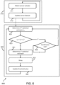
- Figure 4 illustrates a computer-implemented method 400 for distinguishing on which of the plurality of categories of flooring the nozzle of the vacuum cleaner is positioned.
- the plurality of categories of flooring includes the first category of flooring and the second, harder category of flooring.
- the method 400 comprises performing method 300 previously described, which includes a sensor data obtaining process 310 and a threshold defining process 320.
- the method 400 further comprises (iteratively) performing a floor category determination process 410.
- the floor category determination process 410 comprises a step 411 of obtaining the sensor dataset produced by the sensor data obtaining process 310; and a step 412 of determining a comparison value Vc of the sensor dataset.
- the comparison value is the comparison value for comparing to a threshold in order to distinguish or discriminate between different types of flooring, as previously described.
- the comparison value may be a statistical estimator of the sensor dataset, such as a predetermined percentile of the sensor dataset.
- the floor category determination process 410 also comprises a step 413 of defining a threshold breach value t b using the threshold value t v produced by the threshold value defining process 320.
- the threshold breach value defines the threshold to which the comparison value is to be compared in order to distinguish or discriminate between different types of flooring.
- the threshold breach value may be defined to have the same value as the threshold value produced by the threshold value defining process 320.
- t b t v .
- the threshold breach value may be a modified version of the threshold value produced by the threshold value defining process 320. Thus, one or more modifications may be made to the threshold value to produce the threshold breach value.
- the threshold value may be modified by summing the threshold value with a first biasing value X F (e.g., a so-called X-factor).
- X F e.g., a so-called X-factor
- the threshold value may be modified by multiplying the threshold value by a second biasing value M.
- M a second biasing value
- the floor category determination process 410 comprises a step 414 of determining that the nozzle of the vacuum cleaner is positioned on the first category of flooring responsive to the comparison value breaching the threshold breach value; and a step 415 of determining that the nozzle of the vacuum cleaner is positioned on the second category of flooring responsive to the comparison value failing to breach the threshold breach value.
- the floor category determination process 410 may comprise a determining step 416 of determining whether the comparison value breaches the threshold breach value, e.g., whether the comparison value is greater than the threshold breach value. Responsive to a positive determination in step 416, the process 410 performs step 414. Responsive to a negative determination step 416, the process 410 performs step 415.
- the vacuum cleaner may end the hard-floor mode, e.g., in step 417 and enter or otherwise operate in the soft-floor mode - e.g., and stop updating the threshold value. Otherwise, the method continues 418 to operate in the hard-floor mode.
- threshold value defining process 320 and the floor category determination process 410 make use of different (statistical) measures (e.g., statistical estimator(s) and/or value(s)) of the sensor data to: set the threshold value; define the threshold breach value and determine a comparison value to compare to the threshold breach value.
- statistic measures e.g., statistical estimator(s) and/or value(s)
- the processes 320 and 410 may be modified based on the precise implementation adopted.
- the comparison value is a percentile value of the sensor dataset (e.g., defined in step 312).
- a percentile value is a value that represents a predetermined percentile of the sensor values in the sensor dataset.
- the predetermined percentile may, for instance, be a Zth percentile, where Z is less than 50, e.g., between 10 and 50, e.g., between 20 and 30, e.g., 25.
- the first statistical estimator may be a mean or a trimmed mean of the sensor data.
- the first statistical estimator may be a mean average sensor value or a trimmed mean sensor value.
- Approaches for determining a mean or trimmed mean of plurality of values are well known in the art.
- the first statistical estimator may be a percentile value of the sensor dataset (e.g., defined in step 313).
- the predetermined percentile may, for instance, be a Yth percentile, where Y is less than 50, e.g., between 10 and 50, e.g., between 20 and 30, e.g., 25.
- the threshold value may be set, in step 322, using the first statistical estimator.
- the threshold value may be defined to be equal to the first statistical estimator and/or a (weighted) sum or average of the first statistical estimator and a previous threshold value.
- the threshold value may effectively be a moving (trimmed) average of the sensor value of the torque load dependent parameter.
- the threshold value may effectively be a moving average of the Yth percentile of iteratively obtained sensor data.
- the threshold breach value may be calculated by adding a biasing value to the threshold value.
- the threshold breach value is simply set to be equal to the threshold value.
- the determining step 416 may comprise determining whether a percentile value of the sensor dataset (the comparison value) is greater than the threshold breach value, which represents a moving average of previously values of the sensor dataset. Responsive to the comparison value exceeding the threshold breach value, it can be assumed that the nozzle of the vacuum is (no longer) positioned on the second category of flooring. Accordingly, if the vacuum cleaner is operating in the hard-floor mode and the comparison value breaches the threshold breach value, the vacuum cleaner may enter or otherwise operate in the soft-floor mode - e.g., and stop updating the threshold value.
- the comparison value is a first trimmed range of the sensor dataset (e.g., defined in step 312).
- the first statistical estimator may be a second trimmed mean of the sensor data.
- Approaches for determining a trimmed range are well known in the art.
- the second trimmed range is a range of a greater number of sensor values than the first trimmed range.
- the second trimmed range may be the interdecile range and the first trimmed range may be the interquartile range.
- the threshold value may be set, in step 322, using the first statistical estimator.
- the threshold value may be defined to be equal to the first statistical estimator and/or a (weighted) sum or average of the first statistical estimator and a previous threshold value.
- the threshold breach value may be calculated by multiplying the threshold value by a biasing value, e.g., following equation (3).
- the threshold breach value is simply set to be equal to the threshold value.
- the determining step 416 may comprise determining whether a second trimmed range of the sensor dataset (the comparison value) is greater than the threshold breach value. Responsive to the comparison value exceeding the threshold breach value, it can be assumed that the nozzle of the vacuum is (no longer) positioned on the second category of flooring. This approach recognizes that the dispersion of sensor data responsive to a torque load dependent parameter will increase if the nozzle is moved onto softer flooring.
- Figure 5 illustrates a variant to the method 500 previously disclosed.
- the method 500 differs in that the updating to the threshold value is delayed in a delay step 521.
- the delay step is configured at least to allow the method 400 to take place, e.g., to determine whether the nozzle is position on the first or second category of flooring.
- step 521 may be configured to delay any updating to the threshold value at least until it is confirmed that the nozzle is still on the second category of flooring. If it is determined, as a result of step 416, that the nozzle is positioned on the first category of flooring, then the hard-floor mode may end and the threshold value defining process 320 may terminate without updating the threshold value using the first statistical estimator. This reduces the risk that the threshold value will be (inaccurately) updated using a statistical estimator derived from a sensor dataset that contains one or more sample values obtained whilst the nozzle was on the first category of flooring.
- the length of the delay may be increased. This can be achieved, for instance by buffering the first statistical estimator for multiple iterations of processes 310 and 410.
- steps 321 and 521 are performed by determining the first statistical estimator and adding the first statistical estimator to a buffer.
- Step 321 is iteratively repeated (e.g., for each update to the sensor dataset in process 310) to iteratively add an instance of the first statistical estimator to the buffer.
- the Nth (i.e., oldest) first statistical estimator is used to perform step 322.
- Step 322 is then iteratively repeated, each time the buffer updates, using the oldest statistical estimator in the buffer. In this way, a delay is introduced between a sensor dataset being updated and the threshold value being updated.
- This delay facilitates a check to ensure that the statistical estimator (used to update the threshold value) is derived from a sensor dataset that is unlikely to contain one or more sample values obtained whilst the nozzle was on the first category of flooring (e.g., though performance of the process 410).
- the buffer may, in some instances, be no less than the length of the sensor dataset, e.g., equal to the length of the sensor dataset.
- step 412 may comprise identifying the earliest value in the buffer, i.e., the most recently inserted value.
- Figure 6 illustrates an advantageous variant to the method 300 previously described.
- Figure 6 illustrates an alternative method 600 for determining the threshold value for distinguishing on which of the plurality of categories of flooring the nozzle of a vacuum cleaner is positioned.
- the method 600 may be readily integrated with the method 400 or 500 previously disclosed.
- the updating of the threshold value is paused or postponed if there is a significant deviation or change in the torque load of the motor, e.g., caused by the nozzle of the vacuum cleaner being lifted (e.g., from the floor). It is recognized that the lifting of the nozzle will cause a significant drop in the torque load of the nozzle brush motor. If the updating to the threshold value were not paused, then a drop in the torque load would incorrectly update the threshold value, such that the threshold value would not correctly represent a hard-floor threshold value.
- the threshold value defining process 320 may comprise a step 621 of identifying a second statistical estimator of all sensor values in the sensor dataset.
- the threshold value defining process 320 may also comprise a sub-process 622 of, responsive to a difference between the second statistical estimator and the threshold value breaching (e.g., exceeding) a predetermined value, preventing the updating of the threshold value until one or more predetermined conditions are met.
- Step 622 may, for instance, comprise hanging the performing of the process 320 until the condition(s) are met.
- process 320 may comprise a step 623 of determining whether a difference between the second statistical estimator and the threshold value is more than the predetermined value. Responsive to a positive determination in step 623, the sub-process 622 is performed (until one or more predetermined conditions are met). Otherwise, the process 320 may continue.
- step 623 may comprise determining whether a sum of the second statistical estimator s 2 and the predetermined value X 2 is smaller than the threshold value t v .
- the second statistical estimator is a percentile value, being a predetermined percentile of all sensor values in the sensor data set.
- Step 623 preferably takes place before step 322, i.e., to make use of a non-updated version of the threshold value, to avoid updating the threshold value with incorrect data. In some examples, step 623 also takes place before performing step 321, to thereby avoid potentially unnecessary performance of step 321, achieving a more efficient method.
- Sub-process 622 may comprise hanging or pausing the threshold value defining process 320 until the one or more predetermined conditions are met.
- sub-process 622 may comprise hanging or pausing the threshold value defining process 320 until at least one of a plurality of sets of one or more predetermined conditions are met.
- the one or more predetermined conditions may comprise a predetermined period of time elapsing; a predetermined number of new sensor values being obtained; the difference between the second statistical estimator and the threshold value being less than the predetermined value; and/or an override indicator being received.
- the sub-process 622 is configured to stop pausing or hanging threshold value defining process at least when the difference between the second statistical estimator and the threshold value is no longer less than the predetermined value. This effectively resumes or restarts the threshold value defining process 320 when it is identified that the nozzle has been positioned back on the floor.
- a difference between the second statistical estimator and the threshold value is more than the predetermined value
- a blockage time counter will be started.
- the blockage time counter will continue to run whilst the difference between the second statistical estimator and the threshold value is more than the predetermined value.
- the threshold value defining process (particularly the performance of steps 321 and 322) will be resumed.
- the threshold value is modified using a weighted sum and/or average (e.g., using one or more predetermined weighting values).
- each predetermined weighting value may be modified, e.g., to more heavily favor or weight the previous threshold value. This effectively slows down the updating to the threshold value.
- the blockage time counter will be reset. In such an approach, if modified, the modification to each predetermined weighting value may be reverted.
- the technique for pausing updating a threshold can be applied to other techniques for performing automated updating of a threshold that are not described in the present disclosure.
- a computer-implemented method for controlling the operation of a threshold value update procedure wherein the threshold value update procedure is configured to iteratively update a threshold value for use in determining whether a nozzle of a vacuum cleaner is on a first category of flooring or a second, harder category of flooring.
- the computer-implemented method comprises: obtaining a sensor dataset comprising a plurality of sensor values, each sensor value being responsive to a torque load of a motor of the vacuum cleaner for rotating a brush located in the nozzle of the vacuum cleaner; identifying a second statistical estimator of all sensor values in the sensor dataset; and responsive to a difference between the second statistical estimator and the threshold value breaching the predetermined value, preventing the updating of the threshold value until one or more predetermined conditions are met.
- the vacuum cleaner may initially operate in a hard-floor mode.
- performance of the proposed method may be delayed (after power-up) at least until sufficient sensor data has been obtained and a determination made that the vacuum cleaner is positioned on a hard floor.
- the vacuum cleaner may switch to a hard-floor mode responsive to a detected transition between floor categories (using an elsewhere described approach).
- performance of the proposed method may be delayed (after switching to the hard-floor mode) at least until sufficient sensor data has been obtained and a determination made that the vacuum cleaner is positioned on the second category of flooring.
- the method for determining a threshold value is only performed during a hard-floor mode of operation and only after it is determined, upon entering the hard-floor mode, that the nozzle of the vacuum cleaner is positioned on the second category of flooring.
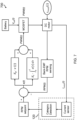
- Figure 7 illustrates a schematic overview of a (closed-loop) motor control system 700 for a brushed DC motor for rotating a brush in a nozzle of a vacuum cleaner, i.e., a nozzle brush motor, according to an embodiment of the invention.
- the motor control system determines a measure for the rotational speed of the brush by periodically stopping power supply to the motor for a short time (e.g., less than a millisecond), and measuring the back-emf voltage during this time. The back-emf voltage is then used as a measure for the rotational speed of the brush.
- the motor control system uses the feedback information about the rotational speed to operate a closed-loop system that ensures the rotational speed of the motor corresponds to the RPM setpoint.
- the motor control system may be operable in at least two modes, including the hard-floor mode and the soft-floor mode. This mirrors the hard-floor mode and the soft-floor mode of the vacuum clear. Thus, when the vacuum cleaner operates in the hard-floor mode, the motor control system operates in the hard-floor mode. Similarly, when the vacuum cleaner operates in the soft-floor mode, the motor control system operates in the soft-floor mode.
- the RPM setpoint for the motor may be dependent upon the mode of operation. For instance, the RPM setpoint may be set to be lower for the hard-floor mode than for the soft floor mode.
- the motor control system may be configured to switch its mode of operation responsive to a determined category of flooring. For instance, if a change of flooring category is detected whilst operating in the hard-floor mode, the motor control system may switch to the soft-floor mode. Similarly, if a change of flooring category whilst operating in the soft-floor mode, the motor control system may switch to the hard-floor mode.
- the processing system 120 is configured to detect a category of the flooring on which the nozzle is positioned., e.g., using sensor data responsive to a torque load of the motor, such as sensed electrical current values.
- the sensor data comprises samples or measures of the motor current (which changes responsive to the torque load of the motor).
- the motor current may be measured by measuring the voltage drop across a shunt resistor or by using a current sensor IC.
- the motor control system of a vacuum cleaner may be configured to start a vacuuming session in a hard-floor mode, i.e., when turned on.
- the (nozzle brush) motor may initially have a low RPM.
- a determination as to the category of flooring can be made, e.g., comparing to a pre-existing threshold value (e.g., stored in memory from a factory default or a previous vacuuming session). If it is determined that the nozzle of the vacuum cleaner is on the first category of flooring, then the motor control system may instead operate in the soft-floor mode (e.g., setting the RPM accordingly). Otherwise, previously described techniques for defining the threshold value may be performed.
- the above-described example proposes a technique for modifying a rotation speed of a brush (by changing the RPM setpoint) responsive to a determined category of flooring.
- One or more other properties of the vacuum cleaner may additionally and/or alternatively be set responsive to the determined category of flooring.
- the operation mode of one or more other control systems may also and/or otherwise be responsive to a detected category of flooring on which the nozzle is positioned.
- a second motor control system may control the suction power of the vacuum cleaner, e.g., by adjusting a speed of a motor that drives suction of the vacuum cleaner.
- the second motor control system is similarly operable in a hard-floor and soft-floor mode, and may switch modes in a similar manner to that previously described.
- the second control motor system may be configured to increase the suction power when operating in the soft-floor mode compared to the hard-floor mode.
- Previously described examples propose techniques that propose to control an operating mode of the vacuum cleaner responsive to a detected category of flooring.
- this approach is not essential.
- a detected category of flooring forms only part of the required conditions and/or criteria for defining or switching the operating mode of the vacuum cleaner.
- a switch from a soft-floor mode to a hard-floor mode may require at least: determination that the nozzle is (now) positioned on a hard floor (e.g., using a herein described approach) and detection of a transition between different categories of floor (using an elsewhere described approach).
- any other approach (described within this document or elsewhere) for determining a transition between categories of flooring upon which a nozzle of a vacuum could be employed.
- a switch from a hard-floor mode to a soft-floor mode may require: determination that the nozzle is (now) positioned on a soft floor (using a herein described approach) and detection of a transition between different categories of floor (using an elsewhere described approach).
- any other approach (described within this document or elsewhere) for determining a transition between categories of flooring upon which a nozzle of a vacuum could be employed.
- the approach may take the form of a computer implemented method configured to obtaining first sensor data, captured during a first period of time, wherein the first sensor data is responsive to a torque load of a nozzle brush motor of the vacuum cleaner for rotating a brush located in the nozzle of the vacuum cleaner; processing the first sensor data to generate a first transition trimmed estimator providing a predefined scale parameter of the first sensor data; obtaining second sensor data, captured during a second period of time, wherein the second sensor data is responsive to the torque load of the nozzle brush motor, and wherein the second period of time is later than the first period of time and partially overlaps the first period of time; processing the second sensor data to generate a second transition trimmed estimator providing the predefined scale parameter of the second sensor data; determining a difference between the first transition trimmed estimator and the second transition trimmed estimator; and responsive to the determined difference breaching a first
- each transition trimmed estimator is a statistical measure of dispersion that does not take account of outliers within the corresponding (instance of) sensor data.
- the transition trimmed estimator is a measure of dispersion within a central portion of the sensor data.
- the term transition trimmed estimator is well established in the field of statistical analysis.
- a scale parameter provides a statistical measure of dispersion, e.g., range, standard deviation or variance.
- the sensor data comprises a plurality or sequence of values representing the torque provided by a motor of the vacuum cleaner over a particular period or window of time.
- the purpose of the proposed method is to determine or predict whether a floor-category transition has occurred.
- the present disclosure recognizes that the dispersion of values within sensor data will change when the sensor data is for a period of time that includes a transition compared to sensor data for a period of time that does not include a transition. By monitoring the difference between statistical measures of dispersion (for different time periods), the occurrence of a transition can be detected.
- the proposed approach provides a noise-robust mechanism for detecting floor category transitions.
- the first transition trimmed estimator is a trimmed range of the first sensor data; and the second transition trimmed estimator is the trimmed range of the second sensor data.
- the first transition trimmed estimator is an interquartile range of the first sensor data; and the second transition trimmed estimator is the interquartile range of the second sensor data.
- An alternative label for the interquartile range is the 25% trimmed range.
- An alternative form of a trimmed range is an interdecile range (i.e., a 40% trimmed range). Other suitable types of trimmed ranges would be apparent to the skilled person (e.g., the 30% trimmed range or the 35% trimmed range).
- the first and second periods of time have the same length.
- each step of a flow chart may represent a different action performed by a processing system, and may be performed by a respective module of the processing system.
- the system makes use of a processing system to perform the data processing.
- the processing system can be implemented in numerous ways, with software and/or hardware, to perform the various functions required.
- the processing system typically employs one or more microprocessors that may be programmed using software (e.g., microcode) to perform the required functions.
- the processing system may be implemented as a combination of dedicated hardware to perform some functions and one or more programmed microprocessors and associated circuitry to perform other functions.
- circuitry examples include, but are not limited to, conventional microprocessors, application specific integrated circuits (ASICs), and field-programmable gate arrays (FPGAs).
- ASICs application specific integrated circuits
- FPGAs field-programmable gate arrays
- the processing system may be embodied as a digital and/or analog processing system.
- the processing system may be associated with one or more storage media such as volatile and non-volatile computer memory such as RAM, PROM, EPROM, and EEPROM.
- the storage media may be encoded with one or more programs that, when executed on one or more processing systems and/or controllers, perform the required functions.
- Various storage media may be fixed within a processing system or controller may be transportable, such that the one or more programs stored thereon can be loaded into a processing system.
- processing system may be implemented by a single processing system or by multiple separate processing units which may together be considered to constitute a "processing system". Such processing units may in some cases be remote from each other and communicate with each other in a wired or wireless manner.
- a computer program may be stored/distributed on a suitable medium, such as an optical storage medium or a solid-state medium supplied together with or as part of other hardware, but may also be distributed in other forms, such as via the Internet or other wired or wireless telecommunication systems.
- a suitable medium such as an optical storage medium or a solid-state medium supplied together with or as part of other hardware, but may also be distributed in other forms, such as via the Internet or other wired or wireless telecommunication systems.
Landscapes
- Engineering & Computer Science (AREA)
- Mechanical Engineering (AREA)
- Electric Vacuum Cleaner (AREA)
Abstract
Description
- The present invention relates to the field of vacuum cleaners.
- In the field of vacuum cleaners, a significant amount of research is being performed to improve energy efficiency. This is particularly important with the increasing use and availability of battery-powered vacuum cleaners (cordless vacuum cleaners), because the runtime, weight and cost of such cleaners heavily depend upon the battery capacity.
- To ensure sufficient run times with cordless vacuum cleaners, the suction power and hence air flow rate generated by such cordless vacuum cleaners are usually lower than those of conventional corded vacuum cleaners. To compensate for this decrease in suction power, most cordless vacuum cleaners include a nozzle containing a rotating brush. This increases and optimizes the cleaning performance of a cordless vacuum cleaner to make improved use of the limited amount of energy available in the battery.
- In order to meet desired dust pick-up (DPU) requirements, generally more air flow rate or suction power is required on soft floor categories/types compared to hard floors categories/types. To help the consumer to automatically optimize between run time and cleaning performance on different floor categories/types, adaptive vacuum cleaning modes have been introduced in which the suction power and/or rotational speed of the brush is automatically adjusted based on the floor category/type.
- It would therefore be desirable to provide a technique that can improve the accuracy of identifying a category/type of flooring on which the nozzle of a vacuum cleaner is positioned.
- The invention is defined by the claims.
- According to examples in accordance with an aspect of the invention, there is provided a computer-implemented method for determining a threshold value for use in distinguishing on which of a plurality of categories of flooring a nozzle of a vacuum cleaner is positioned, wherein the plurality of categories of flooring includes a first category of flooring and a second, harder category of flooring; and the vacuum cleaner is operable in a soft-floor mode for use when the nozzle is on the first category of flooring and a hard-floor mode for use when the nozzle is on the second category of flooring.
- The computer-implemented method comprises iteratively performing a sensor data obtaining process and a threshold value defining process.
- The sensor data obtaining process comprises: obtaining one or more new sensor values, each sensor value being a sample of a torque load dependent parameter that is responsive to a torque load of a motor of the vacuum cleaner for rotating a brush located in the nozzle of the vacuum cleaner; and adding the one or more sensor values to a sensor dataset comprising a plurality of sensor values.
- The threshold value defining process comprises processing all sensor values in the sensor dataset to determine a statistical estimator of the sensor dataset; and only when no less than a predetermined percentage of the sensor values in the sensor dataset were sampled when the vacuum cleaner was operating in the hard-floor mode, updating the threshold value using the determined statistical estimator, wherein the predetermined percentage is no less than 50%.
- It will be apparent that the sensor dataset comprises a plurality or sequence of values representing the torque provided by a motor of the vacuum cleaner over a particular period or window of time. The purpose of the proposed method is to use the sensor dataset to define or update a threshold against which a comparison value (derived from sensor data) can be compared. More particularly, the proposed approach updates the threshold only when the sensor dataset contains a majority of sensor values sampled during a hard-floor mode. Thus, the threshold is a hard-floor self-learning threshold. This advantageously allows the threshold to adapt to the specific conditions or environment in which the vacuum cleaner is used, e.g., to account for brush-floor interactions with different types of hard floor. The self-learning threshold also advantageously adapts the threshold to the natural changes in torque load that result from changes in the nature of the vacuum cleaner over time, e.g., degradation of any motors over time, buildup of debris, dust or dirt in the brush or vacuum cleaner and so on.
- One advantage of the proposed approach is that the torque load of a brush nozzle motor (being the motor of the vacuum cleaner for rotating a brush located in the nozzle of the vacuum cleaner) is significantly more stable when the nozzle is on a hard floor. Thus, by updating the threshold using data obtained only when operating in a hard-floor mode, the threshold for discriminating between hard floors and soft floors is more robust, stable, and less sensitive to noise, vacuuming styles and/or vacuuming motion(s) (e.g., forward and rearward movement of the nozzle). More reliable and accurate detection and determination of the floor category is therefore facilitated.
- The predetermined percentage is 100%. This approach advantageously avoids or reduces a likelihood that data obtained whilst the nozzle is on a soft floor will be used to update or modify the hard-floor self-learning threshold.
- The sensor data obtaining process further comprises removing one or more oldest sensor values from the sensor dataset. This provides a moving window of sensor data that is used to update the threshold value, thereby ensuring that the threshold value reflects the most recent conditions in which the vacuum cleaner is operating.
- The number of the new sensor values added to the sensor dataset and the oldest sensor values removed from the sensor dataset is preferably the same.
- The step of updating the threshold value may comprise: obtaining a previous threshold value, being a most recent update to the threshold value; and performing a weighted sum of the previous threshold value and the determined statistical estimator. This causes a gradual change or update to the threshold value over time. This avoids a sudden change of the threshold value that might be inaccurate (e.g., caused by noise or an undetected to a soft floor), providing more reliable and consistent discrimination between floor categories.
- In some examples, the step of performing a weighted sum comprises: multiplying the previous threshold value by a first predetermined weight to produce a first weighted value; multiplying the determined statistical estimator by a second predetermined weight to produce a second weighted value; and summing the first and second weighted values to determine the threshold value, wherein the sum of the first predetermined weight and the second predetermined weight is 1.
- Processing all sensor values in the sensor dataset may comprise averaging all sensor values in the sensor dataset to determine a mean average sensor value of the sensor dataset as the statistical estimator.
- Processing all sensor values in the sensor dataset may comprise determining a trimmed mean of the sensor values in the sensor dataset to determine a trimmed mean sensor value of the sensor dataset as the statistical estimator.
- The threshold value defining process may comprise: identifying a second statistical estimator of all sensor values in the sensor dataset; and responsive to a difference between the second statistical estimator and the threshold value breaching the predetermined value, preventing the updating of the threshold value until one or more predetermined conditions are met.
- This approach provides a technique for detecting or predicting when the nozzle has been lifted from a ground surface. In particular, the second statistical estimator may be compared to the threshold value to predict whether or not the nozzle has been lifted from a ground surface. In the event that such a lift is detected, the updating of the threshold value is paused. This approach helps to prevent or reduced a likelihood that a floor type recognition algorithm will fail in the case of a large interaction with the brush and the floor on hard floor types.
- The second statistical estimator may be a percentile value, being a predetermined percentile of all sensor values in the sensor data set. The predetermined percentile may be an Xth percentile of all sensor values in the sensor data, wherein the value for X is between 10 and 40.
- In some examples, the one or more predetermined conditions comprises one or more of: a predetermined period of time elapsing; a predetermined number of new sensor values being obtained; the difference between the second statistical estimator and the threshold value being less than the predetermined value; and/or an override indicator being received.
- There is also proposed a computer-implemented method for distinguishing on which of a plurality of categories of flooring a nozzle of a vacuum cleaner is positioned, the plurality of categories of flooring including a first category of flooring and a second, harder category of flooring.
- The computer-implemented method comprising determining a threshold value using a previously described method; and iteratively performing a floor category determination process.
- The floor category determination process comprises: obtaining the sensor dataset produced by the sensor data obtaining process; determining a comparison value by processing the sensor dataset; defining a threshold breach value using the threshold value produced by the threshold value defining process; determining that the nozzle of the vacuum cleaner is positioned on the first category of flooring responsive to the comparison value breaching the threshold breach value; and determining that the nozzle of the vacuum cleaner is positioned on the second category of flooring responsive to the comparison value failing to breach the threshold breach value.
- The statistical estimator may be a mean or trimmed mean of all sensor values in the sensor dataset; and the second statistical estimator may be a second predetermined percentile of all sensor values in the sensor dataset.
- There is also proposed a computer program product comprising computer program code means which, when executed on a computing device having a processing system, cause the processing system to perform all of the steps of any herein disclosed method.
- There is also proposed a processing system for determining a threshold value for use in distinguishing on which of a plurality of categories of flooring a nozzle of a vacuum cleaner is positioned, wherein the plurality of categories of flooring includes a first category of flooring and a second, harder category of flooring; and the vacuum cleaner is operable in a soft-floor mode for use when the nozzle is on the first category of flooring and a hard-floor mode for use when the nozzle is on the second category of flooring.
- The processing system is configured to iteratively perform a sensor data obtaining process and a threshold value defining process.
- The sensor data obtaining process comprises: obtaining one or more new sensor values, each sensor value being a sample of a torque load dependent parameter that is responsive to a torque load of a motor of the vacuum cleaner for rotating a brush located in the nozzle of the vacuum cleaner; and adding the one or more sensor values to a sensor dataset comprising a plurality of sensor values.
- The threshold value defining process comprises processing all sensor values in the sensor dataset to determine a statistical estimator of the sensor dataset; and only when no less than a predetermined percentage of the sensor values in the sensor dataset were sampled when the vacuum cleaner was operating in the hard-floor mode, updating the threshold value using the determined statistical estimator, wherein the predetermined percentage is no less than 50%.
- These and other aspects of the invention will be apparent from and elucidated with reference to the embodiment(s) described hereinafter.
- For a better understanding of the invention, and to show more clearly how it may be carried into effect, reference will now be made, by way of example only, to the accompanying drawings, in which:
-
Figure 1 illustrates a system in which embodiments may be implemented; -
Figure 2 illustrates a relationship between flooring hardness and motor current; -
Figure 3 is a flowchart illustrating a proposed method; -
Figure 4 is a flowchart illustrating another proposed approach; -
Figure 5 is a flowchart illustrating a variant to a proposed approach; -
Figure 6 is a flowchart illustrating a variant to the proposed approach; and -
Figure 7 illustrates a control scheme for a nozzle brush motor. - The invention will be described with reference to the Figures.
- It should be understood that the detailed description and specific examples, while indicating exemplary embodiments of the apparatus, systems and methods, are intended for purposes of illustration only and are not intended to limit the scope of the invention. These and other features, aspects, and advantages of the apparatus, systems and methods of the present invention will become better understood from the following description, appended claims, and accompanying drawings. It should be understood that the Figures are merely schematic and are not drawn to scale. It should also be understood that the same reference numerals are used throughout the Figures to indicate the same or similar parts.
- The invention provides a mechanism for defining a threshold for use in discriminating between on which of a plurality of different categories of flooring a nozzle of a vacuum cleaner is positioned. A threshold value is (iteratively) updated using sensor data obtained only when the vacuum cleaner operates in a hard-floor mode, such that the threshold value is a hard-floor self-learning threshold.
-
Figure 1 illustrates asystem 100, comprising a (cordless)vacuum cleaner 110 and aprocessing system 120. - The
vacuum cleaner 110 comprises anozzle 111 having abrush 112. A motor (not visible) of the vacuum cleaner is configured to rotate the brush 112 ("nozzle brush") located in thenozzle 111 of thevacuum cleaner 110. This motor may be labelled a nozzle brush motor for conciseness. The nozzle brush motor may be located in thenozzle 111 or elsewhere in the vacuum cleaner (e.g., connected to thebrush 112 via one or more linkages). - The vacuum cleaner is operable in two or more operational modes, including a soft-floor mode and a hard-floor mode. The soft-floor mode is designed for use when the nozzle is on a first category of flooring. The hard-floor mode is designed for use when the nozzle is on a second category of flooring, which is harder than the first category of flooring.
- In the context of the present disclosure and the field of vacuum cleaning generally, a hardness of a flooring refers to an amount of fabric or piles of a floor or to a measure of brush-floor interaction. In particular, harder floors will have less interaction with a nozzle brush 112 (during vacuuming of the floor) than softer floors. A hard floor will have no fabric or piles, e.g., have a smooth surface. A soft floor will comprise fabric or piles. Generally, the greater the amount of fabric or piles, the softer the floor.
- Thus, in the context of this specification, a "soft" floor is a category of flooring that experiences a higher brush-floor interaction than a hard floor.
- The vacuum cleaner is configured such that one or more operational properties of the vacuum cleaner differ when operating in the soft-floor mode compared to when operating in the hard-floor mode. This is due to the different demands for cleaning on floors having different levels of hardness. More generally, the value(s) of one or more operational properties of the vacuum cleaner will change dependent upon the operational mode of the vacuum cleaner.
- By way of example only, the rotation speed of the nozzle brush motor (and therefore the brush 112) may differ dependent upon the operational mode of the vacuum cleaner. For instance, the rotation speed may be greater when the vacuum cleaner is operating in the soft-floor mode than when operating in the hard-floor mode. A rotation speed (e.g., RPM) of the nozzle brush is therefore one example of an operational property.
- As another example, the suction power of the vacuum cleaner may differ dependent upon the operational mode of the vacuum cleaner. For instance, the suction power may be greater when the vacuum cleaner is operating in the soft-floor mode than when operating in the hard-floor mode. It is well known to the person skilled in the art that the suction power of a vacuum cleaner is dependent upon at least a speed of a vacuum motor for driving suction. Thus, in some examples, a speed of a vacuum motor is greater when the vacuum cleaner is operating in the soft-floor mode than when operating in the hard-floor mode. The suction power of the vacuum cleaner is therefore one example of an operational property.
- Other suitable examples of operational properties will be readily apparent to the skilled person in the art, and may depend upon the configuration or design of the vacuum cleaner.
- It will be apparent that it is important to be able to distinguish between on which of a plurality of different categories of flooring the nozzle is positioned, to determine or establish in which operational mode the vacuum cleaner should operate. In particular, it would be desirable to identify whether or not the nozzle is positioned on first category of flooring (a "soft floor") or a second category of flooring (a "hard floor"), which is harder than the first category of flooring.
- One approach for distinguishing between categories of flooring is to compare a comparison value to a threshold. The comparison value is derived from sensor data responsive to a torque load of the nozzle brush motor. The comparison value may, for instance, be a single instantaneous value of the torque load or a statistical estimator of the torque load.
- In general, a statistical estimator is derived by processing data comprising a plurality of values to derive the statistical estimator of a predetermined statistical property. Examples of statistical estimators include: a mean, a trimmed mean; a range; a trimmed range; a variance; a trimmed variance; a standard deviation; a trimmed standard deviation; or a percentile value (representing a particular percentile of the plurality of values). Other example statistical properties will be readily apparent to the skilled person, and include any measure of a location parameter or a scale parameter (e.g., a measure of dispersion).
-
Figure 2 illustrates a set ofbox plots 200 of motor current data for a nozzle brush motor with a fixed rotational speed setting for several different types of flooring. Thus, each box plot represents the range, spread and/or average of the motor torque load for different types of flooring. A motor current of a nozzle brush motor is sensitive/responsive (e.g., proportional) to a torque load of the motor. -
Floor # 0 is a hard floor, while the other floors are carpets (i.e., softer floors than the hard floor) with different thicknesses/type of pile. As shown inFigure 2 , the average torque load increases with reduced hardness of the floors. The precise variation between the different soft floors may depend upon a number of factors such as how the pile is woven (i.e., closed loop or open). -
Figure 2 thereby demonstrates how it is possible to make use of a torque load dependent parameter (also known as a torque load sensitive parameter) to distinguish or discriminate between different categories of flooring, having different levels of hardness. - The present disclosure proposes an approach for determining a threshold value for use in distinguishing in which of a plurality of categories of flooring the
nozzle 111 is positioned. - More particularly, it is herein proposed to set a threshold value using a first statistical estimator, examples of which have been previously described, of sensor data for which at least half of the sensor values (of the sensor data) were obtained only whilst the vacuum cleaner is operating in the hard-floor mode. Thus, the threshold value is defined using hard-floor mode sensor data.
-
Figure 3 is a flowchart that illustrates a computer-implementedmethod 300 for determining the threshold value. It will be clear that themethod 300 may be employed by the processing system previously described and/or illustrated. - The computer-implemented
method 300 comprises iteratively performing a sensordata obtaining process 310 and a thresholdvalue defining process 320. The sensordata obtaining processing 310 more formally defines the sensor data procedure briefly outlined above. - The sensor
data obtaining process 310 comprises astep 311 of obtaining one or more new sensor values. Each sensor value is a sample of a torque load dependent parameter that is responsive to a torque load of a motor of the vacuum cleaner for rotating a brush located in the nozzle of the vacuum cleaner. - One example of a torque load dependent parameter is a current drawn by the nozzle brush motor to rotate the brush. This current is proportional to the torque load. The current drawn by the motor can be sampled by, for instance, measuring the voltage drop over a shunt resistor located in same circuit as the motor or by using a current sensor IC. Other example approaches will be apparent to the skilled person.
- As another example, in the case of a nozzle brush motor that is controlled at a constant torque (i.e., draws a constant current), another example of a torque load dependent parameter is the rotational speed of the nozzle brush motor. Thus, in these circumstances, the rotational speed of the nozzle brush motor is a torque load dependent parameter.
- Other torque load dependent parameters will be apparent to the skilled person, such as a total power drawn by the nozzle brush motor and/or data produced by a torque transducer/sensor.
- The sensor
data obtaining process 310 also comprises astep 312 of adding the one or more sensor values to a sensor dataset comprising a plurality of sensor values. Thus, the sensor dataset will comprise a comprise a plurality of sensor values and be iteratively updated with one or more new sensor values obtained instep 311. - In some examples, the sensor
data obtaining process 310 further comprises removing 313 one or more oldest sensor values from the sensor dataset. Preferably, the number of the new sensor values added to the sensor dataset and the oldest sensor values removed from the sensor dataset is the same. - In this way, the sensor dataset may effectively represent a moving window of sensor values for a torque load dependent parameter, which is iteratively updated with new sample(s) of the torque load dependent parameter.
- The threshold
value defining process 320 comprises astep 321 of processing all sensor values in the sensor dataset to determine a first statistical estimator of the sensor dataset. Examples of suitable statistical estimators have been previously described, any of which may be employed as the first statistical estimator, but specific working examples will be provided later in this disclosure. - The threshold defining process also comprises a
step 322 of updating the threshold value using the determined first statistical estimator. - In one approach,
step 322 is performed by setting the threshold value to be equal to the determined first statistical estimator. - In another approach,
step 322 is performed by performing a (e.g., weighted) sum or average of the first statistical estimator and the previous value (i.e., the non-updated value) of the threshold value. Thus, step 322 may comprise obtaining a previous threshold value, being a most recent update to the threshold value; and performing a weighted sum of the previous threshold value and the determined statistical estimator. - As one example, a new threshold value tv can be determined using the following equation:

- Preferably, the value of α is between 0.5 and 1, e.g., 0.7 and 1, e.g., 0.9 and 1. This ensures that the updating to the threshold value is slow and gradual, to reduce a risk of sudden and inaccurate changes to the threshold value.
- In this way,
step 322 may be performed by multiplying the previous threshold value by a first predetermined weight to produce a first weighted value; multiplying the determined statistical estimator by a second predetermined weight to produce a second weighted value; and summing the first and second weighted values to determine the threshold value. The sum of the first predetermined weight and the second predetermined weight is 1. - At
least step 322 is performed only when no less than a predetermined percentage of the sensor values in the sensor dataset were sampled when the vacuum cleaner was operating in the hard-floor mode. The predetermined percentage is no less than 50%, e.g., no less than 75%, e.g., 100%. In this way, the threshold value is only updated using a first statistical estimator of sensor values of which a majority were obtained only when the vacuum cleaner was operating in the hard-floor mode. The threshold value can thereby be considered to be a hard-floor threshold value. - In some variations, the entire threshold value defining process is only performed when no less than a predetermined percentage of the sensor values in the sensor dataset were sampled when the vacuum cleaner was operating in the hard-floor mode.
- In some variations, both
processes -
Figure 4 illustrates a computer-implementedmethod 400 for distinguishing on which of the plurality of categories of flooring the nozzle of the vacuum cleaner is positioned. As previously mentioned, the plurality of categories of flooring includes the first category of flooring and the second, harder category of flooring. - The
method 400 comprises performingmethod 300 previously described, which includes a sensordata obtaining process 310 and athreshold defining process 320. - The
method 400 further comprises (iteratively) performing a floorcategory determination process 410. - The floor
category determination process 410 comprises astep 411 of obtaining the sensor dataset produced by the sensordata obtaining process 310; and astep 412 of determining a comparison value Vc of the sensor dataset. The comparison value is the comparison value for comparing to a threshold in order to distinguish or discriminate between different types of flooring, as previously described. - By way of preferred example, the comparison value may be a statistical estimator of the sensor dataset, such as a predetermined percentile of the sensor dataset.
- The floor
category determination process 410 also comprises astep 413 of defining a threshold breach value tb using the threshold value tv produced by the thresholdvalue defining process 320. The threshold breach value defines the threshold to which the comparison value is to be compared in order to distinguish or discriminate between different types of flooring. - In some embodiments, the threshold breach value may be defined to have the same value as the threshold value produced by the threshold
value defining process 320. Thus, in some examples, tb = tv. - In other examples, the threshold breach value may be a modified version of the threshold value produced by the threshold
value defining process 320. Thus, one or more modifications may be made to the threshold value to produce the threshold breach value. - For instance, the threshold value may be modified by summing the threshold value with a first biasing value XF (e.g., a so-called X-factor). This can be mathematically represented by the following equation:

- As another example, the threshold value may be modified by multiplying the threshold value by a second biasing value M. This can be mathematically represented by the following equation:

- Of course, a combination of these techniques could be performed, e.g., multiplying the threshold value tv by the second biasing value M before adding the first biasing value - or adding the first biasing value to the threshold value and the multiplying the sum by the second biasing value.
- The floor
category determination process 410 comprises astep 414 of determining that the nozzle of the vacuum cleaner is positioned on the first category of flooring responsive to the comparison value breaching the threshold breach value; and astep 415 of determining that the nozzle of the vacuum cleaner is positioned on the second category of flooring responsive to the comparison value failing to breach the threshold breach value. - In particular, the floor
category determination process 410 may comprise a determiningstep 416 of determining whether the comparison value breaches the threshold breach value, e.g., whether the comparison value is greater than the threshold breach value. Responsive to a positive determination instep 416, theprocess 410 performsstep 414. Responsive to anegative determination step 416, theprocess 410 performsstep 415. - It will be appreciated that if the vacuum cleaner is operating in the hard-floor mode and the comparison value breaches the threshold breach value, the vacuum cleaner may end the hard-floor mode, e.g., in
step 417 and enter or otherwise operate in the soft-floor mode - e.g., and stop updating the threshold value. Otherwise, the method continues 418 to operate in the hard-floor mode. - There are a wide variety of potential approaches for performing the threshold
value defining process 320 and the floorcategory determination process 410 which make use of different (statistical) measures (e.g., statistical estimator(s) and/or value(s)) of the sensor data to: set the threshold value; define the threshold breach value and determine a comparison value to compare to the threshold breach value. The skilled person will appreciate that theprocesses - For improved contextual understanding, a number of working examples will be hereafter described.
- In one working example, the comparison value is a percentile value of the sensor dataset (e.g., defined in step 312). A percentile value is a value that represents a predetermined percentile of the sensor values in the sensor dataset. The predetermined percentile may, for instance, be a Zth percentile, where Z is less than 50, e.g., between 10 and 50, e.g., between 20 and 30, e.g., 25.
- In a first variation of this working example, the first statistical estimator may be a mean or a trimmed mean of the sensor data. Thus, the first statistical estimator may be a mean average sensor value or a trimmed mean sensor value. Approaches for determining a mean or trimmed mean of plurality of values are well known in the art.
- In a second variation of this working example, the first statistical estimator may be a percentile value of the sensor dataset (e.g., defined in step 313). The predetermined percentile may, for instance, be a Yth percentile, where Y is less than 50, e.g., between 10 and 50, e.g., between 20 and 30, e.g., 25.
- The threshold value may be set, in
step 322, using the first statistical estimator. For example, the threshold value may be defined to be equal to the first statistical estimator and/or a (weighted) sum or average of the first statistical estimator and a previous threshold value. - In this way, for the first variation of this working example, the threshold value may effectively be a moving (trimmed) average of the sensor value of the torque load dependent parameter. Similarly, for the second variation of this working example, the threshold value may effectively be a moving average of the Yth percentile of iteratively obtained sensor data.
- The threshold breach value may be calculated by adding a biasing value to the threshold value. However, in an alternative example, the threshold breach value is simply set to be equal to the threshold value.
- Accordingly, the determining
step 416 may comprise determining whether a percentile value of the sensor dataset (the comparison value) is greater than the threshold breach value, which represents a moving average of previously values of the sensor dataset. Responsive to the comparison value exceeding the threshold breach value, it can be assumed that the nozzle of the vacuum is (no longer) positioned on the second category of flooring. Accordingly, if the vacuum cleaner is operating in the hard-floor mode and the comparison value breaches the threshold breach value, the vacuum cleaner may enter or otherwise operate in the soft-floor mode - e.g., and stop updating the threshold value. - As another working example, the comparison value is a first trimmed range of the sensor dataset (e.g., defined in step 312).
- In this working example, the first statistical estimator may be a second trimmed mean of the sensor data. Approaches for determining a trimmed range are well known in the art. In preferred examples, the second trimmed range is a range of a greater number of sensor values than the first trimmed range. For instance, the second trimmed range may be the interdecile range and the first trimmed range may be the interquartile range.
- The threshold value may be set, in
step 322, using the first statistical estimator. For example, the threshold value may be defined to be equal to the first statistical estimator and/or a (weighted) sum or average of the first statistical estimator and a previous threshold value. - The threshold breach value may be calculated by multiplying the threshold value by a biasing value, e.g., following equation (3). However, in an alternative example, the threshold breach value is simply set to be equal to the threshold value.
- Accordingly, the determining
step 416 may comprise determining whether a second trimmed range of the sensor dataset (the comparison value) is greater than the threshold breach value. Responsive to the comparison value exceeding the threshold breach value, it can be assumed that the nozzle of the vacuum is (no longer) positioned on the second category of flooring. This approach recognizes that the dispersion of sensor data responsive to a torque load dependent parameter will increase if the nozzle is moved onto softer flooring. - Other suitable examples for performing the threshold
value defining process 320 and the floorcategory determination process 410 using different combinations of first statistical parameters, comparison values and/or threshold (breach) value calculation processes will be apparent to the appropriately skilled person. -
Figure 5 illustrates a variant to themethod 500 previously disclosed. - The
method 500 differs in that the updating to the threshold value is delayed in adelay step 521. The delay step is configured at least to allow themethod 400 to take place, e.g., to determine whether the nozzle is position on the first or second category of flooring. - In particular,
step 521 may be configured to delay any updating to the threshold value at least until it is confirmed that the nozzle is still on the second category of flooring. If it is determined, as a result ofstep 416, that the nozzle is positioned on the first category of flooring, then the hard-floor mode may end and the thresholdvalue defining process 320 may terminate without updating the threshold value using the first statistical estimator. This reduces the risk that the threshold value will be (inaccurately) updated using a statistical estimator derived from a sensor dataset that contains one or more sample values obtained whilst the nozzle was on the first category of flooring. - To further reduce this risk, the length of the delay may be increased. This can be achieved, for instance by buffering the first statistical estimator for multiple iterations of
processes - In one example, steps 321 and 521 are performed by determining the first statistical estimator and adding the first statistical estimator to a buffer. Step 321 is iteratively repeated (e.g., for each update to the sensor dataset in process 310) to iteratively add an instance of the first statistical estimator to the buffer. When the buffer is full, the Nth (i.e., oldest) first statistical estimator is used to perform
step 322. Step 322 is then iteratively repeated, each time the buffer updates, using the oldest statistical estimator in the buffer. In this way, a delay is introduced between a sensor dataset being updated and the threshold value being updated. This delay facilitates a check to ensure that the statistical estimator (used to update the threshold value) is derived from a sensor dataset that is unlikely to contain one or more sample values obtained whilst the nozzle was on the first category of flooring (e.g., though performance of the process 410). - The buffer may, in some instances, be no less than the length of the sensor dataset, e.g., equal to the length of the sensor dataset.
- In some examples, the same type of statistical estimator is used as the first statistical estimator and the comparison value Vc. In some such examples, the earliest value in the buffer (produced by
steps 321 and 521) may be used as the comparison value Vc. Thus, step 412 may comprise identifying the earliest value in the buffer, i.e., the most recently inserted value. -
Figure 6 illustrates an advantageous variant to themethod 300 previously described. Thus,Figure 6 illustrates analternative method 600 for determining the threshold value for distinguishing on which of the plurality of categories of flooring the nozzle of a vacuum cleaner is positioned. Themethod 600 may be readily integrated with themethod - In this variant, the updating of the threshold value is paused or postponed if there is a significant deviation or change in the torque load of the motor, e.g., caused by the nozzle of the vacuum cleaner being lifted (e.g., from the floor). It is recognized that the lifting of the nozzle will cause a significant drop in the torque load of the nozzle brush motor. If the updating to the threshold value were not paused, then a drop in the torque load would incorrectly update the threshold value, such that the threshold value would not correctly represent a hard-floor threshold value.
- Accordingly, the threshold
value defining process 320 may comprise astep 621 of identifying a second statistical estimator of all sensor values in the sensor dataset. - The threshold
value defining process 320 may also comprise a sub-process 622 of, responsive to a difference between the second statistical estimator and the threshold value breaching (e.g., exceeding) a predetermined value, preventing the updating of the threshold value until one or more predetermined conditions are met. Step 622 may, for instance, comprise hanging the performing of theprocess 320 until the condition(s) are met. - In particular,
process 320 may comprise astep 623 of determining whether a difference between the second statistical estimator and the threshold value is more than the predetermined value. Responsive to a positive determination instep 623, the sub-process 622 is performed (until one or more predetermined conditions are met). Otherwise, theprocess 320 may continue. - As a working example, step 623 may comprise determining whether a sum of the second statistical estimator s2 and the predetermined value X2 is smaller than the threshold value tv.
- The second statistical estimator is a percentile value, being a predetermined percentile of all sensor values in the sensor data set. Preferably, the second statistical estimator is an Xth percentile of all sensor values in the sensor data, wherein the value for X is between 10 and 40, e.g., X = 25.
- Step 623 preferably takes place before
step 322, i.e., to make use of a non-updated version of the threshold value, to avoid updating the threshold value with incorrect data. In some examples, step 623 also takes place before performingstep 321, to thereby avoid potentially unnecessary performance ofstep 321, achieving a more efficient method. -
Sub-process 622 may comprise hanging or pausing the thresholdvalue defining process 320 until the one or more predetermined conditions are met. In particular, sub-process 622 may comprise hanging or pausing the thresholdvalue defining process 320 until at least one of a plurality of sets of one or more predetermined conditions are met. - A wide variety of potential predetermined conditions are considered. As a non-exhaustive list of examples, the one or more predetermined conditions may comprise a predetermined period of time elapsing; a predetermined number of new sensor values being obtained; the difference between the second statistical estimator and the threshold value being less than the predetermined value; and/or an override indicator being received.
- Preferably, the sub-process 622 is configured to stop pausing or hanging threshold value defining process at least when the difference between the second statistical estimator and the threshold value is no longer less than the predetermined value. This effectively resumes or restarts the threshold
value defining process 320 when it is identified that the nozzle has been positioned back on the floor. - In one variant of this approach, a difference between the second statistical estimator and the threshold value is more than the predetermined value, a blockage time counter will be started. The blockage time counter will continue to run whilst the difference between the second statistical estimator and the threshold value is more than the predetermined value. When the blockage time counter reaches a blockage time counter threshold, then the threshold value defining process (particularly the performance of
steps 321 and 322) will be resumed. In this variant, the threshold value is modified using a weighted sum and/or average (e.g., using one or more predetermined weighting values). Preferably, if the threshold value defining process is resumed due to the blockage time counter reaching the blockage time counter threshold, then each predetermined weighting value may be modified, e.g., to more heavily favor or weight the previous threshold value. This effectively slows down the updating to the threshold value. When the difference between the second statistical estimator and the threshold value is no longer less than the predetermined value, the blockage time counter will be reset. In such an approach, if modified, the modification to each predetermined weighting value may be reverted. - The technique for pausing updating a threshold (particularly a self-learning threshold) can be applied to other techniques for performing automated updating of a threshold that are not described in the present disclosure.
- Accordingly, there is also herein proposed a computer-implemented method for controlling the operation of a threshold value update procedure, wherein the threshold value update procedure is configured to iteratively update a threshold value for use in determining whether a nozzle of a vacuum cleaner is on a first category of flooring or a second, harder category of flooring.
- The computer-implemented method comprises: obtaining a sensor dataset comprising a plurality of sensor values, each sensor value being responsive to a torque load of a motor of the vacuum cleaner for rotating a brush located in the nozzle of the vacuum cleaner; identifying a second statistical estimator of all sensor values in the sensor dataset; and responsive to a difference between the second statistical estimator and the threshold value breaching the predetermined value, preventing the updating of the threshold value until one or more predetermined conditions are met.
- Above-described methods are used to update a threshold value using sensor data obtained during a hard-floor mode. It will be appreciated that the proposed method for updating the threshold value does not need to be performed for the entire time that the vacuum cleaner is operating in the hard-floor mode.
- For instance, upon powering up, the vacuum cleaner may initially operate in a hard-floor mode. However, performance of the proposed method may be delayed (after power-up) at least until sufficient sensor data has been obtained and a determination made that the vacuum cleaner is positioned on a hard floor.
- As another example, the vacuum cleaner may switch to a hard-floor mode responsive to a detected transition between floor categories (using an elsewhere described approach). However, performance of the proposed method may be delayed (after switching to the hard-floor mode) at least until sufficient sensor data has been obtained and a determination made that the vacuum cleaner is positioned on the second category of flooring.
- Thus, in some examples, the method for determining a threshold value is only performed during a hard-floor mode of operation and only after it is determined, upon entering the hard-floor mode, that the nozzle of the vacuum cleaner is positioned on the second category of flooring.
-
Figure 7 illustrates a schematic overview of a (closed-loop)motor control system 700 for a brushed DC motor for rotating a brush in a nozzle of a vacuum cleaner, i.e., a nozzle brush motor, according to an embodiment of the invention. - The motor control system determines a measure for the rotational speed of the brush by periodically stopping power supply to the motor for a short time (e.g., less than a millisecond), and measuring the back-emf voltage during this time. The back-emf voltage is then used as a measure for the rotational speed of the brush. The motor control system uses the feedback information about the rotational speed to operate a closed-loop system that ensures the rotational speed of the motor corresponds to the RPM setpoint.
- The motor control system may be operable in at least two modes, including the hard-floor mode and the soft-floor mode. This mirrors the hard-floor mode and the soft-floor mode of the vacuum clear. Thus, when the vacuum cleaner operates in the hard-floor mode, the motor control system operates in the hard-floor mode. Similarly, when the vacuum cleaner operates in the soft-floor mode, the motor control system operates in the soft-floor mode.
- The RPM setpoint for the motor may be dependent upon the mode of operation. For instance, the RPM setpoint may be set to be lower for the hard-floor mode than for the soft floor mode.
- The motor control system may be configured to switch its mode of operation responsive to a determined category of flooring. For instance, if a change of flooring category is detected whilst operating in the hard-floor mode, the motor control system may switch to the soft-floor mode. Similarly, if a change of flooring category whilst operating in the soft-floor mode, the motor control system may switch to the hard-floor mode.
- The
processing system 120 is configured to detect a category of the flooring on which the nozzle is positioned., e.g., using sensor data responsive to a torque load of the motor, such as sensed electrical current values. - As previously explained, detection of a category of flooring makes use of sensor data responsive to a torque load of the motor. In some examples, the sensor data comprises samples or measures of the motor current (which changes responsive to the torque load of the motor). The motor current may be measured by measuring the voltage drop across a shunt resistor or by using a current sensor IC.
- For example, the motor control system of a vacuum cleaner may be configured to start a vacuuming session in a hard-floor mode, i.e., when turned on. Thus, the (nozzle brush) motor may initially have a low RPM. Once sufficient sensor data has been obtained, a determination as to the category of flooring can be made, e.g., comparing to a pre-existing threshold value (e.g., stored in memory from a factory default or a previous vacuuming session). If it is determined that the nozzle of the vacuum cleaner is on the first category of flooring, then the motor control system may instead operate in the soft-floor mode (e.g., setting the RPM accordingly). Otherwise, previously described techniques for defining the threshold value may be performed.
- When the RPM setpoint is changed from a lower setting to a higher setting (or vice versa), the brush rotational speed error increases, and the motor control system adjusts the output (PWM duty cycle) to minimize the error.
- The above-described example proposes a technique for modifying a rotation speed of a brush (by changing the RPM setpoint) responsive to a determined category of flooring. One or more other properties of the vacuum cleaner may additionally and/or alternatively be set responsive to the determined category of flooring.
- In particular, the operation mode of one or more other control systems may also and/or otherwise be responsive to a detected category of flooring on which the nozzle is positioned.
- As an example, a second motor control system may control the suction power of the vacuum cleaner, e.g., by adjusting a speed of a motor that drives suction of the vacuum cleaner. In some examples, the second motor control system is similarly operable in a hard-floor and soft-floor mode, and may switch modes in a similar manner to that previously described. The second control motor system may be configured to increase the suction power when operating in the soft-floor mode compared to the hard-floor mode.
- Previously described examples propose techniques that propose to control an operating mode of the vacuum cleaner responsive to a detected category of flooring. However, this approach is not essential. In some variations, a detected category of flooring forms only part of the required conditions and/or criteria for defining or switching the operating mode of the vacuum cleaner.
- By way of example, to reduce a risk of false switching, a switch from a soft-floor mode to a hard-floor mode (for any control system) may require at least: determination that the nozzle is (now) positioned on a hard floor (e.g., using a herein described approach) and detection of a transition between different categories of floor (using an elsewhere described approach). In particular, any other approach (described within this document or elsewhere) for determining a transition between categories of flooring upon which a nozzle of a vacuum could be employed.
- Similarly, as another example, to reduce a risk of false switching, a switch from a hard-floor mode to a soft-floor mode (for any control system) may require: determination that the nozzle is (now) positioned on a soft floor (using a herein described approach) and detection of a transition between different categories of floor (using an elsewhere described approach). In particular, any other approach (described within this document or elsewhere) for determining a transition between categories of flooring upon which a nozzle of a vacuum could be employed.
- One example approach for identifying a transition of a nozzle of a vacuum cleaner from being positioned on different categories of flooring is hereafter described for the sake of completeness. The approach may take the form of a computer implemented method configured to obtaining first sensor data, captured during a first period of time, wherein the first sensor data is responsive to a torque load of a nozzle brush motor of the vacuum cleaner for rotating a brush located in the nozzle of the vacuum cleaner; processing the first sensor data to generate a first transition trimmed estimator providing a predefined scale parameter of the first sensor data; obtaining second sensor data, captured during a second period of time, wherein the second sensor data is responsive to the torque load of the nozzle brush motor, and wherein the second period of time is later than the first period of time and partially overlaps the first period of time; processing the second sensor data to generate a second transition trimmed estimator providing the predefined scale parameter of the second sensor data; determining a difference between the first transition trimmed estimator and the second transition trimmed estimator; and responsive to the determined difference breaching a first predetermined threshold, determining that the nozzle has transitioned from being positioned on the first category of flooring to the second category of flooring.
- In the context of the present disclosure, each transition trimmed estimator is a statistical measure of dispersion that does not take account of outliers within the corresponding (instance of) sensor data. Thus, the transition trimmed estimator is a measure of dispersion within a central portion of the sensor data. The term transition trimmed estimator is well established in the field of statistical analysis. A scale parameter provides a statistical measure of dispersion, e.g., range, standard deviation or variance.
- It will be apparent that the sensor data comprises a plurality or sequence of values representing the torque provided by a motor of the vacuum cleaner over a particular period or window of time. The purpose of the proposed method is to determine or predict whether a floor-category transition has occurred.
- The present disclosure recognizes that the dispersion of values within sensor data will change when the sensor data is for a period of time that includes a transition compared to sensor data for a period of time that does not include a transition. By monitoring the difference between statistical measures of dispersion (for different time periods), the occurrence of a transition can be detected. The proposed approach provides a noise-robust mechanism for detecting floor category transitions.
- In some examples, the first transition trimmed estimator is a trimmed range of the first sensor data; and the second transition trimmed estimator is the trimmed range of the second sensor data.
- Optionally, the first transition trimmed estimator is an interquartile range of the first sensor data; and the second transition trimmed estimator is the interquartile range of the second sensor data. An alternative label for the interquartile range is the 25% trimmed range. An alternative form of a trimmed range is an interdecile range (i.e., a 40% trimmed range). Other suitable types of trimmed ranges would be apparent to the skilled person (e.g., the 30% trimmed range or the 35% trimmed range).
- In some examples, no less than 50% of the second period of time overlaps the first period of time.
- Optionally, the first and second periods of time have the same length.
- The skilled person would be readily capable of developing a processing system for carrying out any herein described method. Thus, each step of a flow chart may represent a different action performed by a processing system, and may be performed by a respective module of the processing system.
- As discussed above, the system makes use of a processing system to perform the data processing. The processing system can be implemented in numerous ways, with software and/or hardware, to perform the various functions required. The processing system typically employs one or more microprocessors that may be programmed using software (e.g., microcode) to perform the required functions. The processing system may be implemented as a combination of dedicated hardware to perform some functions and one or more programmed microprocessors and associated circuitry to perform other functions.
- Examples of circuitry that may be employed in various embodiments of the present disclosure include, but are not limited to, conventional microprocessors, application specific integrated circuits (ASICs), and field-programmable gate arrays (FPGAs). Thus, the processing system may be embodied as a digital and/or analog processing system.
- In various implementations, the processing system may be associated with one or more storage media such as volatile and non-volatile computer memory such as RAM, PROM, EPROM, and EEPROM. The storage media may be encoded with one or more programs that, when executed on one or more processing systems and/or controllers, perform the required functions. Various storage media may be fixed within a processing system or controller may be transportable, such that the one or more programs stored thereon can be loaded into a processing system.
- Variations to the disclosed embodiments can be understood and effected by those skilled in the art in practicing the claimed invention, from a study of the drawings, the disclosure, and the appended claims. In the claims, the word "comprising" does not exclude other elements or steps, and the indefinite article "a" or "an" does not exclude a plurality.
- Functions implemented by a processing system may be implemented by a single processing system or by multiple separate processing units which may together be considered to constitute a "processing system". Such processing units may in some cases be remote from each other and communicate with each other in a wired or wireless manner.
- The mere fact that certain measures are recited in mutually different dependent claims does not indicate that a combination of these measures cannot be used to advantage.
- A computer program may be stored/distributed on a suitable medium, such as an optical storage medium or a solid-state medium supplied together with or as part of other hardware, but may also be distributed in other forms, such as via the Internet or other wired or wireless telecommunication systems.
- If the term "adapted to" is used in the claims or description, it is noted the term "adapted to" is intended to be equivalent to the term "configured to". If the term "arrangement" is used in the claims or description, it is noted the term "arrangement" is intended to be equivalent to the term "system", and vice versa.
- Any reference signs in the claims should not be construed as limiting the scope.
Claims (15)
- A computer-implemented method for determining a threshold value for use in distinguishing on which of a plurality of categories of flooring a nozzle of a vacuum cleaner is positioned, wherein:the plurality of categories of flooring includes a first category of flooring and a second, harder category of flooring;the vacuum cleaner is operable in a soft-floor mode for use when the nozzle is on the first category of flooring and a hard-floor mode for use when the nozzle is on the second category of flooring; andthe computer-implemented method comprises iteratively performing a sensor data obtaining process and a threshold value defining process,wherein the sensor data obtaining process comprises:obtaining one or more new sensor values, each sensor value being a sample of a torque load dependent parameter that is responsive to a torque load of a motor of the vacuum cleaner for rotating a brush located in the nozzle of the vacuum cleaner; andadding the one or more sensor values to a sensor dataset comprising a plurality of sensor values;wherein the threshold value defining process comprises:processing all sensor values in the sensor dataset to determine a statistical estimator of the sensor dataset; andonly when no less than a predetermined percentage of the sensor values in the sensor dataset were sampled when the vacuum cleaner was operating in the hard-floor mode, updating the threshold value using the determined statistical estimator, wherein the predetermined percentage is no less than 50%.
- The computer-implemented method of claim 1, wherein the predetermined percentage is 100%.
- The computer-implemented method of claim 1 or 2, wherein the sensor data obtaining process further comprises removing one or more oldest sensor values from the sensor dataset.
- The computer-implemented method of claim 3, wherein the number of the new sensor values added to the sensor dataset and the oldest sensor values removed from the sensor dataset is the same.
- The computer-implemented method of any of claims 1 to 4, wherein the step of updating the threshold value comprises:obtaining a previous threshold value, being a most recent update to the threshold value; andperforming a weighted sum of the previous threshold value and the determined statistical estimator.
- The computer-implemented method of claim 5, wherein the step of performing a weighted sum comprises:multiplying the previous threshold value by a first predetermined weight to produce a first weighted value;multiplying the determined statistical estimator by a second predetermined weight to produce a second weighted value;summing the first and second weighted values to determine the threshold value,wherein the sum of the first predetermined weight and the second predetermined weight is 1.
- The computer-implemented method of any of claims 1 to 6, wherein processing all sensor values in the sensor dataset comprises averaging all sensor values in the sensor dataset to determine a mean average sensor value of the sensor dataset as the statistical estimator.
- The computer-implemented method of any of claims 1 to 6, wherein processing all sensor values in the sensor dataset comprises determining a trimmed mean of the sensor values in the sensor dataset to determine a trimmed mean sensor value of the sensor dataset as the statistical estimator.
- The computer-implemented method of any of claims 1 to 8, wherein the threshold value defining process comprises:identifying a second statistical estimator of all sensor values in the sensor dataset; andresponsive to a difference between the second statistical estimator and the threshold value breaching the predetermined value, preventing the updating of the threshold value until one or more predetermined conditions are met.
- The computer-implemented method of claim 9, wherein the second statistical estimator is a percentile value, being a predetermined percentile of all sensor values in the sensor data set.
- The computer-implemented method of claim 10, wherein the predetermined percentile is an Xth percentile of all sensor values in the sensor data, wherein the value for X is between 10 and 40.
- The computer-implemented method of any of claims 9 to 11, wherein the one or more predetermined conditions comprises one or more of:a predetermined period of time elapsing;a predetermined number of new sensor values being obtained;the difference between the second statistical estimator and the threshold value being less than the predetermined value; and/oran override indicator being received.
- A computer-implemented method for distinguishing on which of a plurality of categories of flooring a nozzle of a vacuum cleaner is positioned, the plurality of categories of flooring including a first category of flooring and a second, harder category of flooring,the computer-implemented method comprising determining a threshold value using the method of any of claims 1 to 12; anditeratively performing a floor category determination process comprising:obtaining the sensor dataset produced by the sensor data obtaining process;determining a comparison value by processing the sensor dataset;defining a threshold breach value using the threshold value produced by the threshold value defining process;determining that the nozzle of the vacuum cleaner is positioned on the first category of flooring responsive to the comparison value breaching the threshold breach value; anddetermining that the nozzle of the vacuum cleaner is positioned on the second category of flooring responsive to the comparison value failing to breach the threshold breach value.
- A computer program product comprising computer program code means which, when executed on a computing device having a processing system, cause the processing system to perform all of the steps of the method according to any of claims 1 to 13.
- A processing system for determining a threshold value for use in distinguishing on which of a plurality of categories of flooring a nozzle of a vacuum cleaner is positioned, wherein:the plurality of categories of flooring includes a first category of flooring and a second, harder category of flooring;the vacuum cleaner is operable in a soft-floor mode for use when the nozzle is on the first category of flooring and a hard-floor mode for use when the nozzle is on the second category of flooring; andthe processing system is configured to iteratively perform a sensor data obtaining process and a threshold value defining process,wherein the sensor data obtaining process comprises:obtaining one or more new sensor values, each sensor value being a sample of a torque load dependent parameter that is responsive to a torque load of a motor of the vacuum cleaner for rotating a brush located in the nozzle of the vacuum cleaner; andadding the one or more sensor values to a sensor dataset comprising a plurality of sensor values; andwherein the threshold value defining process comprises:processing all sensor values in the sensor dataset to determine a statistical estimator of the sensor dataset; andonly when no less than a predetermined percentage of the sensor values in the sensor dataset were sampled when the vacuum cleaner was operating in the hard-floor mode, updating the threshold value using the determined statistical estimator, wherein the predetermined percentage is no less than 50%.
Priority Applications (3)
| Application Number | Priority Date | Filing Date | Title |
|---|---|---|---|
| EP23191668.5A EP4509028B1 (en) | 2023-08-16 | 2023-08-16 | Identifying different categories of flooring |
| PCT/EP2024/069202 WO2025036612A1 (en) | 2023-08-16 | 2024-07-08 | Identifying different categories of flooring |
| CN202480053502.2A CN121793879A (en) | 2023-08-16 | 2024-07-08 | Identifying different categories of floors |
Applications Claiming Priority (1)
| Application Number | Priority Date | Filing Date | Title |
|---|---|---|---|
| EP23191668.5A EP4509028B1 (en) | 2023-08-16 | 2023-08-16 | Identifying different categories of flooring |
Publications (2)
| Publication Number | Publication Date |
|---|---|
| EP4509028A1 true EP4509028A1 (en) | 2025-02-19 |
| EP4509028B1 EP4509028B1 (en) | 2026-04-08 |
Family
ID=87580155
Family Applications (1)
| Application Number | Title | Priority Date | Filing Date |
|---|---|---|---|
| EP23191668.5A Active EP4509028B1 (en) | 2023-08-16 | 2023-08-16 | Identifying different categories of flooring |
Country Status (3)
| Country | Link |
|---|---|
| EP (1) | EP4509028B1 (en) |
| CN (1) | CN121793879A (en) |
| WO (1) | WO2025036612A1 (en) |
Citations (1)
| Publication number | Priority date | Publication date | Assignee | Title |
|---|---|---|---|---|
| US20190365177A1 (en) * | 2015-06-30 | 2019-12-05 | Techtronic Industries Co. Ltd. | Vacuum cleaner with brushroll control |
-
2023
- 2023-08-16 EP EP23191668.5A patent/EP4509028B1/en active Active
-
2024
- 2024-07-08 WO PCT/EP2024/069202 patent/WO2025036612A1/en active Pending
- 2024-07-08 CN CN202480053502.2A patent/CN121793879A/en active Pending
Patent Citations (1)
| Publication number | Priority date | Publication date | Assignee | Title |
|---|---|---|---|---|
| US20190365177A1 (en) * | 2015-06-30 | 2019-12-05 | Techtronic Industries Co. Ltd. | Vacuum cleaner with brushroll control |
Also Published As
| Publication number | Publication date |
|---|---|
| WO2025036612A1 (en) | 2025-02-20 |
| CN121793879A (en) | 2026-04-03 |
| EP4509028B1 (en) | 2026-04-08 |
Similar Documents
| Publication | Publication Date | Title |
|---|---|---|
| CN213665062U (en) | Vacuum cleaners and surface treatment equipment | |
| US20220257076A1 (en) | Vacuum cleaner and method of controlling a motor for a brush of the vacuum cleaner | |
| CN110594956B (en) | A filter screen dirty blocking detection method, device and air conditioner | |
| US9901233B2 (en) | Air filter monitoring | |
| CN111397091B (en) | Filter screen filth blockage determining method and device, storage medium and air conditioner | |
| WO2021012884A1 (en) | Control method and apparatus for automatically emptying water pump, corresponding device, and storage medium | |
| CN109028460B (en) | Air conditioner filter screen filth blockage determination method and device and air conditioner | |
| EP3476509B1 (en) | Method and apparatus for controlling electric tool, and electric tool | |
| CN113237189B (en) | Direct current motor starting control method and device, air conditioner and computer readable storage medium | |
| CN111938510A (en) | Cleaning robot, surface type detection method and control method | |
| CN112438659B (en) | Floor sweeping robot and method for recognizing ground environment by same | |
| CN1164825A (en) | Vacuum cleaner with power control in dependence on mode of operation of electrical brush | |
| EP4509028B1 (en) | Identifying different categories of flooring | |
| CN117386653A (en) | Detection method for oil stain weight of fan blade and range hood | |
| CN114689790B (en) | Sensor data calibration method, sensor data calibration device and range hood | |
| EP4509027A1 (en) | Identifying a transition between different categories of flooring | |
| US20190316579A1 (en) | Pump control system and operating method thereof | |
| JP2004084458A (en) | Open / close body pinch detection device | |
| US11022110B2 (en) | Pump control system and abnormal processing and recovering method thereof | |
| EP4626289B1 (en) | Identifying a category of flooring | |
| CN114923542B (en) | Sewage bucket state identification method and operation method of cleaning machine | |
| US12053142B2 (en) | Mobile robot operation control method for safety management of cleaning module and apparatus therefor | |
| EP1389059B1 (en) | A control method for a vacuum cleaner | |
| KR102660026B1 (en) | Method and Apparatus for Controlling the Operation of a Mobile Robot for Safety Management of Cleaning Module | |
| CN116065913B (en) | Anti-pinch control system for car window and car |
Legal Events
| Date | Code | Title | Description |
|---|---|---|---|
| PUAI | Public reference made under article 153(3) epc to a published international application that has entered the european phase |
Free format text: ORIGINAL CODE: 0009012 |
|
| STAA | Information on the status of an ep patent application or granted ep patent |
Free format text: STATUS: THE APPLICATION HAS BEEN PUBLISHED |
|
| AK | Designated contracting states |
Kind code of ref document: A1 Designated state(s): AL AT BE BG CH CY CZ DE DK EE ES FI FR GB GR HR HU IE IS IT LI LT LU LV MC ME MK MT NL NO PL PT RO RS SE SI SK SM TR |
|
| STAA | Information on the status of an ep patent application or granted ep patent |
Free format text: STATUS: REQUEST FOR EXAMINATION WAS MADE |
|
| 17P | Request for examination filed |
Effective date: 20250801 |
|
| GRAP | Despatch of communication of intention to grant a patent |
Free format text: ORIGINAL CODE: EPIDOSNIGR1 |
|
| STAA | Information on the status of an ep patent application or granted ep patent |
Free format text: STATUS: GRANT OF PATENT IS INTENDED |
|
| INTG | Intention to grant announced |
Effective date: 20251222 |
|
| GRAS | Grant fee paid |
Free format text: ORIGINAL CODE: EPIDOSNIGR3 |
|
| GRAA | (expected) grant |
Free format text: ORIGINAL CODE: 0009210 |
|
| STAA | Information on the status of an ep patent application or granted ep patent |
Free format text: STATUS: THE PATENT HAS BEEN GRANTED |
|
| AK | Designated contracting states |
Kind code of ref document: B1 Designated state(s): AL AT BE BG CH CY CZ DE DK EE ES FI FR GB GR HR HU IE IS IT LI LT LU LV MC ME MK MT NL NO PL PT RO RS SE SI SK SM TR |
|
| REG | Reference to a national code |
Ref country code: CH Ref legal event code: F10 Free format text: ST27 STATUS EVENT CODE: U-0-0-F10-F00 (AS PROVIDED BY THE NATIONAL OFFICE) Effective date: 20260408 Ref country code: GB Ref legal event code: FG4D |
|
| REG | Reference to a national code |
Ref country code: DE Ref legal event code: R096 Ref document number: 602023014767 Country of ref document: DE |