EP4509025A1 - Preventing electrostatic buildup at a surface of a core part of a vacuum cleaner unit - Google Patents
Preventing electrostatic buildup at a surface of a core part of a vacuum cleaner unit Download PDFInfo
- Publication number
- EP4509025A1 EP4509025A1 EP23191731.1A EP23191731A EP4509025A1 EP 4509025 A1 EP4509025 A1 EP 4509025A1 EP 23191731 A EP23191731 A EP 23191731A EP 4509025 A1 EP4509025 A1 EP 4509025A1
- Authority
- EP
- European Patent Office
- Prior art keywords
- vacuum cleaner
- core part
- cleaner unit
- exterior surface
- dirt
- Prior art date
- Legal status (The legal status is an assumption and is not a legal conclusion. Google has not performed a legal analysis and makes no representation as to the accuracy of the status listed.)
- Withdrawn
Links
Images


Classifications
-
- A—HUMAN NECESSITIES
- A47—FURNITURE; DOMESTIC ARTICLES OR APPLIANCES; COFFEE MILLS; SPICE MILLS; SUCTION CLEANERS IN GENERAL
- A47L—DOMESTIC WASHING OR CLEANING; SUCTION CLEANERS IN GENERAL
- A47L5/00—Structural features of suction cleaners
- A47L5/12—Structural features of suction cleaners with power-driven air-pumps or air-compressors, e.g. driven by motor vehicle engine vacuum
- A47L5/22—Structural features of suction cleaners with power-driven air-pumps or air-compressors, e.g. driven by motor vehicle engine vacuum with rotary fans
- A47L5/24—Hand-supported suction cleaners
- A47L5/26—Hand-supported suction cleaners with driven dust-loosening tools
-
- A—HUMAN NECESSITIES
- A47—FURNITURE; DOMESTIC ARTICLES OR APPLIANCES; COFFEE MILLS; SPICE MILLS; SUCTION CLEANERS IN GENERAL
- A47L—DOMESTIC WASHING OR CLEANING; SUCTION CLEANERS IN GENERAL
- A47L11/00—Machines for cleaning floors, carpets, furniture, walls, or wall coverings
- A47L11/40—Parts or details of machines not provided for in groups A47L11/02 - A47L11/38, or not restricted to one of these groups, e.g. handles, arrangements of switches, skirts, buffers, levers
- A47L11/4027—Filtering or separating contaminants or debris
-
- A—HUMAN NECESSITIES
- A47—FURNITURE; DOMESTIC ARTICLES OR APPLIANCES; COFFEE MILLS; SPICE MILLS; SUCTION CLEANERS IN GENERAL
- A47L—DOMESTIC WASHING OR CLEANING; SUCTION CLEANERS IN GENERAL
- A47L9/00—Details or accessories of suction cleaners, e.g. mechanical means for controlling the suction or for effecting pulsating action; Storing devices specially adapted to suction cleaners or parts thereof; Carrying-vehicles specially adapted for suction cleaners
- A47L9/10—Filters; Dust separators; Dust removal; Automatic exchange of filters
- A47L9/16—Arrangement or disposition of cyclones or other devices with centrifugal action
- A47L9/1608—Cyclonic chamber constructions
-
- A—HUMAN NECESSITIES
- A47—FURNITURE; DOMESTIC ARTICLES OR APPLIANCES; COFFEE MILLS; SPICE MILLS; SUCTION CLEANERS IN GENERAL
- A47L—DOMESTIC WASHING OR CLEANING; SUCTION CLEANERS IN GENERAL
- A47L9/00—Details or accessories of suction cleaners, e.g. mechanical means for controlling the suction or for effecting pulsating action; Storing devices specially adapted to suction cleaners or parts thereof; Carrying-vehicles specially adapted for suction cleaners
- A47L9/10—Filters; Dust separators; Dust removal; Automatic exchange of filters
- A47L9/16—Arrangement or disposition of cyclones or other devices with centrifugal action
- A47L9/1683—Dust collecting chambers; Dust collecting receptacles
Definitions
- the invention relates to a vacuum cleaner unit configured to be used in a vacuum cleaner and to receive incoming dirt-laden air in the vacuum cleaner and to bring about separation of dirt and air
- the vacuum cleaner unit comprising: a core part including a cleaned air discharge arrangement extending along a cyclone axis of rotation, which cleaned air discharge arrangement is configured to discharge air from the vacuum cleaner unit; an annular air swirling chamber surrounding the cleaned air discharge arrangement in a direction about the cyclone axis of rotation; and at least one inlet configured to let in dirt-laden air to the air swirling chamber; wherein the cleaned air discharge arrangement has inwardly protruding vanes and gaps between the vanes.
- the invention also relates to a vacuum cleaner, preferably of the handheld type, comprising a conduit, a suction nozzle at an end of the conduit, a vacuum cleaner unit as mentioned here before, connected to the conduit, and an arrangement configured to generate air suction forces at the position of the suction nozzle and an air flow from the suction nozzle towards the vacuum cleaner unit, through the conduit.
- the invention is in the field of vacuum cleaning and vacuum cleaners, particularly vacuum cleaners comprising a vacuum cleaner unit that is designed to separate dirt and air and to rely on an air swirling movement about a cleaned air discharge arrangement in the process.
- a term commonly used to denote the vacuum cleaner unit is cyclone unit, and a term commonly used to denote the cleaned air discharge arrangement is vortex finder.
- a practical example of dirt is dust.
- all of the terms dirt, dust and dirt particles are used, as appropriate in the respective text portions.
- the vacuum cleaner can be a handheld vacuum cleaner.
- the vacuum cleaner is battery-operated, a very flexible proposition is obtained, and market results demonstrate that such a type of vacuum cleaner is getting more and more popular. More and more people are inclined to use such a vacuum cleaner as the first/preferred vacuum cleaner in the house rather than only an in-between cleaner. This is mostly due to the ease of use. Contrary to a canister type of vacuum cleaner, the handheld vacuum cleaner is easy to maneuver and lift.
- WO 2022/002591 A1 discloses a vacuum cleaner, comprising: a dirt inlet; a motor and fan for delivering suction to the dirt inlet; a cyclone unit for separating particles from a flow generated by the suction of the motor and fan, comprising a vortex finder extending along a cyclone axis of rotation and an annular chamber formed around the outside of the vortex finder; and a delivery duct for delivering air to the cyclone unit such that the air can flow to the annular chamber.
- the vacuum cleaner for example comprises a head having the dirt inlet, and the delivery duct comprises a tube connecting the head to the cyclone unit.
- the vacuum cleaner for example comprises a stick vacuum cleaner.
- the dirt collection chamber is in a side-by-side arrangement with the annular chamber, and is particularly coupled to a space that is present between a ceiling of the annular chamber and a forward end of the vortex finder.
- Cyclone units are widely used as a means to separate dry particles from air. Cyclone units are also used to separate water droplets (and dirt particles) from air in the case of wet vacuum cleaners.
- the vortex finder that is included in the cyclone unit forms part of a core part of the cyclone unit and typically has a central arrangement in the annular chamber.
- the vortex finder is provided in the form of a hollow cylinder-shaped plastic part with gaps along the length for enabling air to flow from the annular chamber to inside the vortex finder and be further transported from that position to a position where the air exits the cyclone unit.
- WO 2021/140041 A1 discloses that the vortex finder can have vanes around which incoming air is guided into the vortex finder. Having such a configuration of the vortex finder adds to the separation performance of the cyclone unit.
- the invention provides a vacuum cleaner unit configured to be used in a vacuum cleaner and to receive incoming dirt-laden air in the vacuum cleaner and to bring about separation of dirt and air, the vacuum cleaner unit comprising: a core part including a cleaned air discharge arrangement extending along a cyclone axis of rotation, which cleaned air discharge arrangement is configured to discharge air from the vacuum cleaner unit; an annular air swirling chamber surrounding the cleaned air discharge arrangement in the direction about the cyclone axis of rotation; and at least one inlet configured to let in dirt-laden air to the air swirling chamber; wherein the cleaned air discharge arrangement has inwardly protruding vanes and gaps between the vanes; and wherein the core part is configured to prevent electrostatic buildup at the position of at least a portion of an exterior surface of the core part.
- a unique feature of the invention is the core part being configured to prevent electrostatic buildup at the position of at least a portion of an exterior surface of the core part.
- the core part is configured to prevent electrostatic buildup at the position of at least a major portion of the exterior surface. It may be practical if the anti-static measures of the invention are realized across substantially the entire exterior surface of the core part, which is very well possible when the anti-static measures involve the core part being made of an appropriate material, and also when the anti-static measures involve the core part comprising an appropriate exterior finishing layer.
- the invention covers two main options, namely an option of the core part comprising a material configured to not allow for electric charge transfer from dirt particles rubbing against the exterior surface, at least at the position of the exterior surface, and an option of the core part comprising material configured to lead electric charges obtained by dirt particles rubbing against the exterior surface away from the exterior surface, at least at the position of the exterior surface.
- the cleaned air discharge arrangement comprises an electrically conductive material, at least at the position of the exterior surface.
- the core part comprises a thermoplastic polymer with an electrically conductive additive such as carbon.
- the core part is provided with an electrically conductive exterior finishing layer.
- the core part is provided with an exterior finishing layer of a spray paint with an electrically conductive additive such as carbon or zinc.
- the material of the core part or the exterior finishing layer should have a low enough resistivity ( ⁇ ) and enough volume (material thickness h) to store the charges away from the surface.
- ⁇ material resistivity
- h material thickness.
- m a molecular weight
- N A the Avogradro constant, which is 6 ⁇ 10 23 .
- ⁇ m 1.5 ⁇ 10 3 kg m 3
- m a 300 g mol .
- N 3 ⁇ 10 27 m -3 .
- the electric field from a charged plate is related to the surface charge.
- V ⁇ 1 ⁇ Ne E ⁇ ⁇ V ⁇ ⁇ 1 3 ⁇ 10 27 ⁇ 65 ⁇ 10 4 ⁇ 1.6 ⁇ 10 ⁇ 19 ⁇ 2 ⁇ 10 3 5 ⁇ 10 ⁇ 3 ⁇ 1.3 ⁇ 10 ⁇ 9 m s .
- V ⁇ 1 ⁇ Ne E ⁇ ⁇ V ⁇ ⁇ 7 ⁇ 10 ⁇ 12 m s , which is relatively slow taking into account an atomic layer thickness and a typical time that dirt particles are present in cyclone.
- m a 10 5 gr mol ⁇ N ⁇ 9 ⁇ 10 24 m ⁇ 3
- V ⁇ 1 ⁇ Ne E ⁇ ⁇ V ⁇ ⁇ 3.5 ⁇ 10 ⁇ 9 m s , which is relatively fast taking into account an atomic layer thickness and a typical time that dirt particles are present in cyclone.
- A effective area of contact
- m A ⁇ 0.03 0.0225 1.33 kg m 2
- N A m a ⁇ p ⁇ ⁇ 6 ⁇ D p 3
- the charge per area is equal to N A ⁇ f ⁇ e f represents the number of elementary charges.
- N N represents the number of charges per volume.
- sufficient capacity is available when the layer thickness is 0.5 ⁇ m and more preferably in a range of 1 to 5 ⁇ m.
- sufficient capacity is available when the material configured to lead electric charges obtained by dirt particles rubbing against the exterior surface away from the exterior surface is present in the core part at least in an exterior layer of a thickness of at least 0.5 ⁇ m, more preferably a thickness in a range of 1 to 5 ⁇ m.
- material having a resistivity ⁇ that is lower than 10 10 ⁇ m, preferably lower than 10 9 ⁇ m, and more preferably lower than 10 8 ⁇ m.
- the vacuum cleaner unit comprises a dirt collection chamber configured to receive and store dirt of the dirt-laden air, wherein the dirt collection chamber is located in the extension of the cleaned air discharge arrangement and the air swirling chamber.
- Advantages of such a location of the dirt collection chamber include a possibility to have a design of the vacuum cleaner unit that is compact and provides the vacuum cleaner unit with an appealing elongated look, and also a possibility to shape an entrance to the dirt collection chamber in such a way that relatively large particles such as leaves can reach the dirt collection chamber more easily.
- the core part of the vacuum cleaner unit includes an extension body extending along the cyclone axis of rotation, in the extension of the cleaned air discharge arrangement and towards the dirt collection chamber.
- an extension body has a function in dissipating energy from an air flow that is at a position between the cleaned air discharge arrangement and the dirt collection chamber, so that a risk that air at the position of the dirt collection chamber brings about displacement of dirt from the dirt collection chamber is minimized.
- the core part is configured to prevent electrostatic buildup at the position of at least a portion of the exterior surface of the core part located at the extension body.
- the cleaned air discharge arrangement is generally tube-shaped, having both a circular interior periphery and a circular exterior periphery.
- the gaps between the vanes of the cleaned air discharge arrangement are generally elongated, extending in a direction of the cyclone axis of rotation.
- a practical example of an entrance width of the gaps i.e. an entrance dimension of the gaps in the direction about the cyclone axis of rotation, is an entrance width of about 1 mm.
- the vanes of the cleaned air discharge arrangement have a generally wing-shaped profile.
- the core part includes an extension body
- the extension body is generally tube-shaped, having both a circular interior periphery and a circular exterior periphery, wherein it is possible yet not essential if the exterior of the extension body is flush with the exterior of the cleaned air discharge arrangement.
- the core part includes a guide part configured to guide incoming dirt-laden air to follow a coil-shaped path towards the cleaned air discharge arrangement.
- the presence of such a guide part contributes to generating and maintaining the cyclone.
- the core part is configured to prevent electrostatic buildup at the position of at least a portion of the exterior surface of the core part located at the guide part.
- this measure is meant to avoid a situation in which dirt particles are enabled to pass through the gaps of the cleaned air discharge arrangement from a position on the exterior surface of the core part, which may otherwise happen due to dirt particles sticking to the exterior surface and only experiencing very limited drag forces and centrifugal forces there, which forces are insufficient to detach the dirt particles from the surface.
- the invention also relates to a vacuum cleaner comprising a conduit, a suction nozzle at an end of the conduit, a vacuum cleaner unit as defined and described in the foregoing, connected to the conduit, and an arrangement configured to generate air suction forces at the position of the suction nozzle and an air flow from the suction nozzle towards the vacuum cleaner unit, through the conduit.
- the vacuum cleaner may be particularly be of the handheld type, but that does not alter the fact that other types of vacuum cleaner are covered by the invention as well.
- the vacuum cleaner according to the invention can be a vacuum cleaner of the canister type, a vacuum cleaner of the stick type, a vacuum cleaner of the upright type, a vacuum cleaner of the robotic type, or a sweeper.
- the invention is in the field of vacuum cleaning and vacuum cleaners, particularly vacuum cleaners comprising a vacuum cleaner unit that is designed to separate dirt and air.
- a vacuum cleaner 1 that is of the handheld type and that includes a vacuum cleaner unit 2 according to an embodiment of the invention is illustrated in figure 1 .
- the vacuum cleaner 1 comprises a conduit 3, a suction nozzle 4 at an end of the conduit 3, the vacuum cleaner unit 2 connected to the conduit 3, and an arrangement 5 configured to generate air suction forces at the position of the suction nozzle 4 and an air flow from the suction nozzle 4 towards the vacuum cleaner unit 2, through the conduit 3, which arrangement 5 normally includes a suitable type of motor.
- the handheld vacuum cleaner 1 may be provided as a removable part of a larger vacuum cleaner such as a stick vacuum cleaner, but it is also possible that the handheld vacuum cleaner 1 is provided as a standalone device. Normally, a front side of the vacuum cleaner 1 is defined as the side where the suction nozzle 4 is present and a back side of the vacuum cleaner 1 is defined as the side where the arrangement 5 including the motor is present. In figure 1 , the vacuum cleaner 1 is shown in a generally horizontal orientation. For the purpose of cleaning floors and other surfaces that can be reached from above, the vacuum cleaner 1 is to be held in a downward orientation, i.e.
- the vacuum cleaner 1 is to be held in an upward orientation, i.e. an orientation with the suction nozzle 4 pointing upwards.
- Operating the handheld vacuum cleaner 1 involves putting the arrangement 5 including the motor to an activated state, so that air suction forces are generated at the position of the suction nozzle 4.
- a person using the vacuum cleaner 1 holds the vacuum cleaner 1 in a position in which the suction nozzle 4 is close to or on a surface to be cleaned, dirt is removed from the surface under the influence of the air suction forces, wherein the dirt is carried to inside the suction nozzle 4 and the conduit 3, along with air.
- the dirt-laden air is made to move towards the vacuum cleaner unit 2 and is supplied to the vacuum cleaner unit 2 at the position of an inlet 6 of the vacuum cleaner unit 2.
- the vacuum cleaner unit 2 is designed to separate dirt and air.
- the vacuum cleaner unit 2 is equipped with a cleaned air discharge arrangement 10 extending along a cyclone axis of rotation A R , and has an annular air swirling chamber 11 surrounding the cleaned air discharge arrangement 10 in a direction about the cyclone axis of rotation A R .
- a sectional view of the cleaned air discharge arrangement 10 is separately shown in figure 6 .
- the cleaned air discharge arrangement 10 is generally shaped like a hollow cylinder provided with inwardly protruding vanes 12 and gaps 13 between the vanes 12, which gaps 13 are of elongated shape, extending in the direction about the cyclone axis of rotation A R .
- the vacuum cleaner unit 2 further has a dirt collection chamber 14.
- the above-mentioned inlet 6 of the vacuum cleaner unit 2 is particularly at a position for letting in dirt-laden air to the air swirling chamber 11.
- the cleaned air discharge arrangement 10 is configured to discharge air from the vacuum cleaner unit 2, while the dirt collection chamber 14 is configured to receive and store dirt of the dirt-laden air.
- an air swirling movement about the cleaned air discharge arrangement 10 in the air swirling chamber 11 is promoted on the basis of a number of factors.
- the dirt-laden air is let in tangentially to the air swirling chamber 11 at a side position on the vacuum cleaner unit 2
- the vacuum cleaner unit 2 is equipped with a guide part 15 that is arranged and shaped such that the incoming air is guided to follow a coil-shaped path, and in the third place, surfaces having a circular outline are generally present in the vacuum cleaner unit 2, as can best be seen in figure 3 .
- the spiraling movement of the air in the vacuum cleaner unit 2 is illustrated in figures 4 and 5 .
- the dirt collection chamber 14 is located in the extension of the cleaned air discharge arrangement 10 and the air swirling chamber 11 so that the dirt collection chamber 14 is located further down the cleaned air discharge arrangement 10 and the air swirling chamber 11 in the direction of the cyclone axis of rotation A R .
- the vacuum cleaner unit 2 comprises an extension body 16 extending along the cyclone axis of rotation A R , in the extension of the cleaned air discharge arrangement 10 and towards the dirt collection chamber 14.
- the extension body 16 is generally tube-shaped, having both a circular interior periphery and a circular exterior periphery.
- the extension body 16 has a function in ensuring that a minimum of energy is present in the air at the position of the dirt collection chamber 14, so that a risk that dirt in the dirt collection chamber 14 is agitated by the air and thereby displaced from the dirt collection chamber 14 is minimized.
- a choice of materials for use in the vacuum cleaner unit 2 is made in view of a desire to have optimal separation performance of the vacuum cleaner unit 2.
- measures are taken so that a core part 17 of the vacuum cleaner unit 2 is configured to prevent electrostatic buildup at the position of at least a portion of an exterior surface 18 of the core part 17.
- the core part 17 comprises the cleaned air discharge arrangement 10.
- the core part 17 comprises all three of the cleaned air discharge arrangement 10, the guide part 15 and the extension body 16, i.e. all of the components extending along the cyclone axis of rotation A R at a core position of the cyclone.
- the measures according to the invention are aimed at avoiding a situation in which dirt particles are drawn towards the exterior surface 18 of the core part 17 and are made to stick to the exterior surface 18 on the basis of electrostatic forces.
- the fact is that if such a situation occurs, there is a risk of reduction of the separation performance of the vacuum cleaner unit 2.
- the reason is that at the very position of the exterior surface 18, forces acting to cause the dirt particles to move away from the exterior surface 18 are generally lower than the electrostatic forces, so that the dirt particles are free to reach the gaps 13 of the cleaned air discharge arrangement 10 from a position on the exterior surface 18.
- the measures of the invention may be realized by using a material in the core part 17 that is configured to not allow for electric charge transfer from dirt particles rubbing against the exterior surface 18, at least at the position of the exterior surface 18, or by using a material in the core part 17 that is configured to lead electric charges obtained by dirt particles rubbing against the exterior surface 18 away from the exterior surface 18, at least at the position of the exterior surface 18.
- the core part 17 comprises an electrically conductive material, at least at the position of the exterior surface 18, or that the core part 17 is provided with an electrically conductive exterior finishing layer.
- a vacuum cleaner unit 2 comprising a core part 17 including a cleaned air discharge arrangement 10 and an annular air swirling chamber 11 surrounding the cleaned air discharge arrangement 10, the core part 17 is configured to prevent electrostatic buildup at the position of at least a portion of an exterior surface 18 of the core part 17.
- the core part 17 comprises at least at the position of the exterior surface 18 material that is configured to not allow for a triboelectric effect following from dirt particles rubbing or sliding against the exterior surface 18.
- electrically conductive material is used in the core part 17, probably in an exterior finishing layer of the core part 17, such that electric charges can be led away from the exterior surface 18.
Landscapes
- Engineering & Computer Science (AREA)
- Mechanical Engineering (AREA)
- Filters For Electric Vacuum Cleaners (AREA)
Abstract
In a vacuum cleaner unit (2) comprising a core part (17) including a cleaned air discharge arrangement (10) and an annular air swirling chamber (11), the core part (17) is configured to prevent electrostatic buildup at the position of at least a portion of an exterior surface (18) of the core part (17). In this way, beneficial effects to the separation performance of the unit (2) are obtained. According to one practical option, the core part (17) comprises at least at the position of the exterior surface (18) material that is configured to not allow for a triboelectric effect following from dirt particles rubbing or sliding against the exterior surface (18). According to another practical option, electrically conductive material is used in the core part (17), probably in an exterior finishing layer of the core part (17), such that electric charges can be led away from the exterior surface (18).
Description
- The invention relates to a vacuum cleaner unit configured to be used in a vacuum cleaner and to receive incoming dirt-laden air in the vacuum cleaner and to bring about separation of dirt and air, the vacuum cleaner unit comprising: a core part including a cleaned air discharge arrangement extending along a cyclone axis of rotation, which cleaned air discharge arrangement is configured to discharge air from the vacuum cleaner unit; an annular air swirling chamber surrounding the cleaned air discharge arrangement in a direction about the cyclone axis of rotation; and at least one inlet configured to let in dirt-laden air to the air swirling chamber; wherein the cleaned air discharge arrangement has inwardly protruding vanes and gaps between the vanes.
- The invention also relates to a vacuum cleaner, preferably of the handheld type, comprising a conduit, a suction nozzle at an end of the conduit, a vacuum cleaner unit as mentioned here before, connected to the conduit, and an arrangement configured to generate air suction forces at the position of the suction nozzle and an air flow from the suction nozzle towards the vacuum cleaner unit, through the conduit.
- The invention is in the field of vacuum cleaning and vacuum cleaners, particularly vacuum cleaners comprising a vacuum cleaner unit that is designed to separate dirt and air and to rely on an air swirling movement about a cleaned air discharge arrangement in the process. In the relevant field, a term commonly used to denote the vacuum cleaner unit is cyclone unit, and a term commonly used to denote the cleaned air discharge arrangement is vortex finder. A practical example of dirt is dust. In the present text, all of the terms dirt, dust and dirt particles are used, as appropriate in the respective text portions.
- In the context of the invention, the vacuum cleaner can be a handheld vacuum cleaner. Especially when the vacuum cleaner is battery-operated, a very flexible proposition is obtained, and market results demonstrate that such a type of vacuum cleaner is getting more and more popular. More and more people are inclined to use such a vacuum cleaner as the first/preferred vacuum cleaner in the house rather than only an in-between cleaner. This is mostly due to the ease of use. Contrary to a canister type of vacuum cleaner, the handheld vacuum cleaner is easy to maneuver and lift.
-
WO 2022/002591 A1 discloses a vacuum cleaner, comprising: a dirt inlet; a motor and fan for delivering suction to the dirt inlet; a cyclone unit for separating particles from a flow generated by the suction of the motor and fan, comprising a vortex finder extending along a cyclone axis of rotation and an annular chamber formed around the outside of the vortex finder; and a delivery duct for delivering air to the cyclone unit such that the air can flow to the annular chamber. The vacuum cleaner for example comprises a head having the dirt inlet, and the delivery duct comprises a tube connecting the head to the cyclone unit. The vacuum cleaner for example comprises a stick vacuum cleaner. - It is well known to use cyclone units in vacuum cleaners for separating dirt from a flow of air. In the cyclone unit, centrifugal forces arise by rotating air inside the annular chamber. The air follows a helical pattern before exiting the cyclone unit. Particles dragged along in the rotating stream are moved outwardly by centrifugal accelerations. As a consequence, the particles do not follow the tight curve of the air flow path but strike an outside wall of the annular chamber instead, then move along the wall to enter a dirt collection chamber where they are stored. In the vacuum cleaner known from
WO 2022/002591 A1 , the dirt collection chamber is in a side-by-side arrangement with the annular chamber, and is particularly coupled to a space that is present between a ceiling of the annular chamber and a forward end of the vortex finder. - Cyclone units are widely used as a means to separate dry particles from air. Cyclone units are also used to separate water droplets (and dirt particles) from air in the case of wet vacuum cleaners. The vortex finder that is included in the cyclone unit forms part of a core part of the cyclone unit and typically has a central arrangement in the annular chamber. In one of various known embodiments, the vortex finder is provided in the form of a hollow cylinder-shaped plastic part with gaps along the length for enabling air to flow from the annular chamber to inside the vortex finder and be further transported from that position to a position where the air exits the cyclone unit.
WO 2021/140041 A1 discloses that the vortex finder can have vanes around which incoming air is guided into the vortex finder. Having such a configuration of the vortex finder adds to the separation performance of the cyclone unit. - It has been found that in cases in which the cyclone unit is developed on the edge of a working window for having good separation performance of the cyclone unit, such as cases in which a very compact design of the cyclone unit is envisaged, it may happen that the actual separation performance is significantly less than the theoretical separation performance. It is an object of the invention to provide a way to make the cyclone unit less sensitive to disturbing effects.
- The invention provides a vacuum cleaner unit configured to be used in a vacuum cleaner and to receive incoming dirt-laden air in the vacuum cleaner and to bring about separation of dirt and air, the vacuum cleaner unit comprising: a core part including a cleaned air discharge arrangement extending along a cyclone axis of rotation, which cleaned air discharge arrangement is configured to discharge air from the vacuum cleaner unit; an annular air swirling chamber surrounding the cleaned air discharge arrangement in the direction about the cyclone axis of rotation; and at least one inlet configured to let in dirt-laden air to the air swirling chamber; wherein the cleaned air discharge arrangement has inwardly protruding vanes and gaps between the vanes; and wherein the core part is configured to prevent electrostatic buildup at the position of at least a portion of an exterior surface of the core part.
- It follows from the foregoing that a unique feature of the invention is the core part being configured to prevent electrostatic buildup at the position of at least a portion of an exterior surface of the core part. As a matter of fact, it is an insight of the invention that if it would not be for this measure, static electricity is obtained on the core part on the basis of triboelectric effects taking place during operation of the vacuum cleaner unit, and that the static electricity on the core part acts to reduce separation performance of the vacuum cleaner unit. In such a case, dirt particles rubbing against the surfaces of the cleaned air discharge arrangement and other components of the vacuum cleaner unit result in electric charge transfer. The opposite charges of the dirt and the material of the cleaned air discharge arrangement and the other components of the vacuum cleaner unit, which material may be a plastic material, bring about a static electric force that pulls the dirt towards the surfaces. One of the results is that functioning of the cleaned air discharge arrangement is hampered, because an additional force is obtained that counteracts the centrifugal forces acting on the dirt particles at the position of the cleaned air discharge arrangement, which results in the separation performance of the vacuum cleaner unit being compromised. It is beneficial to the effectiveness of the measures of the invention if the core part is configured to prevent electrostatic buildup at the position of at least a portion of the exterior surface of the core part located at the cleaned air discharge arrangement.
- It is noted that applying anti-static measures is known per se in the field of cyclone units. This is done for reasons such as keeping surfaces clean from dirt so as to save users the trouble of having to regularly clean those surfaces and keeping filter elements clean so as to prevent them from clogging. However, there is nothing in the relevant art that suggests applying anti-static measures at the position of a core part including a cleaned air discharge arrangement having inwardly protruding vanes and gaps between the vanes, for the purpose of preserving separation performance of the cyclone unit.
- Advantageously, the core part is configured to prevent electrostatic buildup at the position of at least a major portion of the exterior surface. It may be practical if the anti-static measures of the invention are realized across substantially the entire exterior surface of the core part, which is very well possible when the anti-static measures involve the core part being made of an appropriate material, and also when the anti-static measures involve the core part comprising an appropriate exterior finishing layer.
- When it comes to realizing the configuration of the core part in which electrostatic buildup at the position of at least a portion of the exterior surface of the core part is prevented, the invention covers two main options, namely an option of the core part comprising a material configured to not allow for electric charge transfer from dirt particles rubbing against the exterior surface, at least at the position of the exterior surface, and an option of the core part comprising material configured to lead electric charges obtained by dirt particles rubbing against the exterior surface away from the exterior surface, at least at the position of the exterior surface. In respect of the latter option, it is possible that the cleaned air discharge arrangement comprises an electrically conductive material, at least at the position of the exterior surface. According to one practical example, the core part comprises a thermoplastic polymer with an electrically conductive additive such as carbon. Alternatively, it is possible that the core part is provided with an electrically conductive exterior finishing layer. According to one practical example, the core part is provided with an exterior finishing layer of a spray paint with an electrically conductive additive such as carbon or zinc.
- According to an insight of the invention, to lead the electric charges away from the exterior surface of the core part, the material of the core part or the exterior finishing layer should have a low enough resistivity (ρ) and enough volume (material thickness h) to store the charges away from the surface. Calculations in this respect are provided in the following. The definition of sheet resistance is
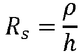
Further, it follows from vector analysis that
τ represents a time constant, m represents electron mass, and E represents electric field. Also,

The following equation applies to N:
For instance, for a zinc spray layer,

The electric field from a charged plate is related to the surface charge.
The typical electric field is measured via

It follows that
In case the material of the core part is just a thermoplastic polymer without any electrically conductive material, and there is no electrically conductive exterior finishing layer either, the following values are applicable.
It follows that
However, when the thermoplastic polymer is provided with a conductive additive, the following is applicable.
It follows that
When it is assumed that an amount of 30 grams of dust is present in the cyclone unit and that an effective area of contact (A) in the cyclone unit is about 0.0225 m2, the following value is found:


Thus, as indicated:


The following result is obtained:
or ≈ 125 nm for 1 µm particles. - It is concluded that sufficient capacity is available when the layer thickness is 0.5 µm and more preferably in a range of 1 to 5 µm. In the wording used earlier, sufficient capacity is available when the material configured to lead electric charges obtained by dirt particles rubbing against the exterior surface away from the exterior surface is present in the core part at least in an exterior layer of a thickness of at least 0.5 µm, more preferably a thickness in a range of 1 to 5 µm.
- When it comes to a choice of material of the core part or the optional exterior finishing layer, it is preferred to use material having a resistivity ρ that is lower than 1010 Ωm, preferably lower than 109 Ωm, and more preferably lower than 108 Ωm.
- In a practical embodiment, the vacuum cleaner unit according to the invention comprises a dirt collection chamber configured to receive and store dirt of the dirt-laden air, wherein the dirt collection chamber is located in the extension of the cleaned air discharge arrangement and the air swirling chamber. Advantages of such a location of the dirt collection chamber include a possibility to have a design of the vacuum cleaner unit that is compact and provides the vacuum cleaner unit with an appealing elongated look, and also a possibility to shape an entrance to the dirt collection chamber in such a way that relatively large particles such as leaves can reach the dirt collection chamber more easily.
- In the case that the vacuum cleaner unit comprises the dirt collection chamber in the way as mentioned, it is possible that the core part of the vacuum cleaner unit includes an extension body extending along the cyclone axis of rotation, in the extension of the cleaned air discharge arrangement and towards the dirt collection chamber. The fact is that such an extension body has a function in dissipating energy from an air flow that is at a position between the cleaned air discharge arrangement and the dirt collection chamber, so that a risk that air at the position of the dirt collection chamber brings about displacement of dirt from the dirt collection chamber is minimized. For reasons of achieving optimal separation performance of the vacuum cleaner unit, it is beneficial if the core part is configured to prevent electrostatic buildup at the position of at least a portion of the exterior surface of the core part located at the extension body. Otherwise, there is a risk that dirt particles stick to the extension body and move over the exterior of the extension body in a direction towards the cleaned air discharge arrangement, similar to a water film moving along a surface, due to the fact that airspeeds close to a surface are relatively low, resulting in low drag forces and centrifugal forces on dirt particles on the surface. In this respect, it is noted that some flow of dirt particles from the dirt collection chamber to the extension body may be expected. Dirt particles moving along the exterior surface of the core part and eventually reaching the gaps in the cleaned air discharge arrangement can enter through the gaps and thereby compromise separation performance of the vacuum cleaner unit.
- It is practical if the cleaned air discharge arrangement is generally tube-shaped, having both a circular interior periphery and a circular exterior periphery. Also, it is practical if the gaps between the vanes of the cleaned air discharge arrangement are generally elongated, extending in a direction of the cyclone axis of rotation. A practical example of an entrance width of the gaps, i.e. an entrance dimension of the gaps in the direction about the cyclone axis of rotation, is an entrance width of about 1 mm. In view of the intended separation performance of the vacuum cleaner unit, it is advantageous if the vanes of the cleaned air discharge arrangement have a generally wing-shaped profile. In the case that the core part includes an extension body, it is further practical if the extension body is generally tube-shaped, having both a circular interior periphery and a circular exterior periphery, wherein it is possible yet not essential if the exterior of the extension body is flush with the exterior of the cleaned air discharge arrangement.
- In general, it is possible that the core part includes a guide part configured to guide incoming dirt-laden air to follow a coil-shaped path towards the cleaned air discharge arrangement. The presence of such a guide part contributes to generating and maintaining the cyclone. For reasons of achieving optimal separation performance of the vacuum cleaner unit, it is beneficial if the core part is configured to prevent electrostatic buildup at the position of at least a portion of the exterior surface of the core part located at the guide part. As explained earlier in respect of the extension body, this measure is meant to avoid a situation in which dirt particles are enabled to pass through the gaps of the cleaned air discharge arrangement from a position on the exterior surface of the core part, which may otherwise happen due to dirt particles sticking to the exterior surface and only experiencing very limited drag forces and centrifugal forces there, which forces are insufficient to detach the dirt particles from the surface.
- In respect of other surfaces located in the vacuum cleaner unit, i.e. surfaces not included in the core part, it is noted that there is no need for those surfaces to have anti-static properties in some way. On the contrary, if those surfaces are prone to attract the dirt, a contribution to effectiveness of the cyclone can be obtained.
- The invention also relates to a vacuum cleaner comprising a conduit, a suction nozzle at an end of the conduit, a vacuum cleaner unit as defined and described in the foregoing, connected to the conduit, and an arrangement configured to generate air suction forces at the position of the suction nozzle and an air flow from the suction nozzle towards the vacuum cleaner unit, through the conduit. The vacuum cleaner may be particularly be of the handheld type, but that does not alter the fact that other types of vacuum cleaner are covered by the invention as well. Generally speaking, the vacuum cleaner according to the invention can be a vacuum cleaner of the canister type, a vacuum cleaner of the stick type, a vacuum cleaner of the upright type, a vacuum cleaner of the robotic type, or a sweeper.
- The above-described and other aspects of the invention will be apparent from and elucidated with reference to the following detailed description of aspects of a vacuum cleaner unit for use in a handheld vacuum cleaner.
- The invention will now be explained in greater detail with reference to the figures, in which equal or similar parts are indicated by the same reference signs, and in which:
-
Figure 1 illustrates a handheld vacuum cleaner including a vacuum cleaner unit according to an embodiment of the invention; -
Figure 2 diagrammatically shows a sectional view of the vacuum cleaner unit; -
Figure 3 diagrammatically shows a front view of the vacuum cleaner unit; -
Figure 4 diagrammatically shows a bottom view of the vacuum cleaner unit and illustrates how air spirals through the vacuum cleaner unit during operation; -
Figure 5 diagrammatically shows a side view of the vacuum cleaner unit and illustrates how air spirals through the vacuum cleaner unit during operation; and -
Figure 6 diagrammatically shows a view on a portion of a section taken along a line A-A infigure 1 . - The invention is in the field of vacuum cleaning and vacuum cleaners, particularly vacuum cleaners comprising a vacuum cleaner unit that is designed to separate dirt and air. A
vacuum cleaner 1 that is of the handheld type and that includes avacuum cleaner unit 2 according to an embodiment of the invention is illustrated infigure 1 . Thevacuum cleaner 1 comprises aconduit 3, asuction nozzle 4 at an end of theconduit 3, thevacuum cleaner unit 2 connected to theconduit 3, and anarrangement 5 configured to generate air suction forces at the position of thesuction nozzle 4 and an air flow from thesuction nozzle 4 towards thevacuum cleaner unit 2, through theconduit 3, whicharrangement 5 normally includes a suitable type of motor. Thehandheld vacuum cleaner 1 may be provided as a removable part of a larger vacuum cleaner such as a stick vacuum cleaner, but it is also possible that thehandheld vacuum cleaner 1 is provided as a standalone device. Normally, a front side of thevacuum cleaner 1 is defined as the side where thesuction nozzle 4 is present and a back side of thevacuum cleaner 1 is defined as the side where thearrangement 5 including the motor is present. Infigure 1 , thevacuum cleaner 1 is shown in a generally horizontal orientation. For the purpose of cleaning floors and other surfaces that can be reached from above, thevacuum cleaner 1 is to be held in a downward orientation, i.e. an orientation with thesuction nozzle 4 pointing downwards, and for the purpose of cleaning ceilings and other surfaces that can be reached from below, thevacuum cleaner 1 is to be held in an upward orientation, i.e. an orientation with thesuction nozzle 4 pointing upwards. - Operating the
handheld vacuum cleaner 1 involves putting thearrangement 5 including the motor to an activated state, so that air suction forces are generated at the position of thesuction nozzle 4. When a person using thevacuum cleaner 1 holds thevacuum cleaner 1 in a position in which thesuction nozzle 4 is close to or on a surface to be cleaned, dirt is removed from the surface under the influence of the air suction forces, wherein the dirt is carried to inside thesuction nozzle 4 and theconduit 3, along with air. The dirt-laden air is made to move towards thevacuum cleaner unit 2 and is supplied to thevacuum cleaner unit 2 at the position of aninlet 6 of thevacuum cleaner unit 2. - As suggested in the foregoing, the
vacuum cleaner unit 2 is designed to separate dirt and air. To that end, thevacuum cleaner unit 2 is equipped with a cleanedair discharge arrangement 10 extending along a cyclone axis of rotation AR, and has an annularair swirling chamber 11 surrounding the cleanedair discharge arrangement 10 in a direction about the cyclone axis of rotation AR. A sectional view of the cleanedair discharge arrangement 10 is separately shown infigure 6 . In the present example, the cleanedair discharge arrangement 10 is generally shaped like a hollow cylinder provided with inwardly protrudingvanes 12 andgaps 13 between thevanes 12, whichgaps 13 are of elongated shape, extending in the direction about the cyclone axis of rotation AR. Thevacuum cleaner unit 2 further has adirt collection chamber 14. The above-mentionedinlet 6 of thevacuum cleaner unit 2 is particularly at a position for letting in dirt-laden air to theair swirling chamber 11. The cleanedair discharge arrangement 10 is configured to discharge air from thevacuum cleaner unit 2, while thedirt collection chamber 14 is configured to receive and store dirt of the dirt-laden air. - During operation of the
vacuum cleaner 1, an air swirling movement about the cleanedair discharge arrangement 10 in theair swirling chamber 11 is promoted on the basis of a number of factors. In the first place, the dirt-laden air is let in tangentially to theair swirling chamber 11 at a side position on thevacuum cleaner unit 2, in the second place, thevacuum cleaner unit 2 is equipped with aguide part 15 that is arranged and shaped such that the incoming air is guided to follow a coil-shaped path, and in the third place, surfaces having a circular outline are generally present in thevacuum cleaner unit 2, as can best be seen infigure 3 . The spiraling movement of the air in thevacuum cleaner unit 2 is illustrated infigures 4 and 5 . As the air swirls about the cleanedair discharge arrangement 10, air passes to inside the cleanedair discharge arrangement 10 through thegaps 13, while the dirt is displaced towards thedirt collection chamber 14 and is collected there. - As can be seen in the
figures 1, 2 ,4 and 5 , thedirt collection chamber 14 is located in the extension of the cleanedair discharge arrangement 10 and theair swirling chamber 11 so that thedirt collection chamber 14 is located further down the cleanedair discharge arrangement 10 and theair swirling chamber 11 in the direction of the cyclone axis of rotation AR. In the present embodiment, thevacuum cleaner unit 2 comprises anextension body 16 extending along the cyclone axis of rotation AR, in the extension of the cleanedair discharge arrangement 10 and towards thedirt collection chamber 14. In the present example, theextension body 16 is generally tube-shaped, having both a circular interior periphery and a circular exterior periphery. Theextension body 16 has a function in ensuring that a minimum of energy is present in the air at the position of thedirt collection chamber 14, so that a risk that dirt in thedirt collection chamber 14 is agitated by the air and thereby displaced from thedirt collection chamber 14 is minimized. - According to the invention, a choice of materials for use in the
vacuum cleaner unit 2 is made in view of a desire to have optimal separation performance of thevacuum cleaner unit 2. In particular, measures are taken so that acore part 17 of thevacuum cleaner unit 2 is configured to prevent electrostatic buildup at the position of at least a portion of anexterior surface 18 of thecore part 17. Basically, thecore part 17 comprises the cleanedair discharge arrangement 10. In the present example, thecore part 17 comprises all three of the cleanedair discharge arrangement 10, theguide part 15 and theextension body 16, i.e. all of the components extending along the cyclone axis of rotation AR at a core position of the cyclone. The measures according to the invention are aimed at avoiding a situation in which dirt particles are drawn towards theexterior surface 18 of thecore part 17 and are made to stick to theexterior surface 18 on the basis of electrostatic forces. The fact is that if such a situation occurs, there is a risk of reduction of the separation performance of thevacuum cleaner unit 2. The reason is that at the very position of theexterior surface 18, forces acting to cause the dirt particles to move away from theexterior surface 18 are generally lower than the electrostatic forces, so that the dirt particles are free to reach thegaps 13 of the cleanedair discharge arrangement 10 from a position on theexterior surface 18. It is an insight of the invention that static electricity can occur because of triboelectric effects following from dirt particles rubbing or sliding against surfaces in thevacuum cleaner unit 2, and that the situation as mentioned can be avoided in a relatively uncomplicated manner, namely by a clever use of materials at appropriate positions in thevacuum cleaner unit 2. It is practical yet not essential if the other surfaces in thevacuum cleaner unit 2, i.e. the surfaces not being theexterior surface 18 of thecore part 17, are configured to attract dirt particles. - The measures of the invention may be realized by using a material in the
core part 17 that is configured to not allow for electric charge transfer from dirt particles rubbing against theexterior surface 18, at least at the position of theexterior surface 18, or by using a material in thecore part 17 that is configured to lead electric charges obtained by dirt particles rubbing against theexterior surface 18 away from theexterior surface 18, at least at the position of theexterior surface 18. In the latter case, it is possible that thecore part 17 comprises an electrically conductive material, at least at the position of theexterior surface 18, or that thecore part 17 is provided with an electrically conductive exterior finishing layer. - Notable aspects of the invention are summarized as follows. In a
vacuum cleaner unit 2 comprising acore part 17 including a cleanedair discharge arrangement 10 and an annularair swirling chamber 11 surrounding the cleanedair discharge arrangement 10, thecore part 17 is configured to prevent electrostatic buildup at the position of at least a portion of anexterior surface 18 of thecore part 17. In this way, beneficial effects to the separation performance of thevacuum cleaner unit 2 are obtained. According to one practical option, thecore part 17 comprises at least at the position of theexterior surface 18 material that is configured to not allow for a triboelectric effect following from dirt particles rubbing or sliding against theexterior surface 18. According to another practical option, electrically conductive material is used in thecore part 17, probably in an exterior finishing layer of thecore part 17, such that electric charges can be led away from theexterior surface 18.
Claims (15)
- Vacuum cleaner unit (2) configured to be used in a vacuum cleaner (1) and to receive incoming dirt-laden air in the vacuum cleaner (1) and to bring about separation of dirt and air, the vacuum cleaner unit (2) comprising:- a core part (17) including a cleaned air discharge arrangement (10) extending along a cyclone axis of rotation (AR), which cleaned air discharge arrangement (10) is configured to discharge air from the vacuum cleaner unit (2);- an annular air swirling chamber (11) surrounding the cleaned air discharge arrangement (10) in a direction about the cyclone axis of rotation (AR); and- at least one inlet (6) configured to let in dirt-laden air to the air swirling chamber (11); wherein the cleaned air discharge arrangement (10) has inwardly protruding vanes (12) and gaps (13) between the vanes (12); andwherein the core part (17) is configured to prevent electrostatic buildup at the position of at least a portion of an exterior surface (18) of the core part (17).
- Vacuum cleaner unit (2) as claimed in claim 1, wherein the core part (17) is configured to prevent electrostatic buildup at the position of at least a portion of the exterior surface (18) of the core part (17) located at the cleaned air discharge arrangement (10).
- Vacuum cleaner unit (2) as claimed in claim 1 or 2, wherein the core part (17) comprises a material configured to not allow for electric charge transfer from dirt particles rubbing against the exterior surface (18), at least at the position of the exterior surface (18).
- Vacuum cleaner unit (2) as claimed in claim 1 or 2, wherein the core part (17) comprises material configured to lead electric charges obtained by dirt particles rubbing against the exterior surface (18) away from the exterior surface (18), at least at the position of the exterior surface (18).
- Vacuum cleaner unit (2) as claimed in claim 4, wherein the core part (17) comprises an electrically conductive material, at least at the position of the exterior surface (18).
- Vacuum cleaner unit (2) as claimed in claim 5, wherein the core part (17) comprises a thermoplastic polymer with an electrically conductive additive.
- Vacuum cleaner unit (2) as claimed in claim 4, wherein the core part (17) is provided with an electrically conductive exterior finishing layer.
- Vacuum cleaner unit (2) as claimed in claim 7, wherein the core part (17) is provided with an exterior finishing layer of a spray paint with an electrically conductive additive.
- Vacuum cleaner unit (2) as claimed in any of claims 4-8, wherein the material configured to lead electric charges obtained by dirt particles rubbing against the exterior surface (18) away from the exterior surface (18) is present in the core part (17) at least in an exterior layer of a thickness of at least 0.5 µm.
- Vacuum cleaner unit (2) as claimed in claim 9, wherein the material configured to lead electric charges obtained by dirt particles rubbing against the exterior surface (18) away from the exterior surface (18) is present in the core part (17) at least in an exterior layer of a thickness in a range of 1 to 5 µm.
- Vacuum cleaner unit (2) as claimed in any of claims 4-10, wherein resistivity (ρ) of the material configured to lead electric charges obtained by dirt particles rubbing against the exterior surface (18) away from the exterior surface (18) is lower than 1010 Ωm, preferably lower than 109 Ωm, and more preferably lower than 108 Ωm.
- Vacuum cleaner unit (2) as claimed in any of claims 1-11, comprising a dirt collection chamber (14) configured to receive and store dirt of the dirt-laden air, wherein the dirt collection chamber (14) is located in the extension of the cleaned air discharge arrangement (10) and the air swirling chamber (11), and wherein the core part (17) includes an extension body (16) extending along the cyclone axis of rotation (AR), in the extension of the cleaned air discharge arrangement (10) and towards the dirt collection chamber (14), and wherein the core part (17) is configured to prevent electrostatic buildup at the position of at least a portion of the exterior surface (18) of the core part (17) located at the extension body (16).
- Vacuum cleaner unit (2) as claimed in any of claims 1-12, wherein the core part (17) includes a guide part (15) configured to guide incoming dirt-laden air to follow a coil-shaped path towards the cleaned air discharge arrangement (10), and wherein the core part (17) is configured to prevent electrostatic buildup at the position of at least a portion of the exterior surface (18) of the core part (17) located at the guide part (15).
- Vacuum cleaner unit (2) as claimed in any of claims 1-13, wherein the vanes (12) of the cleaned air discharge arrangement (10) have a generally wing-shaped profile.
- Vacuum cleaner (1), preferably of the handheld type, comprising a conduit (3), a suction nozzle (4) at an end of the conduit (3), a vacuum cleaner unit (2) as claimed in any of claims 1-14 connected to the conduit (3), and an arrangement (5) configured to generate air suction forces at the position of the suction nozzle (4) and an air flow from the suction nozzle (4) towards the vacuum cleaner unit (2), through the conduit (3).
Priority Applications (3)
| Application Number | Priority Date | Filing Date | Title |
|---|---|---|---|
| EP23191731.1A EP4509025A1 (en) | 2023-08-16 | 2023-08-16 | Preventing electrostatic buildup at a surface of a core part of a vacuum cleaner unit |
| PCT/EP2024/072829 WO2025036909A1 (en) | 2023-08-16 | 2024-08-13 | Preventing electrostatic buildup at a surface of a core part of a vacuum cleaner unit |
| CN202480053498.XA CN121712433A (en) | 2023-08-16 | 2024-08-13 | Preventing static electricity buildup on the surface of the core of the vacuum cleaner unit. |
Applications Claiming Priority (1)
| Application Number | Priority Date | Filing Date | Title |
|---|---|---|---|
| EP23191731.1A EP4509025A1 (en) | 2023-08-16 | 2023-08-16 | Preventing electrostatic buildup at a surface of a core part of a vacuum cleaner unit |
Publications (1)
| Publication Number | Publication Date |
|---|---|
| EP4509025A1 true EP4509025A1 (en) | 2025-02-19 |
Family
ID=87580344
Family Applications (1)
| Application Number | Title | Priority Date | Filing Date |
|---|---|---|---|
| EP23191731.1A Withdrawn EP4509025A1 (en) | 2023-08-16 | 2023-08-16 | Preventing electrostatic buildup at a surface of a core part of a vacuum cleaner unit |
Country Status (3)
| Country | Link |
|---|---|
| EP (1) | EP4509025A1 (en) |
| CN (1) | CN121712433A (en) |
| WO (1) | WO2025036909A1 (en) |
Citations (6)
| Publication number | Priority date | Publication date | Assignee | Title |
|---|---|---|---|---|
| KR20020083019A (en) * | 2001-04-25 | 2002-11-01 | 주식회사 엘지이아이 | device for removing static electricity of cyclone type dust collector |
| EP1371318A2 (en) * | 2002-06-11 | 2003-12-17 | Hitachi Home & Life Solutions, Inc., | Electric vacuum cleaner |
| JP2005007211A (en) * | 2003-06-16 | 2005-01-13 | Mitsubishi Electric Corp | Cyclone dust collector |
| JP5141729B2 (en) * | 2010-07-22 | 2013-02-13 | 三菱電機株式会社 | Electric vacuum cleaner |
| WO2021140041A1 (en) | 2020-01-09 | 2021-07-15 | Koninklijke Philips N.V. | Vortex finder for a cyclonic separator |
| WO2022002591A1 (en) | 2020-06-29 | 2022-01-06 | Koninklijke Philips N.V. | Vacuum cleaner |
-
2023
- 2023-08-16 EP EP23191731.1A patent/EP4509025A1/en not_active Withdrawn
-
2024
- 2024-08-13 CN CN202480053498.XA patent/CN121712433A/en active Pending
- 2024-08-13 WO PCT/EP2024/072829 patent/WO2025036909A1/en active Pending
Patent Citations (6)
| Publication number | Priority date | Publication date | Assignee | Title |
|---|---|---|---|---|
| KR20020083019A (en) * | 2001-04-25 | 2002-11-01 | 주식회사 엘지이아이 | device for removing static electricity of cyclone type dust collector |
| EP1371318A2 (en) * | 2002-06-11 | 2003-12-17 | Hitachi Home & Life Solutions, Inc., | Electric vacuum cleaner |
| JP2005007211A (en) * | 2003-06-16 | 2005-01-13 | Mitsubishi Electric Corp | Cyclone dust collector |
| JP5141729B2 (en) * | 2010-07-22 | 2013-02-13 | 三菱電機株式会社 | Electric vacuum cleaner |
| WO2021140041A1 (en) | 2020-01-09 | 2021-07-15 | Koninklijke Philips N.V. | Vortex finder for a cyclonic separator |
| WO2022002591A1 (en) | 2020-06-29 | 2022-01-06 | Koninklijke Philips N.V. | Vacuum cleaner |
Also Published As
| Publication number | Publication date |
|---|---|
| CN121712433A (en) | 2026-03-20 |
| WO2025036909A1 (en) | 2025-02-20 |
Similar Documents
| Publication | Publication Date | Title |
|---|---|---|
| AU2011278100B2 (en) | A vacuum cleaning appliance | |
| AU2004249066B2 (en) | Dust separator for cyclone type cleaner | |
| US7584522B1 (en) | Vertical cyclonic vacuum assembly | |
| US8465574B2 (en) | Filter | |
| US7749294B2 (en) | Compact robot vacuum cleaner | |
| US8869346B2 (en) | Vacuum cleaner having cyclone dust collecting apparatus | |
| AU2006201525B2 (en) | Cyclone dust collecting device for vacuum cleaner | |
| ES2205917T3 (en) | VACCUM CLEANER. | |
| EP2896341B1 (en) | Suction cleaner | |
| EP2452604B1 (en) | Cyclone dust collecting apparatus and vacuum cleaner having the same | |
| US20080229539A1 (en) | Upright vacuum cleaner using return current of discharging air | |
| US20110016659A1 (en) | Surface treating appliance | |
| KR102013613B1 (en) | Vacuum cleaner | |
| EP3833233B1 (en) | Handheld vacuum cleaner | |
| EP4509025A1 (en) | Preventing electrostatic buildup at a surface of a core part of a vacuum cleaner unit | |
| KR101486860B1 (en) | Cyclone dust collecting apparatus and vacuum cleaner having the same | |
| JP7135405B2 (en) | dust collectors and vacuum cleaners | |
| EP4356804A1 (en) | Vacuum cleaner station | |
| EP4734807A1 (en) | Vacuum cleaner unit including an air swirling space and a dirt space | |
| JP2005160884A (en) | Electric vacuum cleaner | |
| MXPA01006114A (en) | Vacuum cleaner |
Legal Events
| Date | Code | Title | Description |
|---|---|---|---|
| PUAI | Public reference made under article 153(3) epc to a published international application that has entered the european phase |
Free format text: ORIGINAL CODE: 0009012 |
|
| STAA | Information on the status of an ep patent application or granted ep patent |
Free format text: STATUS: THE APPLICATION HAS BEEN PUBLISHED |
|
| AK | Designated contracting states |
Kind code of ref document: A1 Designated state(s): AL AT BE BG CH CY CZ DE DK EE ES FI FR GB GR HR HU IE IS IT LI LT LU LV MC ME MK MT NL NO PL PT RO RS SE SI SK SM TR |
|
| STAA | Information on the status of an ep patent application or granted ep patent |
Free format text: STATUS: THE APPLICATION IS DEEMED TO BE WITHDRAWN |
|
| 18D | Application deemed to be withdrawn |
Effective date: 20250820 |