EP4509014A1 - Slide rail assembly and method for opening slide rail thereof - Google Patents
Slide rail assembly and method for opening slide rail thereof Download PDFInfo
- Publication number
- EP4509014A1 EP4509014A1 EP24170762.9A EP24170762A EP4509014A1 EP 4509014 A1 EP4509014 A1 EP 4509014A1 EP 24170762 A EP24170762 A EP 24170762A EP 4509014 A1 EP4509014 A1 EP 4509014A1
- Authority
- EP
- European Patent Office
- Prior art keywords
- rail
- motor
- electronic module
- driving
- driving member
- Prior art date
- Legal status (The legal status is an assumption and is not a legal conclusion. Google has not performed a legal analysis and makes no representation as to the accuracy of the status listed.)
- Granted
Links
Images





Classifications
-
- A—HUMAN NECESSITIES
- A47—FURNITURE; DOMESTIC ARTICLES OR APPLIANCES; COFFEE MILLS; SPICE MILLS; SUCTION CLEANERS IN GENERAL
- A47B—TABLES; DESKS; OFFICE FURNITURE; CABINETS; DRAWERS; GENERAL DETAILS OF FURNITURE
- A47B88/00—Drawers for tables, cabinets or like furniture; Guides for drawers
- A47B88/40—Sliding drawers; Slides or guides therefor
- A47B88/453—Actuated drawers
- A47B88/46—Actuated drawers operated by mechanically-stored energy, e.g. by springs
- A47B88/463—Actuated drawers operated by mechanically-stored energy, e.g. by springs self-opening
-
- A—HUMAN NECESSITIES
- A47—FURNITURE; DOMESTIC ARTICLES OR APPLIANCES; COFFEE MILLS; SPICE MILLS; SUCTION CLEANERS IN GENERAL
- A47B—TABLES; DESKS; OFFICE FURNITURE; CABINETS; DRAWERS; GENERAL DETAILS OF FURNITURE
- A47B88/00—Drawers for tables, cabinets or like furniture; Guides for drawers
- A47B88/40—Sliding drawers; Slides or guides therefor
- A47B88/453—Actuated drawers
- A47B88/457—Actuated drawers operated by electrically-powered actuation means
-
- A—HUMAN NECESSITIES
- A47—FURNITURE; DOMESTIC ARTICLES OR APPLIANCES; COFFEE MILLS; SPICE MILLS; SUCTION CLEANERS IN GENERAL
- A47B—TABLES; DESKS; OFFICE FURNITURE; CABINETS; DRAWERS; GENERAL DETAILS OF FURNITURE
- A47B88/00—Drawers for tables, cabinets or like furniture; Guides for drawers
- A47B88/40—Sliding drawers; Slides or guides therefor
- A47B88/44—Sequencing or synchronisation of drawer slides or functional units
- A47B88/45—Synchronisation of cooperating drawer slides, i.e. with a coordination of the rail movement of different drawer slides
-
- A—HUMAN NECESSITIES
- A47—FURNITURE; DOMESTIC ARTICLES OR APPLIANCES; COFFEE MILLS; SPICE MILLS; SUCTION CLEANERS IN GENERAL
- A47B—TABLES; DESKS; OFFICE FURNITURE; CABINETS; DRAWERS; GENERAL DETAILS OF FURNITURE
- A47B88/00—Drawers for tables, cabinets or like furniture; Guides for drawers
- A47B88/40—Sliding drawers; Slides or guides therefor
- A47B88/453—Actuated drawers
- A47B88/46—Actuated drawers operated by mechanically-stored energy, e.g. by springs
-
- A—HUMAN NECESSITIES
- A47—FURNITURE; DOMESTIC ARTICLES OR APPLIANCES; COFFEE MILLS; SPICE MILLS; SUCTION CLEANERS IN GENERAL
- A47B—TABLES; DESKS; OFFICE FURNITURE; CABINETS; DRAWERS; GENERAL DETAILS OF FURNITURE
- A47B2210/00—General construction of drawers, guides and guide devices
- A47B2210/0002—Guide construction for drawers
- A47B2210/0051—Guide position
- A47B2210/0056—Guide located at the bottom of the drawer
Definitions
- the present invention is related to a slide rail assembly.
- a drawer In a furniture system, such as a cabinet, a drawer can be opened or closed relative to a cabinet body through a pair of slide rail assemblies.
- a so called push-open product having a drawer capable of being opened from a retracted position relative to a cabinet body by releasing an elastic force of an elastic member (such as a spring) .
- US patent number US 10, 172, 459 B2 discloses a slide rail assembly with the aforementioned push-open function, and a movable rail of the slide rail assembly is arranged with a synchronization device configured to be connected to a synchronization rod for synchronously moving the movable rail with a movable rail of another slide rail assembly.
- patent number WO2021/043756A1 discloses a piece of furniture comprising a furniture carcass and at least one movable furniture part.
- the movable furniture part is movable via a movement fitting between a closed position and an open position.
- a locking device is configured to retain the movable furniture part in the closed position via a permanent magnet on the furniture carcass.
- a triggering device is provided, by means of which the locking device can be disabled, in order to move the movable furniture part in the opening direction.
- the triggering device has an electromagnet, which can be switched via a controller in order to open the movable furniture part from the closed position. As a result, the movable furniture part can be triggered by minor forces.
- a slide rail assembly or a furniture part (such as a drawer or a door panel) is not required to be opened by the aforementioned ways. Therefore, it is important to develop various slide rail products.
- the present invention aims at providing a slide rail assembly and a method for opening a slide rail of a slide rail assembly.
- the claimed slide rail assembly comprises a first rail, a second rail, an elastic member, a movable member and an electronic module.
- the second rail is movable relative to the first rail.
- the elastic member is configured to generate an elastic force in response to the second rail being located at a retracted position relative to the first rail.
- the elastic member is configured to be locked to accumulate the elastic force.
- the electronic module comprises a driving device configured to drive the movable member to switch from the locking state to an unlocking state, in order to release the elastic force of the elastic member, such that the second rail is moved from the retracted position along an opening direction relative to the first rail in response to the elastic force of the elastic member.
- the claimed method for opening a slide rail of a slide rail assembly comprises providing a slide rail assembly comprising a first rail, a second rail and an elastic member; providing a movable member in a locking state arranged on the second rail to lock the elastic member in order to accumulate an elastic force of the elastic member; providing an electronic module arranged on the first rail, wherein the electronic module comprises a driving device; and linking a communication device to the electronic module to control the driving device to drive the movable member to switch to an unlocking state, in order to release the elastic force of the elastic member, such that the second rail is moved away from a retracted position relative to the first rail in response to the elastic force of the elastic member.
- a furniture system 20 comprises a first slide rail assembly 22, a second slide rail assembly 24, a drawer 26 and a cabinet body 28.
- the first slide rail assembly 22 and the second slide rail assembly 24 are configured to mount the drawer 26 to the cabinet body 28, in order to allow the drawer 26 to be movable relative to the cabinet body 28 through the first slide rail assembly 22 and the second slide rail assembly 24.
- each of the first slide rail assembly 22 and the second slide rail assembly 24 have substantially identical structural configuration. More particularly, each of the first slide rail assembly 22 and the second slide rail assembly 24 comprises a first rail 30 and a second rail 32 longitudinally movable relative to the first rail 30. Preferably, each of the first slide rail assembly 22 and the second slide rail assembly 24 further comprises a third rail 34 movably mounted between the first rail 30 and the second rail 32 and configured to extend a moving distance of the second rail 32 relative to the first rail 30.
- the first rail 30 is fixedly mounted on the cabinet body 28, and the second rail 32 is configured to carry the drawer 26.
- the furniture system 20 further comprises a synchronization mechanism 35.
- the synchronization mechanism 35 comprises a first synchronization device 36 and a second synchronization device (not shown in figures due to the viewing angle).
- the first synchronization device 36 and the second synchronization device have substantially identical structural configuration. Furthermore, the first synchronization device 36 is arranged on the second rail 32 of the first slide rail assembly 22, and the second synchronization device is arranged on the second rail 32 of the second slide rail assembly 24, such that the second rail 32 of the first slide rail assembly 22 and the second rail 32 of the second slide rail assembly 24 can be moved synchronously, in order to increase moving stability of the two second rails 32.
- the synchronization mechanism 35 further comprises a synchronization rod 38 detachably mounted between the first synchronization device 36 and the second synchronization device.
- a first end part 38a of the synchronization rod 38 is detachably connected to a first movable member 42 of the first synchronization device 36 through a first connecting base 40a; similarly, a second end part 38b of the synchronization rod 38 is detachably connected to a second movable member (not shown in figures due to the viewing angle) of the second synchronization device through a second connecting base.
- the first rail 30 comprises an extension part 44
- the second rail 32 comprises a carrying part 46.
- the first slide rail assembly 22 is in a retracted state. More particularly, the second rail 32 is located at a retracted position R relative to the first rail 30. When the second rail 32 is located at the retracted position R, the carrying part 46 of the second rail 32 corresponds to the extension part 44 of the first rail 30. For example, the carrying part 46 of the second rail 32 is located above the extension part 44 of the first rail 30.
- the first slide rail assembly 22 further comprises an electronic module 48.
- the electronic module 48 is arranged on the first rail 30.
- the electronic module 48 is detachably mounted on the first rail 30, such that a user can additionally install the electronic module 48 according to requirements.
- the electronic module 48 comprises a base 50 and a cover body 52.
- the base 50 is configured to carry related electronic components or electronic devices.
- the cover body 52 is configured to cover and protect the aforementioned electronic components or electronic devices.
- the electronic module 48 further comprises a driving device 51 configured to work with the first movable member 42.
- the first synchronization device 36 further comprises a first fitting member 53, and the first movable member 42 is detachably mounted to the carrying part 46 of the second rail 32 through the first fitting member 53.
- the carrying part 46 of the second rail 32 comprises at least one first connecting feature 54
- the first fitting member 53 comprises at least one second connecting feature 56.
- the first connecting feature 54 and the second connecting feature 56 respectively are protrusion and slot detachably engaged with each other, but the present invention is not limited thereto.
- the first movable member 42 is rotatably mounted on the second rail 32.
- the first movable member 42 is rotatably mounted on the first fitting member 53 on the carrying part 46 of the second rail 32.
- the electronic module 48 is detachably mounted to a second mounting feature 62 of a side wall 60 of the extension part 44 of the first rail 30 through a first mounting feature 58 of the base 50.
- the first mounting feature 58 and the second mounting feature 62 respectively are extension object and insertion slot detachably engaged with each other, but the present invention is not limited thereto.
- the electronic module 48 further comprises a control circuit board 64 and a position sensor 66.
- the driving device 51 and the position sensor 66 are electrically connected to the control circuit board 64, and the driving device 51 comprises a motor M.
- the motor M is a servo motor.
- the electronic module 48 further comprises a signal transceiver unit and a power supply unit (not shown) .
- the signal transceiver unit is configured to receive and/or transmit wireless signals
- the power supply unit is configured to supply power.
- the first slide rail assembly 22 further comprises an elastic member 68, such as a spring.
- the elastic member 68 is configured to generate an elastic force F along an opening direction D1 in response to the second rail 32 being located at the retracted position R relative to the first rail 30.
- the second rail 32 is configured to be opened relative to the first rail 30 by the elastic force F of the elastic member 68.
- the elastic member 68 can be arranged at a bottom of the carrying part 46 of the second rail 32.
- the elastic member 68 when the second rail 32 is located at the retracted position R relative to the first rail 30 and when the first movable member 42 is in a locking state K1, the elastic member 68 is configured to be locked to accumulate the elastic force F.
- the elastic member 68 when the second rail 32 is located at the retracted position R relative to the first rail 30, the elastic member 68 is configured to be directly locked by the first movable member 42 in order to accumulate the elastic force F; or when the second rail 32 is located at the retracted position R relative to the first rail 30, the elastic member 68 is configured to be locked by a locking member arranged at the bottom of the carrying part 46 of the second rail 32 in order to accumulate the elastic force F, and the first movable member 42 can be further moved to drive the locking member to release the elastic force F of the elastic member 68.
- Such configuration is well known to those skilled in the art, no further illustration is provided for simplification.
- a rotating shaft 69 of the driving device 51 (such as a rotating shaft of the motor M) is arranged with a driving member 70, such as a cam, but the present invention is not limited thereto.
- the rotating shaft 69 is located at an origin position, and the driving member 70 in FIG. 4 is located at an initial position J1 relative to the rotating shaft 69.
- the driving member 70 is adjacent to a working part 71 of the first movable member 42.
- the position sensor 66 is configured to detect whether the second rail 32 is located at the retracted position R relative to the first rail 30.
- the second rail 32 comprises a predetermined part 72, and the predetermined part 72 of the second rail 32 corresponds to the position sensor 66 when the second rail 32 is located at the retracted position R.
- the position sensor 66 can be a contact type or non-contact type sensor to work with the predetermined part 72 of the second rail 32, but the present invention is not limited thereto.
- the first slide rail assembly 22 further comprises a second fitting member 73, and the second fitting member 73 is detachably mounted on the carrying part 46 of the second rail 32.
- the second fitting member 73 comprises the predetermined part 72; or, the predetermined part 72 can be directly integrated into the carrying part 46 of the second rail 32, but the present invention is not limited thereto.
- the driving device 51 is configured to drive the first movable member 42 to switch from the locking state K1 to an unlocking state K2 (as shown in FIG. 5 ), in order to release the elastic force F of the elastic member 68, such that the second rail 32 is moved from the retracted position R (as shown in FIG. 5 ) along the opening direction D1 relative to the first rail 30 in response to the elastic force F of the elastic member 68, to be further moved to a predetermined opening position E (as shown in FIG. 6 ) .
- the predetermined part 72 of the second rail 32 no longer corresponds to the position sensor 66 (the predetermined part 72 of the second rail 32 is away from the position sensor 66) . Therefore, the position sensor 66 can detect that the second rail 32 (the drawer 26) is moved away from the retracted position R.
- the user can operate a communication device 74 to link to the electronic module 48 (as shown in FIG. 5 ), in order to control the motor M of the driving device 51 to drive the first movable member 42 to switch from the locking state K1 to the unlocking state K2, such that the second rail 32 (the drawer 26) is driven to move away from the retracted position R along the opening direction D1 (as shown in FIG. 6 ) relative to the first rail 30 (the cabinet body 28) in response to the elastic force F of the elastic member 68.
- a communication device 74 to link to the electronic module 48 (as shown in FIG. 5 ), in order to control the motor M of the driving device 51 to drive the first movable member 42 to switch from the locking state K1 to the unlocking state K2, such that the second rail 32 (the drawer 26) is driven to move away from the retracted position R along the opening direction D1 (as shown in FIG. 6 ) relative to the first rail 30 (the cabinet body 28) in response to the elastic force F of the elastic member 68.
- the communication device 74 can be a mobile phone, a tablet or a smart wearable device, but the present invention is not limited thereto.
- the driving member 70 is correspondingly moved to the predetermined angle position J2 to contact the working part 71 of the first movable member 42, such that the driving member 70 is configured to drive the first movable member 42 to rotate to switch from the locking state K1 to the unlocking state K2 along a second rotating direction R2, so as to release the elastic force F of the elastic member 68.
- the first rotating direction R1 is opposite to the second rotating direction R2 (as shown in FIG. 5 ) .
- the first rotating direction R1 is the clockwise direction
- the second rotating direction R2 is the counterclockwise direction, but the present invention is not limited thereto.
- the first fitting member 53 of the first synchronization device 36 is arranged with a return elastic component (not shown in figures).
- the first movable member 42 is configured to return to the locking state K1 from the unlocking state K2 (as shown in FIG. 6 ) in response to a return elastic force provided by the return elastic component.
- the position sensor 66 is configured to generate a first signal or a second signal according to the position of the second rail 32 relative to the first rail 30.
- the position sensor 66 is configured to generate the first signal when the second rail 32 (the drawer 26) is located at the retracted position R relative to the first rail 30 (the cabinet body 28) ; and the position sensor 66 is configured to generate the second signal when the second rail 32 (the drawer 26) is moved away from the retracted position R relative to the first rail 30 (the cabinet body 28) .
- the rotating shaft 69 of the driving device 51 is configured to return to the origin position according to the second signal (for indicating that the second rail 32 is moved away from the retracted position R relative to the first rail 30) generated by the position sensor 66, such that the driving member 70 is correspondingly moved back to the initial position J1 (as shown in FIG. 6 ) from the predetermined angle position J2.
- the communication device 74 and the electronic module 48 are wirelessly linkable to each other, but the present invention is not limited thereto.
- the elastic member 68 is configured to be locked to accumulate the elastic force F again.
- FIG. 7 is a flow chart showing operating processes of the furniture system 20 according to the first embodiment of the present invention.
- Step S100 The communication device sets the status of the drawer to open.
- the communication device 74 can be installed with an application (app) to link to the electronic module 48 (the control circuit board 64 of the electronic module 48) for wireless communication.
- the user can transmit a predetermined signal to the electronic module 48 through the application of the communication device 74 (please refer to FIG. 5 ).
- the status of the second rail 32 (the drawer 26) can be set to open.
- the communication device 74 is configured to be linked to the electronic module 48 wirelessly through the application.
- the application can has functions such as voice recognition, Near-Field Communication (NFC) or fingerprint recognition, but the present invention is not limited thereto.
- Step S110 Determine whether the position sensor generates the first signal.
- the control circuit board 64 of the electronic module 48 is configured to determine whether the position sensor 66 generates the first signal (as shown in FIG. 4 ). For example, when the predetermined part 72 of the second rail 32 presses an elastic sensing part 66a of the position sensor 66 (please refer to FIG. 3 ), the position sensor 66 is configured to generate the first signal to the control circuit board 64, to indicate that the second rail 32 (the drawer 26) is currently located at the retracted position R relative to the first rail 30 (the cabinet body 28).
- step S120 The driving device receives a first power signal to rotate the driving member 70 to the predetermined angle position.
- step S120 when the second rail 32 (the drawer 26) is located at the retracted position R relative to the first rail 30 (the cabinet body 28), and when the electronic module 48 receives the predetermined signal from the communication device 74 (as shown in FIG.
- the control circuit board 64 controls the driving device 51 to receive the first power signal, such that the rotating shaft 69 of the motor M of the driving device 51 drives the driving member 70 to rotate to the predetermined angle position J2, in order to further drive the first movable member 42 to switch to the unlocking state K2, so as to release the elastic force F of the elastic member 68.
- step S130 The communication device warns that the drawer is not fully closed.
- the control circuit board 64 is configured to notify the communication device 74 to generate a warning sound and/or an electronic message through the application to let the user know that the second rail 32 (the drawer 26) currently is not located at the retracted position R relative to the first rail 30 (the cabinet body 28).
- step S140 Determine whether the position sensor generates the second signal.
- the control circuit board 64 of the electronic module 48 is configured to determine whether the position sensor 66 generates the second signal (as shown in FIG. 6 ). For example, when the predetermined part 72 of the second rail 32 does not press the elastic sensing part 66a of the position sensor 66, the position sensor 66 is configured to generate the second signal to the control circuit board 64, to indicate that the second rail 32 (the drawer 26) is currently moved away from the retracted position R relative to the first rail 30 (the cabinet body 28) in response to the elastic force F of the elastic member 68. In other words, the second rail 32 (the drawer 26) is moved along the opening direction D1 to the predetermined opening position E.
- step S150 The driving device receives a second power signal to rotate the driving member 70 to the initial position J1.
- the control circuit board 64 controls the driving device 51 to receive the second power signal, such that the rotating shaft 69 of the motor M of the driving device 51 drives the driving member 70 to rotate to the initial position J1 (please refer to FIG. 6 ).
- the position sensor 66 when the position sensor 66 generates the second signal, it means that the second rail 32 (the drawer 26) is currently located at the predetermined opening position E.
- step S160 The communication device generates a system error message for warning.
- the position sensor 66 does not generate the second signal, it means that the second rail 32 (the drawer 26) is not moved away from the retracted position R.
- the control circuit board 64 is configured to notify the communication device 74 to generate a system error message, such as a warning sound and/or an electronic message, through the application to let the user know that the second rail 32 (the drawer 26) currently is not moved away from the retracted position R relative to the first rail 30 (the cabinet body 28).
- FIG. 8 is a flow chart showing a method for opening the second rail 32 relative to the first rail 30 of the slide rail assembly 22 according to the first embodiment of the present invention. The method comprises the following steps:
- FIG. 9 and FIG. 10 are diagrams showing a slide rail assembly, such as a first slide rail assembly 202 of a furniture system according to a second embodiment of the present invention.
- a driving device 204 of the first slide rail assembly 202 has different structural configuration.
- an electronic module 206 of the first slide rail assembly 202 is additionally arranged with a motor origin switch 208 and a motor stop switch 210 electrically connected to a control circuit board 212.
- the driving device 204 comprises a motor M' (as shown in FIG. 10 ).
- the motor M' is a direct current motor, such as a direct current gear motor, but the present invention is not limited thereto.
- a rotating shaft 214 of the motor M' is arranged with a first driving member 216, such as a cam (as shown in FIG. 10 and FIG. 11 ), but the present invention is not limited thereto.
- the first driving member 216 is connected to a second driving member 218.
- the second driving member 218 can be a lever (as shown in FIG. 10 and FIG. 11 ), but the present invention is not limited thereto.
- One of the first driving member 216 and the second driving member 218 is formed with an extension slot 220, and the other one of the first driving member 216 and the second driving member 218 is arranged with a connecting pin 222 extended into the extension slot 220 to work with each other (as shown in FIG. 10 and FIG. 11 ).
- the driving device 204 is configured to drive the first movable member 224 to switch from a locking state K1' (as shown in FUG. 11) to an unlocking state K2' (as shown in FUG. 12), in order to release an elastic force F' of an elastic member 226, such that a second rail 228 is moved from a retracted position R' along the opening direction D1 relative to a first rail 230 in response to the elastic force F' of the elastic member 226.
- the user can operate a communication device 232 to link to the electronic module 206 (as shown in FIG. 9 and FIG. 10 ), in order to control the driving device 204 to drive the first movable member 224 to switch from the locking state K1' (as shown in FIG. 11 ) to the unlocking state K2 (as shown in FIG. 12 ), such that the second rail 228 is driven to move away from the retracted position R' along the opening direction D1 relative to the first rail 230 in response to the elastic force F' of the elastic member 226.
- the second rail 228 is correspondingly moved to a predetermined opening position E' (as shown in FIG. 13 ) .
- the rotating shaft 214 when the rotating shaft 214 is rotated form the origin position to the stop position to drive the first driving member 216 to rotate, the first driving member 216 and the second driving member 218 are rotated in a same direction, for example, the second driving member 218 is rotated form an initial position J1' (as shown in FIG. 11 ) along a first rotating direction R1' to a predetermined angle position J2' (as shown in FIG. 12 ) .
- the second driving member 218 is configured to contact a working part 233 of the first movable member 224 (as shown in FIG. 12 ), such that the first movable member 224 is driven to rotate to switch from the locking K1' (as shown in FIG.
- the second rail 228 is moved from the retracted position R' (as shown in FIG. 9 ) along the opening direction D1 to the predetermined opening position E' (as shown in FIG. 13 ) relative to the first rail 230 in response to the elastic force F' of the elastic member 226.
- the first driving member 216 of the second embodiment is configured to work with the second driving member 218 (such as a lever) in order to increase moment arm, such that the motor M' of the driving device 204 is required to output a smaller force from the rotating shaft 214 for driving the first movable member 224, so as to save power consumption of the driving device 204.
- the second driving member 218 such as a lever
- the motor origin switch 208 and the motor stop switch 210 are configured to detect positions of the motor M' .
- the motor origin switch 208 is configured to generate a third signal and a fourth signal.
- the second driving member 218 is located at the initial position J1' relative to the rotating shaft 214, and the motor origin switch 208 is configured to generate the third signal; when the rotating shaft 214 of the motor M' is moved away from the origin position, the motor origin switch 208 is configured to generate the fourth signal.
- the motor stop switch 210 is configured to generate a fifth signal and a sixth signal.
- the motor stop switch 210 When the rotating shaft 214 of the motor M' is located at the stop position, the second driving member 218 is located at the predetermined angle position J2' relative to the rotating shaft 214, and the motor stop switch 210 is configured to generate the fifth signal; when the rotating shaft 214 of the motor M' is moved away from the stop position, the motor stop switch 210 is configured to generate the sixth signal.
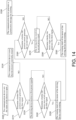
- FIG. 14 is a flow chart showing operating process of the furniture system according to the second embodiment of the present invention.
- the operating process comprises the following steps: Step S200: The communication device sets the status of the drawer to open.
- the communication device 232 can be installed with an application to link to the electronic module 206 (the control circuit board 212 of the electronic module 206) for wireless communication.
- the user can transmit a predetermined signal to the electronic module 206 through the communication device 232.
- the status of the second rail 228 (the drawer) can be set to open.
- Step S210 Determine whether the position sensor generates the first signal.
- the control circuit board 212 of the electronic module 206 is configured to determine whether the position sensor 234 generates the first signal (as shown in FIG. 9 ) . For example, when a predetermined part 236 of the second rail 228 presses an elastic sensing part 234a of the position sensor 234, the position sensor 234 is configured to generate the first signal to the control circuit board 212, to indicate that the second rail 228 (the drawer) is currently located at the retracted position R' relative to the first rail 230 (the cabinet body).
- step S220 The driving device receives a first power signal.
- the control circuit board 212 controls the driving device 204 to receive a first power signal, such that the rotating shaft 214 of the motor M' of the driving device 204 is rotated to the stop position to drive the second driving member 218 to rotate to the predetermined angle position J2' (as shown in FIG. 12 ), in order to further drive the first movable member 224 to switch to the unlocking state K2' (as shown in FIG. 12 ), so as to release the elastic force F' of the elastic member 226.
- step S230 The communication device warns that the drawer is not fully closed.
- the control circuit board 212 is configured to notify the communication device 232 to generate a warning sound and/or an electronic message through the application to let the user know that the second rail 228 (the drawer) currently is not located at the retracted position R' relative to the first rail 230 (the cabinet body).
- step S240 Determine whether the motor stop switch generates the fifth signal.
- the control circuit board 212 of the electronic module 206 is configured to determine whether the motor stop switch 210 generates the fifth signal, in order to determine whether the rotating shaft 214 of the motor M' of the driving device 204 is located at the stop position (or whether the second driving member 218 is located at the predetermined angle position J2') as shown in FIG. 12 .
- step S250 The rotating shaft of the motor of the driving device stops rotating.
- the rotating shaft 214 of the motor M' of the driving device 204 stops at the stop position (the second driving member 218 stops at the predetermined angle position J2' as shown in FIG. 12 ). If the control circuit board 212 of the electronic module 206 determines that the motor stop switch 210 does not generate the fifth signal, then return to step S220.
- step S260 Determine whether the position sensor generates the second signal.
- the control circuit board 212 of the electronic module 206 is configured to determine whether the position sensor 234 generates the second signal (as shown in FIG. 13 ). For example, when the predetermined part 236 of the second rail 228 does not press the elastic sensing part 234a of the position sensor 234, the position sensor 234 is configured to generate the second signal to the control circuit board 212, to indicate that the second rail 228 (the drawer) is currently moved away from the retracted position R' (or located at the predetermined opening position E') relative to the first rail 230 (the cabinet body) in response to the elastic F' of the elastic member 226.
- step S270 The driving device receives a second power signal.
- the control circuit board 212 controls the driving device 204 to receive the second power signal, such that the rotating shaft 214 of the motor M' of the driving device 204 is rotated back to the origin position, in order to drive the second driving member 218 to correspondingly rotate to the initial position J1' (please refer to FIG. 11 ).
- step S280 The communication device generates a system error message for warning.
- the position sensor 234 does not generate the second signal, it means that the second rail 228 (the drawer) is not moved away from the retracted position R'.
- the control circuit board 212 is configured to notify the communication device 232 to generate a system error message, such as a warning sound and/or an electronic message, through the application to let the user know that the second rail 228 (the drawer) currently is not moved away from the retracted position R'.
- step S290 Determine whether the motor origin switch generates the third signal.
- the control circuit board 212 of the electronic module 206 is configured to determine whether the motor origin switch 208 generates the third signal, in order to further determine whether the rotating shaft 214 of the motor M' of the driving device 204 is located at the origin position (or whether the second driving member 218 is located at the initial position J1') as shown in FIG. 11 .
- step S292 The rotating shaft of the motor of the driving device stops rotating.
- the control circuit board 212 of the electronic module 206 determines that the motor origin switch 208 generates the third signal
- the rotating shaft 214 of the motor M' of the driving device 204 stops at the origin position
- the second driving member 218 correspondingly stops at the initial position J1' (as shown in FIG. 11 ). Meanwhile, it means that the drawer has been opened.
- the position sensor 234 generates the second signal and the motor origin switch 208 generates the third signal, it means that the furniture system has completed the operation of opening the second rail 228 (drawer). If the control circuit board 212 of the electronic module 206 determines that the motor origin switch 208 does not generate the third signal, then return to step S270.
- the slide rail assembly according to the embodiments of the present invention has the following technical features:
Landscapes
- Engineering & Computer Science (AREA)
- Mechanical Engineering (AREA)
- Drawers Of Furniture (AREA)
Abstract
Description
- The present invention is related to a slide rail assembly.
- In a furniture system, such as a cabinet, a drawer can be opened or closed relative to a cabinet body through a pair of slide rail assemblies. Currently, there is a so called push-open product having a drawer capable of being opened from a retracted position relative to a cabinet body by releasing an elastic force of an elastic member (such as a spring) . US patent number
US 10, 172, 459 B2 - In addition, patent number
WO2021/043756A1 discloses a piece of furniture comprising a furniture carcass and at least one movable furniture part. The movable furniture part is movable via a movement fitting between a closed position and an open position. A locking device is configured to retain the movable furniture part in the closed position via a permanent magnet on the furniture carcass. A triggering device is provided, by means of which the locking device can be disabled, in order to move the movable furniture part in the opening direction. The triggering device has an electromagnet, which can be switched via a controller in order to open the movable furniture part from the closed position. As a result, the movable furniture part can be triggered by minor forces. - For different market requirements, sometimes a slide rail assembly or a furniture part (such as a drawer or a door panel) is not required to be opened by the aforementioned ways. Therefore, it is important to develop various slide rail products.
- This in mind, the present invention aims at providing a slide rail assembly and a method for opening a slide rail of a slide rail assembly.
- This is achieved by a slide rail assembly according to claim 1, and a method for opening a slide rail of a slide rail assembly according to claim 10. The dependent claims pertain to corresponding further developments and improvements.
- As will be seen more clearly from the detailed description following below, the claimed slide rail assembly comprises a first rail, a second rail, an elastic member, a movable member and an electronic module. The second rail is movable relative to the first rail. The elastic member is configured to generate an elastic force in response to the second rail being located at a retracted position relative to the first rail. When the second rail is located at the retracted position relative to the first rail and when the movable member is in a locking state, the elastic member is configured to be locked to accumulate the elastic force. The electronic module comprises a driving device configured to drive the movable member to switch from the locking state to an unlocking state, in order to release the elastic force of the elastic member, such that the second rail is moved from the retracted position along an opening direction relative to the first rail in response to the elastic force of the elastic member.
- As will be seen more clearly from the detailed description following below, the claimed method for opening a slide rail of a slide rail assembly comprises providing a slide rail assembly comprising a first rail, a second rail and an elastic member; providing a movable member in a locking state arranged on the second rail to lock the elastic member in order to accumulate an elastic force of the elastic member; providing an electronic module arranged on the first rail, wherein the electronic module comprises a driving device; and linking a communication device to the electronic module to control the driving device to drive the movable member to switch to an unlocking state, in order to release the elastic force of the elastic member, such that the second rail is moved away from a retracted position relative to the first rail in response to the elastic force of the elastic member.
- In the following, the invention is further illustrated by way of example, taking reference to the accompanying drawings thereof:
-
FIG. 1 is a diagram showing a furniture system comprising at least one drawer and a cabinet body according to a first embodiment of the present invention; -
FIG. 2 is a diagram showing the furniture system comprising a synchronization device arranged between two slide rail assemblies on the cabinet body according to the first embodiment of the present invention; -
FIG. 3 is an exploded view of the slide rail assembly and an electronic module according to the first embodiment of the present invention; -
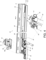
FIG. 4 is a diagram showing a second rail located at a retracted position relative to a first rail of the slide rail assembly according to the first embodiment of the present invention; -
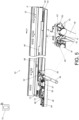
FIG. 5 is a diagram showing the second rail located at the retracted position relative to the first rail of the slide rail assembly and a user trying to operate a communication device to control the electronic module to move the second rail away from the retracted position according to the first embodiment of the present invention; -
FIG. 6 is a diagram showing the second rail being moved from the retracted position to a predetermined open position relative to the first rail of the slide rail assembly according to the first embodiment of the present invention; -
FIG. 7 is a flow chart showing operating processes of the furniture system according to the first embodiment of the present invention; -
FIG. 8 is a flow chart showing a method for opening the second rail of the slide rail assembly according to the first embodiment of the present invention; -
FIG. 9 is a diagram showing a second rail located at a retracted position relative to a first rail of a slide rail assembly according to a second embodiment of the present invention; -
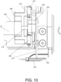
FIG. 10 is an enlarged view of an area A ofFIG. 9 ; -
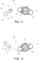
FIG. 11 is a diagram showing at least one driving member of a driving device and a movable member of a synchronization device according to the second embodiment of the present invention; -
FIG. 12 is a diagram showing the at least one driving member of the driving device driving the movable member of the synchronization device to move according to the second embodiment of the present invention; -
FIG. 13 is a diagram showing the second rail being moved from the retracted position to a predetermined open position relative to the first rail of the slide rail assembly according to the second embodiment of the present invention; and -
FIG. 14 is a flow chart showing operating processes of a furniture system according to the second embodiment of the present invention. - As shown in
FIG. 1 andFIG. 2 , afurniture system 20 comprises a firstslide rail assembly 22, a second slide rail assembly 24, adrawer 26 and acabinet body 28. The firstslide rail assembly 22 and the second slide rail assembly 24 are configured to mount thedrawer 26 to thecabinet body 28, in order to allow thedrawer 26 to be movable relative to thecabinet body 28 through the firstslide rail assembly 22 and the second slide rail assembly 24. - The first
slide rail assembly 22 and the second slide rail assembly 24 have substantially identical structural configuration. More particularly, each of the firstslide rail assembly 22 and the second slide rail assembly 24 comprises afirst rail 30 and asecond rail 32 longitudinally movable relative to thefirst rail 30. Preferably, each of the firstslide rail assembly 22 and the second slide rail assembly 24 further comprises athird rail 34 movably mounted between thefirst rail 30 and thesecond rail 32 and configured to extend a moving distance of thesecond rail 32 relative to thefirst rail 30. Thefirst rail 30 is fixedly mounted on thecabinet body 28, and thesecond rail 32 is configured to carry thedrawer 26. Thefurniture system 20 further comprises asynchronization mechanism 35. Thesynchronization mechanism 35 comprises afirst synchronization device 36 and a second synchronization device (not shown in figures due to the viewing angle). Thefirst synchronization device 36 and the second synchronization device have substantially identical structural configuration. Furthermore, thefirst synchronization device 36 is arranged on thesecond rail 32 of the firstslide rail assembly 22, and the second synchronization device is arranged on thesecond rail 32 of the second slide rail assembly 24, such that thesecond rail 32 of the firstslide rail assembly 22 and thesecond rail 32 of the second slide rail assembly 24 can be moved synchronously, in order to increase moving stability of the twosecond rails 32. Thesynchronization mechanism 35 further comprises asynchronization rod 38 detachably mounted between thefirst synchronization device 36 and the second synchronization device. Afirst end part 38a of thesynchronization rod 38 is detachably connected to a firstmovable member 42 of thefirst synchronization device 36 through a first connectingbase 40a; similarly, asecond end part 38b of thesynchronization rod 38 is detachably connected to a second movable member (not shown in figures due to the viewing angle) of the second synchronization device through a second connecting base. - Preferably, the
first rail 30 comprises anextension part 44, and thesecond rail 32 comprises acarrying part 46. - As shown in
FIG. 3 , the firstslide rail assembly 22 is in a retracted state. More particularly, thesecond rail 32 is located at a retracted position R relative to thefirst rail 30. When thesecond rail 32 is located at the retracted position R, the carryingpart 46 of thesecond rail 32 corresponds to theextension part 44 of thefirst rail 30. For example, the carryingpart 46 of thesecond rail 32 is located above theextension part 44 of thefirst rail 30. - The first
slide rail assembly 22 further comprises anelectronic module 48. Preferably, theelectronic module 48 is arranged on thefirst rail 30. In the present embodiment, theelectronic module 48 is detachably mounted on thefirst rail 30, such that a user can additionally install theelectronic module 48 according to requirements. Preferably, theelectronic module 48 comprises abase 50 and acover body 52. Thebase 50 is configured to carry related electronic components or electronic devices. Thecover body 52 is configured to cover and protect the aforementioned electronic components or electronic devices. - The
electronic module 48 further comprises adriving device 51 configured to work with the firstmovable member 42. - Preferably, the
first synchronization device 36 further comprises a firstfitting member 53, and the firstmovable member 42 is detachably mounted to the carryingpart 46 of thesecond rail 32 through the firstfitting member 53. For example, the carryingpart 46 of thesecond rail 32 comprises at least one first connectingfeature 54, and the firstfitting member 53 comprises at least one second connectingfeature 56. In the present embodiment, the first connectingfeature 54 and the second connectingfeature 56 respectively are protrusion and slot detachably engaged with each other, but the present invention is not limited thereto. - Preferably, the first
movable member 42 is rotatably mounted on thesecond rail 32. In the present embodiment, the firstmovable member 42 is rotatably mounted on the firstfitting member 53 on the carryingpart 46 of thesecond rail 32. - Preferably, the
electronic module 48 is detachably mounted to asecond mounting feature 62 of aside wall 60 of theextension part 44 of thefirst rail 30 through a first mountingfeature 58 of thebase 50. In the present embodiment, the first mountingfeature 58 and the second mountingfeature 62 respectively are extension object and insertion slot detachably engaged with each other, but the present invention is not limited thereto. - Preferably, the
electronic module 48 further comprises acontrol circuit board 64 and aposition sensor 66. The drivingdevice 51 and theposition sensor 66 are electrically connected to thecontrol circuit board 64, and the drivingdevice 51 comprises a motor M. In the first embodiment, the motor M is a servo motor. - Preferably, the
electronic module 48 further comprises a signal transceiver unit and a power supply unit (not shown) . The signal transceiver unit is configured to receive and/or transmit wireless signals, and the power supply unit is configured to supply power. - As shown in
FIG. 4 (the first connectingbase 40a and thecover body 52 of theelectronic module 48 are omitted inFIG. 4 ), the firstslide rail assembly 22 further comprises anelastic member 68, such as a spring. Theelastic member 68 is configured to generate an elastic force F along an opening direction D1 in response to thesecond rail 32 being located at the retracted position R relative to thefirst rail 30. Thesecond rail 32 is configured to be opened relative to thefirst rail 30 by the elastic force F of theelastic member 68. In other words, the second rail 32 (the drawer 26) can be ejected to be opened relative to the first rail 30 (the cabinet body 28). Preferably, theelastic member 68 can be arranged at a bottom of the carryingpart 46 of thesecond rail 32. - Moreover, when the
second rail 32 is located at the retracted position R relative to thefirst rail 30 and when the firstmovable member 42 is in a locking state K1, theelastic member 68 is configured to be locked to accumulate the elastic force F. For example, when thesecond rail 32 is located at the retracted position R relative to thefirst rail 30, theelastic member 68 is configured to be directly locked by the firstmovable member 42 in order to accumulate the elastic force F; or when thesecond rail 32 is located at the retracted position R relative to thefirst rail 30, theelastic member 68 is configured to be locked by a locking member arranged at the bottom of the carryingpart 46 of thesecond rail 32 in order to accumulate the elastic force F, and the firstmovable member 42 can be further moved to drive the locking member to release the elastic force F of theelastic member 68. Such configuration is well known to those skilled in the art, no further illustration is provided for simplification. - In addition, in the first embodiment, a rotating
shaft 69 of the driving device 51 (such as a rotating shaft of the motor M) is arranged with a drivingmember 70, such as a cam, but the present invention is not limited thereto. Furthermore, when thesecond rail 32 is located at the retracted position R relative to thefirst rail 30, the rotatingshaft 69 is located at an origin position, and the drivingmember 70 inFIG. 4 is located at an initial position J1 relative to therotating shaft 69. When the firstmovable member 42 is in the locking state K1 and when the drivingmember 70 is located at the initial position J1, the drivingmember 70 is adjacent to a workingpart 71 of the firstmovable member 42. - Preferably, the
position sensor 66 is configured to detect whether thesecond rail 32 is located at the retracted position R relative to thefirst rail 30. For example, thesecond rail 32 comprises apredetermined part 72, and thepredetermined part 72 of thesecond rail 32 corresponds to theposition sensor 66 when thesecond rail 32 is located at the retracted position R. Theposition sensor 66 can be a contact type or non-contact type sensor to work with thepredetermined part 72 of thesecond rail 32, but the present invention is not limited thereto. - Preferably, the first
slide rail assembly 22 further comprises a secondfitting member 73, and the secondfitting member 73 is detachably mounted on the carryingpart 46 of thesecond rail 32. The secondfitting member 73 comprises thepredetermined part 72; or, thepredetermined part 72 can be directly integrated into the carryingpart 46 of thesecond rail 32, but the present invention is not limited thereto. - As shown in
FIG. 5 andFIG. 6 , the drivingdevice 51 is configured to drive the firstmovable member 42 to switch from the locking state K1 to an unlocking state K2 (as shown inFIG. 5 ), in order to release the elastic force F of theelastic member 68, such that thesecond rail 32 is moved from the retracted position R (as shown inFIG. 5 ) along the opening direction D1 relative to thefirst rail 30 in response to the elastic force F of theelastic member 68, to be further moved to a predetermined opening position E (as shown inFIG. 6 ) . As such, thepredetermined part 72 of thesecond rail 32 no longer corresponds to the position sensor 66 (thepredetermined part 72 of thesecond rail 32 is away from the position sensor 66) . Therefore, theposition sensor 66 can detect that the second rail 32 (the drawer 26) is moved away from the retracted position R. - Furthermore, the user can operate a
communication device 74 to link to the electronic module 48 (as shown inFIG. 5 ), in order to control the motor M of the drivingdevice 51 to drive the firstmovable member 42 to switch from the locking state K1 to the unlocking state K2, such that the second rail 32 (the drawer 26) is driven to move away from the retracted position R along the opening direction D1 (as shown inFIG. 6 ) relative to the first rail 30 (the cabinet body 28) in response to the elastic force F of theelastic member 68. - Preferably, the
communication device 74 can be a mobile phone, a tablet or a smart wearable device, but the present invention is not limited thereto. - Preferably, through the rotating
shaft 69 of the motor M driving the drivingmember 70 to rotate from the initial position J1 to a predetermined angle position J2 along a first rotating direction R1, the drivingmember 70 is correspondingly moved to the predetermined angle position J2 to contact the workingpart 71 of the firstmovable member 42, such that the drivingmember 70 is configured to drive the firstmovable member 42 to rotate to switch from the locking state K1 to the unlocking state K2 along a second rotating direction R2, so as to release the elastic force F of theelastic member 68. The first rotating direction R1 is opposite to the second rotating direction R2 (as shown inFIG. 5 ) . For example, the first rotating direction R1 is the clockwise direction, the second rotating direction R2 is the counterclockwise direction, but the present invention is not limited thereto. - Preferably, the first
fitting member 53 of thefirst synchronization device 36 is arranged with a return elastic component (not shown in figures). When thesecond rail 32 is located at the predetermined opening position E relative to the first rail 30 (as shown inFIG. 6 ), the firstmovable member 42 is configured to return to the locking state K1 from the unlocking state K2 (as shown inFIG. 6 ) in response to a return elastic force provided by the return elastic component. On the other hand, theposition sensor 66 is configured to generate a first signal or a second signal according to the position of thesecond rail 32 relative to thefirst rail 30. For example, theposition sensor 66 is configured to generate the first signal when the second rail 32 (the drawer 26) is located at the retracted position R relative to the first rail 30 (the cabinet body 28) ; and theposition sensor 66 is configured to generate the second signal when the second rail 32 (the drawer 26) is moved away from the retracted position R relative to the first rail 30 (the cabinet body 28) . The rotatingshaft 69 of the drivingdevice 51 is configured to return to the origin position according to the second signal (for indicating that thesecond rail 32 is moved away from the retracted position R relative to the first rail 30) generated by theposition sensor 66, such that the drivingmember 70 is correspondingly moved back to the initial position J1 (as shown inFIG. 6 ) from the predetermined angle position J2. - Preferably, the
communication device 74 and theelectronic module 48 are wirelessly linkable to each other, but the present invention is not limited thereto. - More particularly, when the second rail 32 (the drawer 26) is moved from the predetermined opening position E along a retracting direction D2 (as shown in
FIG. 6 ) relative to the first rail 30 (the cabinet body 28) to return to the retracted position R, theelastic member 68 is configured to be locked to accumulate the elastic force F again. Such configuration is well known to those skilled in the art, no further illustration is provided for simplification. -
FIG. 7 is a flow chart showing operating processes of thefurniture system 20 according to the first embodiment of the present invention. - Step S100: The communication device sets the status of the drawer to open.
- In the step S100, the
communication device 74 can be installed with an application (app) to link to the electronic module 48 (thecontrol circuit board 64 of the electronic module 48) for wireless communication. The user can transmit a predetermined signal to theelectronic module 48 through the application of the communication device 74 (please refer toFIG. 5 ). As such, the status of the second rail 32 (the drawer 26) can be set to open. In the present embodiment, thecommunication device 74 is configured to be linked to theelectronic module 48 wirelessly through the application. The application can has functions such as voice recognition, Near-Field Communication (NFC) or fingerprint recognition, but the present invention is not limited thereto. - Step S110: Determine whether the position sensor generates the first signal.
- In the step S110, the
control circuit board 64 of theelectronic module 48 is configured to determine whether theposition sensor 66 generates the first signal (as shown inFIG. 4 ). For example, when thepredetermined part 72 of thesecond rail 32 presses anelastic sensing part 66a of the position sensor 66 (please refer toFIG. 3 ), theposition sensor 66 is configured to generate the first signal to thecontrol circuit board 64, to indicate that the second rail 32 (the drawer 26) is currently located at the retracted position R relative to the first rail 30 (the cabinet body 28). - If the
control circuit board 64 of theelectronic module 48 determines that theposition sensor 66 generates the first signal, then go to step S120: The driving device receives a first power signal to rotate the drivingmember 70 to the predetermined angle position. In the step S120, when the second rail 32 (the drawer 26) is located at the retracted position R relative to the first rail 30 (the cabinet body 28), and when theelectronic module 48 receives the predetermined signal from the communication device 74 (as shown inFIG. 5 ), thecontrol circuit board 64 controls the drivingdevice 51 to receive the first power signal, such that the rotatingshaft 69 of the motor M of the drivingdevice 51 drives the drivingmember 70 to rotate to the predetermined angle position J2, in order to further drive the firstmovable member 42 to switch to the unlocking state K2, so as to release the elastic force F of theelastic member 68. - If the
control circuit board 64 of theelectronic module 48 determines that theposition sensor 66 does not generate the first signal, then go to step S130: The communication device warns that the drawer is not fully closed. In the step S130, if theposition sensor 66 does not generate the first signal, thecontrol circuit board 64 is configured to notify thecommunication device 74 to generate a warning sound and/or an electronic message through the application to let the user know that the second rail 32 (the drawer 26) currently is not located at the retracted position R relative to the first rail 30 (the cabinet body 28). - After the step S120, go to step S140: Determine whether the position sensor generates the second signal. In the step S140, the
control circuit board 64 of theelectronic module 48 is configured to determine whether theposition sensor 66 generates the second signal (as shown inFIG. 6 ). For example, when thepredetermined part 72 of thesecond rail 32 does not press theelastic sensing part 66a of theposition sensor 66, theposition sensor 66 is configured to generate the second signal to thecontrol circuit board 64, to indicate that the second rail 32 (the drawer 26) is currently moved away from the retracted position R relative to the first rail 30 (the cabinet body 28) in response to the elastic force F of theelastic member 68. In other words, the second rail 32 (the drawer 26) is moved along the opening direction D1 to the predetermined opening position E. - If the
control circuit board 64 of theelectronic module 48 determines that theposition sensor 66 generates the second signal, then go to step S150: The driving device receives a second power signal to rotate the drivingmember 70 to the initial position J1. In the step S150, when theposition sensor 66 generates the second signal, thecontrol circuit board 64 controls the drivingdevice 51 to receive the second power signal, such that the rotatingshaft 69 of the motor M of the drivingdevice 51 drives the drivingmember 70 to rotate to the initial position J1 (please refer toFIG. 6 ). In other words, when theposition sensor 66 generates the second signal, it means that the second rail 32 (the drawer 26) is currently located at the predetermined opening position E. - If the
control circuit board 64 of theelectronic module 48 determines that theposition sensor 66 does not generate the second signal, then go to step S160: The communication device generates a system error message for warning. In the step S160, if theposition sensor 66 does not generate the second signal, it means that the second rail 32 (the drawer 26) is not moved away from the retracted position R. Thecontrol circuit board 64 is configured to notify thecommunication device 74 to generate a system error message, such as a warning sound and/or an electronic message, through the application to let the user know that the second rail 32 (the drawer 26) currently is not moved away from the retracted position R relative to the first rail 30 (the cabinet body 28). -
FIG. 8 is a flow chart showing a method for opening thesecond rail 32 relative to thefirst rail 30 of theslide rail assembly 22 according to the first embodiment of the present invention. The method comprises the following steps: - Step S10: Provide a
slide rail assembly 22 comprising afirst rail 30, asecond rail 32 and an elastic member 68 (please refer toFIG. 4 ). - Step S12: Provide a
movable member 42 in a locking state K1 arranged on thesecond rail 32 to lock theelastic member 68 in order to accumulate an elastic force F of the elastic member 68 (please refer toFIG. 4 ). - Step S14 : Provide an
electronic module 48 arranged on thefirst rail 30, wherein theelectronic module 48 comprises a driving device 51 (please refer toFIG. 4 ). - Step S16: Link a
communication device 74 to theelectronic module 48 to control the drivingdevice 51 to drive themovable member 42 to switch to an unlocking state K2 (please refer toFIG. 5 ), in order to release the elastic force F of theelastic member 68, such that thesecond rail 32 is moved away from a retracted position R relative to thefirst rail 30 in response to the elastic force F of the elastic member 68 (please refer toFIG. 5 andFIG. 6 ) . - Details of the method have been disclosed above, no further illustration is provided for simplification.
-
FIG. 9 andFIG. 10 are diagrams showing a slide rail assembly, such as a firstslide rail assembly 202 of a furniture system according to a second embodiment of the present invention. In contrast to the firstslide rail assembly 22 of the first embodiment, adriving device 204 of the firstslide rail assembly 202 has different structural configuration. In addition, anelectronic module 206 of the firstslide rail assembly 202 is additionally arranged with amotor origin switch 208 and amotor stop switch 210 electrically connected to acontrol circuit board 212. - As shown in
FIG. 9 to FIG. 13 , the drivingdevice 204 comprises a motor M' (as shown inFIG. 10 ). In the second embodiment, the motor M' is a direct current motor, such as a direct current gear motor, but the present invention is not limited thereto. Arotating shaft 214 of the motor M' is arranged with afirst driving member 216, such as a cam (as shown inFIG. 10 andFIG. 11 ), but the present invention is not limited thereto. Thefirst driving member 216 is connected to asecond driving member 218. Thesecond driving member 218 can be a lever (as shown inFIG. 10 andFIG. 11 ), but the present invention is not limited thereto. One of the first drivingmember 216 and thesecond driving member 218 is formed with anextension slot 220, and the other one of the first drivingmember 216 and thesecond driving member 218 is arranged with a connectingpin 222 extended into theextension slot 220 to work with each other (as shown inFIG. 10 andFIG. 11 ). - The
driving device 204 is configured to drive the firstmovable member 224 to switch from a locking state K1' (as shown in FUG. 11) to an unlocking state K2' (as shown in FUG. 12), in order to release an elastic force F' of anelastic member 226, such that asecond rail 228 is moved from a retracted position R' along the opening direction D1 relative to afirst rail 230 in response to the elastic force F' of theelastic member 226. - Furthermore, the user can operate a
communication device 232 to link to the electronic module 206 (as shown inFIG. 9 andFIG. 10 ), in order to control thedriving device 204 to drive the firstmovable member 224 to switch from the locking state K1' (as shown inFIG. 11 ) to the unlocking state K2 (as shown inFIG. 12 ), such that thesecond rail 228 is driven to move away from the retracted position R' along the opening direction D1 relative to thefirst rail 230 in response to the elastic force F' of theelastic member 226. For example, thesecond rail 228 is correspondingly moved to a predetermined opening position E' (as shown inFIG. 13 ) . More particularly, when therotating shaft 214 is rotated form the origin position to the stop position to drive the first drivingmember 216 to rotate, the first drivingmember 216 and thesecond driving member 218 are rotated in a same direction, for example, thesecond driving member 218 is rotated form an initial position J1' (as shown inFIG. 11 ) along a first rotating direction R1' to a predetermined angle position J2' (as shown inFIG. 12 ) . During such rotating process, thesecond driving member 218 is configured to contact a workingpart 233 of the first movable member 224 (as shown inFIG. 12 ), such that the firstmovable member 224 is driven to rotate to switch from the locking K1' (as shown inFIG. 11 ) to the unlocking state K2' (as shown inFIG. 12 ) through thesecond driving member 218, in order to release the elastic force F' of theelastic member 226. As such, thesecond rail 228 is moved from the retracted position R' (as shown inFIG. 9 ) along the opening direction D1 to the predetermined opening position E' (as shown inFIG. 13 ) relative to thefirst rail 230 in response to the elastic force F' of theelastic member 226. In contrast to the first embodiment, the first drivingmember 216 of the second embodiment is configured to work with the second driving member 218 (such as a lever) in order to increase moment arm, such that the motor M' of thedriving device 204 is required to output a smaller force from therotating shaft 214 for driving the firstmovable member 224, so as to save power consumption of thedriving device 204. - Moreover, the
motor origin switch 208 and themotor stop switch 210 are configured to detect positions of the motor M' . For example, themotor origin switch 208 is configured to generate a third signal and a fourth signal. When therotating shaft 214 of the motor M' is located at the origin position, thesecond driving member 218 is located at the initial position J1' relative to therotating shaft 214, and themotor origin switch 208 is configured to generate the third signal; when therotating shaft 214 of the motor M' is moved away from the origin position, themotor origin switch 208 is configured to generate the fourth signal. On the other hand, themotor stop switch 210 is configured to generate a fifth signal and a sixth signal. When therotating shaft 214 of the motor M' is located at the stop position, thesecond driving member 218 is located at the predetermined angle position J2' relative to therotating shaft 214, and themotor stop switch 210 is configured to generate the fifth signal; when therotating shaft 214 of the motor M' is moved away from the stop position, themotor stop switch 210 is configured to generate the sixth signal. -
FIG. 14 is a flow chart showing operating process of the furniture system according to the second embodiment of the present invention. The operating process comprises the following steps:
Step S200: The communication device sets the status of the drawer to open. - In the step S200, the
communication device 232 can be installed with an application to link to the electronic module 206 (thecontrol circuit board 212 of the electronic module 206) for wireless communication. The user can transmit a predetermined signal to theelectronic module 206 through thecommunication device 232. As such, the status of the second rail 228 (the drawer) can be set to open. - Step S210: Determine whether the position sensor generates the first signal.
- In the step S210, the
control circuit board 212 of theelectronic module 206 is configured to determine whether theposition sensor 234 generates the first signal (as shown inFIG. 9 ) . For example, when apredetermined part 236 of thesecond rail 228 presses anelastic sensing part 234a of theposition sensor 234, theposition sensor 234 is configured to generate the first signal to thecontrol circuit board 212, to indicate that the second rail 228 (the drawer) is currently located at the retracted position R' relative to the first rail 230 (the cabinet body). - If the
control circuit board 212 of theelectronic module 206 determines that theposition sensor 234 generates the first signal, then go to step S220: The driving device receives a first power signal. In the step S220, when the second rail 228 (the drawer 26) is located at the retracted position R' relative to the first rail 230 (the cabinet body), and when theelectronic module 206 receives the predetermined signal from the communication device 232 (as shown inFIG. 9 ), thecontrol circuit board 212 controls thedriving device 204 to receive a first power signal, such that therotating shaft 214 of the motor M' of thedriving device 204 is rotated to the stop position to drive thesecond driving member 218 to rotate to the predetermined angle position J2' (as shown inFIG. 12 ), in order to further drive the firstmovable member 224 to switch to the unlocking state K2' (as shown inFIG. 12 ), so as to release the elastic force F' of theelastic member 226. - If the
control circuit board 212 of theelectronic module 206 determines that theposition sensor 234 does not generate the first signal, then go to step S230: The communication device warns that the drawer is not fully closed. In the step S230, if theposition sensor 234 does not generate the first signal, thecontrol circuit board 212 is configured to notify thecommunication device 232 to generate a warning sound and/or an electronic message through the application to let the user know that the second rail 228 (the drawer) currently is not located at the retracted position R' relative to the first rail 230 (the cabinet body). - Preferably, after the step S220, go to step S240: Determine whether the motor stop switch generates the fifth signal. In the step 240, the
control circuit board 212 of theelectronic module 206 is configured to determine whether themotor stop switch 210 generates the fifth signal, in order to determine whether therotating shaft 214 of the motor M' of thedriving device 204 is located at the stop position (or whether thesecond driving member 218 is located at the predetermined angle position J2') as shown inFIG. 12 . - If the
control circuit board 212 of theelectronic module 206 determines that themotor stop switch 210 generates the fifth signal, then go to step S250: The rotating shaft of the motor of the driving device stops rotating. In the step S250, if thecontrol circuit board 212 of theelectronic module 206 determines that themotor stop switch 210 generates the fifth signal, therotating shaft 214 of the motor M' of thedriving device 204 stops at the stop position (thesecond driving member 218 stops at the predetermined angle position J2' as shown inFIG. 12 ). If thecontrol circuit board 212 of theelectronic module 206 determines that themotor stop switch 210 does not generate the fifth signal, then return to step S220. - Furthermore, after the step S250, go to step S260: Determine whether the position sensor generates the second signal. In the step S260, the
control circuit board 212 of theelectronic module 206 is configured to determine whether theposition sensor 234 generates the second signal (as shown inFIG. 13 ). For example, when thepredetermined part 236 of thesecond rail 228 does not press theelastic sensing part 234a of theposition sensor 234, theposition sensor 234 is configured to generate the second signal to thecontrol circuit board 212, to indicate that the second rail 228 (the drawer) is currently moved away from the retracted position R' (or located at the predetermined opening position E') relative to the first rail 230 (the cabinet body) in response to the elastic F' of theelastic member 226. - If the
control circuit board 212 of theelectronic module 206 determines that theposition sensor 234 generates the second signal, then go to step S270: The driving device receives a second power signal. In the step S270, when theposition sensor 234 generates the second signal, thecontrol circuit board 212 controls thedriving device 204 to receive the second power signal, such that therotating shaft 214 of the motor M' of thedriving device 204 is rotated back to the origin position, in order to drive thesecond driving member 218 to correspondingly rotate to the initial position J1' (please refer toFIG. 11 ). - If the
control circuit board 212 of theelectronic module 206 determines that theposition sensor 234 does not generate the second signal, then go to step S280: The communication device generates a system error message for warning. In the step S280, if theposition sensor 234 does not generate the second signal, it means that the second rail 228 (the drawer) is not moved away from the retracted position R'. Thecontrol circuit board 212 is configured to notify thecommunication device 232 to generate a system error message, such as a warning sound and/or an electronic message, through the application to let the user know that the second rail 228 (the drawer) currently is not moved away from the retracted position R'. - Preferably, after the step S270, go to step S290: Determine whether the motor origin switch generates the third signal. In the step S290, the
control circuit board 212 of theelectronic module 206 is configured to determine whether themotor origin switch 208 generates the third signal, in order to further determine whether therotating shaft 214 of the motor M' of thedriving device 204 is located at the origin position (or whether thesecond driving member 218 is located at the initial position J1') as shown inFIG. 11 . - If the
control circuit board 212 of theelectronic module 206 determines that themotor origin switch 208 generates the third signal, then go to step S292: The rotating shaft of the motor of the driving device stops rotating. In the step S292, if thecontrol circuit board 212 of theelectronic module 206 determines that themotor origin switch 208 generates the third signal, therotating shaft 214 of the motor M' of thedriving device 204 stops at the origin position, and thesecond driving member 218 correspondingly stops at the initial position J1' (as shown inFIG. 11 ). Meanwhile, it means that the drawer has been opened. Furthermore, when theposition sensor 234 generates the second signal and themotor origin switch 208 generates the third signal, it means that the furniture system has completed the operation of opening the second rail 228 (drawer). If thecontrol circuit board 212 of theelectronic module 206 determines that themotor origin switch 208 does not generate the third signal, then return to step S270. - Therefore, the slide rail assembly according to the embodiments of the present invention has the following technical features:
- 1. The driving device (51, 204) of the electronic module (48, 206) is configured to drive the movable member (42, 224) to switch to the unlocking state (K1, K1'), in order to release the elastic force (F, F') of the elastic member (68, 226), such that the second rail (32, 228) can be moved from the retracted position (R, R') to the predetermined opening position (E, E') along the opening direction D1 relative to the first rail (30, 230) in response to the elastic force (F, F') of the elastic member (68, 226).
- 2. The second rail (32, 228) or the
drawer 26 of the furniture system can be opened through electric driving (not through manual pressing as in the prior art). The user can operate the communication device (74, 232) to link to the electronic module (48, 206) for wireless communication in order to automatically open the second rail (32, 228) or thedrawer 26, so as to facilitate the user to manage the items in thedrawer 26. - 3. The electronic module (48, 206) is detachably mounted to the first rail (32, 230). Therefore, the electronic module (48, 206) can be additionally installed to the furniture system (20) according to requirements, such that the
furniture system 20 has the function of automatically opening the second rail (32, 228) or thedrawer 26 through electric driving. - 4. In contrast to the first embodiment, the first driving
member 216 of thedriving device 204 of the second embodiment is configured to work with the second driving member 218 (such as a lever) in order to increase moment arm, such that the motor M' of thedriving device 204 is required to output a smaller force from therotating shaft 214 for driving the firstmovable member 224, so as to save power consumption of thedriving device 204.
Claims (15)
- A slide rail assembly (22, 202), comprising:a first rail (30, 230);a second rail (32, 228) movable relative to the first rail (30, 230);an elastic member (68, 226) configured to generate an elastic force in response to the second rail (32, 228) being located at a retracted position relative to the first rail(30, 230);a movable member (42, 224), wherein when the second rail (32, 228) is located at the retracted position relative to the first rail (30, 230) and when the movable member (42, 224) is in a locking state, the elastic member (68, 226) is configured to be locked to accumulate the elastic force; andcharacterized by:an electronic module (48, 206) comprising a driving device (51, 204) configured to drive the movable member (42, 224) to switch from the locking state to an unlocking state, in order to release the elastic force of the elastic member (68, 226), such that the second rail (32, 228) is moved from the retracted position along an opening direction relative to the first rail (30, 230) in response to the elastic force of the elastic member (68, 226).
- The slide rail assembly of claim 1, characterized in that the movable member (42, 224) is rotatably mounted on the second rail (32, 228).
- The slide rail assembly of claim 1 or 2, characterized in that the electronic module (48, 206) is detachably mounted on the first rail (30, 230).
- The slide rail assembly of claim 3, characterized in that the electronic module (48, 206) further comprises a position sensor (66, 234) configured to detect whether the second rail (32, 228) is located at the retracted position relative to the first rail (30, 230) .
- The slide rail assembly of claim 3 or 4, characterized in that the electronic module (48) further comprises a control circuit board (64), the driving device (51) is electrically connected to the control circuit board (64), and the driving device (51) comprises a motor, a rotating shaft (69) of the motor is arranged with a driving member (70), the rotating shaft (69) is configured to drive the driving member (70) to rotate, in order to further drive the movable member (42) to rotate to switch from the locking state to the unlocking state, so as to release the elastic force of the elastic member (68).
- The slide rail assembly of claim 5, characterized in that the motor is a servo motor.
- The slide rail assembly of claim 3 or 4, characterized in that the electronic module (206) further comprises a control circuit board (212), the driving device (204) is electrically connected to the control circuit board (212), and the driving device (204) comprises a motor, a rotating shaft (214) of the motor is arranged with a first driving member (216), the first driving member (216) is connected to a second driving member (218), one of the first driving member (216) and the second driving member (218) is formed with an extension slot (220), the other one of the first driving member (216) and the second driving member (218) is arranged with a connecting pin (222) extended into the extension slot (220), the rotating shaft (214) is configured to drive the first driving member (216) to rotate, such that the first driving member (216) and the second driving member (218) are rotated in a same direction, in order to further drive the movable member (224) to rotate to switch from the locking state to the unlocking state through the second driving member (218), so as to release the elastic force of the elastic member (226).
- The slide rail assembly of claim 7, characterized in that the electronic module (206) further comprises a motor origin switch (208) and a motor stop switch (210) configured to detect positions of the motor, and the motor is a direct current motor.
- The slide rail assembly of claim 2, characterized in that the movable member (42, 224) is configured to be connected to a synchronization rod (38), and the synchronization rod (38) is connected to a second rail (32) of another slide rail assembly (24) .
- A method for opening a slide rail of a slide rail assembly, comprising:providing a slide rail assembly (22, 202) comprising a first rail (30, 230), a second rail (32, 228) and an elastic member (68, 226);providing a movable member (42, 224) in a locking state arranged on the second rail (32, 228) to lock the elastic member (68, 226) in order to accumulate an elastic force of the elastic member (68, 226);providing an electronic module (48, 206) arranged on the first rail (30, 230), wherein the electronic module (48, 206) comprises a driving device (51, 204); andcharacterized by:linking a communication device (74, 232) to the electronic module (48, 206) to control the driving device (51, 204) to drive the movable member (42, 224) to switch to an unlocking state, in order to release the elastic force of the elastic member (68, 226), such that the second rail (32, 228) is moved away from a retracted position relative to the first rail (30, 230) in response to the elastic force of the elastic member (68, 226).
- The method of claim 10, characterized in that the first rail (30, 230) is configured to be mounted to a cabinet body (28), and the second rail (32, 228) is configured to carry a drawer (26); the communication device (74, 232) and the electronic module (48, 206) are wirelessly linkable to each other for communication, the movable member (42, 224) is rotatably mounted on the second rail (32, 228), the electronic module (48, 206) is detachably mounted on the first rail (30, 230).
- The method of claim 11, characterized in that the electronic module (48, 206) further comprises a position sensor (66, 234), the method further comprises the position sensor (66, 234) detecting whether the second rail (32, 228) is located at the retracted position relative to the first rail (30, 230).
- The method of claim 11, characterized in that the electronic module (48) further comprises a control circuit board (64) and a motor, the driving device (51) comprises the motor, a rotating shaft (69) of the motor is arranged with a driving member (70), the method further comprises the rotating shaft (69) driving the driving member (70) to rotate, in order to further drive the movable member (42) to rotate to switch from the locking state to the unlocking state, so as to release the elastic force of the elastic member (68).
- The method of claim 11, characterized in that the electronic module (206) further comprises a control circuit board (212) and a motor, the driving device (204) comprises the motor, a rotating shaft (214) of the motor is arranged with a first driving member (216), the first driving member (216) is connected to a second driving member (218), one of the first driving member (216) and the second driving member (218) is formed with an extension slot (220), the other one of the first driving member (216) and the second driving member (218) is arranged with a connecting pin (222) extended into the extension slot (220), the method further comprises the rotating shaft (214) driving the first driving member (216) to rotate, such that the first driving member (216) and the second driving member (218) are rotated in a same direction, in order to further drive the movable member (224) to rotate to switch from the locking state to the unlocking state through the second driving member (218), so as to release the elastic force of the elastic member (226).
- The method of claim 14, characterized in that the electronic module (206) further comprises a motor origin switch (208) and a motor stop switch (210), the method further comprises the motor origin switch (208) and the motor stop switch (210) detecting positions of the motor.
Applications Claiming Priority (1)
| Application Number | Priority Date | Filing Date | Title |
|---|---|---|---|
| TW112131047A TWI838306B (en) | 2023-08-16 | 2023-08-16 | Slide rail assembly and method for opening slide rail thereof |
Publications (2)
| Publication Number | Publication Date |
|---|---|
| EP4509014A1 true EP4509014A1 (en) | 2025-02-19 |
| EP4509014B1 EP4509014B1 (en) | 2025-08-13 |
Family
ID=90789458
Family Applications (1)
| Application Number | Title | Priority Date | Filing Date |
|---|---|---|---|
| EP24170762.9A Active EP4509014B1 (en) | 2023-08-16 | 2024-04-17 | Slide rail assembly and method for opening slide rail thereof |
Country Status (4)
| Country | Link |
|---|---|
| US (1) | US12604980B2 (en) |
| EP (1) | EP4509014B1 (en) |
| JP (1) | JP7749913B2 (en) |
| TW (1) | TWI838306B (en) |
Citations (4)
| Publication number | Priority date | Publication date | Assignee | Title |
|---|---|---|---|---|
| EP1716781A2 (en) * | 2005-04-28 | 2006-11-02 | Grass GmbH | Opening and closing system, in particular for furniture parts |
| US10172459B2 (en) | 2017-03-20 | 2019-01-08 | King Slide Works Co., Ltd. | Synchronization system for slide rail assembly and furniture system therewith |
| WO2021043756A1 (en) | 2019-09-06 | 2021-03-11 | Paul Hettich Gmbh & Co. Kg | Piece of furniture and method for opening a movable furniture part |
| WO2021180516A1 (en) * | 2020-03-11 | 2021-09-16 | Westermann Kg | Drawer accommodated in a cupboard unit |
Family Cites Families (8)
| Publication number | Priority date | Publication date | Assignee | Title |
|---|---|---|---|---|
| CN105715107B (en) * | 2016-02-18 | 2018-10-16 | 宁波永发集团有限公司 | Bullet cabinet automatic spring drawer |
| TWI572304B (en) * | 2016-03-31 | 2017-03-01 | 川湖科技股份有限公司 | Drive mechanism and method for furniture parts |
| DE102018104398A1 (en) * | 2018-02-27 | 2019-08-29 | Paul Hettich Gmbh & Co. Kg | Furniture or household appliance and method for mounting a functional unit of a push element in a piece of furniture or household appliance |
| AT522397B1 (en) * | 2019-03-20 | 2021-08-15 | Blum Gmbh Julius | Drive device for a movable furniture part |
| TWI753838B (en) * | 2021-06-16 | 2022-01-21 | 川湖科技股份有限公司 | Intelligent cabinet system and locking mechanism therefor |
| TWI796973B (en) * | 2022-03-18 | 2023-03-21 | 川湖科技股份有限公司 | Lock device |
| AT526352B1 (en) * | 2022-12-23 | 2024-02-15 | Blum Gmbh Julius | Arrangement comprising a fixed furniture part, a movable furniture part, a guide device and an electric drive device |
| DE102023110403A1 (en) * | 2023-04-24 | 2024-10-24 | Grass Gmbh | device, rail guide and furniture |
-
2023
- 2023-08-16 TW TW112131047A patent/TWI838306B/en active
-
2024
- 2024-02-07 US US18/435,863 patent/US12604980B2/en active Active
- 2024-04-17 EP EP24170762.9A patent/EP4509014B1/en active Active
- 2024-04-25 JP JP2024071007A patent/JP7749913B2/en active Active
Patent Citations (4)
| Publication number | Priority date | Publication date | Assignee | Title |
|---|---|---|---|---|
| EP1716781A2 (en) * | 2005-04-28 | 2006-11-02 | Grass GmbH | Opening and closing system, in particular for furniture parts |
| US10172459B2 (en) | 2017-03-20 | 2019-01-08 | King Slide Works Co., Ltd. | Synchronization system for slide rail assembly and furniture system therewith |
| WO2021043756A1 (en) | 2019-09-06 | 2021-03-11 | Paul Hettich Gmbh & Co. Kg | Piece of furniture and method for opening a movable furniture part |
| WO2021180516A1 (en) * | 2020-03-11 | 2021-09-16 | Westermann Kg | Drawer accommodated in a cupboard unit |
Also Published As
| Publication number | Publication date |
|---|---|
| TWI838306B (en) | 2024-04-01 |
| US20250057313A1 (en) | 2025-02-20 |
| EP4509014B1 (en) | 2025-08-13 |
| US12604980B2 (en) | 2026-04-21 |
| JP2025027960A (en) | 2025-02-28 |
| JP7749913B2 (en) | 2025-10-07 |
| TW202508495A (en) | 2025-03-01 |
Similar Documents
| Publication | Publication Date | Title |
|---|---|---|
| CN111542670B (en) | Partial opening system for motor vehicle door leaves | |
| US20130154461A1 (en) | Ejecting device for a movable furniture part | |
| EP3593673A1 (en) | Lock mechanism for objects movable relative to each other | |
| JP2020502469A (en) | Automatic switch device and cooling device | |
| KR20090006202A (en) | Drives for movable furniture parts | |
| JP2018086749A (en) | Protrusion mechanism of molding mold and molding mold having the protrusion mechanism | |
| EP4245188B1 (en) | Locking device | |
| EP4509014B1 (en) | Slide rail assembly and method for opening slide rail thereof | |
| CN119488210A (en) | Slide rail assembly and slide rail opening method thereof | |
| CN112235447A (en) | Vehicle-mounted mobile phone support | |
| CN116831399B (en) | Lock device | |
| US20040255626A1 (en) | Locking method and locking device for a mobile element | |
| CN215971347U (en) | Vehicle-mounted equipment module and vehicle-mounted equipment | |
| CN212749994U (en) | Locking mechanism of shared power supply and terminal device thereof | |
| CN210572242U (en) | Pressure testing device | |
| KR100655529B1 (en) | Seat holding device of vehicle | |
| CN209949175U (en) | Electronic centre gripping support based on slide rheostat | |
| EP4293184A1 (en) | Lock device | |
| US12345073B2 (en) | Electronic lock | |
| CN216683180U (en) | Mould with thimble protection switch | |
| CN206075049U (en) | Detection device of movement mechanism and movement mechanism | |
| CN117287093B (en) | Lock device | |
| CN106154878A (en) | Detection device of movement mechanism, movement mechanism and control method of movement mechanism | |
| CN217917808U (en) | A mobile phone holder and a car | |
| CN210061201U (en) | Robot and self-elastic drawer thereof |
Legal Events
| Date | Code | Title | Description |
|---|---|---|---|
| PUAI | Public reference made under article 153(3) epc to a published international application that has entered the european phase |
Free format text: ORIGINAL CODE: 0009012 |
|
| STAA | Information on the status of an ep patent application or granted ep patent |
Free format text: STATUS: REQUEST FOR EXAMINATION WAS MADE |
|
| 17P | Request for examination filed |
Effective date: 20241203 |
|
| AK | Designated contracting states |
Kind code of ref document: A1 Designated state(s): AL AT BE BG CH CY CZ DE DK EE ES FI FR GB GR HR HU IE IS IT LI LT LU LV MC ME MK MT NL NO PL PT RO RS SE SI SK SM TR |
|
| GRAP | Despatch of communication of intention to grant a patent |
Free format text: ORIGINAL CODE: EPIDOSNIGR1 |
|
| STAA | Information on the status of an ep patent application or granted ep patent |
Free format text: STATUS: GRANT OF PATENT IS INTENDED |
|
| RIC1 | Information provided on ipc code assigned before grant |
Ipc: A47B 88/463 20170101ALI20250507BHEP Ipc: A47B 88/45 20170101AFI20250507BHEP |
|
| INTG | Intention to grant announced |
Effective date: 20250515 |
|
| GRAS | Grant fee paid |
Free format text: ORIGINAL CODE: EPIDOSNIGR3 |
|
| GRAA | (expected) grant |
Free format text: ORIGINAL CODE: 0009210 |
|
| STAA | Information on the status of an ep patent application or granted ep patent |
Free format text: STATUS: THE PATENT HAS BEEN GRANTED |
|
| AK | Designated contracting states |
Kind code of ref document: B1 Designated state(s): AL AT BE BG CH CY CZ DE DK EE ES FI FR GB GR HR HU IE IS IT LI LT LU LV MC ME MK MT NL NO PL PT RO RS SE SI SK SM TR |
|
| REG | Reference to a national code |
Ref country code: GB Ref legal event code: FG4D |
|
| REG | Reference to a national code |
Ref country code: CH Ref legal event code: EP |
|
| REG | Reference to a national code |
Ref country code: DE Ref legal event code: R096 Ref document number: 602024000438 Country of ref document: DE |
|
| REG | Reference to a national code |
Ref country code: IE Ref legal event code: FG4D |
|
| REG | Reference to a national code |
Ref country code: NL Ref legal event code: MP Effective date: 20250813 |
|
| PG25 | Lapsed in a contracting state [announced via postgrant information from national office to epo] |
Ref country code: IS Free format text: LAPSE BECAUSE OF FAILURE TO SUBMIT A TRANSLATION OF THE DESCRIPTION OR TO PAY THE FEE WITHIN THE PRESCRIBED TIME-LIMIT Effective date: 20251213 |
|
| PG25 | Lapsed in a contracting state [announced via postgrant information from national office to epo] |
Ref country code: NO Free format text: LAPSE BECAUSE OF FAILURE TO SUBMIT A TRANSLATION OF THE DESCRIPTION OR TO PAY THE FEE WITHIN THE PRESCRIBED TIME-LIMIT Effective date: 20251113 |
|
| REG | Reference to a national code |
Ref country code: LT Ref legal event code: MG9D |
|
| PG25 | Lapsed in a contracting state [announced via postgrant information from national office to epo] |
Ref country code: PT Free format text: LAPSE BECAUSE OF FAILURE TO SUBMIT A TRANSLATION OF THE DESCRIPTION OR TO PAY THE FEE WITHIN THE PRESCRIBED TIME-LIMIT Effective date: 20251215 |
|
| PG25 | Lapsed in a contracting state [announced via postgrant information from national office to epo] |
Ref country code: FI Free format text: LAPSE BECAUSE OF FAILURE TO SUBMIT A TRANSLATION OF THE DESCRIPTION OR TO PAY THE FEE WITHIN THE PRESCRIBED TIME-LIMIT Effective date: 20250813 |
|
| PG25 | Lapsed in a contracting state [announced via postgrant information from national office to epo] |
Ref country code: NL Free format text: LAPSE BECAUSE OF FAILURE TO SUBMIT A TRANSLATION OF THE DESCRIPTION OR TO PAY THE FEE WITHIN THE PRESCRIBED TIME-LIMIT Effective date: 20250813 Ref country code: HR Free format text: LAPSE BECAUSE OF FAILURE TO SUBMIT A TRANSLATION OF THE DESCRIPTION OR TO PAY THE FEE WITHIN THE PRESCRIBED TIME-LIMIT Effective date: 20250813 |
|
| PG25 | Lapsed in a contracting state [announced via postgrant information from national office to epo] |
Ref country code: GR Free format text: LAPSE BECAUSE OF FAILURE TO SUBMIT A TRANSLATION OF THE DESCRIPTION OR TO PAY THE FEE WITHIN THE PRESCRIBED TIME-LIMIT Effective date: 20251114 |
|
| PG25 | Lapsed in a contracting state [announced via postgrant information from national office to epo] |
Ref country code: SE Free format text: LAPSE BECAUSE OF FAILURE TO SUBMIT A TRANSLATION OF THE DESCRIPTION OR TO PAY THE FEE WITHIN THE PRESCRIBED TIME-LIMIT Effective date: 20250813 |
|
| PG25 | Lapsed in a contracting state [announced via postgrant information from national office to epo] |
Ref country code: LV Free format text: LAPSE BECAUSE OF FAILURE TO SUBMIT A TRANSLATION OF THE DESCRIPTION OR TO PAY THE FEE WITHIN THE PRESCRIBED TIME-LIMIT Effective date: 20250813 |
|
| PG25 | Lapsed in a contracting state [announced via postgrant information from national office to epo] |
Ref country code: PL Free format text: LAPSE BECAUSE OF FAILURE TO SUBMIT A TRANSLATION OF THE DESCRIPTION OR TO PAY THE FEE WITHIN THE PRESCRIBED TIME-LIMIT Effective date: 20250813 Ref country code: BG Free format text: LAPSE BECAUSE OF FAILURE TO SUBMIT A TRANSLATION OF THE DESCRIPTION OR TO PAY THE FEE WITHIN THE PRESCRIBED TIME-LIMIT Effective date: 20250813 |
|
| PG25 | Lapsed in a contracting state [announced via postgrant information from national office to epo] |
Ref country code: RS Free format text: LAPSE BECAUSE OF FAILURE TO SUBMIT A TRANSLATION OF THE DESCRIPTION OR TO PAY THE FEE WITHIN THE PRESCRIBED TIME-LIMIT Effective date: 20251113 |
|
| PG25 | Lapsed in a contracting state [announced via postgrant information from national office to epo] |
Ref country code: ES Free format text: LAPSE BECAUSE OF FAILURE TO SUBMIT A TRANSLATION OF THE DESCRIPTION OR TO PAY THE FEE WITHIN THE PRESCRIBED TIME-LIMIT Effective date: 20250813 |
|
| REG | Reference to a national code |
Ref country code: AT Ref legal event code: MK05 Ref document number: 1823737 Country of ref document: AT Kind code of ref document: T Effective date: 20250813 |
|
| PG25 | Lapsed in a contracting state [announced via postgrant information from national office to epo] |
Ref country code: SM Free format text: LAPSE BECAUSE OF FAILURE TO SUBMIT A TRANSLATION OF THE DESCRIPTION OR TO PAY THE FEE WITHIN THE PRESCRIBED TIME-LIMIT Effective date: 20250813 |
|
| PG25 | Lapsed in a contracting state [announced via postgrant information from national office to epo] |
Ref country code: DK Free format text: LAPSE BECAUSE OF FAILURE TO SUBMIT A TRANSLATION OF THE DESCRIPTION OR TO PAY THE FEE WITHIN THE PRESCRIBED TIME-LIMIT Effective date: 20250813 |
|
| PGFP | Annual fee paid to national office [announced via postgrant information from national office to epo] |
Ref country code: IE Payment date: 20260310 Year of fee payment: 3 |
|
| PG25 | Lapsed in a contracting state [announced via postgrant information from national office to epo] |
Ref country code: AT Free format text: LAPSE BECAUSE OF FAILURE TO SUBMIT A TRANSLATION OF THE DESCRIPTION OR TO PAY THE FEE WITHIN THE PRESCRIBED TIME-LIMIT Effective date: 20250813 |
|
| PG25 | Lapsed in a contracting state [announced via postgrant information from national office to epo] |
Ref country code: IT Free format text: LAPSE BECAUSE OF FAILURE TO SUBMIT A TRANSLATION OF THE DESCRIPTION OR TO PAY THE FEE WITHIN THE PRESCRIBED TIME-LIMIT Effective date: 20250813 |
|
| PG25 | Lapsed in a contracting state [announced via postgrant information from national office to epo] |
Ref country code: CZ Free format text: LAPSE BECAUSE OF FAILURE TO SUBMIT A TRANSLATION OF THE DESCRIPTION OR TO PAY THE FEE WITHIN THE PRESCRIBED TIME-LIMIT Effective date: 20250813 |
|
| PG25 | Lapsed in a contracting state [announced via postgrant information from national office to epo] |
Ref country code: EE Free format text: LAPSE BECAUSE OF FAILURE TO SUBMIT A TRANSLATION OF THE DESCRIPTION OR TO PAY THE FEE WITHIN THE PRESCRIBED TIME-LIMIT Effective date: 20250813 Ref country code: SK Free format text: LAPSE BECAUSE OF FAILURE TO SUBMIT A TRANSLATION OF THE DESCRIPTION OR TO PAY THE FEE WITHIN THE PRESCRIBED TIME-LIMIT Effective date: 20250813 |