EP4508995A1 - Aerosol-generating device - Google Patents
Aerosol-generating device Download PDFInfo
- Publication number
- EP4508995A1 EP4508995A1 EP23192096.8A EP23192096A EP4508995A1 EP 4508995 A1 EP4508995 A1 EP 4508995A1 EP 23192096 A EP23192096 A EP 23192096A EP 4508995 A1 EP4508995 A1 EP 4508995A1
- Authority
- EP
- European Patent Office
- Prior art keywords
- pod
- lever
- heater
- compartment
- closed configuration
- Prior art date
- Legal status (The legal status is an assumption and is not a legal conclusion. Google has not performed a legal analysis and makes no representation as to the accuracy of the status listed.)
- Withdrawn
Links
Images



Classifications
-
- A—HUMAN NECESSITIES
- A24—TOBACCO; CIGARS; CIGARETTES; SIMULATED SMOKING DEVICES; SMOKERS' REQUISITES
- A24F—SMOKERS' REQUISITES; MATCH BOXES; SIMULATED SMOKING DEVICES
- A24F40/00—Electrically operated smoking devices; Component parts thereof; Manufacture thereof; Maintenance or testing thereof; Charging means specially adapted therefor
- A24F40/40—Constructional details, e.g. connection of cartridges and battery parts
-
- A—HUMAN NECESSITIES
- A24—TOBACCO; CIGARS; CIGARETTES; SIMULATED SMOKING DEVICES; SMOKERS' REQUISITES
- A24F—SMOKERS' REQUISITES; MATCH BOXES; SIMULATED SMOKING DEVICES
- A24F40/00—Electrically operated smoking devices; Component parts thereof; Manufacture thereof; Maintenance or testing thereof; Charging means specially adapted therefor
- A24F40/40—Constructional details, e.g. connection of cartridges and battery parts
- A24F40/42—Cartridges or containers for inhalable precursors
-
- A—HUMAN NECESSITIES
- A24—TOBACCO; CIGARS; CIGARETTES; SIMULATED SMOKING DEVICES; SMOKERS' REQUISITES
- A24F—SMOKERS' REQUISITES; MATCH BOXES; SIMULATED SMOKING DEVICES
- A24F40/00—Electrically operated smoking devices; Component parts thereof; Manufacture thereof; Maintenance or testing thereof; Charging means specially adapted therefor
- A24F40/10—Devices using liquid inhalable precursors
-
- A—HUMAN NECESSITIES
- A24—TOBACCO; CIGARS; CIGARETTES; SIMULATED SMOKING DEVICES; SMOKERS' REQUISITES
- A24F—SMOKERS' REQUISITES; MATCH BOXES; SIMULATED SMOKING DEVICES
- A24F40/00—Electrically operated smoking devices; Component parts thereof; Manufacture thereof; Maintenance or testing thereof; Charging means specially adapted therefor
- A24F40/40—Constructional details, e.g. connection of cartridges and battery parts
- A24F40/46—Shape or structure of electric heating means
-
- A—HUMAN NECESSITIES
- A24—TOBACCO; CIGARS; CIGARETTES; SIMULATED SMOKING DEVICES; SMOKERS' REQUISITES
- A24F—SMOKERS' REQUISITES; MATCH BOXES; SIMULATED SMOKING DEVICES
- A24F40/00—Electrically operated smoking devices; Component parts thereof; Manufacture thereof; Maintenance or testing thereof; Charging means specially adapted therefor
- A24F40/40—Constructional details, e.g. connection of cartridges and battery parts
- A24F40/48—Fluid transfer means, e.g. pumps
-
- A—HUMAN NECESSITIES
- A24—TOBACCO; CIGARS; CIGARETTES; SIMULATED SMOKING DEVICES; SMOKERS' REQUISITES
- A24F—SMOKERS' REQUISITES; MATCH BOXES; SIMULATED SMOKING DEVICES
- A24F40/00—Electrically operated smoking devices; Component parts thereof; Manufacture thereof; Maintenance or testing thereof; Charging means specially adapted therefor
- A24F40/60—Devices with integrated user interfaces
Definitions
- the present invention relates to the field of tobacco, in particular to aerosol-generating devices, and more specifically to e-cigarettes.
- E-cigarettes operate by heating a liquid solution - called e-liquid - to a certain temperature so that it produces an aerosol to be inhaled by the user.
- the e-liquid is typically stored in the storage reservoir of a e-liquid container called pod, that is either refillable by the user or disposable.
- the pod is placed in a compartment of a device, where it is heated by a dedicated heater.
- a long-standing challenge in aerosol generating devices concerns the introduction and removal of pods in the device. These operations should not necessitate particular attention or effort by the user. Still, the pod should be held firmly in the device to steadily contact the heater so that heat is provided continuously and efficiently during a vaping session. In particular, the pod holder should be mechanically stable and should avoid disengagement due to vibrations or impacts. It should further be designed so that the pod cannot pop out of the device when dropped.
- the object of the present invention is to propose an aerosol-generating device in which introduction and removal of the pods are operated conveniently and which further provides a strong hold for the pod in use.
- An aerosol-generating device comprises:
- the lever is configured to apply a longitudinal constraint on a pod received inside the pod compartment upon pivoting from the opened towards the closed configuration, and then maintain a nominal longitudinal constraint on said pod in the closed configuration.
- the lever comes into longitudinal abutting contact with the pod and then longitudinally pushes on the pod, which hence is urged towards the heater.
- the pod can be either actively displaced towards the heater (if the device provides a degree of freedom for longitudinal translation of the pod inside the compartment, as will be described hereafter) or simply blocked against any movement in the longitudinal direction and away from the heater.
- the device may be so configured that a rotation of the lever from its opened towards its closed configuration induces a translation of the pod towards the heater.
- the pod may not be moved upon actuating the lever, which may act as a simple abutment or stop.
- the lever finally releases the longitudinal constraint applied on the pod upon pivoting again in its opened configuration.
- the insertion of a pod in the device occurs as follows: the pod is firstly placed inside the pod compartment, by the user. Once the pod is arranged in the compartment, typically with its main axis aligned or parallel to the longitudinal direction of the compartment, the lever is activated by the user to secure and/or adjust a longitudinal position of the pod inside the compartment.
- the position of the pod inside the pod compartment and in the closed configuration of the lever is called hereinafter operation position.
- the invention hence provides a user-friendly removing and inserting system of the pod inside the device.
- the opening of the pod compartment can be sufficiently large to facilitate insertion or removal of the pod when the lever is opened, but at the same time the pod can be tightly maintained inside the device (and in particular urged downwards towards the heater) when the lever is closed.
- the heater is part of the device, the pod complexity is reduced, and so are the related costs.
- the lever may have a curved sliding surface for sliding cooperation with the pod received in the pod compartment.
- the curved sliding surface allows the pod to be smoothly inserted and blocked against the heater, with no abrupt movement.
- Such user-friendly design also prevents that the pod and/or device be damaged upon use.
- the lever may also be provided with a substantially planar blocking surface configured to be arranged orthogonally to the longitudinal direction in the closed configuration of the lever to apply the longitudinal constraint.
- the planar blocking surface cooperates with the pod to apply thereon the longitudinal constraint,. Planar cooperation between the blocking surface and the pod tends to maintain the pod and lever in the closed configuration and prevents unexpected disengagement of the pod.
- the heater has typically a contact zone, comprising for example a ceramic material surface portion, configured to interact with a heating interface of the pod.
- a resulting pressing force between the pod and the heater in the closed configuration of the lever is between 10 and 20 N.
- This pressing force issues either from the pressure exerted by the sole lever or from a combination of this pressure exerted by the lever and that exerted on the heater by heater biasing means such as will be defined hereafter.
- the force required for opening or closing the lever is much lower (for example between 3-5N depending on the lever length) than the pressure force actually applied by the lever on the pod (typically between 10 and 20 N as mentioned hereabove).
- the device has a top end either provided with or configured to receive a mouthpiece and a bottom end, and the top end of the pod compartment is oriented towards the top end of the device and the bottom end of the pod compartment is oriented towards the bottom end of the device.
- a longitudinal direction of the device is parallel to the longitudinal direction of the pod compartment.
- the pod compartment is fixed with respect to the casing.
- the pod compartment is at least partially delimited by the casing and the opening for insertion and removal of the pod in the pod compartment is formed in the casing.
- the opening for insertion and removal of the pod in the pod compartment is a lateral opening, i.e. an opening oriented orthogonally to the longitudinal direction of the pod compartment.
- the lever may be pivotably mounted on the casing around a rotation axis orthogonal to the longitudinal direction.
- the rotation axis may be located at a top or proximal end of the device.
- the lever may be an eccentric lever having a grasping portion and a cam-shaped base portion intersecting the rotation axis.
- the lever may be configured such that a distance, measured longitudinally between the rotation axis and the bottom surface of the base portion, is strictly smaller, preferably at least 20% smaller, in the opened configuration than in the closed configuration.
- the device may comprise at least one heater biasing member urging the heater towards the top end of the pod compartment.
- the lever may be configured such that a distance, measured longitudinally between the rotation axis and the bottom surface of the base portion, is higher in an intermediate configuration between the opened and closed configurations than in the closed configuration.
- the heater Since the heater is integrated in the device and needs to be reused for the whole lifespan of the device, it should be well protected, especially when replacing the pod. In this context, it may be advantageous to provide a heater protector with a semi-automatic retraction mechanism.
- such heater protector may comprise a - for example plate-shaped- screen that is movable between a protection position in which the heater is shielded by said movable screen and a retracted position in which the heater is functional with respect to the pod for operation of the device, with the heater protector comprising at least one protector biasing member configured to urge the movable screen towards the protection position.
- the protection position is typically a position where the heater is shielded by the movable screen against external objects getting closer to said heater within at least an angular sector of impingement.
- the retracted position is typically a position where at least a contact zone of the heater protrudes from the movable screen.
- the device is arranged so that loading the pod in its operation-position inside the casing causes said pod to push the movable screen into the retracted position against the at least one protector biasing member.
- the movable screen is provided with an opening forming a passage for at least a contact zone of the heater.
- the opening is so arranged that the pod when in the operation-position contacts the heater at a contact zone of said heater through the opening of said movable screen, and the movable screen when in the protection position is maintained by the at least one protector biasing member at a distance above a level of the contact zone of the heater.
- the at least one protector biasing member comprises at least two springs, preferably three or four springs, which each extend between the movable screen and at least one supporting portion that is fixed relative to the casing.
- the heater protector further comprises guiding rods arranged for guiding and/ or stopping a translation of the movable screen between the protection position and the retracted position.
- each guiding rod is provided with a hard stop at one end of said guiding rod, said hard stop being arranged to abut against the at least one supporting portion, thereby defining the protection position for the movable screen.
- the device further comprises linear bearings each arranged between one of the guiding rods and the at least one supporting portion, whereby each guiding rod slides in the corresponding linear bearing when the movable screen moves from the protection position to the retracted position or reverse.
- each spring is arranged around a respective one of the guiding rods.
- the at least one heater biasing member is selected such that a force applied by said heater biasing member(s) onto the heater is higher than a total return force that is applied by the at least one protector biasing member onto the movable screen.
- the lever may further comprise an integrated airpath configured to communicate with an airpath of a pod received in the pod compartment.
- an integrated airpath configured to communicate with an airpath of a pod received in the pod compartment.
- the device may further comprise a sealing means at a bottom end of the integrated airpath.
- the integrated airpath may be formed in the cam-shaped portion of the lever and may define an opening at the planar blocking surface, in the case of an eccentric lever.
- the sealing means may be arranged around the opening.
- a fixed airpath may be formed in the upper portion of the casing and may be configured to communicate with an airpath of the pod once the pod is inserted in its compartment.
- the spring-loaded mechanism of the heater may urge the pod against sealing means surrounding the fixed air path at its bottom end.
- the integrated air path of the device communicates in straight arrangement with the air path of the pod.
- a system for generating an aerosol which comprises:
- the pod may comprise an airpath opened at a top end and a heating interface at a bottom end configured to cooperate with the heater.
- the lever may also comprise an integrated airpath, with said integrated airpath being configured to be aligned and communicate with an airpath of the pod inserted in the pod compartment in the closed configuration of the lever.
- Figure 1 illustrates an aerosol-generating device 100 according to an embodiment of the present invention, and a pod 200 for use in combination with said device 100.
- the device 100 is delimited by a rigid frame 10, herein called casing.
- the device 100 extends in a longitudinal direction Z, between a top end 101 and a bottom end 102.
- the top end 101 of the device 100 is to be understood as the end of said device 100 that is directed towards the user's mouth, during vaping.
- the top end 101 is either provided with or configured to receive a mouthpiece on which the user draws when vaping.
- the bottom end 102 of the device is opposite to the top end 101, in the longitudinal direction Z.
- a top end of the said part is oriented (or intended to be oriented) towards the top end of the device and a bottom end thereof is oriented (or intended to be oriented) towards the bottom end of the device, in the longitudinal direction.
- a lateral direction is orthogonal to the longitudinal direction Z
- a transversal plane X-Y is orthogonal to the longitudinal direction Z.
- the casing 10 may have an elongated shape in the longitudinal direction Z. This, however, shall not be considered limiting.
- the device 100 has a pod compartment 20 for accommodating a pod 200 to be heated during use of said device 100.
- the pod compartment 20 extends between a top end 21 and a bottom end 22 and has an opening 24 for the insertion and removal of the pod 200.
- the opening 24 is a lateral opening (i.e., that opens in a direction perpendicular to the longitudinal direction Z).
- the device 100 further comprises heating means 30 for heating the pod 200 inside the compartment 20.
- Said heating means 30 comprise a heater 32 arranged at a bottom end 22 of the pod compartment 20, and an electrical power source 36, typically a battery, housed inside the casing 10 and supplying the heater 32.
- the heater 32 is for example pin-shaped with at least one contact zone 33 at its top end oriented towards the interior of the pod compartment 20.
- the contact zone comprises for example a surface made of ceramic material.
- the pod compartment 20 is at least partially delimited in the longitudinal direction Z by at least one top end surface here in the form of two spaced apart lateral shoulders 26a, 26b.
- the pod compartment 20 is at least partially delimited in the longitudinal direction Z by at least one bottom end surface 28 surrounding the heater 32.
- the bottom end surface 28 is formed by a part 16 of the casing 10 extending in a transversal plane.
- a pod 200 typically comprises a body 210 mostly of cylindrical or parallelepipedal shape having opposite top and bottom ends 211, 212, an internal liquid storage reservoir 220 to receive an e-liquid, an air-path 230 passing through the internal liquid storage reservoir 220, eventually a closable opening (not shown) for refilling the reservoir 220 when it is empty, and a thermal interface 250, rendered accessible through an opening 214 of the body 210, typically at the bottom end 212 thereof.
- the thermal interface 250 can be formed by or be in contact with a wick arranged in fluid communication with the reservoir 220.
- the wick can be formed by a solid porous element which conducts and evaporates the liquid to the air-path 230 upon heating through the thermal interface 250.
- the thermal interface 250 of the pod 200 is in contact with the contact zone 33 of the heater 32, so that the pod 200 and hence the e-liquid contained therein can be heated for producing an aerosol.
- the device 100 comprises a lever 40 for closing the pod compartment 20 and maintaining the pod 200 inside the casing 10 and in close contact with the heater 32.
- the lever 40 is pivotably mounted on the casing 10 between an opened configuration in which it exposes the pod compartment 20 and a closed configuration in which it closes the lateral opening 24.
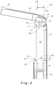
- Figure 2 illustrates the device 100 with the lever 40 in the opened configuration, before insertion of a pod 200 in the pod compartment 20.
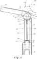
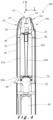
- Figures 3 and 4 illustrate a system 300 according to the invention, comprising the device of figure 1 and a pod 200 inserted in the pod compartment 20, with the lever 40 respectively in the opened and in the closed configuration.
- the lever 40 is pivotably mounted on the casing 10 around a rotation axis X1 orthogonal to the longitudinal direction Z.
- the lever 40 is an eccentric lever with a base portion 44 intersecting the rotation axis X1, and a covering portion 46 that serves as an obturator for the opening 24 of the pod compartment 20, in the closed configuration of the lever 40.
- the covering portion 46 is typically provided with a grasping part 45, for example at its distal or bottom end, that facilitates actuation of the lever 40 by the user.
- the casing may also be provided with a notch or any otherwise adapted opening enabling the user to introduce a finger therein to lift the lever 40.
- the base portion 44 has a cam-shaped profile, with a curved sliding surface arranged to contact and slide against the pod inserted inside the pod compartment upon pivoting the lever.
- a distance of the sliding surface to the rotation axis X1 varies along the said surface. More specifically, the sliding surface 47 is arranged so that a distance L1, measured longitudinally between the rotation axis X1 and the bottom surface of the base portion 44 (i.e along a longitudinal line passing through the axis X1), is strictly smaller, preferably at least 20% smaller, in the opened configuration (L1) than in the closed configuration (L1').
- the base portion 44 of the lever 40 comes into longitudinal abutting contact with the pod 200 in the closed configuration but is spaced therefrom in the opened configuration.
- the lever 40 applies a longitudinal constraint on the pod 200, which constraint is released again in the opened configuration.
- the longitudinal constraint applied on the pod 200 in the closed configuration ensures that it is tightly maintained inside the compartment 20
- the release of the longitudinal constraint in the opened position facilitates the insertion or removal of the pod 200, hence facilitating operation by the user.
- the contact between the thermal interface 250 of the pod 200 and the heater 32 is ensured during use, even in case the device 10 falls down or undergoes other impacts or vibrations.
- the lever has - apart from its curved sliding surface 47 for sliding cooperation with the pod 200 - also a substantially planar blocking surface 48 extending from said curved sliding surface 47 and configured to be arranged transversally in the closed configuration of the lever 40. This prevents unexpected disengagement once the pod 200 is blocked in its operation position.
- the device 10 comprises at least one heater biasing means 34 urging the heater 32 towards the top end 21 of the pod compartment 20.
- the at least one heater biasing means 34 may comprise at least one spring, as shown in figure 1 , or at least one deformable blade or any other adapted resilient biasing means.
- This embodiment reduces an effort that has to be provided by the user for closing the pod compartment 20, while ensuring at the same time a sufficient pressing force between the pod 200 and the heater 32. This also ensures a better contact between the heater 32 and the thermal interface 250 of the pod 200.
- the heater biasing means 34 also prevent vibrations/constraints applied on the pod 200 to be transmitted to the heater 32. In particular when the heater 32 is made of a fragile material such as ceramic, this prevents that it gets broken if too much pressure is applied from the pod 200 or if the device 100 falls.
- This pressure force between the pod 200 and heater 32 is a key issue for improving global efficiency of the device 10 and in particular increasing the aerosol collected mass (mass of aerosol collected after a defined number of puffs) by increasing the heat transfer efficiency between the heater and the pod.
- the pressure force should preferably be comprised between 10 and 20N.
- the heater 32 could also be fixed and the required pressing force may then correspond to the longitudinal constraint applied by the sole lever 40.
- the pod 200 When the pod 200 is manually inserted in the pod compartment 20, in an opened configuration of the lever 40, the pod 200 comes into abutment with the top end surfaces 26a, 26b surrounding the lever 40 and with the heater 32 and/or the bottom end surface(s) 28 of the pod compartment 20. As shown in figure 3 , the pod 200 extends in the longitudinal direction Z, inside the pod compartment 20, once inserted therein by the user.
- the top end surfaces 26a, 26b are arranged farther from the rotation axis X1 (in the longitudinal direction Z) than the bottom surface of the base portion 44 in the opened configuration.
- top end surfaces 26a, 26b are further arranged closer to the rotation axis X1 (in the longitudinal direction) than the bottom surface of the base portion 44 in the closed configuration.
- the lever 40 when the lever 40 is moved in the closed configuration, the lever 40 comes into contact with the top end of the pod 200 and progressively pushes on the pod 200 downwards towards the bottom end 102 of the device 100.
- the pod 200 is either moved towards the heater 32, in particular in a case where the heater 32 is spring biased as in the illustrated embodiment, or simply maintained firmly against the heater 32.
- the cam-shaped base portion 44 may be further configured so that a distance L1, measured longitudinally between the rotation axis X1 and the bottom surface of the base portion 44, is higher in an intermediate configuration between the opened and closed configurations (L1") than in the closed configuration (L1').
- the pressure exerted on the pod 200 is then higher in this intermediate configuration than in the closed configuration.
- the spring 34 is still further compressed and then released again, resulting in the pod 200 being ejected in the upward direction.
- the removal of the pod 200 is hence facilitated.
- the lever 40 is located at a top end 101 of the device 100 and the lever 40 itself forms a mouthpiece. Accordingly, the lever 40 comprises an integrated airpath 50 through which the user draws the aerosol when vaping, and configured to communicate with the airpath 230 of the pod 200 received in the pod compartment 20.
- the integrated airpath 50 is formed in the cam-shaped base portion 44 of the lever.
- the airpath 50 forms a rectilinear canal, provided with top and bottom openings 51, 52.
- the canal has its top end portion 54 flared towards the top opening 51, to facilitate interaction with the user's mouth.
- the device 100 further comprises sealing means 56 at the bottom end 52 of the integrated airpath 50.
- the sealing means 56 may be a sealing ring, possibly a silicone sealing ring.
- the sealing means 56 surround the top opening of the airpath 230 of the pod 200 and provide an airtight barrier between the airpath 50 of the lever 40 and that 230 of the pod 200.
- Figures 6 and 7 illustrate an aerosol-generating device 100 according to a second embodiment. All features common to the previous embodiment are not described again and shall be considered applicable to this second embodiment.
- the heater 32 is further protected by a heater protector 60, that comprises a movable screen 62 and at least one protector biasing member 64 urging the movable screen 62 towards a protection position in which the heater 32 is shielded by said movable screen 62 against impingement of external objects within at least one angular sector.
- a heater protector 60 that comprises a movable screen 62 and at least one protector biasing member 64 urging the movable screen 62 towards a protection position in which the heater 32 is shielded by said movable screen 62 against impingement of external objects within at least one angular sector.
- the movable screen 62 be arranged above the heater 32 in the longitudinal direction Z.
- the movable screen 62 may for example be arranged flush with the top heater surface (here the contacting surface 33a).
- the pod 200 is so configured that it maintains the movable screen 62 in a retracted position in which the heater 32 can interact with the heating interface 250 of said pod 200 for the operation of the aerosol-generating device 100, when in the operation position.
- the pod 200 is arranged to push the movable screen 62 into the retracted position against the at least one protector biasing member 64, when displaced towards its operation position.
- the heater protector 60 according to one possible embodiment is illustrated in figure 7 :
- the movable screen 62 is typically plate-shaped with an outer section substantially corresponding to an inner section of the pod compartment 20 and provided with an opening 66 configured to expose the heater 32.
- the pod 200 When in its operation-position, the pod 200 contacts the heater 32 at the contact zone 33 thereof through the opening 66 of the movable screen 62.
- a total return force that is applied by the at least one protector biasing member 64 onto the movable screen 62 shall be less that the force applied by a heater biasing member 34 on the heater 32.
- the at least one protector biasing member 64 comprises at least two springs, preferably three or four springs, preferably arranged symmetrically around the opening 66.
- Each protector biasing member 64 extends between the movable screen 62 and at least one supporting portion 16 that is fixed relative to the casing 10.
- guiding rods 70 can be provided for guiding the translation of the movable screen 62 between the protection position and the retracted position.
- Each spring 64 is typically arranged around a respective one of the guiding rods 70.
- each guiding rod 70 may be provided with a hard stop 72 at one end, said hard stop 72 being arranged to abut against the at least one supporting portion 16, thereby defining the protection position for the movable screen 62.
- the device may further comprise linear bearings 74 each arranged between one of the guiding rods 70 and the at least one supporting portion, whereby each guiding rod 70 slides in the corresponding linear bearing 74 when the movable screen 62 moves from the protection position to the retracted position or reverse.
Landscapes
- Engineering & Computer Science (AREA)
- Human Computer Interaction (AREA)
- Catching Or Destruction (AREA)
Abstract
The present invention relates to an aerosol-generating aerosol-generating device (100) comprising a casing (10) housing a pod compartment (20) extending in a longitudinal direction (Z) and an opening (24) to provide access to said pod compartment (20), a heater (32) arranged at a bottom end (22) of the pod compartment (20), and a lever (40) configured to apply a longitudinal constraint on a pod (200) received inside the pod compartment (20).
Description
- The present invention relates to the field of tobacco, in particular to aerosol-generating devices, and more specifically to e-cigarettes.
- E-cigarettes operate by heating a liquid solution - called e-liquid - to a certain temperature so that it produces an aerosol to be inhaled by the user. The e-liquid is typically stored in the storage reservoir of a e-liquid container called pod, that is either refillable by the user or disposable. The pod is placed in a compartment of a device, where it is heated by a dedicated heater.
- A long-standing challenge in aerosol generating devices concerns the introduction and removal of pods in the device. These operations should not necessitate particular attention or effort by the user. Still, the pod should be held firmly in the device to steadily contact the heater so that heat is provided continuously and efficiently during a vaping session. In particular, the pod holder should be mechanically stable and should avoid disengagement due to vibrations or impacts. It should further be designed so that the pod cannot pop out of the device when dropped.
- The object of the present invention is to propose an aerosol-generating device in which introduction and removal of the pods are operated conveniently and which further provides a strong hold for the pod in use.
- According to the present invention, this object is achieved through the features of independent claim 1. Further advantageous embodiments result from the dependent claims and the description.
- An aerosol-generating device according to the invention comprises:
- a casing housing a pod compartment extending in a longitudinal direction between a top end and a bottom end, the pod compartment being arranged for accommodating a pod to be heated during an operation of the aerosol-generating device,
- an opening for insertion and removal of the pod in said pod compartment,
- a heater arranged at the bottom end of the pod compartment, and
- a lever pivotably mounted on the casing between an opened configuration in which it exposes the pod compartment through the opening and a closed configuration in which it closes the opening, wherein the lever is configured to apply a longitudinal constraint on the pod and towards the heater in the closed configuration and release said constraint in the opened configuration.
- The lever is configured to apply a longitudinal constraint on a pod received inside the pod compartment upon pivoting from the opened towards the closed configuration, and then maintain a nominal longitudinal constraint on said pod in the closed configuration. Upon pivoting between its opened towards its closed configuration, the lever comes into longitudinal abutting contact with the pod and then longitudinally pushes on the pod, which hence is urged towards the heater.
- The pod can be either actively displaced towards the heater (if the device provides a degree of freedom for longitudinal translation of the pod inside the compartment, as will be described hereafter) or simply blocked against any movement in the longitudinal direction and away from the heater.
- Hence the device may be so configured that a rotation of the lever from its opened towards its closed configuration induces a translation of the pod towards the heater. Or, as an alternative, the pod may not be moved upon actuating the lever, which may act as a simple abutment or stop.
- The lever finally releases the longitudinal constraint applied on the pod upon pivoting again in its opened configuration.
- The insertion of a pod in the device occurs as follows: the pod is firstly placed inside the pod compartment, by the user. Once the pod is arranged in the compartment, typically with its main axis aligned or parallel to the longitudinal direction of the compartment, the lever is activated by the user to secure and/or adjust a longitudinal position of the pod inside the compartment. The position of the pod inside the pod compartment and in the closed configuration of the lever is called hereinafter operation position.
- The invention hence provides a user-friendly removing and inserting system of the pod inside the device. With the particular lever mechanism, the opening of the pod compartment can be sufficiently large to facilitate insertion or removal of the pod when the lever is opened, but at the same time the pod can be tightly maintained inside the device (and in particular urged downwards towards the heater) when the lever is closed.
- Furthermore, as the heater is part of the device, the pod complexity is reduced, and so are the related costs.
- According to an example, the lever may have a curved sliding surface for sliding cooperation with the pod received in the pod compartment. The curved sliding surface allows the pod to be smoothly inserted and blocked against the heater, with no abrupt movement. Such user-friendly design also prevents that the pod and/or device be damaged upon use.
- Advantageously, the lever may also be provided with a substantially planar blocking surface configured to be arranged orthogonally to the longitudinal direction in the closed configuration of the lever to apply the longitudinal constraint. In the closed configuration, the planar blocking surface cooperates with the pod to apply thereon the longitudinal constraint,. Planar cooperation between the blocking surface and the pod tends to maintain the pod and lever in the closed configuration and prevents unexpected disengagement of the pod.
- The heater has typically a contact zone, comprising for example a ceramic material surface portion, configured to interact with a heating interface of the pod.
- Advantageously, a resulting pressing force between the pod and the heater in the closed configuration of the lever is between 10 and 20 N. This pressing force issues either from the pressure exerted by the sole lever or from a combination of this pressure exerted by the lever and that exerted on the heater by heater biasing means such as will be defined hereafter.
- Due to the lever mechanism, the force required for opening or closing the lever is much lower (for example between 3-5N depending on the lever length) than the pressure force actually applied by the lever on the pod (typically between 10 and 20 N as mentioned hereabove).
- Typically, the device has a top end either provided with or configured to receive a mouthpiece and a bottom end, and the top end of the pod compartment is oriented towards the top end of the device and the bottom end of the pod compartment is oriented towards the bottom end of the device. In particular, a longitudinal direction of the device is parallel to the longitudinal direction of the pod compartment.
- Typically, the pod compartment is fixed with respect to the casing.
- Typically, the pod compartment is at least partially delimited by the casing and the opening for insertion and removal of the pod in the pod compartment is formed in the casing.
- According to an example, the opening for insertion and removal of the pod in the pod compartment is a lateral opening, i.e. an opening oriented orthogonally to the longitudinal direction of the pod compartment.
- According to an example, the lever may be pivotably mounted on the casing around a rotation axis orthogonal to the longitudinal direction.
- According to an example, the rotation axis may be located at a top or proximal end of the device.
- According to an example, the lever may be an eccentric lever having a grasping portion and a cam-shaped base portion intersecting the rotation axis.
- According to an example, the lever may be configured such that a distance, measured longitudinally between the rotation axis and the bottom surface of the base portion, is strictly smaller, preferably at least 20% smaller, in the opened configuration than in the closed configuration.
- According to an example, the device may comprise at least one heater biasing member urging the heater towards the top end of the pod compartment. With such configuration, a sufficient pressure force is achieved between the pod and heater also with a limited force induced by the lever (and consequently by the user) itself. Hence heat transfer to the heating interface of the pod and global efficiency of the device are improved and the aerosol generated mass is relatively increased.
- According to an example, the lever may be configured such that a distance, measured longitudinally between the rotation axis and the bottom surface of the base portion, is higher in an intermediate configuration between the opened and closed configurations than in the closed configuration.
- In the case of a spring-loaded heater, this results in the pod being upwardly ejected when opening the pod compartment, hence further facilitating the removal thereof by the user.
- Since the heater is integrated in the device and needs to be reused for the whole lifespan of the device, it should be well protected, especially when replacing the pod. In this context, it may be advantageous to provide a heater protector with a semi-automatic retraction mechanism.
- According to an example, such heater protector may comprise a - for example plate-shaped- screen that is movable between a protection position in which the heater is shielded by said movable screen and a retracted position in which the heater is functional with respect to the pod for operation of the device, with the heater protector comprising at least one protector biasing member configured to urge the movable screen towards the protection position.
- The protection position is typically a position where the heater is shielded by the movable screen against external objects getting closer to said heater within at least an angular sector of impingement.
- The retracted position is typically a position where at least a contact zone of the heater protrudes from the movable screen.
- According to an example, the device is arranged so that loading the pod in its operation-position inside the casing causes said pod to push the movable screen into the retracted position against the at least one protector biasing member.
- According to an example, the movable screen is provided with an opening forming a passage for at least a contact zone of the heater. The opening is so arranged that the pod when in the operation-position contacts the heater at a contact zone of said heater through the opening of said movable screen, and the movable screen when in the protection position is maintained by the at least one protector biasing member at a distance above a level of the contact zone of the heater.
- According to an example, the at least one protector biasing member comprises at least two springs, preferably three or four springs, which each extend between the movable screen and at least one supporting portion that is fixed relative to the casing.
- According to an example, the heater protector further comprises guiding rods arranged for guiding and/ or stopping a translation of the movable screen between the protection position and the retracted position.
- According to an example, each guiding rod is provided with a hard stop at one end of said guiding rod, said hard stop being arranged to abut against the at least one supporting portion, thereby defining the protection position for the movable screen.
- According to an example, the device further comprises linear bearings each arranged between one of the guiding rods and the at least one supporting portion, whereby each guiding rod slides in the corresponding linear bearing when the movable screen moves from the protection position to the retracted position or reverse.
- According to an example, each spring is arranged around a respective one of the guiding rods.
- According to an example, the at least one heater biasing member is selected such that a force applied by said heater biasing member(s) onto the heater is higher than a total return force that is applied by the at least one protector biasing member onto the movable screen.
- According to an example, the lever may further comprise an integrated airpath configured to communicate with an airpath of a pod received in the pod compartment. Hence, the consumer's mouth comes in direct contact with the device and not the pod when vaping. Due to the longitudinal constraint applied on the pod by the lever in closed position, sealing is achieved easily between the airpath of the lever and that of the pod.
- According to an example, the device may further comprise a sealing means at a bottom end of the integrated airpath.
- According to an example, the integrated airpath may be formed in the cam-shaped portion of the lever and may define an opening at the planar blocking surface, in the case of an eccentric lever. In this case, the sealing means may be arranged around the opening.
- In an alternative example, however, a fixed airpath may be formed in the upper portion of the casing and may be configured to communicate with an airpath of the pod once the pod is inserted in its compartment. In such example, the spring-loaded mechanism of the heater may urge the pod against sealing means surrounding the fixed air path at its bottom end.
- Preferably, the integrated air path of the device communicates in straight arrangement with the air path of the pod.
- In a second aspect, the invention is also achieved by a system for generating an aerosol, which comprises:
- a device as described hereabove, and
- a pod configured to be inserted in the pod compartment of said device.
- In particular, the pod may comprise an airpath opened at a top end and a heating interface at a bottom end configured to cooperate with the heater.
- The lever may also comprise an integrated airpath, with said integrated airpath being configured to be aligned and communicate with an airpath of the pod inserted in the pod compartment in the closed configuration of the lever.
-
-
Figure 1 illustrates an aerosol-generating device according to an embodiment of the invention, and a pod for insertion inside this device. -
Figure 2 is a partial cut view of the aerosol-generating device offigure 1 , with an empty pod compartment and the lever in an opened configuration. -
Figure 3 is a partial cut view of an aerosol-generating system comprising the aerosol-generating device offigure 1 and a pod inserted in the pod compartment, with the lever still in its opened configuration. -
Figure 4 is a partial cut view of an aerosol-generating system comprising the aerosol-generating device offigure 1 and a pod inserted in the pod compartment, with the lever in a closed configuration and the pod in its operation-position. -
Figure 5 is a partial cut view of an aerosol-generating system comprising the aerosol-generating device offigure 1 and a pod inserted in the pod compartment, with the lever in an intermediate configuration between the closed and the opened configuration. -
Figure 6 illustrates an aerosol-generating device according to another embodiment of the invention, comprising a heater protector with a screen for shielding the heater when not in use, the figure illustrating the retracted position of the screen during use. -
Figure 7 illustrates the heater protector offigure 6 in more detail, in the protection position of the movable screen. - The present invention will be described with respect to particular embodiments and with reference to the appended figures, but the invention is not limited thereto. The described figures are only schematic and are non-limiting. In the figures, the size of some of the elements may be exaggerated and not drawn on scale for illustrative purposes. The dimensions and the relative dimensions do not correspond to actual reductions to the practice of the invention.
-
Figure 1 illustrates an aerosol-generatingdevice 100 according to an embodiment of the present invention, and apod 200 for use in combination with saiddevice 100. - The
device 100 is delimited by arigid frame 10, herein called casing. - The
device 100 extends in a longitudinal direction Z, between atop end 101 and abottom end 102. - Herein, the
top end 101 of thedevice 100 is to be understood as the end of saiddevice 100 that is directed towards the user's mouth, during vaping. Thetop end 101 is either provided with or configured to receive a mouthpiece on which the user draws when vaping. - The
bottom end 102 of the device is opposite to thetop end 101, in the longitudinal direction Z. - More generally, when referring to any part of the
device 100 or to apod 200 that shall be inserted therein, a top end of the said part is oriented (or intended to be oriented) towards the top end of the device and a bottom end thereof is oriented (or intended to be oriented) towards the bottom end of the device, in the longitudinal direction. - A lateral direction is orthogonal to the longitudinal direction Z, and a transversal plane X-Y is orthogonal to the longitudinal direction Z.
- As illustrated, the
casing 10 may have an elongated shape in the longitudinal direction Z. This, however, shall not be considered limiting. - As shown in
figure 1 , thedevice 100 has apod compartment 20 for accommodating apod 200 to be heated during use of saiddevice 100. - The
pod compartment 20 extends between atop end 21 and abottom end 22 and has anopening 24 for the insertion and removal of thepod 200. In the illustrated embodiment, theopening 24 is a lateral opening (i.e., that opens in a direction perpendicular to the longitudinal direction Z). - The
device 100 further comprises heating means 30 for heating thepod 200 inside thecompartment 20. Said heating means 30 comprise aheater 32 arranged at abottom end 22 of thepod compartment 20, and anelectrical power source 36, typically a battery, housed inside thecasing 10 and supplying theheater 32. - The
heater 32 is for example pin-shaped with at least onecontact zone 33 at its top end oriented towards the interior of thepod compartment 20. The contact zone comprises for example a surface made of ceramic material. - At its
top end 21, thepod compartment 20 is at least partially delimited in the longitudinal direction Z by at least one top end surface here in the form of two spaced apartlateral shoulders bottom end 22, thepod compartment 20 is at least partially delimited in the longitudinal direction Z by at least onebottom end surface 28 surrounding theheater 32. In the example, thebottom end surface 28 is formed by apart 16 of thecasing 10 extending in a transversal plane. - A
pod 200, as illustrated infigure 1 , typically comprises abody 210 mostly of cylindrical or parallelepipedal shape having opposite top and bottom ends 211, 212, an internalliquid storage reservoir 220 to receive an e-liquid, an air-path 230 passing through the internalliquid storage reservoir 220, eventually a closable opening (not shown) for refilling thereservoir 220 when it is empty, and athermal interface 250, rendered accessible through anopening 214 of thebody 210, typically at thebottom end 212 thereof. Thethermal interface 250 can be formed by or be in contact with a wick arranged in fluid communication with thereservoir 220. The wick can be formed by a solid porous element which conducts and evaporates the liquid to the air-path 230 upon heating through thethermal interface 250. - In operation of the device, the
thermal interface 250 of thepod 200 is in contact with thecontact zone 33 of theheater 32, so that thepod 200 and hence the e-liquid contained therein can be heated for producing an aerosol. - According to the invention, the
device 100 comprises alever 40 for closing thepod compartment 20 and maintaining thepod 200 inside thecasing 10 and in close contact with theheater 32. - As illustrated for instance in
figure 1 , thelever 40 is pivotably mounted on thecasing 10 between an opened configuration in which it exposes thepod compartment 20 and a closed configuration in which it closes thelateral opening 24. -
Figure 2 illustrates thedevice 100 with thelever 40 in the opened configuration, before insertion of apod 200 in thepod compartment 20.Figures 3 and4 illustrate asystem 300 according to the invention, comprising the device offigure 1 and apod 200 inserted in thepod compartment 20, with thelever 40 respectively in the opened and in the closed configuration. - The
lever 40 is pivotably mounted on thecasing 10 around a rotation axis X1 orthogonal to the longitudinal direction Z. - According to a preferable embodiment, as illustrated, the
lever 40 is an eccentric lever with abase portion 44 intersecting the rotation axis X1, and a coveringportion 46 that serves as an obturator for theopening 24 of thepod compartment 20, in the closed configuration of thelever 40. The coveringportion 46 is typically provided with a graspingpart 45, for example at its distal or bottom end, that facilitates actuation of thelever 40 by the user. In addition or as an alternative, the casing may also be provided with a notch or any otherwise adapted opening enabling the user to introduce a finger therein to lift thelever 40. - In a sectional plane orthogonal to the rotation axis X1, as shown in
figures 2 to 5 , thebase portion 44 has a cam-shaped profile, with a curved sliding surface arranged to contact and slide against the pod inserted inside the pod compartment upon pivoting the lever. A distance of the sliding surface to the rotation axis X1 varies along the said surface. More specifically, the slidingsurface 47 is arranged so that a distance L1, measured longitudinally between the rotation axis X1 and the bottom surface of the base portion 44 (i.e along a longitudinal line passing through the axis X1), is strictly smaller, preferably at least 20% smaller, in the opened configuration (L1) than in the closed configuration (L1'). - Hence, the
base portion 44 of thelever 40 comes into longitudinal abutting contact with thepod 200 in the closed configuration but is spaced therefrom in the opened configuration. In the closed configuration thelever 40 applies a longitudinal constraint on thepod 200, which constraint is released again in the opened configuration. - This has several advantages:
While the longitudinal constraint applied on thepod 200 in the closed configuration ensures that it is tightly maintained inside thecompartment 20, the release of the longitudinal constraint in the opened position facilitates the insertion or removal of thepod 200, hence facilitating operation by the user. Further, the contact between thethermal interface 250 of thepod 200 and theheater 32 is ensured during use, even in case thedevice 10 falls down or undergoes other impacts or vibrations. - According to an advantageous embodiment, the lever has - apart from its curved sliding
surface 47 for sliding cooperation with the pod 200 - also a substantially planar blockingsurface 48 extending from said curved slidingsurface 47 and configured to be arranged transversally in the closed configuration of thelever 40. This prevents unexpected disengagement once thepod 200 is blocked in its operation position. - According to an advantageous embodiment, as illustrated, the
device 10 comprises at least one heater biasing means 34 urging theheater 32 towards thetop end 21 of thepod compartment 20. - The at least one heater biasing means 34 may comprise at least one spring, as shown in
figure 1 , or at least one deformable blade or any other adapted resilient biasing means. - This embodiment reduces an effort that has to be provided by the user for closing the
pod compartment 20, while ensuring at the same time a sufficient pressing force between thepod 200 and theheater 32. This also ensures a better contact between theheater 32 and thethermal interface 250 of thepod 200. - The heater biasing means 34 also prevent vibrations/constraints applied on the
pod 200 to be transmitted to theheater 32. In particular when theheater 32 is made of a fragile material such as ceramic, this prevents that it gets broken if too much pressure is applied from thepod 200 or if thedevice 100 falls. - This pressure force between the
pod 200 andheater 32 is a key issue for improving global efficiency of thedevice 10 and in particular increasing the aerosol collected mass (mass of aerosol collected after a defined number of puffs) by increasing the heat transfer efficiency between the heater and the pod. - To ensure good heat transfer, the pressure force should preferably be comprised between 10 and 20N.
- In the case of a spring-biased
heater 32 as mentioned hereabove, the force that has to be applied on thelever 40 to close thepod compartment 20 and press thepod 200 sufficiently against theheater 32 is diminished: a part of the required pressing force is already provided by the heater biasing means 34. - As an alternative, however, the
heater 32 could also be fixed and the required pressing force may then correspond to the longitudinal constraint applied by thesole lever 40. - When the
pod 200 is manually inserted in thepod compartment 20, in an opened configuration of thelever 40, thepod 200 comes into abutment with thetop end surfaces lever 40 and with theheater 32 and/or the bottom end surface(s) 28 of thepod compartment 20. As shown infigure 3 , thepod 200 extends in the longitudinal direction Z, inside thepod compartment 20, once inserted therein by the user. - To ensure that the pod does not contact the
lever 40 in the opened configuration, thetop end surfaces base portion 44 in the opened configuration. - The
top end surfaces base portion 44 in the closed configuration. - As a consequence, when the
lever 40 is moved in the closed configuration, thelever 40 comes into contact with the top end of thepod 200 and progressively pushes on thepod 200 downwards towards thebottom end 102 of thedevice 100. Thepod 200 is either moved towards theheater 32, in particular in a case where theheater 32 is spring biased as in the illustrated embodiment, or simply maintained firmly against theheater 32. - In the case of a spring
biased heater 32 as illustrated infigure 5 , the cam-shapedbase portion 44 may be further configured so that a distance L1, measured longitudinally between the rotation axis X1 and the bottom surface of thebase portion 44, is higher in an intermediate configuration between the opened and closed configurations (L1") than in the closed configuration (L1'). - The pressure exerted on the
pod 200 is then higher in this intermediate configuration than in the closed configuration. Upon opening thelever 40, thespring 34 is still further compressed and then released again, resulting in thepod 200 being ejected in the upward direction. The removal of thepod 200 is hence facilitated. - In the illustrated embodiment, the
lever 40 is located at atop end 101 of thedevice 100 and thelever 40 itself forms a mouthpiece. Accordingly, thelever 40 comprises anintegrated airpath 50 through which the user draws the aerosol when vaping, and configured to communicate with theairpath 230 of thepod 200 received in thepod compartment 20. - In the embodiment, the
integrated airpath 50 is formed in the cam-shapedbase portion 44 of the lever. The airpath 50 forms a rectilinear canal, provided with top andbottom openings - Advantageously, the canal has its
top end portion 54 flared towards thetop opening 51, to facilitate interaction with the user's mouth. - To ensure that the aerosol does not leak between the
pod 200 andlever 40, thedevice 100 further comprises sealing means 56 at thebottom end 52 of theintegrated airpath 50. - The sealing means 56 may be a sealing ring, possibly a silicone sealing ring.
- In the closed configuration of the
lever 40, the sealing means 56 surround the top opening of theairpath 230 of thepod 200 and provide an airtight barrier between theairpath 50 of thelever 40 and that 230 of thepod 200. -
Figures 6 and7 illustrate an aerosol-generatingdevice 100 according to a second embodiment. All features common to the previous embodiment are not described again and shall be considered applicable to this second embodiment. - Here, the
heater 32 is further protected by aheater protector 60, that comprises amovable screen 62 and at least oneprotector biasing member 64 urging themovable screen 62 towards a protection position in which theheater 32 is shielded by saidmovable screen 62 against impingement of external objects within at least one angular sector. - In the protection position, it is (although possible) not mandatory that the
movable screen 62 be arranged above theheater 32 in the longitudinal direction Z. As illustrated, themovable screen 62 may for example be arranged flush with the top heater surface (here the contactingsurface 33a). - The
pod 200 is so configured that it maintains themovable screen 62 in a retracted position in which theheater 32 can interact with theheating interface 250 of saidpod 200 for the operation of the aerosol-generatingdevice 100, when in the operation position. - Typically, the
pod 200 is arranged to push themovable screen 62 into the retracted position against the at least oneprotector biasing member 64, when displaced towards its operation position. - The
heater protector 60 according to one possible embodiment is illustrated infigure 7 : Themovable screen 62 is typically plate-shaped with an outer section substantially corresponding to an inner section of thepod compartment 20 and provided with anopening 66 configured to expose theheater 32. - When in its operation-position, the
pod 200 contacts theheater 32 at thecontact zone 33 thereof through theopening 66 of themovable screen 62. - A total return force that is applied by the at least one
protector biasing member 64 onto themovable screen 62 shall be less that the force applied by aheater biasing member 34 on theheater 32. - The at least one
protector biasing member 64 comprises at least two springs, preferably three or four springs, preferably arranged symmetrically around theopening 66. - Each
protector biasing member 64 extends between themovable screen 62 and at least one supportingportion 16 that is fixed relative to thecasing 10. - Advantageously, guiding
rods 70 can be provided for guiding the translation of themovable screen 62 between the protection position and the retracted position. Eachspring 64 is typically arranged around a respective one of the guidingrods 70. - For example, each guiding
rod 70 may be provided with ahard stop 72 at one end, saidhard stop 72 being arranged to abut against the at least one supportingportion 16, thereby defining the protection position for themovable screen 62. - The device may further comprise
linear bearings 74 each arranged between one of the guidingrods 70 and the at least one supporting portion, whereby each guidingrod 70 slides in the correspondinglinear bearing 74 when themovable screen 62 moves from the protection position to the retracted position or reverse.
Claims (15)
- An aerosol-generating device (100) comprising:- a casing (10) housing a pod compartment (20) extending in a longitudinal direction (Z) between a top end (21) and a bottom end (22), the pod compartment (20) being arranged for accommodating a pod (200) to be heated during an operation of the aerosol-generating device (100),- an opening (24) for insertion and removal of the pod (200) in said pod compartment (20),- a heater (32) arranged at the bottom end (22) of the pod compartment (20), and- a lever (40) pivotably mounted on the casing (10) between an opened configuration in which it exposes the pod compartment (20) through the opening (24) and a closed configuration in which it closes the opening (24), wherein the lever (40) is configured to apply a longitudinal constraint on the pod (200) in the closed configuration and release said constraint in the opened configuration.
- The device (100) according to claim 1, wherein the lever (40) has a curved sliding surface (47) for sliding cooperation with the pod (200) received in the pod compartment (20) and a substantially planar blocking surface (48) configured to be arranged orthogonally to the longitudinal direction (Z) in the closed configuration of the lever (40) to apply said longitudinal constraint.
- The device (100) according to claim 1 or 2, wherein a resulting pressing force between the pod (200) and the heater (32) in the closed configuration of the lever (40) is between 10 and 20 N.
- The device (100) according to any one of claims 1 to 3, so configured that a rotation of the lever (40) from its opened towards its closed configuration induces a translation of the pod (200) towards the heater (32).
- The device (100) according to any one of claims 1 to 4, further comprising at least one heater biasing element (34) urging the heater (32) towards the top end (21) of the pod compartment (20).
- The device (100) according to claim any one of claims 1 to 5, wherein the lever (40) is pivotably mounted on the casing (10) around a rotation axis (X1) orthogonal to the longitudinal direction (Z).
- The device (100) according to claim 6, wherein the lever (40) is an eccentric lever having a grasping portion (46) and a cam-shaped base portion (44) intersecting the rotation axis (X1).
- The device (100) according to claim 7, wherein a distance (L1, L1'), measured longitudinally between the rotation axis (X1) and the bottom surface of the base portion (44), is strictly smaller, preferably at least 20% smaller, in the opened configuration (L1) than in the closed configuration (L1') of the lever.
- The device (100) according to claim 8, wherein the eccentric lever (40) is configured so that a distance (L1, L1', L1"), measured longitudinally between the rotation axis (X1) and the bottom surface of the base portion (44), is higher in an intermediate configuration (L1") of the lever between the opened and closed configurations than in the closed configuration (L1').
- The device (100) according to any one of claims 1 to 9, wherein the lever (40) comprises an integrated airpath (50) configured to communicate with an airpath (230) of a pod (200) received in the pod compartment (20).
- The device (100) according to claims 7 and 10, wherein the integrated airpath (50) is formed in the cam-shaped portion (44).
- The device (100) according to any one of claims 1 to 11, wherein the opening (24) for insertion and removal of the pod (200) in the pod compartment (20) is a lateral opening.
- The device (100) according to any one of claims 1 to 12, further comprising a heater protector (60), preferably provided with an opening (66) forming a passage for at least a contact zone (33) of the heater (32), the heater protector comprising a screen (62) movable between a protection position in which the heater (32) is shielded by said movable screen (62) and a retracted position in which the heater (32) is functional with respect to the pod (200) for operation of the device, with the heater protector (60) comprising at least one protector biasing member (64) configured to urge the movable screen (62) towards the protection position.
- A system (300) for generating an aerosol, comprising:- a device (100) according to any one of claims 1 to 13, and- a pod (200) configured to be inserted in the pod compartment (20) of the device (100).
- The system (300) according to claim 14, wherein the pod (200) comprises an airpath (230) opened at a top end (211) and a heating interface (250) at a bottom end (212) configured to cooperate with the heater (32), and preferably the lever (40) comprises an integrated airpath (50) aligned and communicating with the airpath (250) of the pod (200) in the closed configuration of the lever (40).
Priority Applications (2)
| Application Number | Priority Date | Filing Date | Title |
|---|---|---|---|
| EP23192096.8A EP4508995A1 (en) | 2023-08-18 | 2023-08-18 | Aerosol-generating device |
| US18/804,360 US20250057224A1 (en) | 2023-08-18 | 2024-08-14 | Aerosol-Generating Device |
Applications Claiming Priority (1)
| Application Number | Priority Date | Filing Date | Title |
|---|---|---|---|
| EP23192096.8A EP4508995A1 (en) | 2023-08-18 | 2023-08-18 | Aerosol-generating device |
Publications (1)
| Publication Number | Publication Date |
|---|---|
| EP4508995A1 true EP4508995A1 (en) | 2025-02-19 |
Family
ID=87747938
Family Applications (1)
| Application Number | Title | Priority Date | Filing Date |
|---|---|---|---|
| EP23192096.8A Withdrawn EP4508995A1 (en) | 2023-08-18 | 2023-08-18 | Aerosol-generating device |
Country Status (2)
| Country | Link |
|---|---|
| US (1) | US20250057224A1 (en) |
| EP (1) | EP4508995A1 (en) |
Citations (5)
| Publication number | Priority date | Publication date | Assignee | Title |
|---|---|---|---|---|
| US20090151717A1 (en) * | 2007-12-18 | 2009-06-18 | Adam Bowen | Aerosol devices and methods for inhaling a substance and uses thereof |
| WO2018141467A1 (en) * | 2017-01-31 | 2018-08-09 | Philip Morris Products S.A. | Aerosol-generating device and aerosol-generating system |
| US20180368475A1 (en) * | 2015-11-12 | 2018-12-27 | Fontem Holdings 1 B.V. | Electronic smoking device with cavity for liquid reservoir |
| WO2022113361A1 (en) * | 2020-11-30 | 2022-06-02 | 日本たばこ産業株式会社 | Power unit for non-combustion-type inhaler and non-combustion-type inhaler |
| US20230034238A1 (en) * | 2019-12-19 | 2023-02-02 | Jt International S.A. | Aerosol Generation Device |
-
2023
- 2023-08-18 EP EP23192096.8A patent/EP4508995A1/en not_active Withdrawn
-
2024
- 2024-08-14 US US18/804,360 patent/US20250057224A1/en active Pending
Patent Citations (5)
| Publication number | Priority date | Publication date | Assignee | Title |
|---|---|---|---|---|
| US20090151717A1 (en) * | 2007-12-18 | 2009-06-18 | Adam Bowen | Aerosol devices and methods for inhaling a substance and uses thereof |
| US20180368475A1 (en) * | 2015-11-12 | 2018-12-27 | Fontem Holdings 1 B.V. | Electronic smoking device with cavity for liquid reservoir |
| WO2018141467A1 (en) * | 2017-01-31 | 2018-08-09 | Philip Morris Products S.A. | Aerosol-generating device and aerosol-generating system |
| US20230034238A1 (en) * | 2019-12-19 | 2023-02-02 | Jt International S.A. | Aerosol Generation Device |
| WO2022113361A1 (en) * | 2020-11-30 | 2022-06-02 | 日本たばこ産業株式会社 | Power unit for non-combustion-type inhaler and non-combustion-type inhaler |
Also Published As
| Publication number | Publication date |
|---|---|
| US20250057224A1 (en) | 2025-02-20 |
Similar Documents
| Publication | Publication Date | Title |
|---|---|---|
| ES2667172T3 (en) | Container | |
| EP4094606B1 (en) | Support assembly for aerosol generator and aerosol generating apparatus having same | |
| RU2749521C2 (en) | Aerosol generating device and aerosol generating system | |
| US10039318B2 (en) | Electronic smoking device with mouthpiece | |
| JP6878684B2 (en) | Aerosol generator with removable and insertable heating compartment | |
| KR102672786B1 (en) | Aerosol generating device with holding mechanism | |
| KR101150000B1 (en) | Dry powder inhaler | |
| EP0914768B1 (en) | Electrical insecticidal apparatus | |
| US20100140298A1 (en) | Dispensing Device, Refill Cartridge and Jacket Assembly | |
| US20200187562A1 (en) | Aerosol Generation System With Replaceable Atomizer | |
| US12075847B2 (en) | Aerosol generating system including an aerosol generating device and a charging storage case | |
| KR20200097263A (en) | Electronic cigarette | |
| JP2022510256A (en) | Atomizer extraction mechanism for aerosol inhalers | |
| CN112716051B (en) | Aerosol generating system comprising a ruptured portion | |
| US20250057224A1 (en) | Aerosol-Generating Device | |
| FI3417905T4 (en) | Applicator for inserting an implant | |
| ES2590555T3 (en) | Strip ejection system | |
| KR20220082864A (en) | Chargers and aerosol-generating systems with improved closure means | |
| EP4240186A1 (en) | Airflow path arrangement to pressure sensor for an aerosol generating device | |
| US6247920B1 (en) | Liquid fuel lighter with fit-up rib | |
| JP2023113847A (en) | Flavor suction apparatus | |
| KR20230129237A (en) | Aerosol-generating set comprising a pair of magnetic elements, and associated method of operation | |
| EP4114216B1 (en) | Vaporiser with lid comprising protrusion | |
| JP2585024Y2 (en) | Stick-shaped container | |
| KR102713765B1 (en) | Device for generating aerosol |
Legal Events
| Date | Code | Title | Description |
|---|---|---|---|
| PUAI | Public reference made under article 153(3) epc to a published international application that has entered the european phase |
Free format text: ORIGINAL CODE: 0009012 |
|
| STAA | Information on the status of an ep patent application or granted ep patent |
Free format text: STATUS: THE APPLICATION HAS BEEN PUBLISHED |
|
| AK | Designated contracting states |
Kind code of ref document: A1 Designated state(s): AL AT BE BG CH CY CZ DE DK EE ES FI FR GB GR HR HU IE IS IT LI LT LU LV MC ME MK MT NL NO PL PT RO RS SE SI SK SM TR |
|
| STAA | Information on the status of an ep patent application or granted ep patent |
Free format text: STATUS: THE APPLICATION IS DEEMED TO BE WITHDRAWN |
|
| 18D | Application deemed to be withdrawn |
Effective date: 20250820 |