EP4507962B1 - Tilt rotor systems and methods for evtol aircraft - Google Patents
Tilt rotor systems and methods for evtol aircraft Download PDFInfo
- Publication number
- EP4507962B1 EP4507962B1 EP23800687.8A EP23800687A EP4507962B1 EP 4507962 B1 EP4507962 B1 EP 4507962B1 EP 23800687 A EP23800687 A EP 23800687A EP 4507962 B1 EP4507962 B1 EP 4507962B1
- Authority
- EP
- European Patent Office
- Prior art keywords
- proprotor
- cam
- control rod
- frame
- pinion
- Prior art date
- Legal status (The legal status is an assumption and is not a legal conclusion. Google has not performed a legal analysis and makes no representation as to the accuracy of the status listed.)
- Active
Links
Images








Classifications
-
- B—PERFORMING OPERATIONS; TRANSPORTING
- B64—AIRCRAFT; AVIATION; COSMONAUTICS
- B64C—AEROPLANES; HELICOPTERS
- B64C29/00—Aircraft capable of landing or taking-off vertically, e.g. vertical take-off and landing [VTOL] aircraft
- B64C29/0008—Aircraft capable of landing or taking-off vertically, e.g. vertical take-off and landing [VTOL] aircraft having its flight directional axis horizontal when grounded
- B64C29/0016—Aircraft capable of landing or taking-off vertically, e.g. vertical take-off and landing [VTOL] aircraft having its flight directional axis horizontal when grounded the lift during taking-off being created by free or ducted propellers or by blowers
- B64C29/0033—Aircraft capable of landing or taking-off vertically, e.g. vertical take-off and landing [VTOL] aircraft having its flight directional axis horizontal when grounded the lift during taking-off being created by free or ducted propellers or by blowers the propellers being tiltable relative to the fuselage
-
- B—PERFORMING OPERATIONS; TRANSPORTING
- B64—AIRCRAFT; AVIATION; COSMONAUTICS
- B64C—AEROPLANES; HELICOPTERS
- B64C11/00—Propellers, e.g. of ducted type; Features common to propellers and rotors for rotorcraft
- B64C11/30—Blade pitch-changing mechanisms
- B64C11/32—Blade pitch-changing mechanisms mechanical
- B64C11/34—Blade pitch-changing mechanisms mechanical automatic
-
- B—PERFORMING OPERATIONS; TRANSPORTING
- B64—AIRCRAFT; AVIATION; COSMONAUTICS
- B64D—EQUIPMENT FOR FITTING IN OR TO AIRCRAFT; FLIGHT SUITS; PARACHUTES; ARRANGEMENT OR MOUNTING OF POWER PLANTS OR PROPULSION TRANSMISSIONS IN AIRCRAFT
- B64D27/00—Arrangement or mounting of power plants in aircraft; Aircraft characterised by the type or position of power plants
- B64D27/02—Aircraft characterised by the type or position of power plants
- B64D27/30—Aircraft characterised by electric power plants
- B64D27/34—All-electric aircraft
Definitions
- the present disclosure relates generally to aircraft, and more specifically, to aircraft with tiltable proprotors.
- VTOL aircraft are aircraft that can take-off and land vertically and hover.
- VTOL aircraft can include one or more proprotors that can be tilted between a position for providing vertical thrust for take-off and landing and hover and a position for providing forward thrust for forward flight.
- VTOL aircraft can include wings like conventional fixed-wing aircraft that provide lift during forward flight.
- the pitch of the blades of a proprotor affect the efficiency and thrust of the proprotor. It is often desirable to adjust a pitch of the blades for different operational regimes. For example, when the proprotors are positioned for providing vertical thrust, it may be desirable to have the blades at a pitch that maximizes thrust, but when the proprotors are positioned for providing forward thrust during cruise, it may be desirable to have the blades at a pitch that provides greater efficiency. Blade pitch control actuators may be used to enable adjustment of blade pitch during flight.
- US 10,640,207 B2 relates to a tilt-prop aircraft capable of switching between a vertical take-off and landing mode and a forward flight mode.
- US 3,514,052 A relates to control system for an aircraft having laterally offset rotors which are tiltable between vertical positions for helicopter mode of operation and horizontal positions for propeller mode of operation and which has roll, pitch and yaw control in both modes of operation with the yaw control in the helicopter mode constituting tilting the rotor pods in opposite directions while applying differential longitudinal cyclic pitch to the rotors and washing out the cyclic pitch in response to increased pod tilting.
- a system for tilting a proprotor of an aircraft according to claim 1 is provided.
- a method for operating a VTOL aircraft according to claim 16 is provided. Preferred embodiments are provided in the dependent claims.
- a proprotor tilt and blade pitch adjustment system for a VTOL aircraft mechanically links the pitch of the blades of a proprotor of the aircraft to the tilt angle of the proprotor such that the blade pitch can adjust as the proprotor tilt angle changes.
- blade pitch can be coordinated with proprotor tilt position for achieving more efficient proprotor performance without requiring a dedicated blade pitch adjustment actuator, which can save power, weight, and cost.
- the proprotor is tiltably mounted to the aircraft and includes one or more actuators that tilt the proprotor.
- At least one fixed gear is fixed in position relative to the aircraft.
- a pinion is rotatably connected to a tiltable frame to which the proprotor is mounted and is engaged with the fixed gear such that as the pinion gear moves with the tiltable frame, the pinion revolves around the fixed gear, which causes the pinion to rotate.
- a cam is connected to the pinion such that the cam rotates along with the pinion.
- a control rod is operatively coupled to the cam such that as the cam rotates the control rod follows the profile of the cam, which causes the control rod to translate depending on the profile.
- the control rod is operatively connected to the blades of the proprotor such that as the control rod translates, the pitch of the blades of the proprotor are adjusted.
- the pitch of the blades of the proprotor can be adjusted.
- the system is configured to mechanically link tilting the proprotor and adjusting the pitch of the blades of the proprotor.
- Described herein are systems and methods for mechanically coupling adjustment of the pitch of the blades of the proprotor with the tilting of a proprotor. Coupling blade pitch to the tilt of the proprotor can enable the operational characteristics of the proprotor to be tuned to the different stages of flight, which can lead to greater efficiency that can result in less energy demand over the course of the flight.
- the systems and methods described herein enable the blade pitch to be tailored to the different operational regimes of the proprotor while avoiding the need for dedicated blade pitch adjustment actuators.
- Such dedicated blade pitch adjustment actuators and their associated mounting and wiring systems can add significant weight and cost to the aircraft and create another point of failure. By eliminating the need for such dedicated blade pitch adjustment actuators, the systems and methods described herein can achieve blade pitch adjustment while avoiding the increased weight, cost, and greater points of failure associated with the dedicated blade pitch adjustment actuators.
- the system includes a first frame for mounting to a portion of the aircraft, such as the boom or wing of the aircraft, and a second frame to which the proprotor can be mounted.
- the second frame is tiltably mounted to the first frame at a rotation axis.
- the second frame is tilted relative to the first frame by at least one actuator, such as a linear actuator that is connected to the second frame eccentrically from the rotation axis.
- the system includes a first gear located on the rotation axis and fixed in position relative to the first frame and a pinion that moves with the second frame and is engaged with the first gear.
- the system includes a cam fixedly connected to the pinion such that the cam rotates with as the pinion rotates.
- a control rod operatively couples with the cam such that the translational position of the control rod is controlled by the cam.
- the cam can cause the control rod to translate.
- the control rod is coupled at an opposite end to the blades of the proprotor in such a way that translation of the control rod changes the pitch of the blades.
- the engagement between the first gear and the pinion causes the pinion to rotate, thereby rotating the cam and potentially translating the control rod (depending on the cam profile), which alters the pitch of the blades of the proprotor. Accordingly, the system can adjust the pitch of the blades as the proprotor rotates about the rotation axis.
- proprotor refers to a variable tilt propeller in which the direction of thrust of the propeller can be changed by changing the tilt angle of the propeller.
- the tilt angle can be changed from an angle that provides at least some degree of vertical thrust, such as for vertical take-off and landing, to an angle that provides at least some degree of horizontal thrust, such as for forward flight.
- a proprotor lift configuration refers to any proprotor orientation in which the proprotor thrust is providing primarily lift to the aircraft and proprotor forward flight configuration refers to any proprotor orientation in which the proprotor thrust is providing primarily forward thrust to the aircraft.
- VTOL vertical take-off and landing
- VTOL refers to the capability of an aircraft to move substantially vertically without lift being provided solely by wings of the aircraft. While this term encompasses directly vertical take-off and landing (i.e., vertical movement without any horizontal movement), it also encompasses vertical movement in combination with horizontal movement. It will be understood by a person having ordinary skill in the art that a VTOL aircraft may be capable of non-vertical take-off and landing. For example, a winged VTOL, such as various examples described herein, can take-off and land in a traditional airplane manner utilizing the lift provided by its wings at suitable airspeeds.
- FIG. 1 shows an aircraft 100 in a forward flight configuration.
- the aircraft 100 includes a fuselage 102, wings 104 mounted to the fuselage 102, and one or more rear stabilizers 106 mounted to the rear of the fuselage 102.
- the aircraft 100 can be a vertical take-off and landing (VTOL) aircraft, and may be a passenger aircraft.
- a plurality of rotors 112 are mounted to the wings 104 and are configured to provide lift, such as for take-off and landing.
- a plurality of proprotors 114 are mounted to the wings 104 and are tiltable between lift configurations in which they provide a portion of the lift required for vertical take-off and landing and hovering, and forward flight configurations (as shown in FIG. 1 ) in which they provide forward thrust to the aircraft 100 for horizontal flight.
- the proprotors 114 are tilted to lift configurations in which their thrust is directed upward for providing lift.
- the proprotors 114 tilt from their lift configurations to their forward flight configurations in which their thrust is directed forward for providing forward propulsion.
- the pitch of the proprotors 114 is varied from a tilt angle in which the proprotor provides lift for take-off and landing (and, optionally, hover) to a tilt angle in which the proprotor provides forward thrust to the aircraft 100 for forward flight.
- the proprotors 114 can each be tilted by one or more actuators.
- the actuator(s) can be electrically powered.
- each proprotor has a single actuator for adjusting its tilt.
- the aircraft 100 can include one or more damper mechanisms connected to each tiltable proprotor configured to limit a rate of change of the tilt angle of the tiltable proprotor, such as in the event that the actuator becomes disconnected or otherwise fails.
- the rotors 112 When the aircraft 100 is in full forward flight, lift may be provided entirely by the wings 104, and the rotors 112 may be shut-off.
- the blades 120 of the rotors 112 may be locked in low drags positions for aircraft cruising.
- the rotors 112 each have two blades 120 that are locked in minimum drag positions for cruising in which one blade is directly in front of the other blade as illustrated in FIG. 1 .
- the rotors 112 have more than two blades.
- the proprotors 114 include more blades 116 than the rotors 112.
- the rotors 112 may each include two blades and the proprotors 114 may each include five blades.
- the proprotors 114 can have from 2 to 5 blades.
- the aircraft includes only one wing 104 on each side of the fuselage 102 (or a single wing that extends across the entire aircraft) and at least a portion of the rotors 112 are located rearward of the wings 104 and at least a portion of the proprotors 114 are located forward of the wings 104. In some embodiments, all of the rotors 112 are located rearward of the wings 104 and all of the proprotors are located forward of the wings 104. According to some embodiments, all rotors 112 and proprotors 114 are mounted to the wings-i.e., no rotors or proprotors are mounted to the fuselage.
- the rotors 112 are all located rearwardly of the wings 104 and the proprotors 114 are all located forward of the wings 104. According to some embodiments, all rotors 112 and proprotors 114 are positioned inwardly of the wing tips 109.
- the rotors 112 and proprotors 114 are mounted to the wings 104 by booms 122.
- the booms 122 may be mounted beneath the wings 104, on top of the wings, and/or may be integrated into the wing profile.
- one rotor 112 and one proprotor 114 are mounted to each boom 122.
- the rotor 112 may be mounted at a rear end of the boom 122 and a proprotor 114 may be mounted at a front end of the boom 122.
- the rotor 112 is mounted in a fixed position on the boom 122.
- the proprotor 114 is mounted to a front end of the boom 122 via a hinge or other system.
- the proprotor 114 may be mounted to the boom 122 such that the proprotor 114 is aligned with the body of the boom 122 when in its forward flight configuration, forming a continuous extension of the front end of the boom 122 that minimizes drag for forward flight.
- the aircraft is operated during take-off and landing by positioning the proprotors in lift configurations and providing the required lift to the aircraft via the combined lift provided by the rotors and proprotors.
- the proprotors can be maintained in predetermined lift configurations that can be the same across all proprotors or different for different proprotors.
- the tilt of at least some of the proprotors can be actively adjusted during take-off and landing and/or hover to provide the required stability and/or maneuvering.
- the pitches of the blades of the proprotors are mechanically linked to the tilt of the proprotors such that the blade pitch is coordinated with the proprotor tilt, such as to achieve maximum thrust when the proprotor is in the lift configuration and to achieve increased efficiency when the proprotor is in the forward flight configuration.
- each rotor and/or each proprotor can be individually controlled by the flight controller according to the various operational degrees of freedom.
- the only degree of freedom of the rotor is the rotational speed of the rotor.
- the degrees of freedom of at least a portion of the proprotors includes the rotational speed of the proprotors, and the degree of tilt of the proprotors (combined with the blade pitch of the proprotors).
- any of these degrees of freedom can be actively controlled by the flight controller (either autonomously or in response to pilot commands) during take-off and landing in order to provide the appropriate stability and maneuvering.
- the proprotors begin tilting forward toward their forward flight configurations such that their thrust provides a combination of lift and thrust, with a decreasing proportion of lift as the proprotors are tilted further toward their forward flight configurations.
- the pitch angle of the blades can be adjusted as the proprotors tilt forward toward their forward flight configurations. For instance, in the forward flight configuration, the blades of the proprotor can be at a pitch angle that results in less drag relative to a pitch angle of the blades when in the lift configuration.
- the rotors can remain active during at least a portion of the period in which the proprotors are tilted forward to continue to provide rotor-based lift. At any point after the forward airspeed is high enough that the wings provide sufficient lift to maintain the aircraft's altitude, the rotors can be deactivated.
- the tilt of at least some of the proprotors can be actively controlled to provide additional stability and/or maneuverability control during cruising.
- the tilt of at least some of the proprotors is actively controlled during take-off and landing and/or hover.
- the tilt of the proprotors is fixed (i.e., non-varying) during cruise.
- the tilt of the outermost proprotors can be actively and independently controlled during vertical take-off and landing and/or hover to provide yawing moments as needed.
- the range of tilt angle of the tiltable proprotor(s) is at least 90 degrees, such that the proprotors can tilt between the forward flight configuration and the lift configuration.
- FIG. 2 is a perspective view of the aircraft 100 of FIG. 1 illustrating the proprotor positions in the lift and forward flight configurations, according to one or more examples of the disclosure.
- the proprotors 114 can tilt about the tilt axis 118 that is perpendicular to the forward direction of the aircraft. For forward flight, the proprotors tilt from the lift configuration, which provides vertical thrust, to a forward flight configuration, which provides forward thrust.
- the aircraft 100 can include a system to tilt the proprotors 114 between the lift configuration and the forward flight configuration.
- the system can mechanically link adjustment of the pitch angle of the blades of the proprotor 114 to the adjustment of the tilt of the proprotors 114.
- FIG. 3 illustrates an exemplary system 202 for coupling tilting a proprotor with adjusting the pitch angle of blades of the proprotor.
- the system 202 is configured such that the pitch angle of the blades of the proprotor can correspond with the tilt position of the proprotor without requiring independent systems for tilting the proprotor and adjusting the pitch angle of the blades. Accordingly, the system 202 reduces the complexity and cost of the aircraft.
- the system 202 rotatably couples a proprotor 203 to a boom 205 of an aircraft, proprotor 114 to boom 122 of aircraft 100.
- the system 202 includes a fixed frame 220 for mounting to the aircraft (e.g., the proprotor 203 can be connected to a boom 205 via a bracket 236 of the fixed frame 220) and a proprotor frame 222 to which the proprotor 203 mounts.
- the proprotor frame 222 can be tiltably connected to the fixed frame 220 at a joint 212.
- the system 202 includes a cam 214 that can rotate in correspondence with tilting of the proprotor 203.
- a control rod (discussed further below) is operatively coupled with the cam 214 such that the control rod can translate when the cam 214 rotates.
- the control rod is coupled at its opposite end to the blades 250 of the proprotor 203 such that translation of the control rod adjusts the pitch angle of the blades 250 of the proprotor 203.
- the system 202 couples the pitch angle of the blades 250 of the proprotor 203 to the tilt of the proprotor 203.
- a control system of the aircraft can send a proprotor tilt adjustment command to the actuator 206.
- the actuator 206 may extend or retracted, causing the proprotor to increase or decrease its degree of tilt. As the proprotor tilt changes, the cam 214 rotates. This, in turn, can cause the control rod to translate, which adjusts the pitch of the blades 250.
- FIG. 4 shows a detail view of an exemplary system 302 for mechanically linking tilting a proprotor of an aircraft between a vertical thrust position and a forward thrust position with adjusting the pitch angle of blades of the proprotor.
- the system 302 can be used for system 202 of FIG. 3 .
- the system 302 includes a fixed frame 320 for mounting to a portion of a VTOL aircraft (such as to the fuselage, wing, or a boom structure), and a proprotor frame 322 for mounting the proprotor 303 that is rotatably mounted to the fixed frame 320 at a rotation axis 301.
- the system 302 includes a gear 308, a pinion (not shown in figure), a cam 312, a control rod 314, and a pair of arms 304.
- the gear 308 is located along the rotation axis 301.
- the gear 308 can be fixed in position relative to the fixed frame 320.
- the gear 308 is connected to an internal pin 318 that attaches to the fixed frame 320.
- One or more of the shafts 316 can surround an internal pin 318, which is shown clearly by the cutaway view of the left shaft 316 of FIG. 4 .
- a set of bearings 317 is located between each shaft 316 and the fixed frame 320 such that the shafts 316 are rotatably mounted to the fixed frame 320.
- the proximal end of the arms 304 can engage with the proprotor frame 322.
- the engagement between the arms 304 and the proprotor frame 322 can be a fixed connection, such as by bolting or welding the arms 304 to the proprotor frame 322.
- both the arms 304 and the proprotor frame 322 can be fixedly connected to the shafts 316.
- the distal end of the arms 304 can connect to one or more actuators 306 (see FIG. 5 ) that drive the arms 304 to rotate about the rotation axis 301. As the actuator 306 drives the arms 304, the proprotor 303 is rotated about the rotation axis 301.
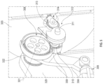
- FIG. 5 shows a detail view of a portion of the exemplary system 302 of FIG. 4 .
- the pinion 310 is mounted within pinion housing 309, which is coupled in a fixed position to the arm 304 and/or the proprotor frame 322. Accordingly, the pinion 310 is rotationally coupled to the proprotor frame 322 such that the pinion 310 moves with the proprotor frame 322 (e.g., as the proprotor frame 322 and proprotor 303 rotate about the rotation axis 301).
- the pinion 310 is also engaged with the gear 308.
- Rotation of the pinion housing 309 drives the pinion 310 around at least a portion of the gear 308, which causes the pinion 310 to rotate via the toothed engagement with the gear 308.
- the cam 312 is fixedly connected to the pinion 310, such as via the internal pin 311, such that the cam 312 rotates with the pinion 310.
- the cam 312 is also operatively coupled to a first end of the control rod 314, such that the control rod 314 translates relative to the internal pin 311 during at least a portion of the rotation of the cam 312.
- the control rod 314 is coupled at a second end to the blades of the proprotor (as will be described below) such that translation of the control rod 314 adjusts the pitch angle of the blades.
- the pinion 310 revolves around the gear 308, which rotates the cam 312 and translates the control rod 314, thereby adjusting the pitch angle of the blades of the proprotor 303.
- the system 302 mechanically links tilting the proprotor 303 with adjusting the pitch angle of the blades of the proprotor 303.
- the control rod 314 can be engaged with the cam 312 via a follower that follows the cam 312 as the cam 312 rotates.
- the follower can be, for example, a roller or a pin.
- the control rod 314 engages the cam 312 via a roller 313.
- the roller 313 travels along the outer surface of the cam 312 as the cam 312 rotates.
- the control rod 314 can be biased in compression against the cam 312, such as via a spring (not shown in figure).
- the cam profile controls the position of the control rod.
- the profile of the cam 312 can include one or more portions that cause translation of the control rod 314 and can include one or more portions do not cause the control rod 314 to translate.
- the cam 312 can have one or more spiral portions that cause translation of the control rod 314 and/or one or more circular portions that do not cause the control rod 314 to translate.
- the cam 312 includes a spiral profile that will cause the control rod 314 to continuously translate throughout the range of tilt of the proprotor.
- FIG. 6 shows another detail view of a portion of the exemplary system 302 of FIGs. 4 and 5 .
- FIG. 5 depicts the control rod 314 engaged with two sides of the outer surface of the cam 312 (e.g., in the corner area of the snail-shaped cam)
- FIG. 6 depicts the control rod 314 engaged with only one side of the outer surface of the cam 312.
- the position of the control rod 314 depicted in FIG. 6 compared to that of the control rod of FIG. 5 can be obtained by rotating the cam 312 in a clockwise direction such that the roller 313 moves in a counterclockwise direction as it follows the surface of the cam 312.
- the control rod 314 may translate toward or away from the internal pin 311 at the center of the cam 312. For instance, if the cam 312 rotates in a clockwise direction, as the roller 313 follows the spiral portion of the cam 312, the control rod 314 translates away from the internal pin 311. Opposite, if the cam 312 rotates in a counter-clockwise direction, the control rod 314 can translate towards the internal pin 311 as the roller 313 follows the spiral portion of the cam 312. As the roller 313 follows the circular portion of the cam 312, the control rod 314 may remain at a constant distance and not translate relative to the internal pin 311.
- the cam 312 can include a spiral profile for the first 210 degrees of rotation, with a circular profile for the remaining 150 degrees of rotation, such that the control rod 314 only translates away from the internal pin 311 during the first 210 degrees of rotation of the cam 312.
- the control rod 314 can be biased in compression against the cam 312 via a spring 315.
- FIG. 6 shows an example where the control rod 314 has a roller 313 engaged with an outer surface of the cam 312.
- Alternate configurations may have a different engagement between the control rod and cam.
- FIG. 7 shows a top perspective view of an exemplary system 402 that includes a control rod 414 with a pin 413 engaged with a track 411 of a cam 412. The pin 413 engages the track 411 of the cam 412 such that the cam 412 can both push and pull the pin 413 and the control rod as the cam 412 rotates.
- the system 402 can be used for system 202 of FIG. 3 . Similar to the systems discussed above, the system 402 connects a proprotor 403 to a portion of an aircraft (to a boom 401 as shown in FIG. 7 ). Distinct from the systems above, however, the system 402 includes a control rod 414 with a pin 413 that rides in a track. This configuration is more clearly visible the detailed pop-out of the cam 412, which shows the pin 413 of the control rod 414 engage with the track 411 in the cam 412. As the cam 412 rotates, such as by engagement with the pinion 410 rotating as it revolves around the gear 408, the pin 413 can follow the track 411, thereby translating the control rod 414.
- the gear 408 can be fixed in position relative to the fixed frame 420, which is fixedly mounted to the aircraft. For instance, as shown in FIG. 7 , the gear 408 is connected to the fixed frame 420.
- the pinion 410 can be rotatably mounted to the fixed frame 420, such that the pinion 410 is rotationally coupled to the proprotor frame 422 and moves with the proprotor frame 422.
- the track 411 can include a spiral portion and a circular portion. As the pin 413 follows spiral portion of the track 411, the control rod 414 can translate toward or away from a center of the cam 412. As the pin 413 follows a circular section of the track 411, however, the control rod 414 can remain at a constant distance and not translate relative to the center of the cam 412.
- the track 411 of the cam 412 can be a variety of geometries, based on the type of translation desired.
- the control rod 414 can be biased in compression or tension against the cam 312, such as via a spring (not shown in figure).
- FIG. 8 Another exemplary cam-control rod configuration is shown in FIG. 8 .
- the control rod 514 is held in tension.
- the system 502 can include a proprotor frame 522 rotatably mounted to a fixed frame 520 that is mounted to a portion of the aircraft (such as to the fuselage, wing, or a boom structure).
- the system 502 can be configured such that one or more actuators (not shown in figure) drive the proprotor frame 522 to rotate about the rotation axis 501 to tilt a proprotor mounted to the proprotor frame 522 between a vertical thrust position and a forward thrust position.
- the system 502 includes a control rod 514 that engages a cam 512, which rotates based on an engagement with a pinion 510 engaged with a gear 508.
- the gear 508 can be fixed in position relative to the fixed frame 520. For instance, as shown in FIG. 7 , the gear 508 is connected to the fixed frame 520.
- the cam 512 is fixedly connected to the pinion 510, such as via the shaft 516, so that the cam 512 rotates with the pinion 510.
- the pinion 510 can be rotatably mounted to the fixed frame 520, such as via a bearing mounting to rib 560, such that the pinion 510 is rotationally coupled to the proprotor frame 522 and moves with the proprotor frame 522.
- the pinion 510 revolves around the gear 508 as the proprotor frame 522 moves, which rotates the cam 512.
- the control rod 514 includes a clevis 515 and a follower 513, which is a roller in this example. As shown, the cam 512 is engaged with the follower 513 such that the follower 513 rolls along the cam 512 as it rotates. The follower 513 is rotatably attached to the clevis 515 of the control rod 514. The control rod 514 is in tension (a force is applied-such as via one or more springs-along axis 514 to the left in the view of FIG. 8 ) such that the follower 513 is forced against the cam 512. Thus, as the follower 513 rolls along the cam 512, the control rod 514 may translate along axis 505 (depending on the profile of the cam 512). As above, the cam 512 can have any suitable profile that for achieving the desired relationship between blade pitch and proprotor tilt.
- the clevis 515 includes a slot 536 that through which the shaft 516 may extend.
- the clevis 515 is separated from the shaft 516 by a bushing, which is shown more clearly in FIG. 9 , which shows a detail cutaway view of the bushing 519 and clevis 515 interface of the system 502 of FIG. 8 .
- the bushing 519 can include engagement surfaces 529 on the areas of the bushing 519 that engage with the clevis 515, with the engagement surfaces 529 shaped such that the clevis 515 is prevented from rotating, which in turn prevents the control rod attached to the clevis 515 (e.g., the control rod 514 shown in FIG. 8 ) from rotating. As shown in FIG.
- the engagement surfaces 529 of the bushings 519 are flat, which corresponds to flat surfaces of the clevis 515.
- these surfaces may be another shape, based on the shape of corresponding surfaces of the clevis 515.
- the engagement between the clevis 515 and the bushings 519 may involve circular, elliptical, or angled surfaces.
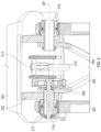
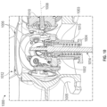
- FIG. 10 shows a cutaway detail view of an exemplary hub 1000 of a proprotor, showing an example of the coupling of a control rod 1014 with the blades 1012 of the proprotor, according to one or more examples of the disclosure.
- the hub 1000 can include an engine shaft 1004, a spring 1015, a bearing 1003, a plate 1002, a pitch plate 1005 and a number of links 1006.
- the blades 1012 are mounted to the hub 1000.
- each blade 1012 can include blade roots 1010 that connect to the links 1006.
- the control rod 1014 connects to the pitch plate 1005 and/or the plate 1002 of the hub 1000.
- the other end of the control rod 1014 can connect to a system configured to translate the control rod 1014 while tilting a proprotor, as discussed above.
- the engine shaft 1004 surrounds the spring 1015 and the bearing 1003 and connects to the plate 1002 that connects to the pitch plate 1005 engaged with the links 1006.
- the engine shaft 1004 connects to the engine (not shown in figure) of the hub 1000.
- the plate 1002 is constrained in rotation by a spline interface to the engine shaft 1004 such that the plate 1002 rotates with the engine shaft 1004.
- the control rod 1014 is prevented from rotating along with the plate 1002 via the bearing 1003.
- the pitch plate 1005 connects to the blade roots 1010 via links 1006.
- the links 1006 are dog-bone links, however other linkage types are contemplated, such as pitch links, etc.
- the spring 1015 can maintain the control rod 1014 in tension or compression. In the example of FIG. 10 , the spring 1015 maintains the control rod 1014 in tension by pressing the control rod 1014 against the pitch plate 1005.
- the plate 1002 and/or pitch plate 1005 translates, which causes the links 1006 to adjust the pitch angle of the blades 1012 by rotating each blade 1012 about a central axis 1008 of the blade 1012. Rotating each blade 1012 about the central axis 1008 adjusts the pitch angle of the blades 1012. Accordingly, translation of the control rod 1014 can adjust the pitch angle of the blades 1012 of the proprotor.
- adjusting the pitch of the blades of a proprotor based on the tilt of the proprotor can enable the propeller operational characteristics to be tuned to the different stages of flight, which can lead to greater efficiency that can result in less energy demand over the course of the flight.
- the relationship between blade pitch and proprotor tilt can be selected by selecting the desired cam profile (e.g., the profile of cam 214).
- a wide variety of relationships between blade pitch and proprotor tilt are achievable based on the selection of the cam profile.
- FIG. 11 is a graph that shows examples of some of these relationships.
- the graph of FIG. 11 shows blade pitch as a function of proprotor tilt angle.
- the proprotor tilt angle which is provided on the X-axis of the graph of FIG. 11 , is the angle of the rotational axis of the proprotor relative to a line that extends parallel to a longitudinal axis of the aircraft and intersects the rotational axis of the proprotor.
- the rotational axis of the proprotor is shown in the example of FIG.
- rotational axis 1101-A when the proprotor is in a forward flight position (rotational axis 1101-A is coincident with the line that extends parallel to the longitudinal axis 1103 of the aircraft and intersects the rotational axis of the proprotor) and rotational axis 1101-B when the proprotor is in a lift position.
- Zero degrees of tilt angle on the graph of FIG. 11 corresponds to the proprotor having a rotational axe that is parallel to the longitudinal axis 1103 of the aircraft-e.g., for providing forward thrust for forward flight, and ninety degrees of tilt angle corresponds to the proprotors providing vertical thrust, such as for vertical take-off and landing.
- the pitch of the blades which is provided on the Y-axis of the graph of FIG. 11 , can be defined as the angle between the chord of the blade and the plane of rotation and may be measured at a specific point along the length of the blade.
- FIG. 12 is a diagram showing an example of the definition of blade pitch.
- the blade 1208 (only one is shown for simplicity but it will be understood that each proprotor will include multiple blades) revolves about proprotor rotational shaft 1214 and is mounted such that it can rotate about a pitch axis 1206, enabling the pitch 1216 of the blade 1208 to be adjusted.
- the plane that contains the pitch axis 1206 and is traversed by the blade 1208 when the blade 1208 rotates can be referred to as the disc plane 1210.
- the pitch 1216 of the blade 1208 can be defined as the angle between the chord 1204 of the blade 1208 (a line joining the leading edge and trailing edge of the blade 1208) and a line 1202 lying within disc plane 1202 that is perpendicular to the pitch axis 1206.
- the pitch values shown in FIG. 11 are merely exemplary and it will be understood by a person of ordinary skill in the art that the pitch values will depend on the specific design of the blades and the location along the blades where the pitch is measured.
- the proprotor tilt values shown in FIG. 11 are merely exemplary and it will be understood by a person of ordinary skill in the art that a different range of proprotor tilt could be used, including a negative tilt angle associated with the proprotor being tilted somewhat downwardly.
- FIG. 11 includes four different lines 1102-1108 indicating four different relationships between blade pitch and proprotor tilt. Each line is associated with a different cam profile. Lines 1102, 1104, and 1106 have maximum blade pitches (maximums for the given line) at a zero proprotor tilt angle. This can be the blade pitch for forward flight in which the higher blade pitch can provide better efficiency at the relatively high airspeeds of forward flight.
- Line 1108 has a very low blade pitch at zero proprotor tilt. This could result in the blades creating a relatively high drag at high airspeeds, which can be useful to slow down the aircraft, such as for landing. This low blade pitch may also be useful for increasing the efficiency of the proprotor at low airspeeds, such as during a conventional (airplane style) take-off.
- the blade pitch quickly increases to a maximum so that the proprotor need only be tilted a relatively small amount to achieve the maximum blade pitch, which may be a desirable blade pitch for forward flight.
- the proprotor need only be tilted a small amount relative to the minimum tilt (e.g., zero tilt as shown, a small positive tilt, a small negative tilt, etc.) to achieve a more optimal blade pitch for the high speeds of forward flight.
- the minimum tilt e.g., zero tilt as shown, a small positive tilt, a small negative tilt, etc.
- Each line 1102-1108 shows the blade pitch decreasing to a minimum blade pitch (minimum for the given relationship) that is associated with a maximum proprotor tilt-tilt that may be used for vertical flight and hover.
- the minimum blade pitch can be optimal for the low air speed and high thrust requirements of vertical flight and hover.
- Lines 1104 and 1106 demonstrate that the minimum blade pitch need not be zero.
- the particular proprotor tilt angle at which the blade pitch minimum is reached can be selected based on the cam profile, as demonstrated by the different locations of this point for the various relationships (e.g., point 1110).
- Each relationship 1102-1108 is achieved by a different cam profile.
- Cam profiles can include multiple regions having different shaped to achieve the changes in relationship between the blade pitch and proprotor tilt of the various lines 1102-1108.
- line 1102 can be achieved by a cam profile that includes a spiral section that corresponds to the range of zero degrees proprotor tilt to the proprotor tilt angle of point 1110. The spiral section (continuously changing radius) transitions to a circular section (constant radius) that provides for the unchanging blade pitch associated with proprotor tilt angles past point 1110.
- Line 1106 can be achieved by a first spiral section, followed by a second spiral section that has a different rate of change of the radius than the first spiral section, followed by a circular section.
- Line 1104 can be achieved by a cam profile that has continuously varying rates of change of radius.
- FIG. 11 The relationships shown in FIG. 11 are merely examples illustrating that many different relationships can be achieved by the appropriate selection of the cam profile. A person of ordinary skill in the art will understand that the desired relationship between blade pitch and proprotor tilt can be achieved by the appropriate cam profile design.
- any of the systems described above, such as system 202, system 302, system 402, system 502, and aircraft 100 can include a damper, as shown in the exemplary system 1302 of FIG. 13 , for limiting a rate of tilt of the proprotor, such as in the event of actuator failure.
- the damper 1325 of system 1302 is connected between the boom 1305 of an aircraft, such as aircraft 100 of FIGS. 1 and 2 , and the proprotor frame 1322, to which a proprotor (not shown) mounts.
- the damper 1325 can be housed within an outer shell of the boom 1305.
- the boom 1305 can include a rib 1350, and the actuator 1306 and the damper 1325 can be positioned on opposite sides of the rib 1350.
- the proprotor frame 1322 is titltably connected to the fixed frame 1320 such that the proprotor frame 1322 (and the proprotor) can tilt about rotation axis 1301.
- the actuator 1306 is connected to the proprotor frame 1322 and drives the tilting of the proprotor about the rotation axis 1301.
- the actuator 1305 can be a linear actuator.
- the actuator can be a rotary actuator, as shown in the exemplary system 1402 of FIG. 14 .
- the system 1402 is otherwise similar to system 1302 of FIG. 13 in that it includes a damper 1425 connected between a boom 1405 of an aircraft and a proprotor frame 1422, which is tiltably connected to the fixed frame 1420 such that the proprotor frame 1422 (and the proprotor) can tilt about the rotation axis 1401.
- System 1402 includes a rotary actuator 1406 connected to the proprotor frame 1422 that drives the tilting of the proprotor about the rotation axis 1401.
- the rotary actuator 1406 includes an electric motor connected to a gear train that drives a worm gear. The worm gear drives a gear to rotate about the rotation axis 1401, which tilts the proprotor.
- the system 1302 could include a second (redundant) actuator that is also connected to the proprotor frame 1322 such that if the first actuator 1306 becomes disconnected, the second actuator can nonetheless control the tilting of the proprotor about the rotation axis 1301.
- adding a second actuator may complicate the system 1302, increase cost, and add more weight to the aircraft.
- the system 1302 instead includes a damper mechanism such as damper 1325.
- the damper 1325 can include a balanced hydraulic or pneumatic cylinder, which as is known in the art includes a piston that slides within a cylinder, the piston including a plurality of apertures through which fluid flows as the piston moves within the cylinder.
- the damper 1325 is a passive damper configured to apply a force (a hydraulic or pneumatic force) to the proprotor frame 1322 (and proprotor) only when the tilt angle of the proprotor is being adjusted (i.e., no bias is applied when the proprotor is at rest).
- the system 1302 may include one or more redundant actuators as well as a damper mechanism such as damper 1325.
- the damper 1325 can be configured to limit the rate of change of the tilt angle of the proprotor frame 1322 in both tilt directions.
- the damper 1325 can be positioned such that a force vector of the damper 1325 can extend beneath the tilt axis, such as tilt axis 118 of FIG. 2 .
- the damper 1325 can be configured to limit the rate of change of the tilt angle of the proprotor to a predetermined threshold value in the event that the actuator 1305 becomes disconnected from the proprotor frame 1322.
- controlling an aircraft that includes one or more dampers can include receiving a command at a controller to adjust a tilt angle of a tiltable proprotor that is tiltable between a lift position for providing lift for the aircraft and a forward flight position for providing forward propulsion for the aircraft, and controlling at least one actuator to adjusting the tilt angle of the tiltable proprotor according to the command, wherein at least one passive damper is connected to the tiltable proprotor to limit a rate of change of the tilt angle of the tiltable proprotor
- any of the systems described above can include a tilt rotor lock mechanism, as shown in the exemplary system 1502 of FIG. 15 , which shows a side view of the system 1502 in a first configuration, according to one or more examples of the disclosure.
- the system 1502 can be implemented in an aircraft with a tiltable proprotor instead of, or in addition to, redundant actuators and/or a damper mechanism, and can lock the tilt of the proprotor in place.
- the system 1502 is positioned between a boom 1505 and proprotor 1503 of an aircraft, and can include a tension spring 1545 connected to a pulley 1540 via connector 1560, with the pulley 1540 also connected via connector 1542 to a pawl 1552.
- the pawl 1552 can be selectively engaged with a sector gear 1550 based on movement of the pulley 1540, with the pawl 1552 configured to move towards the sector gear 1550 as the pulley 1540 moves away from the actuator 1506.
- the pulley 1540 is coupled to the actuator 1506 in normal operation.
- FIG. 15 shows the pawl 1552 not engaged with the sector gear 1550 and the pulley 1540 located adjacent to the actuator 1506
- FIG. 16 shows the pawl 1552 engaged with the sector gear 1550 and the pulley 1540 no longer located adjacent to the actuator 1506.
- FIG. 17 shows a front view of the exemplary system of FIG. 15 , according to one or more examples of the disclosure.
- the sector gear 1550 can be a ratchet with ridges that contact the pawl 1552.
- FIG. 18A shows an exemplary ratchet configuration 1602, according to one or more examples of the disclosure.
- the ratchet configuration 1602 includes a sector gear 1650 that has a number of ridges 1653 that have a sloped side and a straighter side.
- the pawl 1652 rides over the sloped sides but catches on the straighter sides.
- the proprotor will be ablet to tilt in a first direction (e.g., permitted to tilt counterclockwise in the illustrated configuration) but not a second direction (e.g., not permitted to tilt clockwise in the illustrated configuration).
- a ratchet mechanism could also be used with any of the damper configurations described above to provide a slower rate of tilt in the ratcheting direction.
- FIG. 8B illustrates an exemplary lock configuration 1604 that has a sector gear 1650 that has a number of ridges 1655 that have two straight sides and a locking mechanism 1654 that engages the ridges 1655.
- the locking mechanism 1654 When the locking mechanism 1654 is forced against the gear sector 1650, the locking mechanism will engage with the ridges 1655. The locking mechanism 1654 will be unable to ride past the ridges 1655 in either direction because of their straight sides, locking the sector gear 1650 (and, thereby, the proprotor) in position.
- described herein are systems and methods for mechanically linking the tilt of a proprotor of an aircraft with the pitch of blades of the proprotor.
- the systems enable blade pitch to be tailored to the different operational regimes of the proprotor while avoiding the need for dedicated blade pitch adjustment actuators and the cost, weight, and failure points associated with such dedicated blade adjustment actuators.
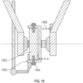
- FIG. 19 illustrates an alternative spring configuration and a feature for providing a "midlife" check capability to ensure that the pawl mechanism is not jammed.
- the mechanism 1900 can be bolted to the rod end fitting 1902 using one or more bolts 1904 or other removable attachment features.
- the bolts 1904 can be removed during routine maintenance to verify that the pawl engages the sector gear.
- the tilt actuator can then be driven to change the tilt of the rotor for some duration to confirm that the pawl engaged.
- the illustrated embodiment includes a torsion spring 1906 in place of a tension spring and cable, which can provide a weight savings, decrease required volume, and increase ruggedness.
Landscapes
- Engineering & Computer Science (AREA)
- Aviation & Aerospace Engineering (AREA)
- Mechanical Engineering (AREA)
- Transmission Devices (AREA)
Description
- This application claims the benefit of
U.S. Provisional Application No. 63/378,536, filed October 6, 2022 U.S. Provisional Application No. 63/378,680, filed October 7, 2022 U.S. Application No. 18/098,417, filed January 18, 2023 - The present disclosure relates generally to aircraft, and more specifically, to aircraft with tiltable proprotors.
- Vertical take-off and landing (VTOL) aircraft are aircraft that can take-off and land vertically and hover. To take-off and land vertically and hover, VTOL aircraft can include one or more proprotors that can be tilted between a position for providing vertical thrust for take-off and landing and hover and a position for providing forward thrust for forward flight. VTOL aircraft can include wings like conventional fixed-wing aircraft that provide lift during forward flight.
- The pitch of the blades of a proprotor affect the efficiency and thrust of the proprotor. It is often desirable to adjust a pitch of the blades for different operational regimes. For example, when the proprotors are positioned for providing vertical thrust, it may be desirable to have the blades at a pitch that maximizes thrust, but when the proprotors are positioned for providing forward thrust during cruise, it may be desirable to have the blades at a pitch that provides greater efficiency. Blade pitch control actuators may be used to enable adjustment of blade pitch during flight.
US 10,640,207 B2 US 3,514,052 A relates to control system for an aircraft having laterally offset rotors which are tiltable between vertical positions for helicopter mode of operation and horizontal positions for propeller mode of operation and which has roll, pitch and yaw control in both modes of operation with the yaw control in the helicopter mode constituting tilting the rotor pods in opposite directions while applying differential longitudinal cyclic pitch to the rotors and washing out the cyclic pitch in response to increased pod tilting. - In a first aspect, a system for tilting a proprotor of an aircraft according to claim 1 is provided. In a second aspect, a method for operating a VTOL aircraft according to claim 16 is provided. Preferred embodiments are provided in the dependent claims.
- A proprotor tilt and blade pitch adjustment system for a VTOL aircraft mechanically links the pitch of the blades of a proprotor of the aircraft to the tilt angle of the proprotor such that the blade pitch can adjust as the proprotor tilt angle changes. By mechanically linking blade pitch adjustment with proprotor tilting, blade pitch can be coordinated with proprotor tilt position for achieving more efficient proprotor performance without requiring a dedicated blade pitch adjustment actuator, which can save power, weight, and cost.
- The proprotor is tiltably mounted to the aircraft and includes one or more actuators that tilt the proprotor. At least one fixed gear is fixed in position relative to the aircraft. A pinion is rotatably connected to a tiltable frame to which the proprotor is mounted and is engaged with the fixed gear such that as the pinion gear moves with the tiltable frame, the pinion revolves around the fixed gear, which causes the pinion to rotate. A cam is connected to the pinion such that the cam rotates along with the pinion. A control rod is operatively coupled to the cam such that as the cam rotates the control rod follows the profile of the cam, which causes the control rod to translate depending on the profile. The control rod is operatively connected to the blades of the proprotor such that as the control rod translates, the pitch of the blades of the proprotor are adjusted. Thus, as the proprotor is tilted about the tilt axis, the pitch of the blades of the proprotor can be adjusted. Accordingly, the system is configured to mechanically link tilting the proprotor and adjusting the pitch of the blades of the proprotor.
- It will be appreciated that any of the variations, aspects, features, and options described in view of the systems apply equally to the methods and vice versa. It will also be clear that any one or more of the above variations, aspects, features, and options can be combined.
- The invention will now be described, by way of example only, with reference to the accompanying drawings, in which:
-
FIG. 1 shows an aircraft in a forward flight configuration, according to one or more examples of the disclosure; -
FIG. 2 is a perspective view of the aircraft ofFIG. 1 illustrating the proprotor positions in the lift and forward flight configurations, according to one or more examples of the disclosure; -
FIG. 3 shows a side view of a portion of an aircraft with an exemplary system, according to one or more examples of the disclosure; -
FIG. 4 shows a detail view of an exemplary system, according to one or more examples of the disclosure; -
FIG. 5 shows a detail view of a portion of the exemplary system ofFIG. 4 , according to one or more examples of the disclosure; -
FIG. 6 shows another detail view of a portion of the exemplary system ofFIG. 4 , according to one or more examples of the disclosure; -
FIG. 7 shows a top perspective view and a detail view of an exemplary system, according to one or more examples of the disclosure; -
FIG. 8 shows a detail view of an exemplary system with a control rod in tension, according to one or more examples of the disclosure; -
FIG. 9 shows a detail cutaway view of the bushing and cam interface of the exemplary system ofFIG. 8 , according to one or more examples of the disclosure; -
FIG. 10 shows a cutaway detail view of an exemplary hub of a proprotor, according to one or more examples of the disclosure; -
FIG. 11 shows a graph of examples of blade pitch as a function of proprotor tilt angle; -
FIG. 12 is a diagram illustrating blade pitch angle; -
FIG. 13 shows a detail view of an exemplary system, according to one or more examples of the disclosure; -
FIG. 14 shows a detail view of an exemplary system, according to one or more examples of the disclosure; -
FIG. 15 shows a side view of an exemplary system in a first configuration, according to one or more examples of the disclosure; -
FIG. 16 shows the exemplary system ofFIG. 15 in a second configuration, according to one or more examples of the disclosure; -
FIG. 17 shows a front view of the exemplary system ofFIG. 15 , according to one or more examples of the disclosure; -
FIG. 18A shows an exemplary ratchet configuration andFIG. 18B shows an exemplary lock configuration for locking a proprotor in at least one direction; and -
FIG. 19 shows a front view of an exemplary system, according to one or more examples of the disclosure. - In the following description of the various examples, reference is made to the accompanying drawings, in which are shown, by way of illustration, specific examples that can be practiced. The description is presented to enable one of ordinary skill in the art to make and use the invention and is provided in the context of a patent application and its requirements. Various modifications to the described examples will be readily apparent to those persons skilled in the art and the generic principles herein may be applied to other examples. Thus, the present invention is not intended to be limited to the examples shown but is defined by the appended claims.
- Described herein are systems and methods for mechanically coupling adjustment of the pitch of the blades of the proprotor with the tilting of a proprotor. Coupling blade pitch to the tilt of the proprotor can enable the operational characteristics of the proprotor to be tuned to the different stages of flight, which can lead to greater efficiency that can result in less energy demand over the course of the flight. The systems and methods described herein enable the blade pitch to be tailored to the different operational regimes of the proprotor while avoiding the need for dedicated blade pitch adjustment actuators. Such dedicated blade pitch adjustment actuators and their associated mounting and wiring systems can add significant weight and cost to the aircraft and create another point of failure. By eliminating the need for such dedicated blade pitch adjustment actuators, the systems and methods described herein can achieve blade pitch adjustment while avoiding the increased weight, cost, and greater points of failure associated with the dedicated blade pitch adjustment actuators.
- The system includes a first frame for mounting to a portion of the aircraft, such as the boom or wing of the aircraft, and a second frame to which the proprotor can be mounted. The second frame is tiltably mounted to the first frame at a rotation axis. The second frame is tilted relative to the first frame by at least one actuator, such as a linear actuator that is connected to the second frame eccentrically from the rotation axis. The system includes a first gear located on the rotation axis and fixed in position relative to the first frame and a pinion that moves with the second frame and is engaged with the first gear. As the pinion moves with the second frame, (e.g., along with the second frame as it rotates about the rotation axis) the pinion revolves around at least a portion of the first gear, thereby causing the pinion to rotate. The system includes a cam fixedly connected to the pinion such that the cam rotates with as the pinion rotates. A control rod operatively couples with the cam such that the translational position of the control rod is controlled by the cam. Depending on the cam profile and cam rotational position, the cam can cause the control rod to translate. The control rod is coupled at an opposite end to the blades of the proprotor in such a way that translation of the control rod changes the pitch of the blades. As the proprotor tilts about the tilt axis, the engagement between the first gear and the pinion causes the pinion to rotate, thereby rotating the cam and potentially translating the control rod (depending on the cam profile), which alters the pitch of the blades of the proprotor. Accordingly, the system can adjust the pitch of the blades as the proprotor rotates about the rotation axis.
- As used herein, the singular forms "a," "an," and "the" used in the following description are intended to include the plural forms as well unless the context clearly indicates otherwise. It is to be understood that the term "and/or" as used herein refers to and encompasses any and all possible combinations of one or more of the associated listed items. It is further to be understood that the terms "includes," "including," "comprises," and/or "comprising," when used herein, specify the presence of stated features, integers, steps, operations, elements, components, and/or units but do not preclude the presence or addition of one or more other features, integers, steps, operations, elements, components, units, and/or groups thereof.
- As used herein, the term "proprotor" refers to a variable tilt propeller in which the direction of thrust of the propeller can be changed by changing the tilt angle of the propeller. For example, the tilt angle can be changed from an angle that provides at least some degree of vertical thrust, such as for vertical take-off and landing, to an angle that provides at least some degree of horizontal thrust, such as for forward flight. As used herein, a proprotor lift configuration refers to any proprotor orientation in which the proprotor thrust is providing primarily lift to the aircraft and proprotor forward flight configuration refers to any proprotor orientation in which the proprotor thrust is providing primarily forward thrust to the aircraft.
- As used herein, "vertical take-off and landing" ("VTOL") refers to the capability of an aircraft to move substantially vertically without lift being provided solely by wings of the aircraft. While this term encompasses directly vertical take-off and landing (i.e., vertical movement without any horizontal movement), it also encompasses vertical movement in combination with horizontal movement. It will be understood by a person having ordinary skill in the art that a VTOL aircraft may be capable of non-vertical take-off and landing. For example, a winged VTOL, such as various examples described herein, can take-off and land in a traditional airplane manner utilizing the lift provided by its wings at suitable airspeeds.
-
FIG. 1 shows anaircraft 100 in a forward flight configuration. Theaircraft 100 includes afuselage 102,wings 104 mounted to thefuselage 102, and one or morerear stabilizers 106 mounted to the rear of thefuselage 102. Theaircraft 100 can be a vertical take-off and landing (VTOL) aircraft, and may be a passenger aircraft. A plurality ofrotors 112 are mounted to thewings 104 and are configured to provide lift, such as for take-off and landing. A plurality ofproprotors 114 are mounted to thewings 104 and are tiltable between lift configurations in which they provide a portion of the lift required for vertical take-off and landing and hovering, and forward flight configurations (as shown inFIG. 1 ) in which they provide forward thrust to theaircraft 100 for horizontal flight. - During take-off and landing, the
proprotors 114 are tilted to lift configurations in which their thrust is directed upward for providing lift. For forward flight, theproprotors 114 tilt from their lift configurations to their forward flight configurations in which their thrust is directed forward for providing forward propulsion. In other words, the pitch of theproprotors 114 is varied from a tilt angle in which the proprotor provides lift for take-off and landing (and, optionally, hover) to a tilt angle in which the proprotor provides forward thrust to theaircraft 100 for forward flight. Theproprotors 114 can each be tilted by one or more actuators. The actuator(s) can be electrically powered. Optionally, each proprotor has a single actuator for adjusting its tilt. According to various embodiments, theaircraft 100 can include one or more damper mechanisms connected to each tiltable proprotor configured to limit a rate of change of the tilt angle of the tiltable proprotor, such as in the event that the actuator becomes disconnected or otherwise fails. - When the
aircraft 100 is in full forward flight, lift may be provided entirely by thewings 104, and therotors 112 may be shut-off. Theblades 120 of therotors 112 may be locked in low drags positions for aircraft cruising. In some embodiments, therotors 112 each have twoblades 120 that are locked in minimum drag positions for cruising in which one blade is directly in front of the other blade as illustrated inFIG. 1 . In some embodiments, therotors 112 have more than two blades. In some embodiments, theproprotors 114 includemore blades 116 than therotors 112. For example, as illustrated inFIG. 1 , therotors 112 may each include two blades and theproprotors 114 may each include five blades. According to various embodiments, theproprotors 114 can have from 2 to 5 blades. - According to various embodiments, the aircraft includes only one
wing 104 on each side of the fuselage 102 (or a single wing that extends across the entire aircraft) and at least a portion of therotors 112 are located rearward of thewings 104 and at least a portion of theproprotors 114 are located forward of thewings 104. In some embodiments, all of therotors 112 are located rearward of thewings 104 and all of the proprotors are located forward of thewings 104. According to some embodiments, allrotors 112 andproprotors 114 are mounted to the wings-i.e., no rotors or proprotors are mounted to the fuselage. According to various embodiments, therotors 112 are all located rearwardly of thewings 104 and theproprotors 114 are all located forward of thewings 104. According to some embodiments, allrotors 112 andproprotors 114 are positioned inwardly of thewing tips 109. - According to various embodiments, the
rotors 112 andproprotors 114 are mounted to thewings 104 bybooms 122. Thebooms 122 may be mounted beneath thewings 104, on top of the wings, and/or may be integrated into the wing profile. According to various embodiments, onerotor 112 and one proprotor 114 are mounted to eachboom 122. Therotor 112 may be mounted at a rear end of theboom 122 and aproprotor 114 may be mounted at a front end of theboom 122. In some embodiments, therotor 112 is mounted in a fixed position on theboom 122. In some embodiments, theproprotor 114 is mounted to a front end of theboom 122 via a hinge or other system. Theproprotor 114 may be mounted to theboom 122 such that theproprotor 114 is aligned with the body of theboom 122 when in its forward flight configuration, forming a continuous extension of the front end of theboom 122 that minimizes drag for forward flight. - The aircraft is operated during take-off and landing by positioning the proprotors in lift configurations and providing the required lift to the aircraft via the combined lift provided by the rotors and proprotors. According to various embodiments, during take-off and landing and/or hover, the proprotors can be maintained in predetermined lift configurations that can be the same across all proprotors or different for different proprotors. According to various embodiments, the tilt of at least some of the proprotors can be actively adjusted during take-off and landing and/or hover to provide the required stability and/or maneuvering. As discussed further below, the pitches of the blades of the proprotors (also referred to herein as the pitch angle and angle of attack) are mechanically linked to the tilt of the proprotors such that the blade pitch is coordinated with the proprotor tilt, such as to achieve maximum thrust when the proprotor is in the lift configuration and to achieve increased efficiency when the proprotor is in the forward flight configuration.
- According to various embodiments, each rotor and/or each proprotor can be individually controlled by the flight controller according to the various operational degrees of freedom. According to various embodiments, the only degree of freedom of the rotor is the rotational speed of the rotor. According to various embodiments, the degrees of freedom of at least a portion of the proprotors includes the rotational speed of the proprotors, and the degree of tilt of the proprotors (combined with the blade pitch of the proprotors). According to various embodiments, any of these degrees of freedom can be actively controlled by the flight controller (either autonomously or in response to pilot commands) during take-off and landing in order to provide the appropriate stability and maneuvering.
- Once the aircraft has achieved sufficient altitude to commence forward flight, the proprotors begin tilting forward toward their forward flight configurations such that their thrust provides a combination of lift and thrust, with a decreasing proportion of lift as the proprotors are tilted further toward their forward flight configurations. The pitch angle of the blades can be adjusted as the proprotors tilt forward toward their forward flight configurations. For instance, in the forward flight configuration, the blades of the proprotor can be at a pitch angle that results in less drag relative to a pitch angle of the blades when in the lift configuration. The rotors can remain active during at least a portion of the period in which the proprotors are tilted forward to continue to provide rotor-based lift. At any point after the forward airspeed is high enough that the wings provide sufficient lift to maintain the aircraft's altitude, the rotors can be deactivated.
- The tilt of at least some of the proprotors can be actively controlled to provide additional stability and/or maneuverability control during cruising. In some embodiments, the tilt of at least some of the proprotors is actively controlled during take-off and landing and/or hover. In some embodiments, the tilt of the proprotors is fixed (i.e., non-varying) during cruise. According to some embodiments, the tilt of the outermost proprotors can be actively and independently controlled during vertical take-off and landing and/or hover to provide yawing moments as needed. The range of tilt angle of the tiltable proprotor(s) is at least 90 degrees, such that the proprotors can tilt between the forward flight configuration and the lift configuration.
-
FIG. 2 is a perspective view of theaircraft 100 ofFIG. 1 illustrating the proprotor positions in the lift and forward flight configurations, according to one or more examples of the disclosure. Theproprotors 114 can tilt about thetilt axis 118 that is perpendicular to the forward direction of the aircraft. For forward flight, the proprotors tilt from the lift configuration, which provides vertical thrust, to a forward flight configuration, which provides forward thrust. - As described further below, the
aircraft 100 can include a system to tilt theproprotors 114 between the lift configuration and the forward flight configuration. The system can mechanically link adjustment of the pitch angle of the blades of theproprotor 114 to the adjustment of the tilt of theproprotors 114. -
FIG. 3 illustrates anexemplary system 202 for coupling tilting a proprotor with adjusting the pitch angle of blades of the proprotor. Thesystem 202 is configured such that the pitch angle of the blades of the proprotor can correspond with the tilt position of the proprotor without requiring independent systems for tilting the proprotor and adjusting the pitch angle of the blades. Accordingly, thesystem 202 reduces the complexity and cost of the aircraft. - The
system 202 rotatably couples aproprotor 203 to aboom 205 of an aircraft, proprotor 114 to boom 122 ofaircraft 100. Thesystem 202 includes a fixedframe 220 for mounting to the aircraft (e.g., theproprotor 203 can be connected to aboom 205 via a bracket 236 of the fixed frame 220) and aproprotor frame 222 to which theproprotor 203 mounts. Theproprotor frame 222 can be tiltably connected to the fixedframe 220 at a joint 212. - The
system 202 can include one or more arm(s) 204 connected to theproprotor frame 222. Alinear actuator 206 can be connected to the arm(s) 204 tilt theproprotor 203 about the joint 213. Theactuator 206 can be, for example, a ball screw actuator or a pneumatic actuator. Alternatively, rotary actuator, such as a stepper motor or a servomotor, can be mounted at the joint or can drive a gear train that has an output gear located at the joint or engaged with a gear located at the joint. - The
system 202 includes acam 214 that can rotate in correspondence with tilting of theproprotor 203. A control rod (discussed further below) is operatively coupled with thecam 214 such that the control rod can translate when thecam 214 rotates. The control rod is coupled at its opposite end to theblades 250 of theproprotor 203 such that translation of the control rod adjusts the pitch angle of theblades 250 of theproprotor 203. Accordingly, thesystem 202 couples the pitch angle of theblades 250 of theproprotor 203 to the tilt of theproprotor 203. During operation, a control system of the aircraft can send a proprotor tilt adjustment command to theactuator 206. Theactuator 206 may extend or retracted, causing the proprotor to increase or decrease its degree of tilt. As the proprotor tilt changes, thecam 214 rotates. This, in turn, can cause the control rod to translate, which adjusts the pitch of theblades 250. -
FIG. 4 shows a detail view of anexemplary system 302 for mechanically linking tilting a proprotor of an aircraft between a vertical thrust position and a forward thrust position with adjusting the pitch angle of blades of the proprotor. Thesystem 302 can be used forsystem 202 ofFIG. 3 . Thesystem 302 includes a fixedframe 320 for mounting to a portion of a VTOL aircraft (such as to the fuselage, wing, or a boom structure), and a proprotor frame 322 for mounting theproprotor 303 that is rotatably mounted to the fixedframe 320 at arotation axis 301. Thesystem 302 includes agear 308, a pinion (not shown in figure), acam 312, acontrol rod 314, and a pair ofarms 304. - As shown in
FIG. 4 , thegear 308 is located along therotation axis 301. Thegear 308 can be fixed in position relative to the fixedframe 320. For instance, as shown inFIG. 4 , thegear 308 is connected to an internal pin 318 that attaches to the fixedframe 320. One or more of theshafts 316 can surround an internal pin 318, which is shown clearly by the cutaway view of theleft shaft 316 ofFIG. 4 . A set ofbearings 317 is located between eachshaft 316 and the fixedframe 320 such that theshafts 316 are rotatably mounted to the fixedframe 320. - The proximal end of the
arms 304 can engage with the proprotor frame 322. The engagement between thearms 304 and the proprotor frame 322 can be a fixed connection, such as by bolting or welding thearms 304 to the proprotor frame 322. Optionally, both thearms 304 and the proprotor frame 322 can be fixedly connected to theshafts 316. The distal end of thearms 304 can connect to one or more actuators 306 (seeFIG. 5 ) that drive thearms 304 to rotate about therotation axis 301. As theactuator 306 drives thearms 304, theproprotor 303 is rotated about therotation axis 301. - The engagement between the
gear 308, pinion,cam 312 andcontrol rod 314 is shown more clearly inFIG. 5 , which shows a detail view of a portion of theexemplary system 302 ofFIG. 4 . Thepinion 310 is mounted within pinion housing 309, which is coupled in a fixed position to thearm 304 and/or the proprotor frame 322. Accordingly, thepinion 310 is rotationally coupled to the proprotor frame 322 such that thepinion 310 moves with the proprotor frame 322 (e.g., as the proprotor frame 322 andproprotor 303 rotate about the rotation axis 301). Thepinion 310 is also engaged with thegear 308. Rotation of the pinion housing 309 drives thepinion 310 around at least a portion of thegear 308, which causes thepinion 310 to rotate via the toothed engagement with thegear 308. - The
cam 312 is fixedly connected to thepinion 310, such as via theinternal pin 311, such that thecam 312 rotates with thepinion 310. Thecam 312 is also operatively coupled to a first end of thecontrol rod 314, such that thecontrol rod 314 translates relative to theinternal pin 311 during at least a portion of the rotation of thecam 312. Thecontrol rod 314 is coupled at a second end to the blades of the proprotor (as will be described below) such that translation of thecontrol rod 314 adjusts the pitch angle of the blades. - As the proprotor frame 322 rotates about the rotation axis 301 (e.g., to tilt the proprotor 303), the
pinion 310 revolves around thegear 308, which rotates thecam 312 and translates thecontrol rod 314, thereby adjusting the pitch angle of the blades of theproprotor 303. Accordingly, thesystem 302 mechanically links tilting theproprotor 303 with adjusting the pitch angle of the blades of theproprotor 303. - The
control rod 314 can be engaged with thecam 312 via a follower that follows thecam 312 as thecam 312 rotates. The follower can be, for example, a roller or a pin. As shown inFIG. 5 , thecontrol rod 314 engages thecam 312 via aroller 313. Theroller 313 travels along the outer surface of thecam 312 as thecam 312 rotates. To remain engaged with the outer surface of thecam 312, thecontrol rod 314 can be biased in compression against thecam 312, such as via a spring (not shown in figure). - The cam profile (e.g., shape of its outer surface that the control rod follows) controls the position of the control rod. The profile of the
cam 312 can include one or more portions that cause translation of thecontrol rod 314 and can include one or more portions do not cause thecontrol rod 314 to translate. For example, thecam 312 can have one or more spiral portions that cause translation of thecontrol rod 314 and/or one or more circular portions that do not cause thecontrol rod 314 to translate. In the example shown inFIG. 5 , thecam 312 includes a spiral profile that will cause thecontrol rod 314 to continuously translate throughout the range of tilt of the proprotor. -
FIG. 6 shows another detail view of a portion of theexemplary system 302 ofFIGs. 4 and5 . WhereasFIG. 5 depicts thecontrol rod 314 engaged with two sides of the outer surface of the cam 312 (e.g., in the corner area of the snail-shaped cam),FIG. 6 depicts thecontrol rod 314 engaged with only one side of the outer surface of thecam 312. The position of thecontrol rod 314 depicted inFIG. 6 compared to that of the control rod ofFIG. 5 can be obtained by rotating thecam 312 in a clockwise direction such that theroller 313 moves in a counterclockwise direction as it follows the surface of thecam 312. - As the
roller 313 follows the spiral portion of thecam 312, thecontrol rod 314 may translate toward or away from theinternal pin 311 at the center of thecam 312. For instance, if thecam 312 rotates in a clockwise direction, as theroller 313 follows the spiral portion of thecam 312, thecontrol rod 314 translates away from theinternal pin 311. Opposite, if thecam 312 rotates in a counter-clockwise direction, thecontrol rod 314 can translate towards theinternal pin 311 as theroller 313 follows the spiral portion of thecam 312. As theroller 313 follows the circular portion of thecam 312, thecontrol rod 314 may remain at a constant distance and not translate relative to theinternal pin 311. For example, thecam 312 can include a spiral profile for the first 210 degrees of rotation, with a circular profile for the remaining 150 degrees of rotation, such that thecontrol rod 314 only translates away from theinternal pin 311 during the first 210 degrees of rotation of thecam 312. As noted above, thecontrol rod 314 can be biased in compression against thecam 312 via aspring 315. -
FIG. 6 shows an example where thecontrol rod 314 has aroller 313 engaged with an outer surface of thecam 312. Alternate configurations may have a different engagement between the control rod and cam. For instance,FIG. 7 shows a top perspective view of anexemplary system 402 that includes a control rod 414 with apin 413 engaged with atrack 411 of acam 412. Thepin 413 engages thetrack 411 of thecam 412 such that thecam 412 can both push and pull thepin 413 and the control rod as thecam 412 rotates. - The
system 402 can be used forsystem 202 ofFIG. 3 . Similar to the systems discussed above, thesystem 402 connects aproprotor 403 to a portion of an aircraft (to a boom 401 as shown inFIG. 7 ). Distinct from the systems above, however, thesystem 402 includes a control rod 414 with apin 413 that rides in a track. This configuration is more clearly visible the detailed pop-out of thecam 412, which shows thepin 413 of the control rod 414 engage with thetrack 411 in thecam 412. As thecam 412 rotates, such as by engagement with thepinion 410 rotating as it revolves around thegear 408, thepin 413 can follow thetrack 411, thereby translating the control rod 414. - The
gear 408 can be fixed in position relative to the fixedframe 420, which is fixedly mounted to the aircraft. For instance, as shown inFIG. 7 , thegear 408 is connected to the fixedframe 420. Thepinion 410 can be rotatably mounted to the fixedframe 420, such that thepinion 410 is rotationally coupled to theproprotor frame 422 and moves with theproprotor frame 422. - The
track 411 can include a spiral portion and a circular portion. As thepin 413 follows spiral portion of thetrack 411, the control rod 414 can translate toward or away from a center of thecam 412. As thepin 413 follows a circular section of thetrack 411, however, the control rod 414 can remain at a constant distance and not translate relative to the center of thecam 412. Optionally, thetrack 411 of thecam 412 can be a variety of geometries, based on the type of translation desired. To remain engaged with thetrack 411, the control rod 414 can be biased in compression or tension against thecam 312, such as via a spring (not shown in figure). - Another exemplary cam-control rod configuration is shown in
FIG. 8 . Unlikesystem 302, insystem 502 thecontrol rod 514 is held in tension. Similar to the systems described above, thesystem 502 can include aproprotor frame 522 rotatably mounted to a fixedframe 520 that is mounted to a portion of the aircraft (such as to the fuselage, wing, or a boom structure). Thesystem 502 can be configured such that one or more actuators (not shown in figure) drive theproprotor frame 522 to rotate about therotation axis 501 to tilt a proprotor mounted to theproprotor frame 522 between a vertical thrust position and a forward thrust position. - Similar to the systems described above, the
system 502 includes acontrol rod 514 that engages acam 512, which rotates based on an engagement with apinion 510 engaged with agear 508. Thegear 508 can be fixed in position relative to the fixedframe 520. For instance, as shown inFIG. 7 , thegear 508 is connected to the fixedframe 520. Thecam 512 is fixedly connected to thepinion 510, such as via theshaft 516, so that thecam 512 rotates with thepinion 510. Thepinion 510 can be rotatably mounted to the fixedframe 520, such as via a bearing mounting torib 560, such that thepinion 510 is rotationally coupled to theproprotor frame 522 and moves with theproprotor frame 522. Thepinion 510 revolves around thegear 508 as theproprotor frame 522 moves, which rotates thecam 512. - The
control rod 514 includes aclevis 515 and afollower 513, which is a roller in this example. As shown, thecam 512 is engaged with thefollower 513 such that thefollower 513 rolls along thecam 512 as it rotates. Thefollower 513 is rotatably attached to theclevis 515 of thecontrol rod 514. Thecontrol rod 514 is in tension (a force is applied-such as via one or more springs-alongaxis 514 to the left in the view ofFIG. 8 ) such that thefollower 513 is forced against thecam 512. Thus, as thefollower 513 rolls along thecam 512, thecontrol rod 514 may translate along axis 505 (depending on the profile of the cam 512). As above, thecam 512 can have any suitable profile that for achieving the desired relationship between blade pitch and proprotor tilt. - The
clevis 515 includes aslot 536 that through which theshaft 516 may extend. Theclevis 515 is separated from theshaft 516 by a bushing, which is shown more clearly inFIG. 9 , which shows a detail cutaway view of the bushing 519 andclevis 515 interface of thesystem 502 ofFIG. 8 . The bushing 519 can include engagement surfaces 529 on the areas of the bushing 519 that engage with theclevis 515, with the engagement surfaces 529 shaped such that theclevis 515 is prevented from rotating, which in turn prevents the control rod attached to the clevis 515 (e.g., thecontrol rod 514 shown inFIG. 8 ) from rotating. As shown inFIG. 9 , the engagement surfaces 529 of the bushings 519 are flat, which corresponds to flat surfaces of theclevis 515. Optionally, these surfaces may be another shape, based on the shape of corresponding surfaces of theclevis 515. For example, the engagement between theclevis 515 and the bushings 519 may involve circular, elliptical, or angled surfaces. - As discussed above, translation of the control rod of any of the above exemplary systems can adjust the pitch angle of the blades of the proprotor. The control rod can be operatively engaged with a plurality of blades such that translation of the control rod causes rotation of the blades.
FIG. 10 shows a cutaway detail view of anexemplary hub 1000 of a proprotor, showing an example of the coupling of acontrol rod 1014 with theblades 1012 of the proprotor, according to one or more examples of the disclosure. Thehub 1000 can include anengine shaft 1004, aspring 1015, abearing 1003, aplate 1002, apitch plate 1005 and a number oflinks 1006. Theblades 1012 are mounted to thehub 1000. For instance, eachblade 1012 can include blade roots 1010 that connect to thelinks 1006. Thecontrol rod 1014 connects to thepitch plate 1005 and/or theplate 1002 of thehub 1000. The other end of thecontrol rod 1014 can connect to a system configured to translate thecontrol rod 1014 while tilting a proprotor, as discussed above. - The
engine shaft 1004 surrounds thespring 1015 and thebearing 1003 and connects to theplate 1002 that connects to thepitch plate 1005 engaged with thelinks 1006. Theengine shaft 1004 connects to the engine (not shown in figure) of thehub 1000. Theplate 1002 is constrained in rotation by a spline interface to theengine shaft 1004 such that theplate 1002 rotates with theengine shaft 1004. Thecontrol rod 1014 is prevented from rotating along with theplate 1002 via thebearing 1003. Thepitch plate 1005 connects to the blade roots 1010 vialinks 1006. As shown inFIG. 10 , thelinks 1006 are dog-bone links, however other linkage types are contemplated, such as pitch links, etc. Thespring 1015 can maintain thecontrol rod 1014 in tension or compression. In the example ofFIG. 10 , thespring 1015 maintains thecontrol rod 1014 in tension by pressing thecontrol rod 1014 against thepitch plate 1005. - As the
control rod 1014 translates (e.g. advances or retracts axially), theplate 1002 and/orpitch plate 1005 translates, which causes thelinks 1006 to adjust the pitch angle of theblades 1012 by rotating eachblade 1012 about acentral axis 1008 of theblade 1012. Rotating eachblade 1012 about thecentral axis 1008 adjusts the pitch angle of theblades 1012. Accordingly, translation of thecontrol rod 1014 can adjust the pitch angle of theblades 1012 of the proprotor. - As discussed above, adjusting the pitch of the blades of a proprotor based on the tilt of the proprotor can enable the propeller operational characteristics to be tuned to the different stages of flight, which can lead to greater efficiency that can result in less energy demand over the course of the flight. The relationship between blade pitch and proprotor tilt can be selected by selecting the desired cam profile (e.g., the profile of cam 214). A wide variety of relationships between blade pitch and proprotor tilt are achievable based on the selection of the cam profile.
FIG. 11 is a graph that shows examples of some of these relationships. - The graph of
FIG. 11 shows blade pitch as a function of proprotor tilt angle. The proprotor tilt angle, which is provided on the X-axis of the graph ofFIG. 11 , is the angle of the rotational axis of the proprotor relative to a line that extends parallel to a longitudinal axis of the aircraft and intersects the rotational axis of the proprotor. The rotational axis of the proprotor is shown in the example ofFIG. 2 , as rotational axis 1101-A when the proprotor is in a forward flight position (rotational axis 1101-A is coincident with the line that extends parallel to the longitudinal axis 1103 of the aircraft and intersects the rotational axis of the proprotor) and rotational axis 1101-B when the proprotor is in a lift position. Zero degrees of tilt angle on the graph ofFIG. 11 corresponds to the proprotor having a rotational axe that is parallel to the longitudinal axis 1103 of the aircraft-e.g., for providing forward thrust for forward flight, and ninety degrees of tilt angle corresponds to the proprotors providing vertical thrust, such as for vertical take-off and landing. - The pitch of the blades, which is provided on the Y-axis of the graph of
FIG. 11 , can be defined as the angle between the chord of the blade and the plane of rotation and may be measured at a specific point along the length of the blade.FIG. 12 is a diagram showing an example of the definition of blade pitch. The blade 1208 (only one is shown for simplicity but it will be understood that each proprotor will include multiple blades) revolves about proprotorrotational shaft 1214 and is mounted such that it can rotate about a pitch axis 1206, enabling thepitch 1216 of theblade 1208 to be adjusted. The plane that contains the pitch axis 1206 and is traversed by theblade 1208 when theblade 1208 rotates can be referred to as thedisc plane 1210. Thepitch 1216 of theblade 1208 can be defined as the angle between thechord 1204 of the blade 1208 (a line joining the leading edge and trailing edge of the blade 1208) and aline 1202 lying withindisc plane 1202 that is perpendicular to the pitch axis 1206. The pitch values shown inFIG. 11 are merely exemplary and it will be understood by a person of ordinary skill in the art that the pitch values will depend on the specific design of the blades and the location along the blades where the pitch is measured. Similarly, the proprotor tilt values shown inFIG. 11 are merely exemplary and it will be understood by a person of ordinary skill in the art that a different range of proprotor tilt could be used, including a negative tilt angle associated with the proprotor being tilted somewhat downwardly. -
FIG. 11 includes four different lines 1102-1108 indicating four different relationships between blade pitch and proprotor tilt. Each line is associated with a different cam profile.Lines -
Line 1108 has a very low blade pitch at zero proprotor tilt. This could result in the blades creating a relatively high drag at high airspeeds, which can be useful to slow down the aircraft, such as for landing. This low blade pitch may also be useful for increasing the efficiency of the proprotor at low airspeeds, such as during a conventional (airplane style) take-off. The blade pitch quickly increases to a maximum so that the proprotor need only be tilted a relatively small amount to achieve the maximum blade pitch, which may be a desirable blade pitch for forward flight. With this relationship, the proprotor need only be tilted a small amount relative to the minimum tilt (e.g., zero tilt as shown, a small positive tilt, a small negative tilt, etc.) to achieve a more optimal blade pitch for the high speeds of forward flight. - Each line 1102-1108 shows the blade pitch decreasing to a minimum blade pitch (minimum for the given relationship) that is associated with a maximum proprotor tilt-tilt that may be used for vertical flight and hover. The minimum blade pitch can be optimal for the low air speed and high thrust requirements of vertical flight and hover.
Lines - Each relationship 1102-1108 is achieved by a different cam profile. Cam profiles can include multiple regions having different shaped to achieve the changes in relationship between the blade pitch and proprotor tilt of the various lines 1102-1108. For example,
line 1102 can be achieved by a cam profile that includes a spiral section that corresponds to the range of zero degrees proprotor tilt to the proprotor tilt angle ofpoint 1110. The spiral section (continuously changing radius) transitions to a circular section (constant radius) that provides for the unchanging blade pitch associated with proprotor tilt anglespast point 1110.Line 1106 can be achieved by a first spiral section, followed by a second spiral section that has a different rate of change of the radius than the first spiral section, followed by a circular section.Line 1104 can be achieved by a cam profile that has continuously varying rates of change of radius. - The relationships shown in
FIG. 11 are merely examples illustrating that many different relationships can be achieved by the appropriate selection of the cam profile. A person of ordinary skill in the art will understand that the desired relationship between blade pitch and proprotor tilt can be achieved by the appropriate cam profile design. - In one or more examples, any of the systems described above, such as
system 202,system 302,system 402,system 502, andaircraft 100 can include a damper, as shown in theexemplary system 1302 ofFIG. 13 , for limiting a rate of tilt of the proprotor, such as in the event of actuator failure. Thedamper 1325 ofsystem 1302 is connected between theboom 1305 of an aircraft, such asaircraft 100 ofFIGS. 1 and2 , and theproprotor frame 1322, to which a proprotor (not shown) mounts. Thedamper 1325 can be housed within an outer shell of theboom 1305. In one or more examples, theboom 1305 can include arib 1350, and theactuator 1306 and thedamper 1325 can be positioned on opposite sides of therib 1350. Theproprotor frame 1322 is titltably connected to the fixedframe 1320 such that the proprotor frame 1322 (and the proprotor) can tilt aboutrotation axis 1301. Theactuator 1306 is connected to theproprotor frame 1322 and drives the tilting of the proprotor about therotation axis 1301. - In one or more examples, the
actuator 1305 can be a linear actuator. Alternatively, the actuator can be a rotary actuator, as shown in theexemplary system 1402 ofFIG. 14 . Thesystem 1402 is otherwise similar tosystem 1302 ofFIG. 13 in that it includes adamper 1425 connected between aboom 1405 of an aircraft and aproprotor frame 1422, which is tiltably connected to the fixedframe 1420 such that the proprotor frame 1422 (and the proprotor) can tilt about therotation axis 1401.System 1402 includes arotary actuator 1406 connected to theproprotor frame 1422 that drives the tilting of the proprotor about therotation axis 1401. In the illustrated embodiment, therotary actuator 1406 includes an electric motor connected to a gear train that drives a worm gear. The worm gear drives a gear to rotate about therotation axis 1401, which tilts the proprotor. - If the actuator 1306 (or
actuator 1406 ofFIG. 14 ) were to become disconnected from theproprotor frame 1322, catastrophic failure may occur, as the proprotor could begin rapidly tilting without control. In one or more examples, thesystem 1302 could include a second (redundant) actuator that is also connected to theproprotor frame 1322 such that if thefirst actuator 1306 becomes disconnected, the second actuator can nonetheless control the tilting of the proprotor about therotation axis 1301. However, adding a second actuator may complicate thesystem 1302, increase cost, and add more weight to the aircraft. Rather than implementing a second actuator, thesystem 1302 instead includes a damper mechanism such asdamper 1325. In the event that theactuator 1306 becomes disconnected from theproprotor frame 1322, thedamper 1325 dissipates energy and, thereby, limits the rate of change of tilt of the proprotor, which eliminates the catastrophic result of theactuator 1306 disconnecting from theproprotor frame 1322. Thedamper 1325 can include a balanced hydraulic or pneumatic cylinder, which as is known in the art includes a piston that slides within a cylinder, the piston including a plurality of apertures through which fluid flows as the piston moves within the cylinder. Thedamper 1325 is a passive damper configured to apply a force (a hydraulic or pneumatic force) to the proprotor frame 1322 (and proprotor) only when the tilt angle of the proprotor is being adjusted (i.e., no bias is applied when the proprotor is at rest). In one or more examples, thesystem 1302 may include one or more redundant actuators as well as a damper mechanism such asdamper 1325. - The
damper 1325 can be configured to limit the rate of change of the tilt angle of theproprotor frame 1322 in both tilt directions. Thedamper 1325 can be positioned such that a force vector of thedamper 1325 can extend beneath the tilt axis, such astilt axis 118 ofFIG. 2 . In one or more examples, thedamper 1325 can be configured to limit the rate of change of the tilt angle of the proprotor to a predetermined threshold value in the event that theactuator 1305 becomes disconnected from theproprotor frame 1322. - In one or more examples, controlling an aircraft that includes one or more dampers, as discussed above can include receiving a command at a controller to adjust a tilt angle of a tiltable proprotor that is tiltable between a lift position for providing lift for the aircraft and a forward flight position for providing forward propulsion for the aircraft, and controlling at least one actuator to adjusting the tilt angle of the tiltable proprotor according to the command, wherein at least one passive damper is connected to the tiltable proprotor to limit a rate of change of the tilt angle of the tiltable proprotor
- In one or more examples, any of the systems described above, such as
system 202,system 302,system 402,system 502,system 1302,system 1402, andaircraft 100 can include a tilt rotor lock mechanism, as shown in theexemplary system 1502 ofFIG. 15 , which shows a side view of thesystem 1502 in a first configuration, according to one or more examples of the disclosure. Thesystem 1502 can be implemented in an aircraft with a tiltable proprotor instead of, or in addition to, redundant actuators and/or a damper mechanism, and can lock the tilt of the proprotor in place. - The
system 1502 is positioned between aboom 1505 andproprotor 1503 of an aircraft, and can include atension spring 1545 connected to apulley 1540 viaconnector 1560, with thepulley 1540 also connected viaconnector 1542 to apawl 1552. Thepawl 1552 can be selectively engaged with asector gear 1550 based on movement of thepulley 1540, with thepawl 1552 configured to move towards thesector gear 1550 as thepulley 1540 moves away from theactuator 1506. Thepulley 1540 is coupled to theactuator 1506 in normal operation. - In the event that the
actuator 1506 and thepulley 1540 become disconnected (e.g., theactuator 1506 becomes disconnected from the proprotor 1503), thepulley 1540 moves away from theactuator 1506 because of the bias from thespring 1545, as shown in the configuration ofsystem 1502 shown inFIG. 16 . Whereas theFIG. 15 shows thepawl 1552 not engaged with thesector gear 1550 and thepulley 1540 located adjacent to theactuator 1506,FIG. 16 shows thepawl 1552 engaged with thesector gear 1550 and thepulley 1540 no longer located adjacent to theactuator 1506. Thetension spring 1545 can automatically draw thepulley 1540 away from theactuator 1506 in the event that theactuator 1506 andpulley 1540 become disconnected, thereby forcing thepawl 1552 to engage thesector gear 1550. When thepawl 1552 engages thesector gear 1550, the proprotor can be prevented from tilting further in one or both directions. By preventing further tilting in one or both directions, thesystem 1502 can prevent catastrophic failure from occurring should the actuator become disconnected from the proprotor without requiring redundant actuators or damping mechanisms.FIG. 17 shows a front view of the exemplary system ofFIG. 15 , according to one or more examples of the disclosure. - In one or more examples, the
sector gear 1550 can be a ratchet with ridges that contact thepawl 1552. Such exemplary configurations are shown inFIG. 18A , which shows anexemplary ratchet configuration 1602, according to one or more examples of the disclosure. Theratchet configuration 1602 includes asector gear 1650 that has a number ofridges 1653 that have a sloped side and a straighter side. Thepawl 1652 rides over the sloped sides but catches on the straighter sides. As such, the proprotor will be ablet to tilt in a first direction (e.g., permitted to tilt counterclockwise in the illustrated configuration) but not a second direction (e.g., not permitted to tilt clockwise in the illustrated configuration). This may be useful in permitted the proprotor to move to a desired failure state tilt angle, such as a lift configuration, in which the proprotor can still be used during at least a portion of the flight. Such a ratchet mechanism could also be used with any of the damper configurations described above to provide a slower rate of tilt in the ratcheting direction. - Alternatively, the sector gear and pawl can be configured to lock the proprotor in both directions. FIG. 8B illustrates an
exemplary lock configuration 1604 that has asector gear 1650 that has a number ofridges 1655 that have two straight sides and alocking mechanism 1654 that engages theridges 1655. When thelocking mechanism 1654 is forced against thegear sector 1650, the locking mechanism will engage with theridges 1655. Thelocking mechanism 1654 will be unable to ride past theridges 1655 in either direction because of their straight sides, locking the sector gear 1650 (and, thereby, the proprotor) in position. - Accordingly, described herein are systems and methods for mechanically linking the tilt of a proprotor of an aircraft with the pitch of blades of the proprotor. The systems enable blade pitch to be tailored to the different operational regimes of the proprotor while avoiding the need for dedicated blade pitch adjustment actuators and the cost, weight, and failure points associated with such dedicated blade adjustment actuators.
-
FIG. 19 illustrates an alternative spring configuration and a feature for providing a "midlife" check capability to ensure that the pawl mechanism is not jammed. In the illustrated embodiment, themechanism 1900 can be bolted to the rod end fitting 1902 using one ormore bolts 1904 or other removable attachment features. Thebolts 1904 can be removed during routine maintenance to verify that the pawl engages the sector gear. The tilt actuator can then be driven to change the tilt of the rotor for some duration to confirm that the pawl engaged. The illustrated embodiment includes atorsion spring 1906 in place of a tension spring and cable, which can provide a weight savings, decrease required volume, and increase ruggedness. - The foregoing description, for the purpose of explanation, has been described with reference to specific examples. However, the illustrative discussions above are not intended to be exhaustive or to limit the invention to the precise forms disclosed. Many modifications and variations are possible in view of the above teachings. The examples were chosen and described in order to best explain the principles of the techniques and their practical applications. Others skilled in the art are thereby enabled to best utilize the techniques and various examples with various modifications as are suited to the particular use contemplated.
- Although the disclosure and examples have been fully described with reference to the accompanying figures, it is to be noted that various changes and modifications will become apparent to those skilled in the art. Such changes and modifications are to be understood as being included within the scope of the disclosure and examples as defined by the claims.
Claims (17)
- A system for tilting a proprotor (303) of an aircraft (100) and simultaneously adjusting a pitch of blades of the proprotor, the system comprising:a first frame (320) for mounting to the aircraft;a second frame (322) for mounting the proprotor, wherein the second frame is rotatably mounted to the first frame at a rotation axis (301);a first gear (308) located along the rotation axis and fixed in position relative to the first frame;a pinion (310) that moves with the second frame and is engaged with the first gear such that the pinion can revolve around at least a portion of the first gear, wherein revolution of the pinion causes the pinion to rotate;a cam (312) that is fixedly connected to the pinion such that the cam rotates with the pinion; anda control rod (314) operatively coupled at a first end with the cam such that rotation of the cam can cause translation of the control rod, wherein the control rod can be coupled at a second end to the blades of the proprotor such that translation of the control rod alters the pitch of the blades.
- The system of claim 1, wherein the first gear is attached to the first frame.
- The system of claim 1 or claim 2, wherein the cam is mounted to a shaft (316) that is fixedly connected to the pinion,
optionally wherein the control rod comprises a clevis (514) with a slot (536), wherein the shaft is positioned within the slot and the control rod is prevented from rotating via the engagement between the shaft and the clevis. - The system of any of the preceding claims, comprising a spring (1015) engaged with the control rod for biasing the control rod against the cam.
- The system of claim 4, wherein the spring maintains the control rod in compression or wherein the spring maintains the control rod in tension.
- The system of any of the preceding claims, wherein the control rod comprises a follower (513) that engages the cam.
- The system of claim 6, wherein the follower comprises a roller,
optionally wherein the follower engages an outer surface of the cam. - The system of claim 6, wherein the follower comprises a pin,
optionally wherein the cam comprises a track (411) and the pin engages the track. - The system of any of claims 6-8, wherein the cam comprises a circular portion such that the control rod does not translate when engaged with the circular portion of the cam.
- The system of any of the preceding claims, comprising at least one actuator (306) connected to the first frame and the second frame and configured to rotate the second frame relative to the first frame.
- The system of claim 10, wherein the second frame comprises one or more arms (304) connected to the at least one actuator,optionally wherein the at least one actuator is a linear actuator,further optionally wherein the at least one actuator is a ball screw actuator.
- The system of claim 10, wherein the at least one actuator is a rotary actuator.
- The system of any of the preceding claims, wherein the pinion is rotationally coupled to the second frame.
- The system of any of the preceding claims, wherein the first gear is connected to a fixed pin that is mounted to the first frame,
optionally wherein the fixed pin is surrounded by a rotatable shaft that defines the rotation axis and the second frame is mounted to the rotatable shaft. - A vertical take-off and landing, VTOL, aircraft comprising:
a proprotor rotatably mounted to the aircraft at a rotational axis and comprising a plurality of blades; and the system of any of claims 1-14. - A method for operating a vertical take-off and landing, VTOL, aircraft comprising:
tilting a proprotor (303) of the aircraft (100), wherein:the proprotor is mounted to a rotatable frame (322) that is rotatably mounted to a fixed frame (320) at a rotation axis (301),a first gear (308) is located along the rotation axis and fixed in position relative to the fixed frame,a pinion (310) moves with the proprotor and is engaged with the first gear such that the pinion can revolve around at least a portion of the first gear, wherein revolution of the pinion causes the pinion to rotate,a cam (312) is fixedly connected to the pinion such that the cam rotates with the pinion, anda control rod (314) is operatively coupled at a first end with the cam such that rotation of the cam can cause translation of the control rod, wherein the control rod is coupled at a second end to blades of the proprotor such that translation of the control rod alters the pitch of the blades. - The method of claim 16, wherein the method is performed using the system of any of claims 1-14.
Applications Claiming Priority (3)
| Application Number | Priority Date | Filing Date | Title |
|---|---|---|---|
| US202263378536P | 2022-10-06 | 2022-10-06 | |
| US18/098,417 US11820499B1 (en) | 2022-10-06 | 2023-01-18 | Tilt rotor systems and methods for eVTOL aircraft |
| PCT/US2023/075799 WO2024076965A1 (en) | 2022-10-06 | 2023-10-03 | Tilt rotor systems and methods for evtol aircraft |
Publications (3)
| Publication Number | Publication Date |
|---|---|
| EP4507962A1 EP4507962A1 (en) | 2025-02-19 |
| EP4507962B1 true EP4507962B1 (en) | 2025-05-28 |
| EP4507962C0 EP4507962C0 (en) | 2025-05-28 |
Family
ID=94322751
Family Applications (1)
| Application Number | Title | Priority Date | Filing Date |
|---|---|---|---|
| EP23800687.8A Active EP4507962B1 (en) | 2022-10-06 | 2023-10-03 | Tilt rotor systems and methods for evtol aircraft |
Country Status (1)
| Country | Link |
|---|---|
| EP (1) | EP4507962B1 (en) |
-
2023
- 2023-10-03 EP EP23800687.8A patent/EP4507962B1/en active Active
Also Published As
| Publication number | Publication date |
|---|---|
| EP4507962A1 (en) | 2025-02-19 |
| EP4507962C0 (en) | 2025-05-28 |
Similar Documents
| Publication | Publication Date | Title |
|---|---|---|
| US11820499B1 (en) | Tilt rotor systems and methods for eVTOL aircraft | |
| US12434826B2 (en) | Systems and methods for controlling rotor tilt for a vertical take-off and landing aircraft | |
| EP1114772B1 (en) | VTOL aircraft with variable wing sweep | |
| US5511947A (en) | Cyclic pitch control having torsion spring system | |
| KR101125870B1 (en) | The tiltrotor aircraft | |
| US7871033B2 (en) | Tilt actuation for a rotorcraft | |
| EP2778061B1 (en) | Tiltrotor control system with two rise/fall actuators | |
| US20140084114A1 (en) | VTOL Aircraft with Propeller tiltable around two Axes and a retractable Rotor | |
| CN110979653A (en) | Three-steering-engine coaxial dual-rotor system and control strategy thereof | |
| US20080203222A1 (en) | Yaw Control System and Method | |
| US20250066028A1 (en) | Redundant load path for a tiltable aircraft component | |
| US9139298B2 (en) | Rotorcraft control system for rotorcraft with two or more rotor systems | |
| CN109515704B (en) | Ducted vortex rotorcraft based on cycloidal propeller technology | |
| CN115285344B (en) | Method and structure for transmitting power based on aerodynamic deceleration and application of method and structure | |
| EP4507962A1 (en) | Tilt rotor systems and methods for evtol aircraft | |
| WO2024076965A1 (en) | Tilt rotor systems and methods for evtol aircraft | |
| CN109466751A (en) | a helicopter | |
| US20070164146A1 (en) | Rotary wing aircraft | |
| US20240208645A1 (en) | Anti-Backlash Flight Control Actuator System | |
| HK40128649A (en) | Redundant load path for powered lift tilt actuator | |
| CN118907485B (en) | Tilting rotor telescopic tandem double-rotor cross-medium aircraft | |
| CN114394228A (en) | Aircraft and control method thereof | |
| RU2786262C1 (en) | Convertible aircraft and corresponding control method | |
| CN212501017U (en) | An aircraft with split elevons and dual duct variable pitch rotors | |
| WO2026080792A1 (en) | Systems and methods for propeller pitch adjustment with opposing adjustment plates |
Legal Events
| Date | Code | Title | Description |
|---|---|---|---|
| STAA | Information on the status of an ep patent application or granted ep patent |
Free format text: STATUS: UNKNOWN |
|
| STAA | Information on the status of an ep patent application or granted ep patent |
Free format text: STATUS: THE INTERNATIONAL PUBLICATION HAS BEEN MADE |
|
| PUAI | Public reference made under article 153(3) epc to a published international application that has entered the european phase |
Free format text: ORIGINAL CODE: 0009012 |
|
| STAA | Information on the status of an ep patent application or granted ep patent |
Free format text: STATUS: REQUEST FOR EXAMINATION WAS MADE |
|
| GRAP | Despatch of communication of intention to grant a patent |
Free format text: ORIGINAL CODE: EPIDOSNIGR1 |
|
| STAA | Information on the status of an ep patent application or granted ep patent |
Free format text: STATUS: GRANT OF PATENT IS INTENDED |
|
| 17P | Request for examination filed |
Effective date: 20241112 |
|
| AK | Designated contracting states |
Kind code of ref document: A1 Designated state(s): AL AT BE BG CH CY CZ DE DK EE ES FI FR GB GR HR HU IE IS IT LI LT LU LV MC ME MK MT NL NO PL PT RO RS SE SI SK SM TR |
|
| DAV | Request for validation of the european patent (deleted) | ||
| DAX | Request for extension of the european patent (deleted) | ||
| INTG | Intention to grant announced |
Effective date: 20250219 |
|
| RAP3 | Party data changed (applicant data changed or rights of an application transferred) |
Owner name: ARCHER AVIATION INC. |
|
| GRAS | Grant fee paid |
Free format text: ORIGINAL CODE: EPIDOSNIGR3 |
|
| GRAA | (expected) grant |
Free format text: ORIGINAL CODE: 0009210 |
|
| STAA | Information on the status of an ep patent application or granted ep patent |
Free format text: STATUS: THE PATENT HAS BEEN GRANTED |
|
| AK | Designated contracting states |
Kind code of ref document: B1 Designated state(s): AL AT BE BG CH CY CZ DE DK EE ES FI FR GB GR HR HU IE IS IT LI LT LU LV MC ME MK MT NL NO PL PT RO RS SE SI SK SM TR |
|
| REG | Reference to a national code |
Ref country code: GB Ref legal event code: FG4D |
|
| REG | Reference to a national code |
Ref country code: CH Ref legal event code: EP |
|
| REG | Reference to a national code |
Ref country code: IE Ref legal event code: FG4D Ref country code: DE Ref legal event code: R096 Ref document number: 602023003729 Country of ref document: DE |
|
| U01 | Request for unitary effect filed |
Effective date: 20250620 |
|
| U07 | Unitary effect registered |
Designated state(s): AT BE BG DE DK EE FI FR IT LT LU LV MT NL PT RO SE SI Effective date: 20250701 |
|
| PG25 | Lapsed in a contracting state [announced via postgrant information from national office to epo] |
Ref country code: ES Free format text: LAPSE BECAUSE OF FAILURE TO SUBMIT A TRANSLATION OF THE DESCRIPTION OR TO PAY THE FEE WITHIN THE PRESCRIBED TIME-LIMIT Effective date: 20250528 |
|
| PG25 | Lapsed in a contracting state [announced via postgrant information from national office to epo] |
Ref country code: NO Free format text: LAPSE BECAUSE OF FAILURE TO SUBMIT A TRANSLATION OF THE DESCRIPTION OR TO PAY THE FEE WITHIN THE PRESCRIBED TIME-LIMIT Effective date: 20250828 Ref country code: GR Free format text: LAPSE BECAUSE OF FAILURE TO SUBMIT A TRANSLATION OF THE DESCRIPTION OR TO PAY THE FEE WITHIN THE PRESCRIBED TIME-LIMIT Effective date: 20250829 |
|
| PG25 | Lapsed in a contracting state [announced via postgrant information from national office to epo] |
Ref country code: PL Free format text: LAPSE BECAUSE OF FAILURE TO SUBMIT A TRANSLATION OF THE DESCRIPTION OR TO PAY THE FEE WITHIN THE PRESCRIBED TIME-LIMIT Effective date: 20250528 |
|
| PG25 | Lapsed in a contracting state [announced via postgrant information from national office to epo] |
Ref country code: HR Free format text: LAPSE BECAUSE OF FAILURE TO SUBMIT A TRANSLATION OF THE DESCRIPTION OR TO PAY THE FEE WITHIN THE PRESCRIBED TIME-LIMIT Effective date: 20250528 |
|
| PG25 | Lapsed in a contracting state [announced via postgrant information from national office to epo] |
Ref country code: RS Free format text: LAPSE BECAUSE OF FAILURE TO SUBMIT A TRANSLATION OF THE DESCRIPTION OR TO PAY THE FEE WITHIN THE PRESCRIBED TIME-LIMIT Effective date: 20250828 |
|
| PG25 | Lapsed in a contracting state [announced via postgrant information from national office to epo] |
Ref country code: IS Free format text: LAPSE BECAUSE OF FAILURE TO SUBMIT A TRANSLATION OF THE DESCRIPTION OR TO PAY THE FEE WITHIN THE PRESCRIBED TIME-LIMIT Effective date: 20250928 |
|
| U20 | Renewal fee for the european patent with unitary effect paid |
Year of fee payment: 3 Effective date: 20251013 |
|
| PG25 | Lapsed in a contracting state [announced via postgrant information from national office to epo] |
Ref country code: SM Free format text: LAPSE BECAUSE OF FAILURE TO SUBMIT A TRANSLATION OF THE DESCRIPTION OR TO PAY THE FEE WITHIN THE PRESCRIBED TIME-LIMIT Effective date: 20250528 |
|
| PG25 | Lapsed in a contracting state [announced via postgrant information from national office to epo] |
Ref country code: CZ Free format text: LAPSE BECAUSE OF FAILURE TO SUBMIT A TRANSLATION OF THE DESCRIPTION OR TO PAY THE FEE WITHIN THE PRESCRIBED TIME-LIMIT Effective date: 20250528 |
|
| PG25 | Lapsed in a contracting state [announced via postgrant information from national office to epo] |
Ref country code: SK Free format text: LAPSE BECAUSE OF FAILURE TO SUBMIT A TRANSLATION OF THE DESCRIPTION OR TO PAY THE FEE WITHIN THE PRESCRIBED TIME-LIMIT Effective date: 20250528 |
|
| PLBE | No opposition filed within time limit |
Free format text: ORIGINAL CODE: 0009261 |
|
| STAA | Information on the status of an ep patent application or granted ep patent |
Free format text: STATUS: NO OPPOSITION FILED WITHIN TIME LIMIT |
|
| REG | Reference to a national code |
Ref country code: CH Ref legal event code: L10 Free format text: ST27 STATUS EVENT CODE: U-0-0-L10-L00 (AS PROVIDED BY THE NATIONAL OFFICE) Effective date: 20260409 |
|
| 26N | No opposition filed |
Effective date: 20260303 |