EP4507333A1 - Wearable device - Google Patents
Wearable device Download PDFInfo
- Publication number
- EP4507333A1 EP4507333A1 EP22967566.5A EP22967566A EP4507333A1 EP 4507333 A1 EP4507333 A1 EP 4507333A1 EP 22967566 A EP22967566 A EP 22967566A EP 4507333 A1 EP4507333 A1 EP 4507333A1
- Authority
- EP
- European Patent Office
- Prior art keywords
- leg
- user
- strain sensor
- circumferential
- wearable device
- Prior art date
- Legal status (The legal status is an assumption and is not a legal conclusion. Google has not performed a legal analysis and makes no representation as to the accuracy of the status listed.)
- Pending
Links
Images





Classifications
-
- A—HUMAN NECESSITIES
- A41—WEARING APPAREL
- A41H—APPLIANCES OR METHODS FOR MAKING CLOTHES, e.g. FOR DRESS-MAKING OR FOR TAILORING, NOT OTHERWISE PROVIDED FOR
- A41H1/00—Measuring aids or methods
- A41H1/02—Devices for taking measurements on the human body
-
- A—HUMAN NECESSITIES
- A61—MEDICAL OR VETERINARY SCIENCE; HYGIENE
- A61B—DIAGNOSIS; SURGERY; IDENTIFICATION
- A61B5/00—Measuring for diagnostic purposes; Identification of persons
- A61B5/68—Arrangements of detecting, measuring or recording means, e.g. sensors, in relation to patient
- A61B5/6801—Arrangements of detecting, measuring or recording means, e.g. sensors, in relation to patient specially adapted to be attached to or worn on the body surface
- A61B5/6802—Sensor mounted on worn items
- A61B5/6804—Garments; Clothes
-
- A—HUMAN NECESSITIES
- A41—WEARING APPAREL
- A41D—OUTERWEAR; PROTECTIVE GARMENTS; ACCESSORIES
- A41D1/00—Garments
- A41D1/002—Garments adapted to accommodate electronic equipment
-
- A—HUMAN NECESSITIES
- A41—WEARING APPAREL
- A41D—OUTERWEAR; PROTECTIVE GARMENTS; ACCESSORIES
- A41D1/00—Garments
- A41D1/06—Trousers
-
- A—HUMAN NECESSITIES
- A61—MEDICAL OR VETERINARY SCIENCE; HYGIENE
- A61B—DIAGNOSIS; SURGERY; IDENTIFICATION
- A61B5/00—Measuring for diagnostic purposes; Identification of persons
- A61B5/103—Measuring devices for testing the shape, pattern, colour, size or movement of the body or parts thereof, for diagnostic purposes
- A61B5/107—Measuring physical dimensions, e.g. size of the entire body or parts thereof
- A61B5/1072—Measuring physical dimensions, e.g. size of the entire body or parts thereof measuring distances on the body, e.g. measuring length, height or thickness
-
- A—HUMAN NECESSITIES
- A61—MEDICAL OR VETERINARY SCIENCE; HYGIENE
- A61B—DIAGNOSIS; SURGERY; IDENTIFICATION
- A61B5/00—Measuring for diagnostic purposes; Identification of persons
- A61B5/24—Detecting, measuring or recording bioelectric or biomagnetic signals of the body or parts thereof
- A61B5/316—Modalities, i.e. specific diagnostic methods
- A61B5/389—Electromyography [EMG]
-
- G—PHYSICS
- G01—MEASURING; TESTING
- G01L—MEASURING FORCE, STRESS, TORQUE, WORK, MECHANICAL POWER, MECHANICAL EFFICIENCY, OR FLUID PRESSURE
- G01L5/00—Apparatus for, or methods of, measuring force, work, mechanical power, or torque, specially adapted for specific purposes
- G01L5/04—Apparatus for, or methods of, measuring force, work, mechanical power, or torque, specially adapted for specific purposes for measuring tension in flexible members, e.g. ropes, cables, wires, threads, belts or bands
- G01L5/10—Apparatus for, or methods of, measuring force, work, mechanical power, or torque, specially adapted for specific purposes for measuring tension in flexible members, e.g. ropes, cables, wires, threads, belts or bands using electrical means
- G01L5/101—Apparatus for, or methods of, measuring force, work, mechanical power, or torque, specially adapted for specific purposes for measuring tension in flexible members, e.g. ropes, cables, wires, threads, belts or bands using electrical means using sensors inserted into the flexible member
-
- A—HUMAN NECESSITIES
- A61—MEDICAL OR VETERINARY SCIENCE; HYGIENE
- A61B—DIAGNOSIS; SURGERY; IDENTIFICATION
- A61B2562/00—Details of sensors; Constructional details of sensor housings or probes; Accessories for sensors
- A61B2562/02—Details of sensors specially adapted for in-vivo measurements
- A61B2562/0261—Strain gauges
-
- A—HUMAN NECESSITIES
- A61—MEDICAL OR VETERINARY SCIENCE; HYGIENE
- A61B—DIAGNOSIS; SURGERY; IDENTIFICATION
- A61B2562/00—Details of sensors; Constructional details of sensor housings or probes; Accessories for sensors
- A61B2562/04—Arrangements of multiple sensors of the same type
Definitions
- the present disclosure relates to the field of wearable devices, and in particular, to a wearable device.
- leg circumference is one aspect of the body shape that people are particularly concerned about. Therefore, how to allow people to more conveniently monitor their leg circumference during fitness, weight loss, rehabilitation, and other processes is a technical problem that needs to be solved urgently in this field.
- One or more embodiments of the present disclosure provide a wearable device comprising pants and a sensor assembly fixed on the pants.
- the sensor assembly includes at least one circumferential strain sensor, the at least one circumferential strain sensor extends along a circumferential direction of a pant leg of the pants and is configured to measure a circumferential dimension of a leg of a user.
- the at least one circumferential strain sensor includes a first strain sensor and a second strain sensor.
- the first strain sensor is disposed in a thigh region of the pant leg and extends along a circumferential direction of the thigh region to measure a circumferential dimension of a thigh of the user.
- the second strain sensor is disposed in a calf region of the pant leg and extends along a circumferential direction of the calf region to measure a circumferential dimension of a calf of the user.
- the at least one circumferential strain sensor includes a plurality of first strain sensors spaced apart in a length direction of the pant leg; and/or, the at least one circumferential strain sensor includes a plurality of the second strain sensors spaced apart in the length direction of the pant leg.
- the at least one circumferential strain sensor includes a third strain sensor disposed in a waist region of the pants and extends along a circumferential direction of the waist region to measure a circumferential dimension of the waist of the user.
- the sensor assembly further includes at least one longitudinal strain sensor.
- the longitudinal strain sensor extends along a length direction of the pant leg, at least a portion of the longitudinal strain sensor is located in the thigh region, and at least another portion of the longitudinal strain sensor is located in the calf region.
- the at least one longitudinal strain sensor and the at least one circumferential strain sensor are located on a same bearing layer, and the at least one longitudinal strain sensor and the at least one circumferential strain sensor are arranged adjacent to each other.
- a first gap is formed between two ends of the first strain sensor
- a second gap is formed between two ends of the second strain sensor
- the longitudinal strain sensor passes through the first gap and the second gap
- the pants include at least two bearing layers stacked in a thickness direction of the pants, and the at least one circumferential strain sensor and the at least one longitudinal strain sensor are disposed on different bearing layers of the at least two bearing layers.
- the at least one longitudinal strain sensor includes a plurality of longitudinal strain sensors, the plurality of longitudinal strain sensors are spaced apart along the circumferential direction of the pant leg.
- the at least one longitudinal strain sensor is located in a region of the pant leg that faces towards or is away from the other pant leg of the pants.
- an elasticity coefficient of the calf region of the pant leg in which the second strain sensor is located is greater than an elasticity coefficient of the thigh region of the pant leg in which the first strain sensor is located.
- the sensor assembly further includes a first electrode module integrated in the pants.
- the first electrode module includes at least two first electrodes in contact with a skin of the user.
- the at least two first electrodes are spaced apart along a muscle fiber direction of a same muscle of the leg of the user.
- the first electrode module is configured to collect an electromyographic (EMG) signal of the muscle of the leg of the user.
- EMG electromyographic
- the at least one circumferential strain sensor is arranged between the at least two first electrodes of the first electrode module.
- the wearable device further comprises a processing circuit, wherein the processing circuit is integrated in a waist region of the pants, and the processing circuit is configured to process or send the circumferential dimension of the leg of the user.
- One or more embodiments of the present disclosure provide a wearable device comprising pants and a sensor assembly pants fixed on the pants.
- the sensor assembly includes a second electrode module, the second electrode module includes at least one second electrode, the at least one second electrode extends along a circumferential direction of a pant leg of the pants, and the second electrode module is configured to measure a circumferential dimension of a leg of a user.
- the at least one second electrode includes at least two second electrodes in contact with a skin of the user, and the at least two second electrodes are spaced apart along a muscle fiber direction of a same muscle of the leg of the user.
- the second electrode module is configured to collect an EMG signal of the muscle of the leg of the user.
- each of the at least two second electrodes is provided with a first signal lead-out end, a second signal lead-out end, and a third signal lead-out end.
- the first signal lead-out end and the second signal lead-out end are configured to lead out a signal of the circumferential dimension of the leg of the user.
- the first signal lead-out end and the second signal lead-out end are located at two ends of an extension direction of the second electrode, respectively.
- the third signal lead-out end is configured to lead out a potential signal.
- the second electrode is configured as a unidirectional deformation electrode or a unidirectional strain-sensitive electrode adapted to a circumferential deformation of the pant leg.
- the sensor assembly further includes a third electrode module.
- the third electrode module includes at least one third electrode, and the third electrode is configured as a unidirectional deformation electrode or unidirectional strain-sensitive electrode adapted to a length direction of the pant leg.
- One or more embodiments of the present disclosure provide a wearable device comprising pants, a sensor assembly fixed on the pants, and a processor.
- the sensor assembly includes at least one circumferential strain sensor.
- the at least one circumferential strain sensor extends along a circumferential direction of a pant leg of the pants and is configured to measure a circumferential dimension of a leg of a user.
- the processor is configured to generate circumference information of the leg of the user by obtaining the circumferential dimension of the leg of the user.
- the circumference information includes circumference change information in a first preset time period.
- the processor is configured to monitor the circumferential dimension of the leg of the user in the first preset time period to generate the circumference change information.
- the sensor assembly further includes at least one longitudinal strain sensor.
- the at least one longitudinal strain sensor extends along a length direction of the pant leg and is configured to detect at least a shape of the leg of the user.
- the processor is configured to generate a model of the leg of the user based on the shape and the circumferential dimension of the leg of the user.
- the processor is configured to generate a first training guidance recommendation based on the circumferential dimension of the leg of the user.
- the wearable device further comprises a first electrode module integrated in the pants.
- the first electrode module includes at least two first electrodes spaced apart along a muscle fiber direction of a same muscle of the leg of the user.
- the first electrode module is configured to collect an EMG signal of the muscle of the leg of the user.
- the processor is configured to generate a second training guidance recommendation based on the circumference change information of the leg of the user and the EMG signal.
- the processing circuit is configured to determine posture information reflecting a posture of the leg of the user based on the shape of the leg of the user and/or the circumferential dimension of the leg of the user.
- the posture information includes a current posture of the leg of the user and a duration for which the leg of the user is in the current posture.
- the posture includes at least a preset improper posture.
- the processor is configured to: in response to determining that the current posture of the leg of the user is the preset improper posture, determine the duration for which the leg of the user is in the preset improper posture based on the shape of the leg of the user and/or the circumferential dimension of the leg of the user; and generate a corrective recommendation based on the duration for which the leg of the user is in the preset improper posture.
- the posture includes at least a walking posture and a running posture
- the processor is configured to: in response to determining that the current posture of the leg of the user is the walking posture or the running posture, determine at least one of a step count, a step length, or a step frequency of the user based on the shape of the leg of the user and/or the circumferential dimension of the leg of the user.
- the posture includes at least a workout posture
- the processor is configured to: in response to determining that the current posture of the leg of the user is the workout posture, count workout movements of the leg of the user based on the shape of the leg of the user and/or the circumferential dimension of the leg of the user.
- Flowcharts are used in the present disclosure to illustrate the operations performed by the system according to some embodiments of the present disclosure. It should be understood that the operations described herein are not necessarily executed in a specific order. Instead, the operations may be executed in reverse order or simultaneously. Additionally, one or more other operations may be added to these processes, or one or more operations may be removed from these processes.
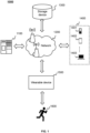
- FIG. 1 is a schematic diagram of a system for monitoring a leg circumference according to some embodiments of the present disclosure.
- a system 1000 for monitoring a leg circumference may include a processing device 1100, a network 1200, a storage device 1300, one or more terminal devices 1400, and a wearable device 1500.
- Components of the system 1000 may be connected in a variety of ways.
- the wearable device 1500 may be connected to the storage device 1300 and/or the processing device 1100 via the network 1200, and the wearable device 1500 may be connected to the storage device 1300 and/or the processing device 1100 directly.
- the storage device 1300 may be directly connected to the processing device 1100 or connected to the processing device 1100 via the network 1200.
- the one or more terminal devices 1400 may be connected to the storage device 1300 and/or the processing device 1100 via the network 1200, and the one or more terminal devices 1400 may be connected to the storage device 1300 and/or the processing device 1100 directly.
- the system 1000 may measure a circumferential dimension of a leg of a user and determine the circumference information of the leg of the user through one or more devices disclosed in the present disclosure.
- a sensor assembly of the wearable device 1500 measures the circumferential dimension of the leg of the user.
- the processing device 1100 may process the circumferential dimension of the leg of the user to determine the circumference information of the leg of the user.
- the processing device 1100 may process data and/or information obtained from the wearable device 1500, the storage device 1300, the one or more terminal devices 1400, and/or other components of the system 1000.
- the processing device 1100 may obtain circumferential dimensions of the leg (e.g., a thigh, a calf, etc.) of the user 1600 from any one of the wearable device 1500, the storage device 1300, the one or more terminal devices 1400, or a combination thereof and process the circumferential dimension to generate the circumference information of the leg of the user.
- the processing device 1100 may obtain a pre-stored computer instruction from the storage device 1300 and execute the computer instruction to implement the system 100.
- the processing device 1100 may be a single server or a group of servers. The group of servers may be centralized or distributed. In some embodiments, the processing device 1100 may be local or remote. For example, the processing device 1100 may access information and/or data from the wearable device 1500, the storage device 1300, and/or the one or more terminal devices 1400 via the network 1200. As another example, the processing device 1100 may be directly connected to the wearable device 1500, the storage device 1300, and/or the one or more terminal devices 1400 to access the information and/or data. In some embodiments, the processing device 1100 may be implemented on a cloud platform. For example, the cloud platform may include a private cloud, a public cloud, a hybrid cloud, a community cloud, a distributed cloud, an inter-cloud cloud, a multi-cloud, and the like, or any combination thereof.
- the cloud platform may include a private cloud, a public cloud, a hybrid cloud, a community cloud, a distributed cloud, an inter-cloud cloud, a multi-cloud, and
- the network 1200 may connect various components of the system 1000 and/or connect the system 1000 to an external resource portion.
- the network 1200 may enable communication between the components of the system 1000 and communication between the system 1000 and the external resource portion, to facilitate the exchange of data and/or information.
- the processing device 1100 may obtain the dimensional information (e.g., the circumferential dimension) from the wearable device 1500 and/or the storage device 1300 via the network 1200.
- the processing device 1100 may obtain a user operation instruction from the one or more terminal devices 1400 via the network 1200, and exemplary operation instructions may include, but are not limited to, setting user information (e.g., gender, age, height, weight, history of disease, etc.), starting to measure leg circumference, etc.
- the network 1200 may be any form of wired or wireless network, or any combination thereof.
- the network 120 may include a cable network, a wired network, a fiber optic network, a telecommunication network, an intranet, the Internet, a local area network (LAN), a wide area network (WAN), a wireless local area network (WLAN), a metropolitan area network (MAN), a public switched telephone network (PSTN), a Bluetooth network, a ZigBee network, a near-field communication (NFC) network, etc., or any combination thereof.
- the network 1200 may include at least one network access point, and at least one component of the system 100 may be connected to the network 1200 via the at least one access point to exchange data and/or information.
- data such as the circumferential dimension of the leg of the user, a circumferential dimension of the waist of the user, an electromyographic (EMG) signal of a muscle of the leg of the user, and the shape of the leg of the user may be communicated via the network 120.
- EMG electromyographic
- the storage device 1300 may store data, instructions, and/or any other information.
- the storage device 1300 may store data obtained from the wearable device 1500, the processing device 1100, and/or the one or more terminal devices 1400.
- the storage device 1300 may store the circumferential dimension acquired by the wearable device 1500.
- the storage device 1300 may store data and/or instructions used by the processing device 1100 to execute the exemplary methods described in the present disclosure.
- the storage device 1300 may include mass memory, removable memory, volatile read-write memory, read-only memory (ROM), or the like, or any combination thereof.
- Exemplary mass memory may include a disk, an optical disk, a solid-state disk, or the like.
- the storage device 1300 may be implemented on a cloud platform.
- the cloud platform may include a private cloud, a public cloud, a hybrid cloud, a community cloud, a distributed cloud, an on-premises cloud, a multi-tiered cloud, etc., or any combination thereof.
- the storage device 1300 may be connected to the network 1200 to communicate with at least one other component of the system 1000 (e.g., the wearable device 1500, the processing device 1100, the one or more terminal devices 1400). At least one component of the system 1000 may access data, instructions, or other information stored in the storage device 1300 via the network 1200.
- the storage device 1300 may be directly connected or in communication with one or more components (e.g., wearable device 1500, one or more terminal devices 1400) of the system 1000.
- the storage device 1300 may be part of the wearable device 1500 and/or the processing device 1100.
- the one or more terminal devices 1400 may receive, send, and/or display data.
- the received data may include data collected by the wearable device 15000, data stored by the storage device 1300, data generated by the processing device 1100, or the like.
- the data received and/or displayed by the one or more terminal devices 1400 may include the circumferential dimension collected by the wearable device 1500, the circumference information generated by the processing device 1100 by processing the circumferential dimension, or the like.
- the sent data may include user input data, instructions, etc.
- the one or more terminal devices 1400 may send an operation instruction inputted by the user to the wearable device 1500 via the network 1200 to control the wearable device 1500 to perform corresponding data collection.
- the one or more terminal devices 1400 may include a mobile device 1401, a tablet computer 1402, a laptop computer 1403, etc., or any combination thereof.
- the mobile device 1410 may include a cell phone, a personal digital assistant (PDA), a medical mobile terminal, etc., or any combination thereof.
- the one or more terminal devices 1400 may include an input device (e.g., a keyboard, a touch screen), an output device (e.g., a display, a speaker), or the like.
- the processing device 1100 may be part of the one or more terminal devices 1400.
- the wearable device 1500 is a device that performs data collection on the user 1600.
- the data includes data of the leg of the user 1600. Exemplary data may include circumferential dimensions, leg shape, EMG signals, or the like.
- the wearable device 1500 may have an independent power source and may send the collected data to other components (e.g., the processing device 1100, the storage device 1300, the one or more terminal devices 1400) in a wired or wirelessly (e.g., Bluetooth, WiFi, etc.) manner.
- one or more components on the system 1000 may be implemented on the wearable device 1500.
- the wearable device 1500 may include the processing device 1100, the storage device 1300, or the like. More descriptions of exemplary structures of the wearable device 150 may be found in FIG.2 A-FIG.10 and the related descriptions thereof.
- the user 1600 refers to a user of the wearable device 1500.
- the user 1600 may be a person concerned about the circumference of his or her legs, an exercise person, a tester of exercise equipment, a patient in need of rehab, or the like.
- the user 1600 may issue a query request.
- the user 1600 inquires about circumference information, circumference change information, stance information, training instruction advice, corrective advice, or the like, for his or her leg.
- the user may receive feedback from the wearable device 1500 or the one or more terminal devices 1400, such as receiving a query result (e.g., circumference information, circumference change information, posture information, etc.), a suggestion (e.g., a training instruction suggestion, a correction suggestion, etc.), or the like.
- a query result e.g., circumference information, circumference change information, posture information, etc.
- a suggestion e.g., a training instruction suggestion, a correction suggestion, etc.
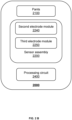
- FIG. 2 A and FIG. 2 B are block diagrams of a wearable device 2000 according to some embodiments of the present disclosure.
- the wearable device 2000 includes pants 2100 and a sensor assembly 2200 fixed on the pants 2100.
- the sensor assembly 2200 includes at least one circumferential strain sensor 2210, the at least one circumferential strain sensor 2210 extending along a circumferential direction of a pant leg of the pants 2100 to measure a circumferential dimension of a leg of a user.
- the pants 2100 may be of a variety of lengths, e.g., the pants 2100 may be shorts, seven-quarter pants, nine-quarter pants, pants, etc. Specifically, the length of the pants 2100 may be determined based on the position of the circumferential dimension of the leg that the user needs to monitor. For example, when the user only needs to monitor a circumferential dimension of a thigh, the pants 2100 may be shorts with the legs over the thighs, seven-quarter pants, or pants 2100 with a longer length. As another example, when the user needs to monitor a circumferential dimension of a calf, the pants 2100 may be nine-quarter pants or long pants.
- the pants 2100 may be long pants.
- the pants 2100 is a carrier for carrying a component such as the sensor assembly 2200.
- the pants 2100 may be replaced with other devices capable of being worn on the legs, such as leg straps (e.g., full leg straps, thigh straps, calf straps, etc.), leggings (e.g., full leggings, thighgings, calfgings, etc.), socks (e.g., calf socks, thigh socks, pantyhose, etc.), or the like.
- the sensor assembly 2200 is configured to collect data from the leg of the user.
- the sensor assembly 2200 may include at least one strain sensor (e.g., the circumferential strain sensor 2210 and a longitudinal strain sensor 2220 in the present disclosure, as shown in FIG. 2A ), and the sensor assembly 2200 may measure the circumferential dimension of the leg of the user via the at least one strain sensor (see FIGs. 3-8 and their related descriptions).
- a strain sensor is a type of sensor that measures the deformation of an object. Because the strain sensor is fixed to the pants 2100, when the user wears the pants 2100, the pants 2100 may deform, and the strain sensor may generate a strain based on the deformation of the pants 2100, thereby generating an electrical signal.
- the strain sensor may be flexible, not affecting the fit of the pants 2100 to the leg of the user when the pants 2100 deform.
- the strain sensor may be a capacitive strain sensor or a resistive strain sensor.
- each strain sensor e.g., each first strain sensor 2211/each second strain sensor 2212/each third strain sensor 2213
- each strain sensor may include a plurality of sensing modules. The plurality of sensing modules are sequentially arranged along an extension direction of the strain sensors, and each of the sensing modules is configured to experience a different magnitude of strain, thereby generating a different magnitude of electrical signal.
- the sensing modules please refer to the description below regarding the longitudinal strain sensor 2220.
- the sensor assembly 2200 may include an electrode module (e.g., a second electrode module 2240 in the present disclosure, as shown in FIG. 2B ), and the sensor assembly 2200 may measure the dimensions of the leg of the user via the electrode module (see FIG. 10 and its related description).
- an electrode module e.g., a second electrode module 2240 in the present disclosure, as shown in FIG. 2B
- the sensor assembly 2200 may measure the dimensions of the leg of the user via the electrode module (see FIG. 10 and its related description).
- the sensor assembly 2200 may be secured to an inner surface of the pants 2100. In other embodiments, the sensor assembly 2200 may be secured to an outer surface of the pants 2100 to prevent discomfort caused by the sensor assembly 2200 to the user. In yet other embodiments, the pants 2100 may have an interlayer, and the sensor assembly 2200 may be secured to the interlayer of the pants 2100, which may ensure the wearing comfort of the user while protecting the sensor assembly 2200. The sensor assembly 2200 may be secured to the pants through pasting, weaving, or the like.
- the sensor assembly 2200 may include a circumferential strain sensor 2210.
- the circumferential strain sensor 2210 extends along a circumferential direction of the pant leg of the pants 2100.
- the circumferential direction of the pant leg is indicated by the arrow A in FIG.3 - FIG.8 and FIG. 10 , and when the user wears the pants 2100, the circumferential direction of the pant leg is substantially the same as a circumferential direction of the leg of the user.
- the circumferential strain sensor 2210 may have a strip structure, and the strain sensor of the strip structure may be configured to be arranged circumferentially along (i.e., around) the leg of the user.
- the circumferential strain sensor 2210 may generate strain along the circumferential direction of the pant leg to measure the circumferential dimension of the leg of the user. It may be understood that during wearing, the circumferential strain sensor 2210 may continuously measure, measure at intervals (e.g., once every preset period), or measure according to an instruction, the circumferential dimension of the leg of the user to monitor the circumference of the leg of the user.
- a length of the circumferential strain sensor 2210 may be equal to a circumferential length of the pant leg at which the circumferential strain sensor 2210 is disposed. In some embodiments, the length of the circumferential strain sensor 2210 may be less than the circumferential length of the pant leg at which the circumferential strain sensor 2210 is disposed. For example, the length of the circumferential strain sensor 2210 may be 1/2, 1/3, 1/5, or the like, of the circumferential length of the pant leg at which the circumferential strain sensor 2210 is disposed.
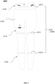
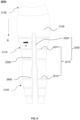
- FIG. 3 is a schematic diagram of an exemplary structure of a wearable device according to some embodiments of the present disclosure.
- at least one circumferential strain sensor 2210 of the wearable device 2000 may include a first strain sensor 2211 as shown in FIG. 3 .
- the first strain sensor 2211 may be configured to measure a circumferential dimension of a thigh of a user.
- the first strain sensor 2211 is disposed in a thigh region 2110 of a pant leg and extends in a circumferential direction (i.e., in the direction indicated by arrow A in FIG. 3 ) along the thigh region 2110 to measure the circumferential dimension of the thigh of the user.
- the first strain sensor 2211 may be a band that extends along the circumference of the thigh region 2110 of the pant leg.
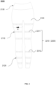
- the at least one circumferential strain sensor 2210 may include a plurality of first strain sensors 2211, the plurality of first strain sensors 2211 being spaced apart along a length direction of the pant leg.
- the plurality of first strain sensors 2211 may be spaced apart in the thigh region 2110 along the length direction of the pant leg, as shown in FIG. 4 .
- the plurality of first strain sensors 2211 may be spaced apart at equal intervals.
- a distance between two adjacent first strain sensors 2211 may be set according to a preset distance.
- the preset distance may be 8 cm, 10 cm, etc.
- the plurality of first strain sensors 2211 are configured such that circumferential dimensions at different positions of the thigh (e.g., at different positions in a length direction of the thigh) may be measured, thereby measuring the circumferential dimensions of the thigh more comprehensively.
- each of the plurality of first strain sensors 2211 may be arranged at a particular position on the thigh of the user. For example, a first strain sensor 2211 may be arranged at a position with a maximum circumferential dimension on the thigh and a first strain sensor 2211 may be arranged at a position with a minimum circumferential dimension on the thigh.
- the position on the thigh with the maximum circumferential dimension and the position on the thigh with the minimum circumferential dimension may be set according to a height or a leg length of the human body, or may be personalized according to a leg shape of the user.
- the plurality of first strain sensors 2211 may be arranged along the length direction of the thigh, from top to bottom, at 20% of a thigh length (i.e., a distance from the hip to the knee), 50% of the thigh length, and 80% of the thigh length, respectively.
- the at least one circumferential strain sensor 2210 of the wearable device 2000 may include a second strain sensor 2212, as illustrated in FIG. 3 .
- the second strain sensor 2212 may be configured to measure a circumferential dimension of a calf of the user.
- the second strain sensor 2212 is disposed in a calf region 2120 of the pant leg and extends in a circumferential direction (i.e., in the direction indicated by arrow A in FIG. 3 ) along the calf region 2120 to measure the circumferential dimension of the calf of the user.
- the second strain sensor 2212 may be a band that extends along the circumferential direction of the calf region 2120 of the pant leg.
- the at least one circumferential strain sensor 2210 may include a plurality of second strain sensors 2212, and the plurality of second strain sensors 2212 may be spaced apart along the length direction of the pant leg.
- the plurality of second strain sensors 2212 may be spaced apart in the calf region 2120 along the length direction of the pant leg, as shown in FIG. 4 .
- the plurality of second strain sensors 2212 may be spaced apart at equal intervals.
- a distance between two adjacent second strain sensors 2212 may be set according to a preset distance.
- the preset distance may be 8 cm, 10 cm, etc.
- the plurality of second strain sensors 2212 are configured such that the circumferential dimensions at different positions of the calf (e.g., at different positions in a length direction of the calf) may be measured, so as to more comprehensively measure the circumferential dimensions of the calf.
- each of the plurality of second strain sensors 2212 may be arranged at a particular position on the calf of the user. For example, a second strain sensor 2212 may be arranged at a position with a maximum circumferential dimension on the calf and a second strain sensor 2212 may be arranged at a position with a minimum circumferential dimension on the calf.
- the plurality of second strain sensors 2212 may be arranged along the length direction of the calf, from top to bottom, at 20% of a calf length (a distance from the knee to the ankle), 50% of the calf length, and 80% of the calf length, respectively.
- the at least one circumferential strain sensor 2210 further includes a third strain sensor 2213, the third strain sensor 2213 being disposed in a waist region 2130 of the pants 2100 and extending along a circumferential direction (i.e., in the direction indicated by the arrow C in FIG. 3 ) of the waist region 2130 to measure a circumferential dimension (i.e., a waist circumference) of the waist of the user.
- the third strain sensor 2213 may be a band-like structure that extends along the circumference direction (which corresponds to a circumference direction of the waist of the user after the user wears the wearable devices 2000) of the waist region 2130 of the pants 2100.
- the at least one circumferential strain sensor 2210 may include a plurality of third strain sensors 2213, the plurality of third strain sensors 2213 being spaced apart along the length direction of the pants 2100.
- the plurality of third strain sensors 2213 may be spaced apart at equal intervals.
- a distance between two adjacent third strain sensors 2213 may be set according to a preset distance.
- the preset distance may be 5 cm, 7 cm, etc.
- the plurality of third strain sensors 2213 may be configured such that circumferential dimensions at different positions of the waist (e.g., different positions in the length direction of the waist) may be measured, thereby measuring the circumferential dimensions of the waist more comprehensively.
- each of the plurality of third strain sensor 2213 may be arranged at a particular position on the waist of the user.
- a third strain sensor 2213 may be arranged at a position with a maximum circumferential dimension on the waist and a third strain sensor 2213 may be arranged at a position with a minimum circumferential dimension on the waist.
- a plurality of circumferential strain sensors 2210 located at different positions on the pants 2100 are provided such that the circumferential dimensions of the leg and the waist of the user can be conveniently measured, thereby facilitating the user to monitor his or her leg circumference and waist circumference.
- FIG. 5 is a schematic diagram of an exemplary structure of a wearable device according to yet some more embodiments of the present disclosure.
- FIG. 6 is a schematic diagram of an exemplary structure of a wearable device according to some further embodiments of the present disclosure.
- the wearable device 2000 further includes a longitudinal strain sensor 2220.
- FIG. 5 illustrates an exemplary arrangement of the longitudinal strain sensor 2220 when one first strain sensor 2211 and one second strain sensor 2212 are provided in the thigh region 2110 and the calf region 2120, respectively.
- FIG. 5 illustrates an exemplary arrangement of the longitudinal strain sensor 2220 when one first strain sensor 2211 and one second strain sensor 2212 are provided in the thigh region 2110 and the calf region 2120, respectively.
- FIG. 6 illustrates an exemplary arrangement of the longitudinal strain sensor 2220 when there are a plurality (three in the figure) of first strain sensors 2211 and a plurality (three in the figure) of second strain sensors 2212. More descriptions of the arrangements of the longitudinal strain sensor 2220 can be found in the following descriptions.
- the longitudinal strain sensor 2220 may be configured to measure a dimension in the length direction of the leg of the user to reflect the shape of the leg of the user. In some embodiments, the longitudinal strain sensor 2220 may extend along the length direction of the pant leg. It should be noted that FIGs. 3-8 may all be regarded as drawings in which the pants 2100 have been worn on the body of the user (merely by way of example, the length direction of the pant leg is substantially the same as the length direction of the leg of the user). Specifically, the length direction of the pants 2100 (or the length direction of the leg of the user) is shown in the direction indicated by arrow B in FIGs. 5-7 ).
- an extension direction of a portion of the longitudinal strain sensor 2220 may change when the user wears the pants 2100 because the shape of the leg of the user is not a regular cylindrical shape. However, when the user is not wearing the pants 2100, the longitudinal strain sensor 2220 extends in the length direction of the pant leg. At least a portion of the longitudinal strain sensor 2220 is located in the thigh region 2110 and at least another portion of the longitudinal strain sensor 2220 is located in the calf region 2120. In some embodiments, two ends of the longitudinal strain sensor 2220 are located in the thigh region 2110 and the calf region 2120, respectively. In other embodiments, the two ends of the longitudinal strain sensor 2220 are located in the waist region 2130 and the calf region 2120, respectively.
- one end of the longitudinal strain sensor 2220 is located in the thigh region 2110 above a knee region and the other end is located in the calf region 2120 below the knee region.
- the shape e.g., an angle between the thigh and the calf, a difference in the circumferential dimension of the thigh and the circumferential dimension of the calf
- the leg of the user affects the deformation of the pant leg in the length direction, which further affects the extension of the longitudinal strain sensor 2220 along the length direction of the pant leg.
- the shape of the leg such as a shape characteristic of the leg as a whole, a taper of the thigh, or the like, may be reflected. It may be understood that during wearing, the longitudinal strain sensor 2220 may measure continuously, measure at intervals (e.g., once every preset period), or measure according to an instruction, the dimension of the leg in the length direction of the leg of the user to monitor the shape of the leg of the user.
- the longitudinal sensor 2220 may monitor a posture of the leg of the user by monitoring the shape of the leg of the user. Due to different muscle exertion conditions in various postures of the leg, the shape of the leg of the user may differ. By comparing and analyzing a current shape of the leg of the user with the shape characteristics of the leg of the user in different postures, a current leg posture of the user may be determined. In some embodiments, the longitudinal sensor 2220 may monitor the movement of the leg of the user by detecting the shape of the leg of the user.
- one or more leg shapes of the user during the time period may be determined. If only one leg shape is detected during the time period, the user is probably in a roughly stationary state (e.g., sitting, standing, lying down, etc.). If a plurality of leg shapes are detected during the time period, a change (e.g., a periodic change) in the plurality of shapes of the leg may reflect a movement of the user.
- intervals e.g., once every preset period
- the shape of the leg of the user may undergo periodic changes of large-angle bending (i.e., the angle between the thigh and calf decreases substantially, e.g., the angle between the thigh and calf decreases to less than 45°) and straightening over a time period.
- large-angle bending i.e., the angle between the thigh and calf decreases substantially, e.g., the angle between the thigh and calf decreases to less than 45°
- At least one longitudinal strain sensor 2220 is located in a region of the pant leg that faces towards or is away from the other pant leg.
- the region of the pant leg that faces towards or is away from the other pant leg may be understood as a side of the pant leg.
- the region of the pant leg that faces towards the other pant leg may be understood as an inner side of the pant leg, and the region of the pant leg that is away from the other pant leg may be understood as an outer side of the pant leg.
- the longitudinal strain sensor 2220 may be configured such that the angle between the thigh and the calf of the user can be more accurately detected, the change in the shape of the leg of the user in the length direction may be more accurately sensed, and whether the user has a common leg shape problem (e.g., X-shaped leg, O-shaped leg, knee hyperextension, etc.) may be determined more accurately.
- a common leg shape problem e.g., X-shaped leg, O-shaped leg, knee hyperextension, etc.
- the at least one longitudinal strain sensor 2220 may include a plurality of longitudinal strain sensors 2220, and the plurality of longitudinal strain sensors 2220 may be spaced apart along the circumferential direction of the pant leg, as shown in FIG. 7 .
- the plurality of longitudinal strain sensors 2220 may be arranged on a front side, a back side, an outer side, an inner side, or the like, of the pants 2100.
- At least two longitudinal strain sensing sensors 2220 may be provided on the pant leg, with one of the at least two longitudinal strain sensors arranged on the outer side of the pant leg, and another one of the at least two longitudinal strain sensors 2220 arranged on the inner side of the pant leg.
- the at least one longitudinal strain sensor 2220 and the at least one circumferential strain sensor 2210 may be located on the same bearing layer of the pants 2100 for ease of processing.
- the at least one circumferential strain sensor 2210 (the first strain sensor 2211 and/or the second strain sensor 2212) may be arranged in an overlapping manner with the at least one longitudinal strain sensor 2220.
- the at least one longitudinal strain sensor 2220 may be arranged in an adjacent manner with the at least one circumferential strain sensor 2210. Adjacent arrangement may be understood as that there is no overlap between the at least one longitudinal strain sensor 2220 and the at least one circumferential strain sensor 2210 disposed on the same bearing layer in a thickness direction of the pants.
- the at least one longitudinal strain sensor 2220 and the at least one circumferential strain sensor 2210 located on the same bearing layer may be disposed adjacent to each other or spaced apart by a distance.
- a first gap 2500 is formed between two ends (e.g., two ends of a band-like structure) of the first strain sensor 2211 and a second gap 2600 is formed between two ends (e.g., two ends of a band-like structure) of the second strain sensor 2212.
- the first gap 2500 and the second gap 2600 may correspond to each other in the length direction of the pant leg. In other words, both the first gap 2500 and the second gap 2600 are located in a same straight line extending along the length direction of the pant leg.
- the at least one longitudinal strain sensor 2220 passes through the first gap 2500 and the second gap 2600. As shown in FIG.
- the first gap 2500 and the second gap 2600 are both located on the inner side of the pant leg, and the longitudinal strain sensor 2220 passes through the first gap 2500 and the second gap 2600.
- the longitudinal strain sensor 2220 may pass through the first gap 2500 formed by each of the plurality of first strain sensors 2211, respectively, and through the second gap 2600 formed by each of the plurality of second strain sensors 2212, respectively.
- the distribution of the at least one circumferential strain sensor 2210 and the at least one longitudinal strain sensor 2220 on the pants 2100 may be more reasonable to avoid an overlapping portion from generating a large bulge that affects the comfort of the user. Furthermore, the at least one circumferential strain sensor 2210 and the at least one longitudinal strain sensor 2220 can work stably without interfering with each other.
- the first strain sensor 2211 may include a plurality of first sub-strain sensors 2211-1 spaced apart at intervals along the circumferential direction of the pant leg
- the at least one second strain sensor 2212 may include a plurality of second sub-strain sensors 2212-1 spaced apart at intervals along the circumferential direction of the pant leg.
- the plurality of first sub-strain sensors 2211-1 and the plurality of second sub-strain sensors 2212-1 may be arranged in a one-to-one correspondence.
- the longitudinal strain sensor 2220 passes through a gap between two adjacent first sub-strain sensors 2211-1 and a gap between two adjacent second sub-strain sensors 2212-1.
- the gap between any two adjacent first sub-strain sensors 2211-1 may be a third gap 2700
- the gap between any two adjacent second sub-strain sensors 2212-1 may be a fourth gap 2800.
- the plurality of third gaps 2700 and the plurality of fourth gaps 2800 are arranged in a one-to-one correspondence.
- One third gap 2700 and one fourth gap 2800 arranged in the same straight line extending along the length direction of the pant leg are regarded as being correspondingly arranged. Any of the plurality of longitudinal strain sensors 2220 passes through the correspondingly arranged third gap 2700 and fourth gap 2800. As shown in FIG.
- the plurality of first sub-strain sensors 2211-1 may be spaced apart along the circumferential direction (around the thigh) of the pant leg.
- the plurality of second sub-strain sensors 2212-1 may be spaced along the circumferential direction (around the calf) of the pant leg.
- the counts of the first sub-strain sensors 2211-1 and the second sub-strain sensors 2212-1 are both two.
- the two first sub-strain sensors 2211-1 may be located on the front side and the back side of the pant leg (e.g., the thigh region 2110), respectively (the first sub-strain sensor 2211-1 on the back side is not shown in FIG.
- the counts of the third gaps 2700 and the fourth gaps 2800 are both two.
- the two third gaps 2700 may be located on the inner side and the outer side of the pant leg, respectively.
- the two fourth gaps 2800 may be located on the inner side and the outer side of the pant leg, respectively, correspondingly arranged with respect to the third gaps 2700.
- the count, length, and relative position of the first sub-strain sensors 2211-1 relative to each other along the circumferential direction of the thigh region 2110 of the pant leg may be determined based on the circumferential dimension of the thigh and the count of the longitudinal strain sensors 2220.
- the count, length, and relative position of the second sub-strain sensor 2212-1 along the circumference direction of the calf region 2120 of the pant leg may be determined based on the circumferential dimension of the calf and the count of the longitudinal strain sensors 2220.
- the relative position of the first sub-strain sensors 2211-1 along the circumferential direction of the thigh region 2110 of the pant leg determines the position of the third gaps 2700
- the relative position of the second sub-strain sensors 2212-1 along the circumferential direction of the calf region 2120 determines the position of the fourth gaps 2800.
- the relative position of the first sub-strain sensors 2211-1 along the circumferential direction of the thigh region 2110 of the pant leg and the relative position of the second sub-strain sensor 2212-1 along the circumferential direction of the calf region 2120 of the pant leg are configured such that the plurality of third gaps 2700 and the plurality of fourth gaps 2800 are arranged in a one-to-one correspondence.
- the longitudinal strain sensors 2220, the first strain sensors 2211, and the second strain sensors 2212 may be reasonable arranged such that the circumferential dimension, shape, and/or length of the leg of the user are measured accurately.
- gaps e.g., the first gap 2500, the second gap 2600, the third gap 2700, and the fourth gap 2800
- the at least one longitudinal strain sensor 2220 and the at least one circumferential strain sensor 2210 may not interfere with each other while ensuring the reasonable arrangement of the at least one longitudinal strain sensor 2220 and the at least one circumferential strain sensor 2210, and wearing discomfort caused by the overlapping of the at least one longitudinal strain sensor 2220 and the at least one circumferential strain sensor 2210 is avoided.
- the pants 2100 includes at least two bearing layers stacked in a thickness direction of the pants 2100. Specifically, a count of the bearing layers may be two, three, five, etc.
- the at least one circumferential strain sensor 2210 and the at least one longitudinal strain sensor 2220 are disposed on different bearing layers of the at least two bearing layers. In some embodiments, there may be an overlap between a projection of the circumferential strain sensor 2210 and a projection of the longitudinal strain sensor 2220 located on different bearing layers in space (along the thickness direction of the pants 2100).
- each of the at least one first strain sensor 2211 and the at least one second strain sensor 2212 may be a complete ring (without a gap), and the longitudinal strain sensor 2220 may extend directly from above the first strain sensor 2211 to below the second strain sensor 2212.
- the projections of the circumferential strain sensor 2210 and the longitudinal strain sensor 2220 located on different bearing layers in space (along the thickness direction of the pants 2100) may not overlap.
- the circumferential strain sensor 2210 and the longitudinal strain sensor 2220 do not come into direct contact with each other, thereby ensuring stable operation of the circumferential strain sensor and the longitudinal strain sensor.
- the configuration manner (e.g., the count and the position) of the strain sensors (e.g., the at least one circumferential strain sensor 2210 and the at least one longitudinal strain sensor 2220) on the left and right pant legs of the pants 2100 may be different, and the specific configuration manner of the strain sensors on the left and right pant legs may be designed according to usage needs of different users. For example, for a user needing single-leg rehab, the strain sensor may be set only on the pant leg corresponding to the leg to be rehabbed.
- FIG. 8 is a schematic diagram of an exemplary structure of a wearable device according to some other embodiments of the present disclosure.
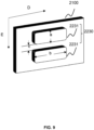
- FIG. 9 is a schematic diagram of an exemplary structure of a first electrode module according to some embodiments of the present disclosure.
- the wearable device 2000 may further include a first electrode module 2230.
- the first electrode module 2230 is configured to collect an electromyographic (EMG) signal of a muscle of a leg of a user.
- EMG electromyographic
- the first electrode module 2230 is configured to collect an EMG signal from a muscle of the leg of the user such that the exercise process (e.g., a process of working out, running, walking, etc.) of the user may be monitored based on the EMG signal, and the user may further be provided with exercise feedback.
- the EMG signal is a type of bioelectrical signal generated along with muscle contraction action. Based on an analysis result of the EMG signal, an activity and a function of the muscle may be reflected.
- the first electrode module 2230 may also be configured to detect a body composition of the leg of the user. For example, the first electrode module 2230 may detect an amount of fat, an amount of bone mass, or the like, in the leg of the user. The first electrode module 2230 can release an electrical signal of one or more frequencies into the human body and then collect the electrical signal. Since electrical signals of different frequencies propagate differently through various types of tissues in the human body, the impedance information may vary accordingly. By analyzing impedance information at different frequencies, the body composition can be interpreted.
- the first electrode module 2230 may be integrated in the pants 2100.
- the first electrode module 2230 may include two first electrodes.
- the two first electrodes 2231 of the first electrode module 2230 are in contact with the skin of the user to collect EMG signals on a skin surface.
- the two first electrodes 2231 are spaced apart along a muscle fiber direction (the direction indicated by the arrow E in FIG. 9 ) of a same muscle of the leg of the user.
- Arrow D in FIG. 9 illustrates an extension direction of the electrodes.
- the two first electrodes 2231 may be configured to collect EMG signals of the same muscle of the user.
- a differential operation may be performed on the EMG signals collected by different electrodes on the same muscle to reflect a force exertion of the muscle.
- the same muscle refers to a single muscle or the same muscle group (e.g., the quadriceps muscle group that includes the rectus femoris, lateral femoris, medial femoris, and intermediate femoris).
- the quadriceps muscle group that includes the rectus femoris, lateral femoris, medial femoris, and intermediate femoris.
- the at least two first electrodes 2231 are spaced apart along the muscle fiber direction of the muscle and extend in an extension direction perpendicular to the muscle fiber direction, respectively. Different locations in the muscle fiber direction have different electrical potentials, wherein a location of the muscle fiber where one of the at least two first electrodes 2231 is located has a first electrical potential, and a location of the muscle fiber where another one of the at least two first electrodes 2231 is located has a second potential. There is a potential difference between the first potential and the second potential, and the potential difference may reflect the force exertion of the muscle.
- the signal acquisition accuracy and/or efficiency of the electrodes may be improved by designing dimensions of the first electrodes 2231, a spacing between adjacent first electrodes 2231, or the like, to achieve more accurate and efficient signal acquisition.
- a width of the first electrode 2231 in the muscle fiber direction is denoted as a
- a length of the first electrode 2231 in the extension direction is denoted as b
- a spacing i.e., a distance between two adjacent sides of two adjacent first electrodes 2231
- the length b of the first electrode 2231 may be determined based on a size (or referred to as a muscle width) of the muscle in the extension direction (the direction indicated by arrow D in FIG. 8 ) of the electrode.
- the length b may have a relatively large value to minimize noise caused by a relative displacement between the electrode and the muscle, or to minimize an effect on a strength of the collected EMG signal when the electrode is deviated from a position of the muscle.
- the length b may be greater than or equal to the muscle width, greater than or equal to 30%, 50%, 60%, 80%, or the like of the muscle width.
- the two first electrodes may span two or more muscle groups (e.g., a target muscle group and a non-target muscle group), causing the collected EMG signals to interfere with each other, and further making it impossible to accurately detect the EMG signals of a target muscle.
- the length b may not be too large.
- the length b may be greater than or equal to 30% of a width of the target muscle and less than or equal to a sum of the width of the target muscle and a spacing between the target muscle and a non-target muscle.
- length b may be greater than or equal to 50% of the width of the target muscle and less than or equal to the width of the target muscle.
- the length b of the electrode corresponding to a single target muscle may be determined based on test data for the muscle. Taking the rectus femoris muscle as an example, a range of the length b of the electrode corresponding to the rectus femoris muscle may be determined based on the test data of the muscle. For example, the length b corresponding to the rectus femoris muscle may be in a range of 1 mm-120 mm. As another example, the length b corresponding to the rectus femoris muscle may be in a range of 10 mm-100 mm.
- the length b corresponding to the rectus femoris muscle may be in a range of 20 mm-80 mm.
- a scaling factor for a single target muscle may be determined based on a relative relationship (e.g., a size relationship) of the single target muscle to other target muscles, thereby determining the length b of the electrode corresponding to each muscle. For different target muscles, different scaling factors may be determined.
- the dimension of the biceps femoris muscle is similar to the rectus femoris muscle, and a scaling factor for the biceps femoris may be in a range of 0.8-1 (e.g., 0.9).
- the length b of the electrode corresponding to the biceps femoris muscle may be in a range of 0.9 mm-108 mm.
- the length b of the electrode corresponding to the biceps femoris muscle may be in a range of 9 mm-90 mm.
- the length b of the electrode corresponding to the biceps femoris muscle may be in a range of 18 mm-72 mm.
- the scaling factor for the tensor fasciae lata may be in a range of 0.5-0.8.
- the scaling factor for the tibialis anterior muscle may be in a range of 0.3-0.7.
- the scaling factor for the gastrocnemius muscle may be in a range of 0.4-0.8.
- the strength of the EMG signal collected by the electrodes may be positively correlated with the spacing c between two adjacent first electrodes 2231.
- the spacing c may not be too small so as not to affect the strength of the EMG signal.
- the spacing c of the two adjacent first electrodes 2231 may be set within a preset range.
- the spacing c may be in a range of 1 mm-50 mm.
- the spacing c may be in a range of 5 mm-40 mm.
- the spacing c may be in a range of 10 mm-30 mm.
- the width a of a single electrode and/or the spacing c between adjacent electrodes may be set in a preset range.
- the end positions may be two ends (i.e., two ends forming the width a ) of a single electrode along the muscle fiber direction.
- the width a of the single electrode may be set within the preset range.
- the end positions may be two ends (i.e., two ends of the first electrode 2231 away from each other) of the electrode as a whole in the muscle fiber direction.
- the width 2a+c of two adjacent first electrodes 2231 as a whole needs to be set within the preset range.
- the preset range may be related to a target frequency (e.g., 0-500 Hz, 10 Hz -300 Hz, 30 Hz -200 Hz, 60 Hz -140 Hz, etc.) at which phase cancellation needs to be avoided.
- the width a of a single first electrode 2231 may be less than a half-wavelength of the target frequency of the EMG signal.
- the width 2a+c of two adjacent first electrodes 2231 as a whole may be less than a full wavelength of the target frequency of the EMG signal.
- the length b of the first electrode 2231 is relatively large and the width a is relatively small.
- the length b of the first electrode 2231 in the muscle fiber direction is greater than the width a of the first electrode 2231 in the extension direction (i.e., b/a ⁇ 1).
- the performance or comfort of the wearable device 2000 may be improved by designing a material, a structure, or the like of the at least two first electrodes 2231.
- the at least two first electrodes 2231 may be waterproof, which may prevent short-circuiting between electrodes.
- the at least two first electrodes 2231 may be made of an elastic material so that the wearable device 2000 may be put on and taken off more easily, improving the comfort of the wearable device 2000.
- an elasticity of the elastic material of the at least two first electrodes 2231 may be in a range of 0% to 200%.
- the at least two first electrodes 2231 may be resistant to withstand multiple washing machine loads, repeated donning and doffing, skin rubbing, or the like without affecting other properties.
- the at least two first electrodes 2231 may be corrosion resistant (e.g., sweat corrosion).
- the at least two first electrodes 2231 may have good electrical conductivity.
- the at least two first electrodes 2231 may have a conductivity of greater than 10K ⁇ /cm, and a change in conductivity of the at least two first electrodes 2231 under the influence of, for example, deformation of the electrode may be less than 10K ⁇ or less than 20% of the original conductivity.
- the at least two first electrodes 2231 may be permeable.
- the at least two first electrodes 2231 may be made of a breathable material (e.g., conductive fabric).
- the at least two first electrodes 2231 may have a gas permeable structure (e.g., perforations, intermediate layer gas channels, etc.).
- the at least two first electrodes 2231 may have a degree of softness that ensures comfort of the wearable device 2000.
- the at least two first electrodes 2231 may protrude towards the skin surface with respect to a substrate structure (or a wearing body), so that a localized pressurization effect may be achieved to promote the fit of the at least two first electrodes 2231 to the skin surface.
- a protrusion height of the at least two first electrodes 2231 may be in a range of 0-10 mm.
- a filler may be provided between the at least two first electrodes 2231 and the substrate structure to realize the projection of the at least two first electrodes 2231.
- the filler is a substance (e.g., a sponge, etc.) having a predetermined resilience, softness, water retention capacity, or the like.
- the predetermined resilience and softness ensure that the wearable device 2000 is comfortable when worn.
- the predetermined water retention capacity can reduce the accumulation of excessive water on the skin surface and at the same time store part of the water to guarantee the at least two first electrodes 2231 and the skin to have a good contact for a long time.
- the at least one circumferential strain sensor 2210 is arranged between two first electrodes 2231 of the first electrode module 2230 to ensure that the at least one circumferential strain sensor 2210 and the first electrode module 2230 are arranged compactly, thereby avoiding overlapping adversely affects the extensibility of the at least one circumferential strain sensor 2210, while ensuring stable operation of the at least one circumferential strain sensor 2210 and the first electrode module 2230.
- first electrode modules 2230 there may be a plurality of first electrode modules 2230, and the plurality of first electrode modules 2230 may be arranged in regions such as the thigh region 2110 and the calf region 2120 of the pant leg.
- the plurality of first electrode modules 2230 disposed in the thigh region 2110 may be spaced apart along the circumferential direction of the pant leg, and the first strain sensors 2211 may be arranged between two first electrodes 2231 of each first electrode module 2230.
- FIG. 8 illustrates a case in which the first electrode module 2230 is disposed in the thigh region 2110 and on the front side of the pant leg.
- a plurality of first electrode modules 2230 disposed in the calf region 2120 may be spaced apart along the circumferential direction of the pant leg, and the first strain sensors 2211 may be disposed in the calf region 2120 between two first electrodes 2231 of each first electrode module 2230. In some other embodiments, the at least one circumferential strain sensors 2210 may also be disposed above or below the first electrode module 2230.
- FIG. 10 is a schematic diagram of an exemplary structure of a wearable device according to some embodiments of the present disclosure.
- the sensor assembly 2200 includes a second electrode module 2240.
- the second electrode module 2240 includes at least one second electrode 2241.
- the second electrode module 2240 is arranged on the pants 2100, the at least one second electrode 2241 extends along a circumferential direction of a pant leg of the pants, and the second electrode module 2240 may be configured to measure a circumferential dimension of a leg of the user.
- the pant leg When the user wears the pants 2100, the pant leg generates a circumferential deformation, causing the at least one second electrode 2241 to simultaneously deform along the circumferential direction of the pant leg, resulting in a change (e.g., increase) in the resistance of the at least one second electrode 2241.
- a change e.g., increase
- an amount of circumferential deformation of the second electrode 2241 may be determined, and the circumferential dimension of the leg of the user may be determined.
- an area occupied by the sensor assembly 2200 on the pants 2100 may be reduced, thereby effectively avoiding wearing discomfort.
- the second electrode module 2240 may measure continuously, measure at intervals (e.g., once every preset period), or measure according to an instruction, the circumferential dimension of the leg of the user to monitor the circumference of the leg of the user.
- the second electrode module 2240 includes at least two second electrodes 2241, and the second electrodes 2241 may be in contact with the skin of the user.
- the at least two second electrodes 2241 are spaced apart along a muscle fiber direction of the same muscle of the leg of the user.
- the second electrode module 2240 may measure the dimensions of the leg of the user and collect an EMG signal of a muscle of the leg of the user.
- the principle of the second electrode module 2240 collecting the EMG signal is similar to the principle of the first electrode module collecting the EMG signal, as described above regarding the first electrode module 2230.
- the at least two second electrodes 2241 is configured to fit the skin of the user such that the second electrode module 2240 monitors the activity and function of the leg of the muscle of the user by collecting the EMG signal of the muscle of the leg of the user while detecting the circumference of the leg by measuring the circumferential dimensions of the leg of the user.
- the plurality of second electrode modules 2240 located in the thigh region 2110 and the plurality of second electrode modules 2240 located in the calf region 2120 may be spaced apart along the circumferential direction of the pant leg.
- the plurality of second electrode modules 2240 may also be spaced apart along a length direction of the pant leg.
- the plurality of second electrode modules 2240 may also be arranged in the waist region 2130 of the pants to measure the waist circumference of the user.
- the second electrode 2241 may be made of a material that is conductive but also possesses an impedance characteristic.
- the second electrode 2241 may be made of a material with a conductivity of less than 500 ⁇ /cm.
- the second electrode 2241 may be made of conductive silicon (with a resistance at the kilo-ohm level).
- the second electrode 2241 is made of a specific material such that the resistance of the second electrode 2241 is increased, and the amount of change in the resistance of the second electrode 2241 affected by the amount of the deformation of the second electrode 2241 is subsequently increased, thereby enhancing the accuracy of the second electrode 2241 in measuring the circumferential dimension of the leg of the user.
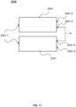
- FIG. 11 is a schematic diagram of an exemplary structure of a second electrode module 2240 according to some embodiments of the present disclosure.
- the second electrode module 2240 includes at least two second electrodes ( FIG. 11 shows two second electrodes).
- Each second electrode 2241 is provided with a first signal lead-out end 2241-1, a second signal lead-out end 2241-2, and a third signal lead-out end 2241-3.
- the first signal lead-out end 2241-1 and the second signal lead-out end 2241-2 are configured to lead out a signal of a circumferential dimension of a leg of a user, and the third signal lead-out end 2241-3 is configured to lead out a potential signal.
- the first signal lead-in end 2241-1 and the second signal lead-out end 2241-2 are located at two ends of an extension direction of the second electrode 2241, respectively, to facilitate measuring a resistance of the second electrode 2241 through the first signal lead-in end 2241-1 and the second signal lead-out end 2241-2.
- the third signal lead-out end 2241-3 of each second electrode 2241 may lead out the potential signal collected by the second electrode 2241. Based on the potential signals led out by the third signal lead-out ends of at least two second electrodes 2241, a potential difference may be determined, thereby enabling the second electrode module 2240 to collect an EMG signal.
- the first signal lead-in end 2241-1, the second signal lead-in end 2241-2, and the third signal lead-in end 2241-3 are configured such that the second electrode module 2240 may measure the circumferential dimension of the leg of the user and collect the EMG signal of a muscle of the leg of the user without interfering with each other, and the signal of the circumferential dimension of the leg and the EMG signal can be led out without interfering with each other.
- the second electrode 2241 is a unidirectional deformable electrode adapted to a predetermined direction.
- a unidirectional deformation electrode that is adapted to a predetermined direction is an electrode that deforms only along a predetermined direction. Thus, even if the unidirectional deformation electrode is subjected to forces from more than one direction, it deforms only along the predetermined direction, with almost no deformation occurring in other directions.
- an amount of deformation (e.g., an extended length, f1) of the unidirectional deformation electrode in the predetermined direction is much larger than an amount of deformation (e.g., an extended length, f2) of the unidirectional deformation electrode in the other directions (i.e., directions other than the predetermined direction).
- f1 is more than 10 times of f2.
- the second electrode 2241 may be configured as a unidirectional deformation electrode through a structural design or a weaving form.
- the second electrode 2241 may include a plurality of electrode sheets arranged along a length direction (perpendicular to a circumferential direction of the pant leg) of the pant leg.
- An elastic member e.g. an elastic cord
- the electrode sheets undergo strain, resulting in a change in the resistance of each electrode sheet, which in turn changes the resistance of the second electrode 2241.
- the second electrode 2241 is a unidirectional strain-sensitive electrode adapted to a predetermined direction.
- a unidirectional strain-sensitive electrode adapted to a predetermined direction is an electrode that changes electrical resistance only in response to a deformation of the unidirectional strain-sensitive electrode along the predetermined direction.
- the unidirectional strain-sensitive electrode deforms in response to forces applied from various directions, but the resistance of the unidirectional strain-sensitive electrode changes only in response to a deformation occurring in the predetermined direction and does not change (significantly) in response to deformations in other directions.
- a change in the resistance of the unidirectional strain-sensitive electrode in response to an amount of deformation in the predetermined direction is much larger than a change in the resistance of the unidirectional strain-sensitive electrode in response to the same amount of deformation in the other directions (directions other than the predetermined direction), e2.
- e1 is more than 10 times of e2.
- the predetermined direction is the circumferential direction of the pant leg.
- the second electrode 2241 is a unidirectional deformation electrode or a unidirectional strain-sensitive electrode adapted to a circumferential deformation of the pant leg.
- the second electrode 2241 deforms only along the circumferential direction of the pant leg.
- an amount of deformation e.g., an extended length f3
- an amount of deformation e.g., an extended length f4
- f3 is more than 10 times of f4.
- the second electrode 2241 when the user puts on the pants 2100, the second electrode 2241, while deforming in various directions, only responds to the deformation along the circumferential direction of the pant leg to generate a change in the resistance, i.e., the second electrode 2241 is sensitive to a force in only a single direction (i.e., the circumferential direction of the pant leg), and generates almost no change in resistance in response to deformations in directions other than the circumferential direction of the pant leg.
- a change e3 in the resistance of the second electrode 2241 generated in response to an amount of deformation of the pant leg along the circumferential direction thereof is much larger than a change e4 in the resistance of the second electrode 2241 generated in response to the same amount of deformation of the pant leg in other directions (directions other than the circumferential direction).
- e3 is more than 10 times of e4.
- the sensor assembly 2200 further includes a third electrode module 2250, the third electrode module 2250 including at least one third electrode 2251.
- the predetermined direction is a length direction of the pant leg.
- the third electrode 2251 is a unidirectional deformation electrode or a unidirectional strain-sensitive electrode adapted to a deformation of the pant leg along the length direction of the pant leg. When the user wears the pants 2100, the third electrode 2251 deforms only along the length direction of the pant leg.
- an amount of deformation (e.g., an extended length f5) of the third electrode 2251 along the length direction of the pant leg is much larger than an amount of deformation (e.g., an extended length f6) of the third electrode 2251 in other directions (directions other than the length direction).
- f5 is more than 10 times of f6.
- the third electrode 2251 when the user wears the pants 2100, the third electrode 2251, while deforming in various directions, only generates a change in the resistance in response to the deformation of the pant leg in the length direction of the pant leg, i.e., the third electrode 2251 is only sensitive to a force in a single direction, and generates almost no change in resistance in response deformations in directions other than the length direction of the pant leg.
- a change e5 in the resistance of the third electrode 2251 generated in response to the amount of deformation of the pant leg in the length direction is much larger than a change e6 in the resistance of the third electrode 2251 generated in response to the same amount of deformation of the pant leg in other directions (directions other than the length direction).
- e5 is more than 10 times of e6.
- the third electrode module 2250 is configured such that the amount of deformation of the pant leg along its length direction can be accurately measured, thereby providing a reference for determining the shape of the leg of the user.
- the third electrode 2251 may be configured as a unidirectional deformation electrode or a unidirectional strain-sensitive electrode adapted to the deformation of the pant leg along the length direction of the pant leg in a manner similar to the way in which the second electrode 2241 is configured as a unidirectional deformation electrode or a unidirectional strain-sensitive electrode adapted to the deformation of the pant leg along the circumferential direction of the pant leg.
- the sensor assembly 2200 may include a fourth electrode module.
- the fourth electrode module may include at least two fourth electrodes (not shown in the figures) configured as unidirectional deformation electrodes or unidirectional strain-sensitive electrodes for deformations of different directions of the pant leg.
- one of the at least two fourth electrodes may be a unidirectional strain-sensitive electrode adapted to the deformation of the pant leg in the length direction of the pant leg
- another one of the at least two fourth electrodes may be a unidirectional strain-sensitive electrode adapted to the deformation of the pant leg along the circumferential direction of the pant leg. In such cases, deformations in two directions of the pant leg can be accurately measured through a single electrode module.
- regions of the pant leg where different strain sensors are located may have different elasticities.
- an elasticity coefficient of the calf region 2120 of the pant leg in which the second strain sensor 2212 is located may be relatively large to prevent varicose veins in the calf region.
- the elasticity coefficient of the calf region 2120 of the pant leg in which the second strain sensor 2212 is located is greater than the elasticity coefficient of the thigh region 2110 of the pant leg in which the first strain sensor 2211 is located.
- an elasticity coefficient of the waist region 2130 of the pants in which the third strain sensor 2213 is located may be relatively small.
- the elasticity coefficient of the waist region 2130 in which the third strain sensor 2213 is located is smaller than the coefficient of elasticity of the thigh region 2110 of the pant leg where the first strain sensor 2211 is located.
- the elasticity coefficient of the corresponding region on the pants may be changed by changing the way the pants are cut and the material configuration of the pants (e.g., the tailoring and material configuration of the thigh region 2110 and the calf region 2120), and/or by modifying a structure or a material of the strain sensor.
- a strain sensor that is less prone to deformation e.g., has a relatively large elasticity coefficient
- a strain sensor that is more prone to deformation e.g., has a relatively small elasticity coefficient
- a force exerted by the pants 2100 on the calf region 2120 is greater than a force exerted by the pants 2100 on the thigh region 2110.
- the wearable device 2000 may further include a processing circuit 2400.
- the processing circuit 2400 may be integrated in the pants 2100. In some embodiments, the processing circuit 2400 may be integrated in the waist region 2130 of the pants 2100. In some embodiments, the processing circuit 2400 may be the processing device 1100 in FIG. 1 . In other embodiments, the processing circuit 2400 may be part of the processing device 1100 in FIG. 1 .
- the processing circuit 2400 may be configured to process or send the circumferential dimension of the leg of the user. For example, the processing circuit 2400 may transmit the circumferential dimension of the leg of the user to the storage device 1300 or the one or more terminal devices 1400 via the network 1200.
- the processing circuit 2400 may directly process the circumferential dimension to generate feedback information, which may be presented to the user.
- the feedback information may include circumference information of the leg of the user, circumference change information, a model of the leg of the user, training instruction recommendations, postural information, corrective recommendations, or the like.
- the present disclosure also provides a wearable device that includes the pants 2100 and the sensor assembly 2200 as described in any of the aforementioned embodiments, and a processor 3000.
- the processor 3000 is configured to process data (e.g., circumferential dimensions, the shape of the leg, the EMG signal, etc.) measured by the sensor assembly (e.g., the circumferential strain sensor 2210, the longitudinal strain sensor 2220, the first electrode module 2230, the second electrode module 2240, or the third electrode module 2250).
- the processor 3000 may control the wearable device 2000 to perform a predetermined operation.
- the processor 3000 may control the sensor assembly 2200 to measure a circumferential dimension of the leg of the user.
- the processor 3000 may control the sensor assembly 2200 to measure the circumferential dimension of the leg of the user at regular intervals.
- the processor 3000 may be the processing device 1100 described in FIG. 1 .
- processor 3000 may include the processing circuit 2400 as described above.
- the processor 3000 may be integrated into the pants 2100 (e.g., the waist region 2130 of the pants 2100) or may be located in a cloud to access the data collected by the sensor assembly 2200 through remote communication with the sensor assembly 2200.
- FIG. 12 is a block diagram of a processor of a wearable device according to some embodiments of the present disclosure.
- the processor 3000 may include an acquisition module 3100, a circumference generation module 3200, a model generation module 3300, a training recommendation module 3400, and a posture determination module 3500.
- the above modules are intended to be illustrative, and are not meant to limit the functionality of the processor 3000.
- the processor 3000 may include only one or more of these modules, or the processor 3000 may include other modules.
- the processor 3000 may be configured to obtain a circumferential dimension of the leg of a user, and based on the circumferential dimension, generate circumference information of the leg of the user.
- the operation of obtaining the circumferential dimension of the leg of the user may be performed by the acquisition module 3100, and the operation of generating the circumference information of the leg of the user may be performed by the circumference generating module 3200.
- the acquisition module 3100 may acquire the circumferential dimension of the leg of the user from the sensor assembly 2200 (e.g., the circumferential strain sensor 2210 or the second electrode module 2240).
- the circumference information may reflect the circumference of the leg of the user, and the circumference information may include circumferential dimensions of a plurality of parts (e.g., a thigh, a calf, a knee, an ankle, etc.) of the leg of the user.
- the generated circumference information may be sent to the one or more terminal devices 1400.
- the circumference information may be stored in the storage device 1300.
- the circumference information includes information about a change in the circumference over a first preset time period.
- the circumference change information may include data such as a trend (e.g., a trend of increase or decrease) and an amount of change in the circumferential dimension of the leg of the user over the first preset time period.
- the first preset time period may be a day, a week, a month, a year, or the like. Alternatively, the first preset time period may be a period of time defined by the user.
- the processor 3000 may be configured to monitor the circumferential dimension of the leg of the user during the first preset time period and generate the circumference change information.
- the processor 3000 may control the sensor assembly 2200 to collect (e.g., once every interval of time) circumferential dimensions of the leg of the user multiple times during the first preset time period, and generate the circumference change information based on the plurality of circumferential dimensions collected multiple times.
- the processor 3000 may control the sensor assembly 2200 to collect circumferential dimensions of the thigh region 2110 of the leg of the user (e.g., via the first strain sensor 2211) every day for a month, and then based on the circumferential dimensions in the month, determine a trend of change, an amount of change, or the like in the circumference of the leg of the user.
- the processor 3000 may control the sensor assembly 2200 to collect circumferential dimensions of the thigh region 2110 of the leg of the user (e.g., via the first strain sensor 2211) every day for a month, and then based on the circumferential dimensions in the month, determine a trend of change, an amount of change, or the like in the circumference of the leg of the user
- the sensor assembly 2200 detects the shape of the leg of the user via the longitudinal strain sensor 2220.
- the processor 3000 may be configured to generate a model of the leg of the user based on the shape and the circumferential dimension of the leg of the user. This operation may be performed by the model generation module 3300. Exemplary models of the leg may include a two-dimensional (2D) image model, a three-dimensional (3D) image model, or the like.
- the model generation module 3300 sends the generated model of the leg of the user to the one or more terminal devices 1400.
- the generated model of the leg of the user may be stored in the storage device 1300.
- the processor 3000 may be configured to generate a first training guidance recommendation based on the circumference information of the leg of the users. This operation may be performed by the training recommendation module 3400.
- the first training guidance recommendation may be a training guidance recommendation for targeted training based on the circumference information of the leg of the user.
- the first training guidance recommendation may be a training guidance recommendation that targets training for one or more specific parts of the leg.
- the first training guidance recommendation may include a link to a training session, a training guidance video, etc.
- the first training guidance recommendation for targeted training of the thigh may be fed back to the user.
- a link to a training course or a training instruction video for targeted training of the thigh may also be sent to the user. In this way, based on specific data of the user, the user may be scientifically guided to train in a targeted manner to achieve better shaping or fitness results.
- the processor 3000 may further adjust the first training guidance recommendation based on the circumference change information. For example, after the user has been training for a period of time, if the circumference change information shows that the circumference change of the user's training part (e.g., a thigh) is not optimal, the processor 3000 may modify the first training guidance recommendation (e.g., replacing the link to a training session with a more intense workout).
- the processor 3000 may modify the first training guidance recommendation (e.g., replacing the link to a training session with a more intense workout).
- the wearable device 2000 further includes the first electrode module 2230 integrated into the pants 2100, and the processor 3000 may be configured to generate, based on the circumferential dimension of the leg of the user and an EMG signal, a second training guidance recommendation.
- the second training guidance recommendation may be a training guidance recommendation generated based on the EMG signal of the user during exercise.
- the EMG signal may reflect the activity and function of the muscle during the user's exercise, and based on the analysis of the EMG signal, the user may be provided with training guidance recommendations from the perspective of training intensity.
- Exemplary second training guidance recommendations may include at least one of a fatigue reminder, a recommendation for a running exercise amount, a recommendation for target muscle strength training, or the like.
- the processor 3000 may determine, based on the circumferential dimension of the leg of the user, a part of the leg of the user that needs targeted training, and determine a corresponding training session. Further, the processor 3000 may adjust, based on the EMG signal of the user during exercise, the training intensity of the training session.
- the training session may be related to the training intensity of a target muscle or a target muscle group.
- the processor 3000 may extract one or more characteristic values from the EMG signal that characterize the intensity of muscle training, and determine whether the characteristic values satisfy a predetermined condition (e.g., the characteristic values are greater than a certain threshold) to reflect whether the user's current exercise satisfies a desired training effect for the target muscle or the target muscle group.
- a predetermined condition e.g., the characteristic values are greater than a certain threshold
- the processor 3000 may generate a recommendation to remind the user to adjust his or her movement or exertion technique.
- Exemplary characteristic values characterizing the intensity of muscle training may include amplitudes of the EMG signal, an absolute value of the amplitudes, an average value of the amplitudes (or the absolute value), a maximum value of the amplitudes, a minimum value of the amplitudes, a median frequency, a peak frequency, a total value of force exertion, an EMG power, a foot touchdown time, an average frequency, or the like, during a target time interval.
- the processor 3000 may generate the second training guidance recommendation by adjusting the first training guidance recommendation based on the EMG signal. For example, the processor 3000 may adjust a count of repetitions of an action in the first training guidance recommendation to generate the second training instruction recommendation.
- the second training guidance recommendation may be generated based on the first training guidance recommendation and historical EMG signals of the user.
- the processor 3000 may generate the second training guidance recommendation by adjusting the first training guidance recommendation based on the first training guidance recommendation in conjunction with the EMG signal of the user collected from a previous training session.
- the generated first training guidance recommendation and the second training guidance recommendation may be sent to the one or more terminal devices 1400.
- the generated first training guidance recommendation and the second training guidance recommendation may be stored in the storage device 1300.
- the processor 3000 may be configured to determine posture information reflecting a posture of the leg of the user based on the shape and/or the circumferential dimension of the leg of the user. This operation may be performed by the posture determination module 3500.
- the posture information includes a current posture of the leg of the user and a duration for which the leg of the user is in the current posture. Since the exertion of leg muscles varies in different postures, the shape and the circumferential dimension of the leg of the user may be different. By comparing and analyzing a current shape and a current circumferential dimension of the leg of the user with shapes and circumferential dimensions of the leg of the user in different postures, the posture information reflecting the current posture of the leg of the user can be determined.
- the posture information may be information related to a posture of the user, and the posture may include one or more of a standing posture, a sitting posture, a walking posture, an exercising posture, a lying down posture, and a preset improper posture (e.g., stilted legs, cross-legged sitting, kneeling, etc.).
- a standing posture e.g., a standing posture, a sitting posture, a walking posture, an exercising posture, a lying down posture
- a preset improper posture e.g., stilted legs, cross-legged sitting, kneeling, etc.
- the duration for which the leg of the user is in the current posture is the total duration for which the leg of the user is in the current posture in a specific time period.
- the processor may determine the total duration for which the user is in the sit-to-stand posture in a day.
- the specific time period may be a time period such as a day, a week, or a period of time defined by the user. Determining the duration for which the leg of the user is in the current posture and feeding it back to the user may enable the user to understand the duration for which the user is in the current posture in a specific time period, and thus to understand his or her activities during the time period.
- the user may track how long he or she has been sitting throughout a day to assess whether he or she has been sitting for an excessively long time.
- the processor may generate a reminder message in response to the leg of the user being in the current posture for a period longer than a predetermined duration, and feedback the reminder message to the user. For example, when the current posture of the user is a sit-to-stand posture, the processor generates a reminder message when the user is in the sit-to-stand posture for longer than a predetermined duration (e.g., one hour), and feeds the reminder message to the user.
- a predetermined duration e.g., one hour
- the posture includes at least a preset improper posture.
- the preset improper posture may include a crossed-leg posture, sitting cross-legged in a kneeling position, or the like.
- the processor 3000 may be configured to: in response to determining that the current posture of the leg of the user is the preset improper posture, determine the duration for which the leg of the user is in the preset improper posture based on the shape of the leg of the user and/or the circumferential dimension of the leg of the user, and generate a corrective recommendation based on the duration for which the leg of the user is in the preset improper posture.
- the above operation may be performed by the posture determination module 3500.
- the corrective recommendation includes a reminder that the user has maintained the preset improper posture for too long, a warning about the hazards of the improper posture, and a corrective suggestion for the improper posture (e.g., advice on correct sitting posture). For example, if the duration for which of the leg of the user is in the crossed-leg posture exceeds a preset time, the processor 3000 may generate a corrective recommendation. In some embodiments, the generated corrective recommendation may be sent to the one or more terminal devices 1400. In some embodiments, the generated corrective recommendation may be stored in the storage device 1300.
- the posture includes at least a walking posture and a running posture.
- the processor 3000 may be configured to: in response to determining that the current posture of the leg of the user is the walking posture or the running posture, determine at least one of a step count, a step length, or a step frequency of the user based on the shape of the leg of the user and/or the circumferential dimension of the leg of the user.
- the shape and the circumferential dimension of the leg of the user may exhibit obvious periodic changes. Whether the user is in the walking posture or the running posture may be determined based on the changes.
- the step frequency of the user may be determined based on how often the shape and the circumferential dimension of the leg of the user show significant periodic changes, and the step length of the user may be determined based on a change in the shape of a specific part (e.g., a thigh and a calve) of the leg and a change in an angle between the thigh and the calf.
- a specific part e.g., a thigh and a calve
- the processor may generate a reminder or a recommendation based on at least one of the step counts, the step length, or the step frequency of the user. For example, the processor may generate a recommendation for the user to perform more walking exercises in response to determining that the step count of the user is less than a preset step count threshold (e.g., 2,000 steps) over a period of time (e.g., a day).
- a preset step count threshold e.g., 2,000 steps
- the posture includes at least a workout posture.
- the processor 3000 may be configured to: in response to determining that the current posture of the leg of the user is the workout posture, counting workout movements of the leg of the user based on the shape of the leg of the user and/or the circumferential dimension of the leg of the user. This operation may be performed by the posture determination module 3500.
- the posture determination module 3500 When the user is in the workout posture where the shape of the leg is constantly changing and the muscles constantly exert force, the circumferential dimension of the leg of the user changes constantly. Thus, based on measurements of the shape and the circumferential dimension of the leg of the user, whether the user is in the workout posture is determined.
- Counting the workout movements of the leg of the user may include determining the workout movements of the leg of the user and determining a count of repetitions of each workout movement. Based on the shape and the circumferential dimension of the leg of the user, the processor 3000 may determine the workout movements (e.g., jumping jacks, squats, etc.) being performed by the user, and when the movements are performed repeatedly mode, the processor 3000 may obtain the count of repetitions of each workout movement. Merely by way of example, the posture determination module 3500 may obtain the count of jumping jacks performed by the leg of the users. By counting the workout movements performed by the leg of the user, the user may have a clearer understanding of his or her workout. In some embodiments, a counting result of the workout movements of the leg of the user may be sent to the one or more terminal devices 1400. In some embodiments, the counting result of the workout movements of the leg of the user may be stored in the storage device 1300.
- the workout movements e.g., jumping jacks, squat
- the processor may generate a reminder or a recommendation based on the counting result of the workout movements of the leg of the user. For example, if the count of squats performed by the leg of the user is greater than a preset count, the processor may generate a reminder to alert the user to reduce the training intensity. In some embodiments, the processor may generate the reminder or the recommendation based on the counting result of workout movements of the leg of the user and an EMG signal. For example, after the user performs a training session, the processor determines the count of squats performed by the leg of the user during the training session.
- the processor may generate a recommendation for adjusting the count of squats (e.g., recommending that the count of squats be adjusted from 40 to 20).
- the numbers expressing quantities or properties configured to describe and claim certain embodiments of the present disclosure are to be understood as being modified in some instances by the term "about,” “approximate,” or “substantially.” For example, “about,” “approximate,” or “substantially” may indicate ⁇ 20% variation of the value it describes, unless otherwise stated. Accordingly, in some embodiments, the numerical parameter set forth in the written description and attached claims are approximations that may vary depending upon the desired properties sought to be obtained by a particular embodiment. In some embodiments, the numerical parameter should be construed in light of the number of reported significant digits and by applying ordinary rounding techniques. Notwithstanding that the numerical ranges and parameter setting forth the broad scope of some embodiments of the present disclosure are approximations, the numerical values set forth in the specific examples are reported as precisely as practicable.
Landscapes
- Health & Medical Sciences (AREA)
- Life Sciences & Earth Sciences (AREA)
- Engineering & Computer Science (AREA)
- Physics & Mathematics (AREA)
- Biophysics (AREA)
- Surgery (AREA)
- Public Health (AREA)
- Veterinary Medicine (AREA)
- General Health & Medical Sciences (AREA)
- Pathology (AREA)
- Animal Behavior & Ethology (AREA)
- Biomedical Technology (AREA)
- Heart & Thoracic Surgery (AREA)
- Medical Informatics (AREA)
- Molecular Biology (AREA)
- Textile Engineering (AREA)
- Oral & Maxillofacial Surgery (AREA)
- Dentistry (AREA)
- Chemical & Material Sciences (AREA)
- Analytical Chemistry (AREA)
- General Physics & Mathematics (AREA)
- Measurement Of The Respiration, Hearing Ability, Form, And Blood Characteristics Of Living Organisms (AREA)
Abstract
Description
- The present disclosure relates to the field of wearable devices, and in particular, to a wearable device.
- With the development of society, people are paying more attention to their health as well as their body shape and posture. The size of the legs (e.g., a leg circumference) is one aspect of the body shape that people are particularly concerned about. Therefore, how to allow people to more conveniently monitor their leg circumference during fitness, weight loss, rehabilitation, and other processes is a technical problem that needs to be solved urgently in this field.
- One or more embodiments of the present disclosure provide a wearable device comprising pants and a sensor assembly fixed on the pants. The sensor assembly includes at least one circumferential strain sensor, the at least one circumferential strain sensor extends along a circumferential direction of a pant leg of the pants and is configured to measure a circumferential dimension of a leg of a user.
- In some embodiments, the at least one circumferential strain sensor includes a first strain sensor and a second strain sensor. The first strain sensor is disposed in a thigh region of the pant leg and extends along a circumferential direction of the thigh region to measure a circumferential dimension of a thigh of the user. The second strain sensor is disposed in a calf region of the pant leg and extends along a circumferential direction of the calf region to measure a circumferential dimension of a calf of the user.
- In some embodiments, the at least one circumferential strain sensor includes a plurality of first strain sensors spaced apart in a length direction of the pant leg; and/or, the at least one circumferential strain sensor includes a plurality of the second strain sensors spaced apart in the length direction of the pant leg.
- In some embodiments, the at least one circumferential strain sensor includes a third strain sensor disposed in a waist region of the pants and extends along a circumferential direction of the waist region to measure a circumferential dimension of the waist of the user.
- In some embodiments, the sensor assembly further includes at least one longitudinal strain sensor. The longitudinal strain sensor extends along a length direction of the pant leg, at least a portion of the longitudinal strain sensor is located in the thigh region, and at least another portion of the longitudinal strain sensor is located in the calf region.
- In some embodiments, the at least one longitudinal strain sensor and the at least one circumferential strain sensor are located on a same bearing layer, and the at least one longitudinal strain sensor and the at least one circumferential strain sensor are arranged adjacent to each other.
- In some embodiments, a first gap is formed between two ends of the first strain sensor, a second gap is formed between two ends of the second strain sensor, and the longitudinal strain sensor passes through the first gap and the second gap.
- In some embodiments, the pants include at least two bearing layers stacked in a thickness direction of the pants, and the at least one circumferential strain sensor and the at least one longitudinal strain sensor are disposed on different bearing layers of the at least two bearing layers.
- In some embodiments, the at least one longitudinal strain sensor includes a plurality of longitudinal strain sensors, the plurality of longitudinal strain sensors are spaced apart along the circumferential direction of the pant leg.
- In some embodiments, the at least one longitudinal strain sensor is located in a region of the pant leg that faces towards or is away from the other pant leg of the pants.
- In some embodiments, an elasticity coefficient of the calf region of the pant leg in which the second strain sensor is located is greater than an elasticity coefficient of the thigh region of the pant leg in which the first strain sensor is located.
- In some embodiments, the sensor assembly further includes a first electrode module integrated in the pants. The first electrode module includes at least two first electrodes in contact with a skin of the user. The at least two first electrodes are spaced apart along a muscle fiber direction of a same muscle of the leg of the user. The first electrode module is configured to collect an electromyographic (EMG) signal of the muscle of the leg of the user.
- In some embodiments, the at least one circumferential strain sensor is arranged between the at least two first electrodes of the first electrode module.
- In some embodiments, the wearable device further comprises a processing circuit, wherein the processing circuit is integrated in a waist region of the pants, and the processing circuit is configured to process or send the circumferential dimension of the leg of the user.
- One or more embodiments of the present disclosure provide a wearable device comprising pants and a sensor assembly pants fixed on the pants. The sensor assembly includes a second electrode module, the second electrode module includes at least one second electrode, the at least one second electrode extends along a circumferential direction of a pant leg of the pants, and the second electrode module is configured to measure a circumferential dimension of a leg of a user.
- In some embodiments, the at least one second electrode includes at least two second electrodes in contact with a skin of the user, and the at least two second electrodes are spaced apart along a muscle fiber direction of a same muscle of the leg of the user. The second electrode module is configured to collect an EMG signal of the muscle of the leg of the user.
- In some embodiments, each of the at least two second electrodes is provided with a first signal lead-out end, a second signal lead-out end, and a third signal lead-out end. The first signal lead-out end and the second signal lead-out end are configured to lead out a signal of the circumferential dimension of the leg of the user. The first signal lead-out end and the second signal lead-out end are located at two ends of an extension direction of the second electrode, respectively. The third signal lead-out end is configured to lead out a potential signal.
- In some embodiments, the second electrode is configured as a unidirectional deformation electrode or a unidirectional strain-sensitive electrode adapted to a circumferential deformation of the pant leg.
- In some embodiments, the sensor assembly further includes a third electrode module. The third electrode module includes at least one third electrode, and the third electrode is configured as a unidirectional deformation electrode or unidirectional strain-sensitive electrode adapted to a length direction of the pant leg.
- One or more embodiments of the present disclosure provide a wearable device comprising pants, a sensor assembly fixed on the pants, and a processor. The sensor assembly includes at least one circumferential strain sensor. The at least one circumferential strain sensor extends along a circumferential direction of a pant leg of the pants and is configured to measure a circumferential dimension of a leg of a user. The processor is configured to generate circumference information of the leg of the user by obtaining the circumferential dimension of the leg of the user.
- In some embodiments, the circumference information includes circumference change information in a first preset time period. To generate the circumference information of the leg of the user by obtaining the circumferential dimension of the leg of the user, the processor is configured to monitor the circumferential dimension of the leg of the user in the first preset time period to generate the circumference change information.
- In some embodiments, the sensor assembly further includes at least one longitudinal strain sensor. The at least one longitudinal strain sensor extends along a length direction of the pant leg and is configured to detect at least a shape of the leg of the user. The processor is configured to generate a model of the leg of the user based on the shape and the circumferential dimension of the leg of the user.
- In some embodiments, the processor is configured to generate a first training guidance recommendation based on the circumferential dimension of the leg of the user.
- In some embodiments, the wearable device further comprises a first electrode module integrated in the pants. The first electrode module includes at least two first electrodes spaced apart along a muscle fiber direction of a same muscle of the leg of the user. The first electrode module is configured to collect an EMG signal of the muscle of the leg of the user. The processor is configured to generate a second training guidance recommendation based on the circumference change information of the leg of the user and the EMG signal.
- In some embodiments, the processing circuit is configured to determine posture information reflecting a posture of the leg of the user based on the shape of the leg of the user and/or the circumferential dimension of the leg of the user. The posture information includes a current posture of the leg of the user and a duration for which the leg of the user is in the current posture.
- In some embodiments, the posture includes at least a preset improper posture. To determine the posture information reflecting the posture of the leg of the user based on the shape of the leg of the user and/or the circumferential dimension of the leg of the user, the processor is configured to: in response to determining that the current posture of the leg of the user is the preset improper posture, determine the duration for which the leg of the user is in the preset improper posture based on the shape of the leg of the user and/or the circumferential dimension of the leg of the user; and generate a corrective recommendation based on the duration for which the leg of the user is in the preset improper posture.
- In some embodiments, the posture includes at least a walking posture and a running posture, and the processor is configured to: in response to determining that the current posture of the leg of the user is the walking posture or the running posture, determine at least one of a step count, a step length, or a step frequency of the user based on the shape of the leg of the user and/or the circumferential dimension of the leg of the user.
- In some embodiments, the posture includes at least a workout posture, and the processor is configured to: in response to determining that the current posture of the leg of the user is the workout posture, count workout movements of the leg of the user based on the shape of the leg of the user and/or the circumferential dimension of the leg of the user.
- The present disclosure is further described in terms of exemplary embodiments. These exemplary embodiments are described in detail with reference to the drawings. These embodiments are non-limiting exemplary embodiments, in which like reference numerals represent similar structures throughout the several views of the drawings, and wherein:
-
FIG. 1 is a schematic diagram of a system for monitoring a leg circumference according to some embodiments of the present disclosure; -
FIG. 2 A is a block diagram of an exemplary wearable device according to some embodiments of the present disclosure; -
FIG. 2 B is a block diagram of an exemplary wearable device according to some embodiments of the present disclosure; -
FIG. 3 is a schematic diagram of an exemplary structure of a wearable device according to some embodiments of the present disclosure; -
FIG. 4 is a schematic diagram of an exemplary structure of a wearable device according to some other embodiments of the present disclosure; -
FIG. 5 is a schematic diagram of an exemplary structure of a wearable device according to yet some more embodiments of the present disclosure; -
FIG. 6 is a schematic diagram of an exemplary structure of a wearable device according to some further embodiments of the present disclosure; -
FIG. 7 is a schematic diagram of an exemplary structure of a wearable device according to some other embodiments of the present disclosure; -
FIG. 8 is a schematic diagram of an exemplary structure of a wearable device according to some other embodiments of the present disclosure; -
FIG. 9 is a schematic diagram of an exemplary structure of a first electrode module according to some embodiments of the present disclosure; -
FIG. 10 is a schematic diagram of an exemplary structure of a wearable device according to some embodiments of the present disclosure; -
FIG. 11 is a schematic diagram of an exemplary structure of a second electrode module according to some embodiments of the present description; and -
FIG. 12 is a block diagram of a processor of a wearable device according to some embodiments of the present disclosure. - To more clearly illustrate the technical solutions of the embodiments of the present disclosure, the accompanying drawings to be used in the description of the embodiments will be briefly described below. Obviously, the accompanying drawings in the following description are only some examples or embodiments of the present disclosure, and that the present disclosure may be applied to other similar scenarios in accordance with these drawings without creative labor for those of ordinary skill in the art. Unless obviously acquired from the context or the context illustrates otherwise, the same numeral in the drawings refers to the same structure or operation.
- It should be understood that "system," "device," "unit," and/or "module" as used herein is a way to distinguish between different components, elements, parts, sections, or assemblies at different levels. However, these words may be replaced by other expressions if they accomplish the same purpose.
- As indicated in the present disclosure and in the claims, the singular forms "a," "an," and "the" may be intended to include the plural forms as well, unless the context clearly indicates otherwise. In general, the terms "comprise," "comprises," and/or "comprising," "include," "includes," and/or "including," when used in this disclosure, specify the presence of stated features, integers, steps, operations, elements, and/or components, but do not preclude the presence or addition of one or more other features, integers, steps, operations, elements, components, and/or groups thereof.
- Flowcharts are used in the present disclosure to illustrate the operations performed by the system according to some embodiments of the present disclosure. It should be understood that the operations described herein are not necessarily executed in a specific order. Instead, the operations may be executed in reverse order or simultaneously. Additionally, one or more other operations may be added to these processes, or one or more operations may be removed from these processes.
-
FIG. 1 is a schematic diagram of a system for monitoring a leg circumference according to some embodiments of the present disclosure. Referring toFIG. 1 , in some embodiments, asystem 1000 for monitoring a leg circumference (hereinafter referred to as the system 1000) may include aprocessing device 1100, anetwork 1200, astorage device 1300, one or moreterminal devices 1400, and awearable device 1500. Components of thesystem 1000 may be connected in a variety of ways. For example, thewearable device 1500 may be connected to thestorage device 1300 and/or theprocessing device 1100 via thenetwork 1200, and thewearable device 1500 may be connected to thestorage device 1300 and/or theprocessing device 1100 directly. As another example, thestorage device 1300 may be directly connected to theprocessing device 1100 or connected to theprocessing device 1100 via thenetwork 1200. As yet another example, the one or moreterminal devices 1400 may be connected to thestorage device 1300 and/or theprocessing device 1100 via thenetwork 1200, and the one or moreterminal devices 1400 may be connected to thestorage device 1300 and/or theprocessing device 1100 directly. - In some embodiments, the
system 1000 may measure a circumferential dimension of a leg of a user and determine the circumference information of the leg of the user through one or more devices disclosed in the present disclosure. For example, a sensor assembly of thewearable device 1500 measures the circumferential dimension of the leg of the user. As another example, theprocessing device 1100 may process the circumferential dimension of the leg of the user to determine the circumference information of the leg of the user. - The
processing device 1100 may process data and/or information obtained from thewearable device 1500, thestorage device 1300, the one or moreterminal devices 1400, and/or other components of thesystem 1000. In some embodiments, theprocessing device 1100 may obtain circumferential dimensions of the leg (e.g., a thigh, a calf, etc.) of theuser 1600 from any one of thewearable device 1500, thestorage device 1300, the one or moreterminal devices 1400, or a combination thereof and process the circumferential dimension to generate the circumference information of the leg of the user. In some embodiments, theprocessing device 1100 may obtain a pre-stored computer instruction from thestorage device 1300 and execute the computer instruction to implement the system 100. - In some embodiments, the
processing device 1100 may be a single server or a group of servers. The group of servers may be centralized or distributed. In some embodiments, theprocessing device 1100 may be local or remote. For example, theprocessing device 1100 may access information and/or data from thewearable device 1500, thestorage device 1300, and/or the one or moreterminal devices 1400 via thenetwork 1200. As another example, theprocessing device 1100 may be directly connected to thewearable device 1500, thestorage device 1300, and/or the one or moreterminal devices 1400 to access the information and/or data. In some embodiments, theprocessing device 1100 may be implemented on a cloud platform. For example, the cloud platform may include a private cloud, a public cloud, a hybrid cloud, a community cloud, a distributed cloud, an inter-cloud cloud, a multi-cloud, and the like, or any combination thereof. - The
network 1200 may connect various components of thesystem 1000 and/or connect thesystem 1000 to an external resource portion. Thenetwork 1200 may enable communication between the components of thesystem 1000 and communication between thesystem 1000 and the external resource portion, to facilitate the exchange of data and/or information. For example, theprocessing device 1100 may obtain the dimensional information (e.g., the circumferential dimension) from thewearable device 1500 and/or thestorage device 1300 via thenetwork 1200. As another example, theprocessing device 1100 may obtain a user operation instruction from the one or moreterminal devices 1400 via thenetwork 1200, and exemplary operation instructions may include, but are not limited to, setting user information (e.g., gender, age, height, weight, history of disease, etc.), starting to measure leg circumference, etc. - In some embodiments, the
network 1200 may be any form of wired or wireless network, or any combination thereof. Merely by way of example, the network 120 may include a cable network, a wired network, a fiber optic network, a telecommunication network, an intranet, the Internet, a local area network (LAN), a wide area network (WAN), a wireless local area network (WLAN), a metropolitan area network (MAN), a public switched telephone network (PSTN), a Bluetooth network, a ZigBee network, a near-field communication (NFC) network, etc., or any combination thereof. In some embodiments, thenetwork 1200 may include at least one network access point, and at least one component of the system 100 may be connected to thenetwork 1200 via the at least one access point to exchange data and/or information. For example, data such as the circumferential dimension of the leg of the user, a circumferential dimension of the waist of the user, an electromyographic (EMG) signal of a muscle of the leg of the user, and the shape of the leg of the user may be communicated via the network 120. - The
storage device 1300 may store data, instructions, and/or any other information. In some embodiments, thestorage device 1300 may store data obtained from thewearable device 1500, theprocessing device 1100, and/or the one or moreterminal devices 1400. For example, thestorage device 1300 may store the circumferential dimension acquired by thewearable device 1500. In some embodiments, thestorage device 1300 may store data and/or instructions used by theprocessing device 1100 to execute the exemplary methods described in the present disclosure. In some embodiments, thestorage device 1300 may include mass memory, removable memory, volatile read-write memory, read-only memory (ROM), or the like, or any combination thereof. Exemplary mass memory may include a disk, an optical disk, a solid-state disk, or the like. In some embodiments, thestorage device 1300 may be implemented on a cloud platform. Merely by way of example, the cloud platform may include a private cloud, a public cloud, a hybrid cloud, a community cloud, a distributed cloud, an on-premises cloud, a multi-tiered cloud, etc., or any combination thereof. - In some embodiments, the
storage device 1300 may be connected to thenetwork 1200 to communicate with at least one other component of the system 1000 (e.g., thewearable device 1500, theprocessing device 1100, the one or more terminal devices 1400). At least one component of thesystem 1000 may access data, instructions, or other information stored in thestorage device 1300 via thenetwork 1200. In some embodiments, thestorage device 1300 may be directly connected or in communication with one or more components (e.g.,wearable device 1500, one or more terminal devices 1400) of thesystem 1000. In some embodiments, thestorage device 1300 may be part of thewearable device 1500 and/or theprocessing device 1100. - The one or more
terminal devices 1400 may receive, send, and/or display data. The received data may include data collected by the wearable device 15000, data stored by thestorage device 1300, data generated by theprocessing device 1100, or the like. For example, the data received and/or displayed by the one or moreterminal devices 1400 may include the circumferential dimension collected by thewearable device 1500, the circumference information generated by theprocessing device 1100 by processing the circumferential dimension, or the like. The sent data may include user input data, instructions, etc. For example, the one or moreterminal devices 1400 may send an operation instruction inputted by the user to thewearable device 1500 via thenetwork 1200 to control thewearable device 1500 to perform corresponding data collection. - In some embodiments, the one or more
terminal devices 1400 may include amobile device 1401, atablet computer 1402, alaptop computer 1403, etc., or any combination thereof. For example, the mobile device 1410 may include a cell phone, a personal digital assistant (PDA), a medical mobile terminal, etc., or any combination thereof. In some embodiments, the one or moreterminal devices 1400 may include an input device (e.g., a keyboard, a touch screen), an output device (e.g., a display, a speaker), or the like. In some embodiments, theprocessing device 1100 may be part of the one or moreterminal devices 1400. - The
wearable device 1500 is a device that performs data collection on theuser 1600. The data includes data of the leg of theuser 1600. Exemplary data may include circumferential dimensions, leg shape, EMG signals, or the like. In some embodiments, thewearable device 1500 may have an independent power source and may send the collected data to other components (e.g., theprocessing device 1100, thestorage device 1300, the one or more terminal devices 1400) in a wired or wirelessly (e.g., Bluetooth, WiFi, etc.) manner. In some embodiments, one or more components on thesystem 1000 may be implemented on thewearable device 1500. For example, thewearable device 1500 may include theprocessing device 1100, thestorage device 1300, or the like. More descriptions of exemplary structures of the wearable device 150 may be found inFIG.2 A-FIG.10 and the related descriptions thereof. - The
user 1600 refers to a user of thewearable device 1500. For example, theuser 1600 may be a person concerned about the circumference of his or her legs, an exercise person, a tester of exercise equipment, a patient in need of rehab, or the like. In some embodiments, theuser 1600 may issue a query request. For example, theuser 1600 inquires about circumference information, circumference change information, stance information, training instruction advice, corrective advice, or the like, for his or her leg. In some embodiments, the user may receive feedback from thewearable device 1500 or the one or moreterminal devices 1400, such as receiving a query result (e.g., circumference information, circumference change information, posture information, etc.), a suggestion (e.g., a training instruction suggestion, a correction suggestion, etc.), or the like. - It should be noted that the foregoing descriptions of the
system 1000 are intended to be exemplary and illustrative only and do not limit the scope of application of the present disclosure. For those skilled in the art, various modifications and changes may be made to thesystem 1000 under the guidance of the present disclosure. However, these modifications and changes remain within the scope of the present disclosure. -
FIG. 2 A andFIG. 2 B are block diagrams of awearable device 2000 according to some embodiments of the present disclosure. As shown inFIG. 2 A , thewearable device 2000 includespants 2100 and asensor assembly 2200 fixed on thepants 2100. Thesensor assembly 2200 includes at least onecircumferential strain sensor 2210, the at least onecircumferential strain sensor 2210 extending along a circumferential direction of a pant leg of thepants 2100 to measure a circumferential dimension of a leg of a user. - The
pants 2100 may be of a variety of lengths, e.g., thepants 2100 may be shorts, seven-quarter pants, nine-quarter pants, pants, etc. Specifically, the length of thepants 2100 may be determined based on the position of the circumferential dimension of the leg that the user needs to monitor. For example, when the user only needs to monitor a circumferential dimension of a thigh, thepants 2100 may be shorts with the legs over the thighs, seven-quarter pants, orpants 2100 with a longer length. As another example, when the user needs to monitor a circumferential dimension of a calf, thepants 2100 may be nine-quarter pants or long pants. As yet another example, when the user needs to monitor a circumferential dimension of an ankle, thepants 2100 may be long pants. Thepants 2100 is a carrier for carrying a component such as thesensor assembly 2200. In some other embodiments, thepants 2100 may be replaced with other devices capable of being worn on the legs, such as leg straps (e.g., full leg straps, thigh straps, calf straps, etc.), leggings (e.g., full leggings, thighgings, calfgings, etc.), socks (e.g., calf socks, thigh socks, pantyhose, etc.), or the like. - The
sensor assembly 2200 is configured to collect data from the leg of the user. In some embodiments, thesensor assembly 2200 may include at least one strain sensor (e.g., thecircumferential strain sensor 2210 and alongitudinal strain sensor 2220 in the present disclosure, as shown inFIG. 2A ), and thesensor assembly 2200 may measure the circumferential dimension of the leg of the user via the at least one strain sensor (seeFIGs. 3-8 and their related descriptions). A strain sensor is a type of sensor that measures the deformation of an object. Because the strain sensor is fixed to thepants 2100, when the user wears thepants 2100, thepants 2100 may deform, and the strain sensor may generate a strain based on the deformation of thepants 2100, thereby generating an electrical signal. In some embodiments, the strain sensor may be flexible, not affecting the fit of thepants 2100 to the leg of the user when thepants 2100 deform. The strain sensor may be a capacitive strain sensor or a resistive strain sensor. It should be noted that each strain sensor (e.g., eachfirst strain sensor 2211/eachsecond strain sensor 2212/each third strain sensor 2213) may include a plurality of sensing modules. The plurality of sensing modules are sequentially arranged along an extension direction of the strain sensors, and each of the sensing modules is configured to experience a different magnitude of strain, thereby generating a different magnitude of electrical signal. For further descriptions of the sensing modules, please refer to the description below regarding thelongitudinal strain sensor 2220. In some embodiments, thesensor assembly 2200 may include an electrode module (e.g., asecond electrode module 2240 in the present disclosure, as shown inFIG. 2B ), and thesensor assembly 2200 may measure the dimensions of the leg of the user via the electrode module (seeFIG. 10 and its related description). - In some embodiments, the
sensor assembly 2200 may be secured to an inner surface of thepants 2100. In other embodiments, thesensor assembly 2200 may be secured to an outer surface of thepants 2100 to prevent discomfort caused by thesensor assembly 2200 to the user. In yet other embodiments, thepants 2100 may have an interlayer, and thesensor assembly 2200 may be secured to the interlayer of thepants 2100, which may ensure the wearing comfort of the user while protecting thesensor assembly 2200. Thesensor assembly 2200 may be secured to the pants through pasting, weaving, or the like. - When the
sensor assembly 2200 includes a strain sensor, as shown inFIG. 2 A , thesensor assembly 2200 may include acircumferential strain sensor 2210. Thecircumferential strain sensor 2210 extends along a circumferential direction of the pant leg of thepants 2100. In the present disclosure, the circumferential direction of the pant leg is indicated by the arrow A inFIG.3 - FIG.8 andFIG. 10 , and when the user wears thepants 2100, the circumferential direction of the pant leg is substantially the same as a circumferential direction of the leg of the user. Thecircumferential strain sensor 2210 may have a strip structure, and the strain sensor of the strip structure may be configured to be arranged circumferentially along (i.e., around) the leg of the user. By configuring thecircumferential strain sensor 2210 to extend along the circumferential direction of the pant leg, when the user wears thepants 2100 and thepants 2100 deform along the circumferential direction of the pant leg (e.g., when thepants 2100 are stretched along the circumferential direction), thecircumferential strain sensor 2210 may generate strain along the circumferential direction of the pant leg to measure the circumferential dimension of the leg of the user. It may be understood that during wearing, thecircumferential strain sensor 2210 may continuously measure, measure at intervals (e.g., once every preset period), or measure according to an instruction, the circumferential dimension of the leg of the user to monitor the circumference of the leg of the user. - In some embodiments, a length of the
circumferential strain sensor 2210 may be equal to a circumferential length of the pant leg at which thecircumferential strain sensor 2210 is disposed. In some embodiments, the length of thecircumferential strain sensor 2210 may be less than the circumferential length of the pant leg at which thecircumferential strain sensor 2210 is disposed. For example, the length of thecircumferential strain sensor 2210 may be 1/2, 1/3, 1/5, or the like, of the circumferential length of the pant leg at which thecircumferential strain sensor 2210 is disposed. -
FIG. 3 is a schematic diagram of an exemplary structure of a wearable device according to some embodiments of the present disclosure. In some embodiments, at least onecircumferential strain sensor 2210 of thewearable device 2000 may include afirst strain sensor 2211 as shown inFIG. 3 . Thefirst strain sensor 2211 may be configured to measure a circumferential dimension of a thigh of a user. Thefirst strain sensor 2211 is disposed in athigh region 2110 of a pant leg and extends in a circumferential direction (i.e., in the direction indicated by arrow A inFIG. 3 ) along thethigh region 2110 to measure the circumferential dimension of the thigh of the user. Merely by way of example, thefirst strain sensor 2211 may be a band that extends along the circumference of thethigh region 2110 of the pant leg. - In some embodiments, the at least one
circumferential strain sensor 2210 may include a plurality offirst strain sensors 2211, the plurality offirst strain sensors 2211 being spaced apart along a length direction of the pant leg. For example, the plurality offirst strain sensors 2211 may be spaced apart in thethigh region 2110 along the length direction of the pant leg, as shown inFIG. 4 . In some embodiments, the plurality offirst strain sensors 2211 may be spaced apart at equal intervals. In other embodiments, a distance between two adjacentfirst strain sensors 2211 may be set according to a preset distance. For example, the preset distance may be 8 cm, 10 cm, etc. The plurality offirst strain sensors 2211 are configured such that circumferential dimensions at different positions of the thigh (e.g., at different positions in a length direction of the thigh) may be measured, thereby measuring the circumferential dimensions of the thigh more comprehensively. In some embodiments, each of the plurality offirst strain sensors 2211 may be arranged at a particular position on the thigh of the user. For example, afirst strain sensor 2211 may be arranged at a position with a maximum circumferential dimension on the thigh and afirst strain sensor 2211 may be arranged at a position with a minimum circumferential dimension on the thigh. It should be noted that the position on the thigh with the maximum circumferential dimension and the position on the thigh with the minimum circumferential dimension may be set according to a height or a leg length of the human body, or may be personalized according to a leg shape of the user. In some embodiments, the plurality offirst strain sensors 2211 may be arranged along the length direction of the thigh, from top to bottom, at 20% of a thigh length (i.e., a distance from the hip to the knee), 50% of the thigh length, and 80% of the thigh length, respectively. - In some embodiments, the at least one
circumferential strain sensor 2210 of thewearable device 2000 may include asecond strain sensor 2212, as illustrated inFIG. 3 . Thesecond strain sensor 2212 may be configured to measure a circumferential dimension of a calf of the user. In some embodiments, thesecond strain sensor 2212 is disposed in acalf region 2120 of the pant leg and extends in a circumferential direction (i.e., in the direction indicated by arrow A inFIG. 3 ) along thecalf region 2120 to measure the circumferential dimension of the calf of the user. Merely by way of example, thesecond strain sensor 2212 may be a band that extends along the circumferential direction of thecalf region 2120 of the pant leg. - In some embodiments, the at least one
circumferential strain sensor 2210 may include a plurality ofsecond strain sensors 2212, and the plurality ofsecond strain sensors 2212 may be spaced apart along the length direction of the pant leg. For example, the plurality ofsecond strain sensors 2212 may be spaced apart in thecalf region 2120 along the length direction of the pant leg, as shown inFIG. 4 . In some embodiments, the plurality ofsecond strain sensors 2212 may be spaced apart at equal intervals. In other embodiments, a distance between two adjacentsecond strain sensors 2212 may be set according to a preset distance. For example, the preset distance may be 8 cm, 10 cm, etc. The plurality ofsecond strain sensors 2212 are configured such that the circumferential dimensions at different positions of the calf (e.g., at different positions in a length direction of the calf) may be measured, so as to more comprehensively measure the circumferential dimensions of the calf. In some embodiments, each of the plurality ofsecond strain sensors 2212 may be arranged at a particular position on the calf of the user. For example, asecond strain sensor 2212 may be arranged at a position with a maximum circumferential dimension on the calf and asecond strain sensor 2212 may be arranged at a position with a minimum circumferential dimension on the calf. In some embodiments, the plurality ofsecond strain sensors 2212 may be arranged along the length direction of the calf, from top to bottom, at 20% of a calf length (a distance from the knee to the ankle), 50% of the calf length, and 80% of the calf length, respectively. - In some embodiments, as shown in
FIG. 3 , the at least onecircumferential strain sensor 2210 further includes athird strain sensor 2213, thethird strain sensor 2213 being disposed in awaist region 2130 of thepants 2100 and extending along a circumferential direction (i.e., in the direction indicated by the arrow C inFIG. 3 ) of thewaist region 2130 to measure a circumferential dimension (i.e., a waist circumference) of the waist of the user. Merely by way of example, thethird strain sensor 2213 may be a band-like structure that extends along the circumference direction (which corresponds to a circumference direction of the waist of the user after the user wears the wearable devices 2000) of thewaist region 2130 of thepants 2100. - In some embodiments, the at least one
circumferential strain sensor 2210 may include a plurality ofthird strain sensors 2213, the plurality ofthird strain sensors 2213 being spaced apart along the length direction of thepants 2100. In some embodiments, the plurality ofthird strain sensors 2213 may be spaced apart at equal intervals. In other embodiments, a distance between two adjacentthird strain sensors 2213 may be set according to a preset distance. For example, the preset distance may be 5 cm, 7 cm, etc. The plurality ofthird strain sensors 2213 may be configured such that circumferential dimensions at different positions of the waist (e.g., different positions in the length direction of the waist) may be measured, thereby measuring the circumferential dimensions of the waist more comprehensively. In some embodiments, each of the plurality ofthird strain sensor 2213 may be arranged at a particular position on the waist of the user. For example, athird strain sensor 2213 may be arranged at a position with a maximum circumferential dimension on the waist and athird strain sensor 2213 may be arranged at a position with a minimum circumferential dimension on the waist. - A plurality of circumferential strain sensors 2210 (e.g., a
first strain sensor 2211, asecond strain sensor 2212, and a third strain sensor 2213) located at different positions on thepants 2100 are provided such that the circumferential dimensions of the leg and the waist of the user can be conveniently measured, thereby facilitating the user to monitor his or her leg circumference and waist circumference. -
FIG. 5 is a schematic diagram of an exemplary structure of a wearable device according to yet some more embodiments of the present disclosure.FIG. 6 is a schematic diagram of an exemplary structure of a wearable device according to some further embodiments of the present disclosure. In some embodiments, as shown inFIG.2 A,FIG.5 , andFIG.6 , thewearable device 2000 further includes alongitudinal strain sensor 2220.FIG. 5 illustrates an exemplary arrangement of thelongitudinal strain sensor 2220 when onefirst strain sensor 2211 and onesecond strain sensor 2212 are provided in thethigh region 2110 and thecalf region 2120, respectively.FIG. 6 illustrates an exemplary arrangement of thelongitudinal strain sensor 2220 when there are a plurality (three in the figure) offirst strain sensors 2211 and a plurality (three in the figure) ofsecond strain sensors 2212. More descriptions of the arrangements of thelongitudinal strain sensor 2220 can be found in the following descriptions. - In some embodiments, the
longitudinal strain sensor 2220 may be configured to measure a dimension in the length direction of the leg of the user to reflect the shape of the leg of the user. In some embodiments, thelongitudinal strain sensor 2220 may extend along the length direction of the pant leg. It should be noted thatFIGs. 3-8 may all be regarded as drawings in which thepants 2100 have been worn on the body of the user (merely by way of example, the length direction of the pant leg is substantially the same as the length direction of the leg of the user). Specifically, the length direction of the pants 2100 (or the length direction of the leg of the user) is shown in the direction indicated by arrow B inFIGs. 5-7 ). It is understood that an extension direction of a portion of thelongitudinal strain sensor 2220 may change when the user wears thepants 2100 because the shape of the leg of the user is not a regular cylindrical shape. However, when the user is not wearing thepants 2100, thelongitudinal strain sensor 2220 extends in the length direction of the pant leg. At least a portion of thelongitudinal strain sensor 2220 is located in thethigh region 2110 and at least another portion of thelongitudinal strain sensor 2220 is located in thecalf region 2120. In some embodiments, two ends of thelongitudinal strain sensor 2220 are located in thethigh region 2110 and thecalf region 2120, respectively. In other embodiments, the two ends of thelongitudinal strain sensor 2220 are located in thewaist region 2130 and thecalf region 2120, respectively. As shown inFIG. 5 , one end of thelongitudinal strain sensor 2220 is located in thethigh region 2110 above a knee region and the other end is located in thecalf region 2120 below the knee region. When the user wears thepants 2100, the shape (e.g., an angle between the thigh and the calf, a difference in the circumferential dimension of the thigh and the circumferential dimension of the calf) of the leg of the user affects the deformation of the pant leg in the length direction, which further affects the extension of thelongitudinal strain sensor 2220 along the length direction of the pant leg. Based on an electrical signal generated by thelongitudinal strain sensor 2220 by detecting the deformation of the pant leg, the shape of the leg, such as a shape characteristic of the leg as a whole, a taper of the thigh, or the like, may be reflected. It may be understood that during wearing, thelongitudinal strain sensor 2220 may measure continuously, measure at intervals (e.g., once every preset period), or measure according to an instruction, the dimension of the leg in the length direction of the leg of the user to monitor the shape of the leg of the user. - In some embodiments, the
longitudinal sensor 2220 may monitor a posture of the leg of the user by monitoring the shape of the leg of the user. Due to different muscle exertion conditions in various postures of the leg, the shape of the leg of the user may differ. By comparing and analyzing a current shape of the leg of the user with the shape characteristics of the leg of the user in different postures, a current leg posture of the user may be determined. In some embodiments, thelongitudinal sensor 2220 may monitor the movement of the leg of the user by detecting the shape of the leg of the user. For example, by continuously measuring or measuring at intervals (e.g., once every preset period) the dimensions of the leg of the user along the length direction of the leg over a time period, one or more leg shapes of the user during the time period may be determined. If only one leg shape is detected during the time period, the user is probably in a roughly stationary state (e.g., sitting, standing, lying down, etc.). If a plurality of leg shapes are detected during the time period, a change (e.g., a periodic change) in the plurality of shapes of the leg may reflect a movement of the user. For example, when the user is performing squatting exercises, the shape of the leg of the user may undergo periodic changes of large-angle bending (i.e., the angle between the thigh and calf decreases substantially, e.g., the angle between the thigh and calf decreases to less than 45°) and straightening over a time period. - In some embodiments, at least one
longitudinal strain sensor 2220 is located in a region of the pant leg that faces towards or is away from the other pant leg. The region of the pant leg that faces towards or is away from the other pant leg may be understood as a side of the pant leg. The region of the pant leg that faces towards the other pant leg may be understood as an inner side of the pant leg, and the region of the pant leg that is away from the other pant leg may be understood as an outer side of the pant leg. In such cases, thelongitudinal strain sensor 2220 may be configured such that the angle between the thigh and the calf of the user can be more accurately detected, the change in the shape of the leg of the user in the length direction may be more accurately sensed, and whether the user has a common leg shape problem (e.g., X-shaped leg, O-shaped leg, knee hyperextension, etc.) may be determined more accurately. - In some embodiments, the at least one
longitudinal strain sensor 2220 may include a plurality oflongitudinal strain sensors 2220, and the plurality oflongitudinal strain sensors 2220 may be spaced apart along the circumferential direction of the pant leg, as shown inFIG. 7 . For example, the plurality oflongitudinal strain sensors 2220 may be arranged on a front side, a back side, an outer side, an inner side, or the like, of thepants 2100. As another example, when the at least onelongitudinal strain sensor 2220 is located at least on the side of the pant leg, at least two longitudinalstrain sensing sensors 2220 may be provided on the pant leg, with one of the at least two longitudinal strain sensors arranged on the outer side of the pant leg, and another one of the at least twolongitudinal strain sensors 2220 arranged on the inner side of the pant leg. By providing a plurality of strain sensors, the shape of the leg of the user at different positions in the circumferential direction can be sensed more accurately, and thus the overall shape of the leg of the user can be measured more accurately. - In some embodiments, the at least one
longitudinal strain sensor 2220 and the at least onecircumferential strain sensor 2210 may be located on the same bearing layer of thepants 2100 for ease of processing. In some embodiments, the at least one circumferential strain sensor 2210 (thefirst strain sensor 2211 and/or the second strain sensor 2212) may be arranged in an overlapping manner with the at least onelongitudinal strain sensor 2220. In some embodiments, the at least onelongitudinal strain sensor 2220 may be arranged in an adjacent manner with the at least onecircumferential strain sensor 2210. Adjacent arrangement may be understood as that there is no overlap between the at least onelongitudinal strain sensor 2220 and the at least onecircumferential strain sensor 2210 disposed on the same bearing layer in a thickness direction of the pants. The at least onelongitudinal strain sensor 2220 and the at least onecircumferential strain sensor 2210 located on the same bearing layer may be disposed adjacent to each other or spaced apart by a distance. - In some embodiments, when the
first strain sensor 2211 and thesecond strain sensor 2212 are provided on the same bearing layer of thepants 2100, afirst gap 2500 is formed between two ends (e.g., two ends of a band-like structure) of thefirst strain sensor 2211 and asecond gap 2600 is formed between two ends (e.g., two ends of a band-like structure) of thesecond strain sensor 2212. Thefirst gap 2500 and thesecond gap 2600 may correspond to each other in the length direction of the pant leg. In other words, both thefirst gap 2500 and thesecond gap 2600 are located in a same straight line extending along the length direction of the pant leg. The at least onelongitudinal strain sensor 2220 passes through thefirst gap 2500 and thesecond gap 2600. As shown inFIG. 5 , thefirst gap 2500 and thesecond gap 2600 are both located on the inner side of the pant leg, and thelongitudinal strain sensor 2220 passes through thefirst gap 2500 and thesecond gap 2600. As shown inFIG. 6 , when there are a plurality offirst strain sensors 2211 and a plurality ofsecond strain sensors 2212, thelongitudinal strain sensor 2220 may pass through thefirst gap 2500 formed by each of the plurality offirst strain sensors 2211, respectively, and through thesecond gap 2600 formed by each of the plurality ofsecond strain sensors 2212, respectively. By setting thefirst gap 2500 and thesecond gap 2600, the distribution of the at least onecircumferential strain sensor 2210 and the at least onelongitudinal strain sensor 2220 on thepants 2100 may be more reasonable to avoid an overlapping portion from generating a large bulge that affects the comfort of the user. Furthermore, the at least onecircumferential strain sensor 2210 and the at least onelongitudinal strain sensor 2220 can work stably without interfering with each other. - In some embodiments, when the at least one
longitudinal strain sensors 2220 includes a plurality oflongitudinal strain sensors 2220, thefirst strain sensor 2211 may include a plurality of first sub-strain sensors 2211-1 spaced apart at intervals along the circumferential direction of the pant leg, and the at least onesecond strain sensor 2212 may include a plurality of second sub-strain sensors 2212-1 spaced apart at intervals along the circumferential direction of the pant leg. The plurality of first sub-strain sensors 2211-1 and the plurality of second sub-strain sensors 2212-1 may be arranged in a one-to-one correspondence. Thelongitudinal strain sensor 2220 passes through a gap between two adjacent first sub-strain sensors 2211-1 and a gap between two adjacent second sub-strain sensors 2212-1. For example, the gap between any two adjacent first sub-strain sensors 2211-1 may be athird gap 2700, and the gap between any two adjacent second sub-strain sensors 2212-1 may be afourth gap 2800. There are a plurality ofthird gaps 2700 and a plurality of fourth gaps 2800 (e.g., at least two). The plurality ofthird gaps 2700 and the plurality offourth gaps 2800 are arranged in a one-to-one correspondence. Onethird gap 2700 and onefourth gap 2800 arranged in the same straight line extending along the length direction of the pant leg are regarded as being correspondingly arranged. Any of the plurality oflongitudinal strain sensors 2220 passes through the correspondingly arrangedthird gap 2700 andfourth gap 2800. As shown inFIG. 7 , the plurality of first sub-strain sensors 2211-1 may be spaced apart along the circumferential direction (around the thigh) of the pant leg. The plurality of second sub-strain sensors 2212-1 may be spaced along the circumferential direction (around the calf) of the pant leg. InFIG. 7 , the counts of the first sub-strain sensors 2211-1 and the second sub-strain sensors 2212-1 are both two. The two first sub-strain sensors 2211-1 may be located on the front side and the back side of the pant leg (e.g., the thigh region 2110), respectively (the first sub-strain sensor 2211-1 on the back side is not shown inFIG. 7 ), and the two second sub-strain sensors 2212-1 may be located on the front and back side of the pant leg (e.g., the calf region 2120), respectively (the first sub-strain sensor 2211-1 on the back side is not shown inFIG. 7 ). The counts of thethird gaps 2700 and thefourth gaps 2800 are both two. The twothird gaps 2700 may be located on the inner side and the outer side of the pant leg, respectively. The twofourth gaps 2800 may be located on the inner side and the outer side of the pant leg, respectively, correspondingly arranged with respect to thethird gaps 2700. It may be understood that the count, length, and relative position of the first sub-strain sensors 2211-1 relative to each other along the circumferential direction of thethigh region 2110 of the pant leg may be determined based on the circumferential dimension of the thigh and the count of thelongitudinal strain sensors 2220. The count, length, and relative position of the second sub-strain sensor 2212-1 along the circumference direction of thecalf region 2120 of the pant leg may be determined based on the circumferential dimension of the calf and the count of thelongitudinal strain sensors 2220. The relative position of the first sub-strain sensors 2211-1 along the circumferential direction of thethigh region 2110 of the pant leg determines the position of thethird gaps 2700, and the relative position of the second sub-strain sensors 2212-1 along the circumferential direction of thecalf region 2120 determines the position of thefourth gaps 2800. The relative position of the first sub-strain sensors 2211-1 along the circumferential direction of thethigh region 2110 of the pant leg and the relative position of the second sub-strain sensor 2212-1 along the circumferential direction of thecalf region 2120 of the pant leg are configured such that the plurality ofthird gaps 2700 and the plurality offourth gaps 2800 are arranged in a one-to-one correspondence. In such cases, even if the count of thelongitudinal strain sensors 2220 is large, thelongitudinal strain sensors 2220, thefirst strain sensors 2211, and thesecond strain sensors 2212 may be reasonable arranged such that the circumferential dimension, shape, and/or length of the leg of the user are measured accurately. - In summary, by forming gaps (e.g., the
first gap 2500, thesecond gap 2600, thethird gap 2700, and the fourth gap 2800) on the at least onecircumferential strain sensor 2210 to arrange the at least onelongitudinal strain sensor 2220, the at least onelongitudinal strain sensor 2220 and the at least onecircumferential strain sensor 2210 may not interfere with each other while ensuring the reasonable arrangement of the at least onelongitudinal strain sensor 2220 and the at least onecircumferential strain sensor 2210, and wearing discomfort caused by the overlapping of the at least onelongitudinal strain sensor 2220 and the at least onecircumferential strain sensor 2210 is avoided. - In some embodiments, the
pants 2100 includes at least two bearing layers stacked in a thickness direction of thepants 2100. Specifically, a count of the bearing layers may be two, three, five, etc. The at least onecircumferential strain sensor 2210 and the at least onelongitudinal strain sensor 2220 are disposed on different bearing layers of the at least two bearing layers. In some embodiments, there may be an overlap between a projection of thecircumferential strain sensor 2210 and a projection of thelongitudinal strain sensor 2220 located on different bearing layers in space (along the thickness direction of the pants 2100). For example, each of the at least onefirst strain sensor 2211 and the at least onesecond strain sensor 2212 may be a complete ring (without a gap), and thelongitudinal strain sensor 2220 may extend directly from above thefirst strain sensor 2211 to below thesecond strain sensor 2212. In other embodiments, the projections of thecircumferential strain sensor 2210 and thelongitudinal strain sensor 2220 located on different bearing layers in space (along the thickness direction of the pants 2100) may not overlap. By setting the at least onecircumferential strain sensor 2210 and the at least onelongitudinal strain sensor 2220 on different bearing layers, even if there is an overlap between the projection of thecircumferential strain sensor 2210 and the projection of thelongitudinal strain sensor 2220 in space (along the thickness direction of the pants 2100), thecircumferential strain sensor 2210 and thelongitudinal strain sensor 2220 do not come into direct contact with each other, thereby ensuring stable operation of the circumferential strain sensor and the longitudinal strain sensor. - It should be understood that the configuration manner (e.g., the count and the position) of the strain sensors (e.g., the at least one
circumferential strain sensor 2210 and the at least one longitudinal strain sensor 2220) on the left and right pant legs of thepants 2100 may be different, and the specific configuration manner of the strain sensors on the left and right pant legs may be designed according to usage needs of different users. For example, for a user needing single-leg rehab, the strain sensor may be set only on the pant leg corresponding to the leg to be rehabbed. -
FIG. 8 is a schematic diagram of an exemplary structure of a wearable device according to some other embodiments of the present disclosure.FIG. 9 is a schematic diagram of an exemplary structure of a first electrode module according to some embodiments of the present disclosure. As shown inFIG. 8 andFIG. 9 , thewearable device 2000 may further include afirst electrode module 2230. Thefirst electrode module 2230 is configured to collect an electromyographic (EMG) signal of a muscle of a leg of a user. Thefirst electrode module 2230 is configured to collect an EMG signal from a muscle of the leg of the user such that the exercise process (e.g., a process of working out, running, walking, etc.) of the user may be monitored based on the EMG signal, and the user may further be provided with exercise feedback. The EMG signal is a type of bioelectrical signal generated along with muscle contraction action. Based on an analysis result of the EMG signal, an activity and a function of the muscle may be reflected. - In some embodiments, the
first electrode module 2230 may also be configured to detect a body composition of the leg of the user. For example, thefirst electrode module 2230 may detect an amount of fat, an amount of bone mass, or the like, in the leg of the user. Thefirst electrode module 2230 can release an electrical signal of one or more frequencies into the human body and then collect the electrical signal. Since electrical signals of different frequencies propagate differently through various types of tissues in the human body, the impedance information may vary accordingly. By analyzing impedance information at different frequencies, the body composition can be interpreted. - The
first electrode module 2230 may be integrated in thepants 2100. Thefirst electrode module 2230 may include two first electrodes. The twofirst electrodes 2231 of thefirst electrode module 2230 are in contact with the skin of the user to collect EMG signals on a skin surface. The twofirst electrodes 2231 are spaced apart along a muscle fiber direction (the direction indicated by the arrow E inFIG. 9 ) of a same muscle of the leg of the user. Arrow D inFIG. 9 illustrates an extension direction of the electrodes. The twofirst electrodes 2231 may be configured to collect EMG signals of the same muscle of the user. In some embodiments, a differential operation may be performed on the EMG signals collected by different electrodes on the same muscle to reflect a force exertion of the muscle. The same muscle refers to a single muscle or the same muscle group (e.g., the quadriceps muscle group that includes the rectus femoris, lateral femoris, medial femoris, and intermediate femoris). - Merely by way of example, when the
wearable device 2000 is worn by the user, the at least twofirst electrodes 2231 are spaced apart along the muscle fiber direction of the muscle and extend in an extension direction perpendicular to the muscle fiber direction, respectively. Different locations in the muscle fiber direction have different electrical potentials, wherein a location of the muscle fiber where one of the at least twofirst electrodes 2231 is located has a first electrical potential, and a location of the muscle fiber where another one of the at least twofirst electrodes 2231 is located has a second potential. There is a potential difference between the first potential and the second potential, and the potential difference may reflect the force exertion of the muscle. - In some embodiments, the signal acquisition accuracy and/or efficiency of the electrodes may be improved by designing dimensions of the
first electrodes 2231, a spacing between adjacentfirst electrodes 2231, or the like, to achieve more accurate and efficient signal acquisition. As shown inFIG. 9 , a width of thefirst electrode 2231 in the muscle fiber direction is denoted as a, a length of thefirst electrode 2231 in the extension direction is denoted as b, and a spacing (i.e., a distance between two adjacent sides of two adjacent first electrodes 2231) between two adjacentfirst electrodes 2231 is denoted as c. In some embodiments, the length b of thefirst electrode 2231 may be determined based on a size (or referred to as a muscle width) of the muscle in the extension direction (the direction indicated by arrow D inFIG. 8 ) of the electrode. For example, the length b may have a relatively large value to minimize noise caused by a relative displacement between the electrode and the muscle, or to minimize an effect on a strength of the collected EMG signal when the electrode is deviated from a position of the muscle. Merely by way of example, the length b may be greater than or equal to the muscle width, greater than or equal to 30%, 50%, 60%, 80%, or the like of the muscle width. As another example, if the length b is too large, the two first electrodes may span two or more muscle groups (e.g., a target muscle group and a non-target muscle group), causing the collected EMG signals to interfere with each other, and further making it impossible to accurately detect the EMG signals of a target muscle. Thus, the length b may not be too large. Merely by way of example, the length b may be greater than or equal to 30% of a width of the target muscle and less than or equal to a sum of the width of the target muscle and a spacing between the target muscle and a non-target muscle. As another example, length b may be greater than or equal to 50% of the width of the target muscle and less than or equal to the width of the target muscle. In some embodiments, the length b of the electrode corresponding to a single target muscle may be determined based on test data for the muscle. Taking the rectus femoris muscle as an example, a range of the length b of the electrode corresponding to the rectus femoris muscle may be determined based on the test data of the muscle. For example, the length b corresponding to the rectus femoris muscle may be in a range of 1 mm-120 mm. As another example, the length b corresponding to the rectus femoris muscle may be in a range of 10 mm-100 mm. As yet another example, the length b corresponding to the rectus femoris muscle may be in a range of 20 mm-80 mm. In some embodiments, a scaling factor for a single target muscle may be determined based on a relative relationship (e.g., a size relationship) of the single target muscle to other target muscles, thereby determining the length b of the electrode corresponding to each muscle. For different target muscles, different scaling factors may be determined. Merely by way of example, the dimension of the biceps femoris muscle is similar to the rectus femoris muscle, and a scaling factor for the biceps femoris may be in a range of 0.8-1 (e.g., 0.9). For example, the length b of the electrode corresponding to the biceps femoris muscle may be in a range of 0.9 mm-108 mm. As another example, the length b of the electrode corresponding to the biceps femoris muscle may be in a range of 9 mm-90 mm. As yet another example, the length b of the electrode corresponding to the biceps femoris muscle may be in a range of 18 mm-72 mm. As another example, the scaling factor for the tensor fasciae lata may be in a range of 0.5-0.8. As yet another example, the scaling factor for the tibialis anterior muscle may be in a range of 0.3-0.7. As a further example, the scaling factor for the gastrocnemius muscle may be in a range of 0.4-0.8. - In some embodiments, the strength of the EMG signal collected by the electrodes may be positively correlated with the spacing c between two adjacent
first electrodes 2231. The spacing c may not be too small so as not to affect the strength of the EMG signal. When the spacing c is too large, inconsistency between the two adjacentfirst electrodes 2231 may be caused, which increases the noise of the EMG signal, and an excessively large spacing c may exceed a muscle range. Therefore, the spacing c of the two adjacentfirst electrodes 2231 may be set within a preset range. For example, the spacing c may be in a range of 1 mm-50 mm. As another example, the spacing c may be in a range of 5 mm-40 mm. As yet another example, the spacing c may be in a range of 10 mm-30 mm. - In some embodiments, to avoid phase cancellation of EMG signals at end positions of the electrode that may result in a reduction in the strength of the EMG signals, the width a of a single electrode and/or the spacing c between adjacent electrodes may be set in a preset range. For example, the end positions may be two ends (i.e., two ends forming the width a) of a single electrode along the muscle fiber direction. Correspondingly, the width a of the single electrode may be set within the preset range. As another example, the end positions may be two ends (i.e., two ends of the
first electrode 2231 away from each other) of the electrode as a whole in the muscle fiber direction. Correspondingly, the width 2a+c of two adjacentfirst electrodes 2231 as a whole needs to be set within the preset range. In some embodiments, the preset range may be related to a target frequency (e.g., 0-500 Hz, 10 Hz -300 Hz, 30 Hz -200 Hz, 60 Hz -140 Hz, etc.) at which phase cancellation needs to be avoided. For example, the width a of a singlefirst electrode 2231 may be less than a half-wavelength of the target frequency of the EMG signal. As another example, the width 2a+c of two adjacentfirst electrodes 2231 as a whole may be less than a full wavelength of the target frequency of the EMG signal. - According to the above description relating to the dimensions of the electrodes, the length b of the
first electrode 2231 is relatively large and the width a is relatively small. In some embodiments, the length b of thefirst electrode 2231 in the muscle fiber direction is greater than the width a of thefirst electrode 2231 in the extension direction (i.e., b/a ≥ 1). - In some embodiments, the performance or comfort of the
wearable device 2000 may be improved by designing a material, a structure, or the like of the at least twofirst electrodes 2231. For example, the at least twofirst electrodes 2231 may be waterproof, which may prevent short-circuiting between electrodes. As another example, the at least twofirst electrodes 2231 may be made of an elastic material so that thewearable device 2000 may be put on and taken off more easily, improving the comfort of thewearable device 2000. Merely by way of example, an elasticity of the elastic material of the at least twofirst electrodes 2231 may be in a range of 0% to 200%. As yet another example, the at least twofirst electrodes 2231 may be resistant to withstand multiple washing machine loads, repeated donning and doffing, skin rubbing, or the like without affecting other properties. As a further example, the at least twofirst electrodes 2231 may be corrosion resistant (e.g., sweat corrosion). As a still further example, the at least twofirst electrodes 2231 may have good electrical conductivity. Merely by way of example, the at least twofirst electrodes 2231 may have a conductivity of greater than 10K Ω/cm, and a change in conductivity of the at least twofirst electrodes 2231 under the influence of, for example, deformation of the electrode may be less than 10K Ω or less than 20% of the original conductivity. As a still further example, the at least twofirst electrodes 2231 may be permeable. Merely by way of example, the at least twofirst electrodes 2231 may be made of a breathable material (e.g., conductive fabric). As another example, the at least twofirst electrodes 2231 may have a gas permeable structure (e.g., perforations, intermediate layer gas channels, etc.). As a further example, the at least twofirst electrodes 2231 may have a degree of softness that ensures comfort of thewearable device 2000. As a further example, the at least twofirst electrodes 2231 may protrude towards the skin surface with respect to a substrate structure (or a wearing body), so that a localized pressurization effect may be achieved to promote the fit of the at least twofirst electrodes 2231 to the skin surface. Merely by way of example, a protrusion height of the at least twofirst electrodes 2231 may be in a range of 0-10 mm. As another example, a filler may be provided between the at least twofirst electrodes 2231 and the substrate structure to realize the projection of the at least twofirst electrodes 2231. The filler is a substance (e.g., a sponge, etc.) having a predetermined resilience, softness, water retention capacity, or the like. The predetermined resilience and softness ensure that thewearable device 2000 is comfortable when worn. The predetermined water retention capacity can reduce the accumulation of excessive water on the skin surface and at the same time store part of the water to guarantee the at least twofirst electrodes 2231 and the skin to have a good contact for a long time. - In some embodiments, the at least one
circumferential strain sensor 2210 is arranged between twofirst electrodes 2231 of thefirst electrode module 2230 to ensure that the at least onecircumferential strain sensor 2210 and thefirst electrode module 2230 are arranged compactly, thereby avoiding overlapping adversely affects the extensibility of the at least onecircumferential strain sensor 2210, while ensuring stable operation of the at least onecircumferential strain sensor 2210 and thefirst electrode module 2230. - In some embodiments, there may be a plurality of
first electrode modules 2230, and the plurality offirst electrode modules 2230 may be arranged in regions such as thethigh region 2110 and thecalf region 2120 of the pant leg. The plurality offirst electrode modules 2230 disposed in thethigh region 2110 may be spaced apart along the circumferential direction of the pant leg, and thefirst strain sensors 2211 may be arranged between twofirst electrodes 2231 of eachfirst electrode module 2230.FIG. 8 illustrates a case in which thefirst electrode module 2230 is disposed in thethigh region 2110 and on the front side of the pant leg. In some embodiments, a plurality offirst electrode modules 2230 disposed in thecalf region 2120 may be spaced apart along the circumferential direction of the pant leg, and thefirst strain sensors 2211 may be disposed in thecalf region 2120 between twofirst electrodes 2231 of eachfirst electrode module 2230. In some other embodiments, the at least onecircumferential strain sensors 2210 may also be disposed above or below thefirst electrode module 2230. -
FIG. 10 is a schematic diagram of an exemplary structure of a wearable device according to some embodiments of the present disclosure. In some embodiments, as shown inFIG. 2B andFIG. 10 , thesensor assembly 2200 includes asecond electrode module 2240. Thesecond electrode module 2240 includes at least onesecond electrode 2241. Thesecond electrode module 2240 is arranged on thepants 2100, the at least onesecond electrode 2241 extends along a circumferential direction of a pant leg of the pants, and thesecond electrode module 2240 may be configured to measure a circumferential dimension of a leg of the user. When the user wears thepants 2100, the pant leg generates a circumferential deformation, causing the at least onesecond electrode 2241 to simultaneously deform along the circumferential direction of the pant leg, resulting in a change (e.g., increase) in the resistance of the at least onesecond electrode 2241. By detecting the change in the resistance of the at least onesecond electrode 2241, an amount of circumferential deformation of thesecond electrode 2241 may be determined, and the circumferential dimension of the leg of the user may be determined. By providing the second electrode module to collect the circumferential dimension of the leg of the user, an area occupied by thesensor assembly 2200 on thepants 2100 may be reduced, thereby effectively avoiding wearing discomfort. It may be understood that during wearing, thesecond electrode module 2240 may measure continuously, measure at intervals (e.g., once every preset period), or measure according to an instruction, the circumferential dimension of the leg of the user to monitor the circumference of the leg of the user. - In some embodiments, the
second electrode module 2240 includes at least twosecond electrodes 2241, and thesecond electrodes 2241 may be in contact with the skin of the user. The at least twosecond electrodes 2241 are spaced apart along a muscle fiber direction of the same muscle of the leg of the user. In such cases, thesecond electrode module 2240 may measure the dimensions of the leg of the user and collect an EMG signal of a muscle of the leg of the user. The principle of thesecond electrode module 2240 collecting the EMG signal is similar to the principle of the first electrode module collecting the EMG signal, as described above regarding thefirst electrode module 2230. The at least twosecond electrodes 2241 is configured to fit the skin of the user such that thesecond electrode module 2240 monitors the activity and function of the leg of the muscle of the user by collecting the EMG signal of the muscle of the leg of the user while detecting the circumference of the leg by measuring the circumferential dimensions of the leg of the user. - In some embodiments, there may be a plurality of
second electrode modules 2240, and the plurality ofsecond electrode modules 2240 may be arranged in regions such as thethigh region 2110 and thecalf region 2120 of the pant leg. The plurality ofsecond electrode modules 2240 located in thethigh region 2110 and the plurality ofsecond electrode modules 2240 located in thecalf region 2120 may be spaced apart along the circumferential direction of the pant leg. In some embodiments, the plurality ofsecond electrode modules 2240 may also be spaced apart along a length direction of the pant leg. In some embodiments, the plurality ofsecond electrode modules 2240 may also be arranged in thewaist region 2130 of the pants to measure the waist circumference of the user. - In some embodiments, the
second electrode 2241 may be made of a material that is conductive but also possesses an impedance characteristic. For example, thesecond electrode 2241 may be made of a material with a conductivity of less than 500 Ω/cm. In some embodiments, thesecond electrode 2241 may be made of conductive silicon (with a resistance at the kilo-ohm level). Thesecond electrode 2241 is made of a specific material such that the resistance of thesecond electrode 2241 is increased, and the amount of change in the resistance of thesecond electrode 2241 affected by the amount of the deformation of thesecond electrode 2241 is subsequently increased, thereby enhancing the accuracy of thesecond electrode 2241 in measuring the circumferential dimension of the leg of the user. -
FIG. 11 is a schematic diagram of an exemplary structure of asecond electrode module 2240 according to some embodiments of the present disclosure. In some embodiments, thesecond electrode module 2240 includes at least two second electrodes (FIG. 11 shows two second electrodes). Eachsecond electrode 2241 is provided with a first signal lead-out end 2241-1, a second signal lead-out end 2241-2, and a third signal lead-out end 2241-3. The first signal lead-out end 2241-1 and the second signal lead-out end 2241-2 are configured to lead out a signal of a circumferential dimension of a leg of a user, and the third signal lead-out end 2241-3 is configured to lead out a potential signal. The first signal lead-in end 2241-1 and the second signal lead-out end 2241-2 are located at two ends of an extension direction of thesecond electrode 2241, respectively, to facilitate measuring a resistance of thesecond electrode 2241 through the first signal lead-in end 2241-1 and the second signal lead-out end 2241-2. The third signal lead-out end 2241-3 of eachsecond electrode 2241 may lead out the potential signal collected by thesecond electrode 2241. Based on the potential signals led out by the third signal lead-out ends of at least twosecond electrodes 2241, a potential difference may be determined, thereby enabling thesecond electrode module 2240 to collect an EMG signal. The first signal lead-in end 2241-1, the second signal lead-in end 2241-2, and the third signal lead-in end 2241-3 are configured such that thesecond electrode module 2240 may measure the circumferential dimension of the leg of the user and collect the EMG signal of a muscle of the leg of the user without interfering with each other, and the signal of the circumferential dimension of the leg and the EMG signal can be led out without interfering with each other. - In some embodiments, the
second electrode 2241 is a unidirectional deformable electrode adapted to a predetermined direction. A unidirectional deformation electrode that is adapted to a predetermined direction is an electrode that deforms only along a predetermined direction. Thus, even if the unidirectional deformation electrode is subjected to forces from more than one direction, it deforms only along the predetermined direction, with almost no deformation occurring in other directions. For example, when the unidirectional deformation electrode is subjected to forces in more than one direction, an amount of deformation (e.g., an extended length, f1) of the unidirectional deformation electrode in the predetermined direction is much larger than an amount of deformation (e.g., an extended length, f2) of the unidirectional deformation electrode in the other directions (i.e., directions other than the predetermined direction). For example, f1 is more than 10 times of f2. - In some embodiments, the
second electrode 2241 may be configured as a unidirectional deformation electrode through a structural design or a weaving form. Merely by way of example, when thesecond electrode 2241 is a unidirectional deformation electrode provided for circumferential deformation of the pant leg, thesecond electrode 2241 may include a plurality of electrode sheets arranged along a length direction (perpendicular to a circumferential direction of the pant leg) of the pant leg. An elastic member (e.g. an elastic cord) may be provided between two adjacent electrode sheets. When the pant leg deforms along its length direction, the elastic member preferentially deforms, and the electrode sheets are not prone to deform along the length direction of the pant leg. When the pant leg deforms along its circumferential direction, the electrode sheets undergo strain, resulting in a change in the resistance of each electrode sheet, which in turn changes the resistance of thesecond electrode 2241. - In other embodiments, the
second electrode 2241 is a unidirectional strain-sensitive electrode adapted to a predetermined direction. A unidirectional strain-sensitive electrode adapted to a predetermined direction is an electrode that changes electrical resistance only in response to a deformation of the unidirectional strain-sensitive electrode along the predetermined direction. In other words, the unidirectional strain-sensitive electrode deforms in response to forces applied from various directions, but the resistance of the unidirectional strain-sensitive electrode changes only in response to a deformation occurring in the predetermined direction and does not change (significantly) in response to deformations in other directions. For example, a change in the resistance of the unidirectional strain-sensitive electrode in response to an amount of deformation in the predetermined direction, denoted as e1, is much larger than a change in the resistance of the unidirectional strain-sensitive electrode in response to the same amount of deformation in the other directions (directions other than the predetermined direction), e2. For example, e1 is more than 10 times of e2. - In some embodiments, the predetermined direction is the circumferential direction of the pant leg. In other words, the
second electrode 2241 is a unidirectional deformation electrode or a unidirectional strain-sensitive electrode adapted to a circumferential deformation of the pant leg. When the user wears thepants 2100, thesecond electrode 2241 deforms only along the circumferential direction of the pant leg. For example, an amount of deformation (e.g., an extended length f3) of thesecond electrode 2241 along the circumferential direction of the pant leg is much larger than an amount of deformation (e.g., an extended length f4) of thesecond electrode 2241 in other directions (directions other than the circumferential direction). For example, f3 is more than 10 times of f4. Alternatively, when the user puts on thepants 2100, thesecond electrode 2241, while deforming in various directions, only responds to the deformation along the circumferential direction of the pant leg to generate a change in the resistance, i.e., thesecond electrode 2241 is sensitive to a force in only a single direction (i.e., the circumferential direction of the pant leg), and generates almost no change in resistance in response to deformations in directions other than the circumferential direction of the pant leg. For example, a change e3 in the resistance of thesecond electrode 2241 generated in response to an amount of deformation of the pant leg along the circumferential direction thereof is much larger than a change e4 in the resistance of thesecond electrode 2241 generated in response to the same amount of deformation of the pant leg in other directions (directions other than the circumferential direction). For example, e3 is more than 10 times of e4. - In some embodiments, as shown in
FIG. 2B andFIG. 10 , thesensor assembly 2200 further includes athird electrode module 2250, thethird electrode module 2250 including at least onethird electrode 2251. In some embodiments, the predetermined direction is a length direction of the pant leg. In other words, thethird electrode 2251 is a unidirectional deformation electrode or a unidirectional strain-sensitive electrode adapted to a deformation of the pant leg along the length direction of the pant leg. When the user wears thepants 2100, thethird electrode 2251 deforms only along the length direction of the pant leg. For example, an amount of deformation (e.g., an extended length f5) of thethird electrode 2251 along the length direction of the pant leg is much larger than an amount of deformation (e.g., an extended length f6) of thethird electrode 2251 in other directions (directions other than the length direction). For example, f5 is more than 10 times of f6. Alternatively, when the user wears thepants 2100, thethird electrode 2251, while deforming in various directions, only generates a change in the resistance in response to the deformation of the pant leg in the length direction of the pant leg, i.e., thethird electrode 2251 is only sensitive to a force in a single direction, and generates almost no change in resistance in response deformations in directions other than the length direction of the pant leg. For example, a change e5 in the resistance of thethird electrode 2251 generated in response to the amount of deformation of the pant leg in the length direction is much larger than a change e6 in the resistance of thethird electrode 2251 generated in response to the same amount of deformation of the pant leg in other directions (directions other than the length direction). For example, e5 is more than 10 times of e6. Thethird electrode module 2250 is configured such that the amount of deformation of the pant leg along its length direction can be accurately measured, thereby providing a reference for determining the shape of the leg of the user. - The
third electrode 2251 may be configured as a unidirectional deformation electrode or a unidirectional strain-sensitive electrode adapted to the deformation of the pant leg along the length direction of the pant leg in a manner similar to the way in which thesecond electrode 2241 is configured as a unidirectional deformation electrode or a unidirectional strain-sensitive electrode adapted to the deformation of the pant leg along the circumferential direction of the pant leg. - In some embodiments, the
sensor assembly 2200 may include a fourth electrode module. The fourth electrode module may include at least two fourth electrodes (not shown in the figures) configured as unidirectional deformation electrodes or unidirectional strain-sensitive electrodes for deformations of different directions of the pant leg. For example, one of the at least two fourth electrodes may be a unidirectional strain-sensitive electrode adapted to the deformation of the pant leg in the length direction of the pant leg, and another one of the at least two fourth electrodes may be a unidirectional strain-sensitive electrode adapted to the deformation of the pant leg along the circumferential direction of the pant leg. In such cases, deformations in two directions of the pant leg can be accurately measured through a single electrode module. - In some embodiments, to enhance the wearing comfort of the user and adapt to the needs of different scenarios, regions of the pant leg where different strain sensors are located may have different elasticities. In some embodiments, an elasticity coefficient of the
calf region 2120 of the pant leg in which thesecond strain sensor 2212 is located may be relatively large to prevent varicose veins in the calf region. For example, the elasticity coefficient of thecalf region 2120 of the pant leg in which thesecond strain sensor 2212 is located is greater than the elasticity coefficient of thethigh region 2110 of the pant leg in which thefirst strain sensor 2211 is located. As another example, to make thewaist region 2130 more comfortable, an elasticity coefficient of thewaist region 2130 of the pants in which thethird strain sensor 2213 is located may be relatively small. For example, the elasticity coefficient of thewaist region 2130 in which thethird strain sensor 2213 is located is smaller than the coefficient of elasticity of thethigh region 2110 of the pant leg where thefirst strain sensor 2211 is located. In some embodiments, the elasticity coefficient of the corresponding region on the pants may be changed by changing the way the pants are cut and the material configuration of the pants (e.g., the tailoring and material configuration of thethigh region 2110 and the calf region 2120), and/or by modifying a structure or a material of the strain sensor. For example, under the condition of the same material of the pant leg, a strain sensor that is less prone to deformation (e.g., has a relatively large elasticity coefficient) may be provided in thecalf region 2120 and a strain sensor that is more prone to deformation (e.g., has a relatively small elasticity coefficient) may be provided in thethigh region 2110, such that after the user wears thepants 2100, a force exerted by thepants 2100 on thecalf region 2120 is greater than a force exerted by thepants 2100 on thethigh region 2110. - In some embodiments, referring to
FIG. 2A andFIG. 2B , thewearable device 2000 may further include aprocessing circuit 2400. Theprocessing circuit 2400 may be integrated in thepants 2100. In some embodiments, theprocessing circuit 2400 may be integrated in thewaist region 2130 of thepants 2100. In some embodiments, theprocessing circuit 2400 may be theprocessing device 1100 inFIG. 1 . In other embodiments, theprocessing circuit 2400 may be part of theprocessing device 1100 inFIG. 1 . Theprocessing circuit 2400 may be configured to process or send the circumferential dimension of the leg of the user. For example, theprocessing circuit 2400 may transmit the circumferential dimension of the leg of the user to thestorage device 1300 or the one or moreterminal devices 1400 via thenetwork 1200. In some embodiments, theprocessing circuit 2400 may directly process the circumferential dimension to generate feedback information, which may be presented to the user. The feedback information may include circumference information of the leg of the user, circumference change information, a model of the leg of the user, training instruction recommendations, postural information, corrective recommendations, or the like. - The present disclosure also provides a wearable device that includes the
pants 2100 and thesensor assembly 2200 as described in any of the aforementioned embodiments, and aprocessor 3000. Theprocessor 3000 is configured to process data (e.g., circumferential dimensions, the shape of the leg, the EMG signal, etc.) measured by the sensor assembly (e.g., thecircumferential strain sensor 2210, thelongitudinal strain sensor 2220, thefirst electrode module 2230, thesecond electrode module 2240, or the third electrode module 2250). In some embodiments, theprocessor 3000 may control thewearable device 2000 to perform a predetermined operation. For example, theprocessor 3000 may control thesensor assembly 2200 to measure a circumferential dimension of the leg of the user. As another example, theprocessor 3000 may control thesensor assembly 2200 to measure the circumferential dimension of the leg of the user at regular intervals. In some embodiments, theprocessor 3000 may be theprocessing device 1100 described inFIG. 1 . In some embodiments,processor 3000 may include theprocessing circuit 2400 as described above. Theprocessor 3000 may be integrated into the pants 2100 (e.g., thewaist region 2130 of the pants 2100) or may be located in a cloud to access the data collected by thesensor assembly 2200 through remote communication with thesensor assembly 2200. -
FIG. 12 is a block diagram of a processor of a wearable device according to some embodiments of the present disclosure. In some embodiments, as shown inFIG. 12 , theprocessor 3000 may include anacquisition module 3100, acircumference generation module 3200, amodel generation module 3300, atraining recommendation module 3400, and aposture determination module 3500. It should be noted that the above modules are intended to be illustrative, and are not meant to limit the functionality of theprocessor 3000. For example, theprocessor 3000 may include only one or more of these modules, or theprocessor 3000 may include other modules. - In some embodiments, the
processor 3000 may be configured to obtain a circumferential dimension of the leg of a user, and based on the circumferential dimension, generate circumference information of the leg of the user. The operation of obtaining the circumferential dimension of the leg of the user may be performed by theacquisition module 3100, and the operation of generating the circumference information of the leg of the user may be performed by thecircumference generating module 3200. In some embodiments, theacquisition module 3100 may acquire the circumferential dimension of the leg of the user from the sensor assembly 2200 (e.g., thecircumferential strain sensor 2210 or the second electrode module 2240). The circumference information may reflect the circumference of the leg of the user, and the circumference information may include circumferential dimensions of a plurality of parts (e.g., a thigh, a calf, a knee, an ankle, etc.) of the leg of the user. In some embodiments, the generated circumference information may be sent to the one or moreterminal devices 1400. In some embodiments, the circumference information may be stored in thestorage device 1300. - In some embodiments, the circumference information includes information about a change in the circumference over a first preset time period. The circumference change information may include data such as a trend (e.g., a trend of increase or decrease) and an amount of change in the circumferential dimension of the leg of the user over the first preset time period. The first preset time period may be a day, a week, a month, a year, or the like. Alternatively, the first preset time period may be a period of time defined by the user. The
processor 3000 may be configured to monitor the circumferential dimension of the leg of the user during the first preset time period and generate the circumference change information. That is, theprocessor 3000 may control thesensor assembly 2200 to collect (e.g., once every interval of time) circumferential dimensions of the leg of the user multiple times during the first preset time period, and generate the circumference change information based on the plurality of circumferential dimensions collected multiple times. Merely by way of example, theprocessor 3000 may control thesensor assembly 2200 to collect circumferential dimensions of thethigh region 2110 of the leg of the user (e.g., via the first strain sensor 2211) every day for a month, and then based on the circumferential dimensions in the month, determine a trend of change, an amount of change, or the like in the circumference of the leg of the user. By generating the circumference change information and feeding it back to the user, the user can more easily understand the change in the circumference of his or her leg. - In some embodiments, the
sensor assembly 2200 detects the shape of the leg of the user via thelongitudinal strain sensor 2220. Theprocessor 3000 may be configured to generate a model of the leg of the user based on the shape and the circumferential dimension of the leg of the user. This operation may be performed by themodel generation module 3300. Exemplary models of the leg may include a two-dimensional (2D) image model, a three-dimensional (3D) image model, or the like. In some embodiments, themodel generation module 3300 sends the generated model of the leg of the user to the one or moreterminal devices 1400. In some embodiments, the generated model of the leg of the user may be stored in thestorage device 1300. By generating the model of the leg of the user, the user can more conveniently and intuitively observe the shape of his or her leg, and thus perform targeted training to improve the shape of the leg. - In some embodiments, the
processor 3000 may be configured to generate a first training guidance recommendation based on the circumference information of the leg of the users. This operation may be performed by thetraining recommendation module 3400. The first training guidance recommendation may be a training guidance recommendation for targeted training based on the circumference information of the leg of the user. In some embodiments, the first training guidance recommendation may be a training guidance recommendation that targets training for one or more specific parts of the leg. In some embodiments, the first training guidance recommendation may include a link to a training session, a training guidance video, etc. For example, if it is analyzed, based on the circumference information of the leg of the user, that the circumferential dimension of the thigh of the user is larger than a preset thigh circumferential dimension, the first training guidance recommendation for targeted training of the thigh may be fed back to the user. Furthermore, a link to a training course or a training instruction video for targeted training of the thigh may also be sent to the user. In this way, based on specific data of the user, the user may be scientifically guided to train in a targeted manner to achieve better shaping or fitness results. - In some embodiments, the
processor 3000 may further adjust the first training guidance recommendation based on the circumference change information. For example, after the user has been training for a period of time, if the circumference change information shows that the circumference change of the user's training part (e.g., a thigh) is not optimal, theprocessor 3000 may modify the first training guidance recommendation (e.g., replacing the link to a training session with a more intense workout). - In some embodiments, the
wearable device 2000 further includes thefirst electrode module 2230 integrated into thepants 2100, and theprocessor 3000 may be configured to generate, based on the circumferential dimension of the leg of the user and an EMG signal, a second training guidance recommendation. The second training guidance recommendation may be a training guidance recommendation generated based on the EMG signal of the user during exercise. The EMG signal may reflect the activity and function of the muscle during the user's exercise, and based on the analysis of the EMG signal, the user may be provided with training guidance recommendations from the perspective of training intensity. Exemplary second training guidance recommendations may include at least one of a fatigue reminder, a recommendation for a running exercise amount, a recommendation for target muscle strength training, or the like. Merely by way of example, theprocessor 3000 may determine, based on the circumferential dimension of the leg of the user, a part of the leg of the user that needs targeted training, and determine a corresponding training session. Further, theprocessor 3000 may adjust, based on the EMG signal of the user during exercise, the training intensity of the training session. The training session may be related to the training intensity of a target muscle or a target muscle group. Theprocessor 3000 may extract one or more characteristic values from the EMG signal that characterize the intensity of muscle training, and determine whether the characteristic values satisfy a predetermined condition (e.g., the characteristic values are greater than a certain threshold) to reflect whether the user's current exercise satisfies a desired training effect for the target muscle or the target muscle group. If the predetermined condition is not satisfied, theprocessor 3000 may generate a recommendation to remind the user to adjust his or her movement or exertion technique. Exemplary characteristic values characterizing the intensity of muscle training may include amplitudes of the EMG signal, an absolute value of the amplitudes, an average value of the amplitudes (or the absolute value), a maximum value of the amplitudes, a minimum value of the amplitudes, a median frequency, a peak frequency, a total value of force exertion, an EMG power, a foot touchdown time, an average frequency, or the like, during a target time interval. - In some embodiments, during the user's training based on the first training guidance recommendation, the
processor 3000 may generate the second training guidance recommendation by adjusting the first training guidance recommendation based on the EMG signal. For example, theprocessor 3000 may adjust a count of repetitions of an action in the first training guidance recommendation to generate the second training instruction recommendation. In other embodiments, the second training guidance recommendation may be generated based on the first training guidance recommendation and historical EMG signals of the user. For example, theprocessor 3000 may generate the second training guidance recommendation by adjusting the first training guidance recommendation based on the first training guidance recommendation in conjunction with the EMG signal of the user collected from a previous training session. In some embodiments, the generated first training guidance recommendation and the second training guidance recommendation may be sent to the one or moreterminal devices 1400. In some embodiments, the generated first training guidance recommendation and the second training guidance recommendation may be stored in thestorage device 1300. - In some embodiments, the
processor 3000 may be configured to determine posture information reflecting a posture of the leg of the user based on the shape and/or the circumferential dimension of the leg of the user. This operation may be performed by theposture determination module 3500. The posture information includes a current posture of the leg of the user and a duration for which the leg of the user is in the current posture. Since the exertion of leg muscles varies in different postures, the shape and the circumferential dimension of the leg of the user may be different. By comparing and analyzing a current shape and a current circumferential dimension of the leg of the user with shapes and circumferential dimensions of the leg of the user in different postures, the posture information reflecting the current posture of the leg of the user can be determined. The posture information may be information related to a posture of the user, and the posture may include one or more of a standing posture, a sitting posture, a walking posture, an exercising posture, a lying down posture, and a preset improper posture (e.g., stilted legs, cross-legged sitting, kneeling, etc.). - In some embodiments, the duration for which the leg of the user is in the current posture is the total duration for which the leg of the user is in the current posture in a specific time period. For example, the processor may determine the total duration for which the user is in the sit-to-stand posture in a day. The specific time period may be a time period such as a day, a week, or a period of time defined by the user. Determining the duration for which the leg of the user is in the current posture and feeding it back to the user may enable the user to understand the duration for which the user is in the current posture in a specific time period, and thus to understand his or her activities during the time period. For example, the user may track how long he or she has been sitting throughout a day to assess whether he or she has been sitting for an excessively long time. In some embodiments, the processor may generate a reminder message in response to the leg of the user being in the current posture for a period longer than a predetermined duration, and feedback the reminder message to the user. For example, when the current posture of the user is a sit-to-stand posture, the processor generates a reminder message when the user is in the sit-to-stand posture for longer than a predetermined duration (e.g., one hour), and feeds the reminder message to the user.
- In some embodiments, the posture includes at least a preset improper posture. The preset improper posture may include a crossed-leg posture, sitting cross-legged in a kneeling position, or the like. In some embodiments, the
processor 3000 may be configured to: in response to determining that the current posture of the leg of the user is the preset improper posture, determine the duration for which the leg of the user is in the preset improper posture based on the shape of the leg of the user and/or the circumferential dimension of the leg of the user, and generate a corrective recommendation based on the duration for which the leg of the user is in the preset improper posture. In some embodiments, the above operation may be performed by theposture determination module 3500. When the user is in the preset improper posture, some specific parts of the leg of the user are continuously pressurized, resulting in a significant change in the shape of the leg and a change in the circumferential dimension of the leg. Thus, based on characteristics of the shape the change in the circumferential dimension of the specific parts of the leg in different preset improper postures, whether the user is in a preset improper posture and which preset improper posture the user is in can be determined. For example, when the user is in the kneeling posture, back sides of both the thigh and the calf may be compressed and become flattened, and an angle between the thigh and the calf may be relatively small. When the shape and the circumferential dimension of the leg of the user reflect this condition, it may be determined that the user is in the kneeling posture. The corrective recommendation includes a reminder that the user has maintained the preset improper posture for too long, a warning about the hazards of the improper posture, and a corrective suggestion for the improper posture (e.g., advice on correct sitting posture). For example, if the duration for which of the leg of the user is in the crossed-leg posture exceeds a preset time, theprocessor 3000 may generate a corrective recommendation. In some embodiments, the generated corrective recommendation may be sent to the one or moreterminal devices 1400. In some embodiments, the generated corrective recommendation may be stored in thestorage device 1300. - In some embodiments, the posture includes at least a walking posture and a running posture. In some embodiments, the
processor 3000 may be configured to: in response to determining that the current posture of the leg of the user is the walking posture or the running posture, determine at least one of a step count, a step length, or a step frequency of the user based on the shape of the leg of the user and/or the circumferential dimension of the leg of the user. When the user is in the walking posture or the running posture, the shape and the circumferential dimension of the leg of the user may exhibit obvious periodic changes. Whether the user is in the walking posture or the running posture may be determined based on the changes. Merely by way of example, the step frequency of the user may be determined based on how often the shape and the circumferential dimension of the leg of the user show significant periodic changes, and the step length of the user may be determined based on a change in the shape of a specific part (e.g., a thigh and a calve) of the leg and a change in an angle between the thigh and the calf. By determining the step count, the step length, and/or the step frequency of the user, the user can more conveniently understand his or her walking or running situation. - In some embodiments, the processor may generate a reminder or a recommendation based on at least one of the step counts, the step length, or the step frequency of the user. For example, the processor may generate a recommendation for the user to perform more walking exercises in response to determining that the step count of the user is less than a preset step count threshold (e.g., 2,000 steps) over a period of time (e.g., a day).
- In some embodiments, the posture includes at least a workout posture. The
processor 3000 may be configured to: in response to determining that the current posture of the leg of the user is the workout posture, counting workout movements of the leg of the user based on the shape of the leg of the user and/or the circumferential dimension of the leg of the user. This operation may be performed by theposture determination module 3500. When the user is in the workout posture where the shape of the leg is constantly changing and the muscles constantly exert force, the circumferential dimension of the leg of the user changes constantly. Thus, based on measurements of the shape and the circumferential dimension of the leg of the user, whether the user is in the workout posture is determined. Counting the workout movements of the leg of the user may include determining the workout movements of the leg of the user and determining a count of repetitions of each workout movement. Based on the shape and the circumferential dimension of the leg of the user, theprocessor 3000 may determine the workout movements (e.g., jumping jacks, squats, etc.) being performed by the user, and when the movements are performed repeatedly mode, theprocessor 3000 may obtain the count of repetitions of each workout movement. Merely by way of example, theposture determination module 3500 may obtain the count of jumping jacks performed by the leg of the users. By counting the workout movements performed by the leg of the user, the user may have a clearer understanding of his or her workout. In some embodiments, a counting result of the workout movements of the leg of the user may be sent to the one or moreterminal devices 1400. In some embodiments, the counting result of the workout movements of the leg of the user may be stored in thestorage device 1300. - In some embodiments, the processor may generate a reminder or a recommendation based on the counting result of the workout movements of the leg of the user. For example, if the count of squats performed by the leg of the user is greater than a preset count, the processor may generate a reminder to alert the user to reduce the training intensity. In some embodiments, the processor may generate the reminder or the recommendation based on the counting result of workout movements of the leg of the user and an EMG signal. For example, after the user performs a training session, the processor determines the count of squats performed by the leg of the user during the training session. If the processor determines, based on an analysis of the EMG signal collected during the training session, that the user's training is excessively intense, the processor may generate a recommendation for adjusting the count of squats (e.g., recommending that the count of squats be adjusted from 40 to 20).
- Having thus described the basic concepts, it may be rather apparent to those skilled in the art after reading this detailed disclosure that the foregoing detailed disclosure is intended to be presented as illustrative example and is not limiting. Various alterations, improvements, and modifications may occur and are intended to those skilled in the art, though not expressly stated herein. These alterations, improvements, and modifications are intended to be suggested by this disclosure, and are within the spirit and scope of the exemplary embodiments of the present disclosure.
- Moreover, certain terminology has been configured to describe embodiments of the present disclosure. For example, the terms "one embodiment," "an embodiment," and/or "some embodiments" mean that a particular feature, structure, or characteristic described in connection with the embodiment is included in at least one embodiment of the present disclosure. Therefore, it is emphasized and should be appreciated that two or more references to "an embodiment" or "one embodiment" or "an alternative embodiment" in various portions of this disclosure are not necessarily all referring to the same embodiment. Furthermore, the particular features, structures, or characteristics may be combined as suitable in one or more embodiments of the present disclosure.
- Furthermore, the recited order of processing elements or sequences, or the use of numbers, letters, or other designations therefore, is not intended to limit the claimed processes and methods to any order except as may be specified in the claims. Although the above disclosure discusses through various examples what is currently considered to be a variety of useful embodiments of the disclosure, it is to be understood that such detail is solely for that purpose, and that the appended claims are not limited to the disclosed embodiments, but, on the contrary, are intended to cover modifications and equivalent arrangements that are within the spirit and scope of the disclosed embodiments. For example, although the implementation of various components described above may be embodied in a hardware device, it may also be implemented as a software only solution, e.g., an installation on an existing server or mobile device.
- Similarly, it should be appreciated that in the foregoing description of embodiments of the present disclosure, various features are sometimes grouped together in a single embodiment, figure, or description thereof for the purpose of streamlining the disclosure aiding in the understanding of one or more of the various inventive embodiments. This way of disclosure, however, is not to be interpreted as reflecting an intention that the claimed subject matter requires more features than are expressly recited in each claim. Rather, inventive embodiments lie in less than all features of a single foregoing disclosed embodiment.
- In some embodiments, the numbers expressing quantities or properties configured to describe and claim certain embodiments of the present disclosure are to be understood as being modified in some instances by the term "about," "approximate," or "substantially." For example, "about," "approximate," or "substantially" may indicate ±20% variation of the value it describes, unless otherwise stated. Accordingly, in some embodiments, the numerical parameter set forth in the written description and attached claims are approximations that may vary depending upon the desired properties sought to be obtained by a particular embodiment. In some embodiments, the numerical parameter should be construed in light of the number of reported significant digits and by applying ordinary rounding techniques. Notwithstanding that the numerical ranges and parameter setting forth the broad scope of some embodiments of the present disclosure are approximations, the numerical values set forth in the specific examples are reported as precisely as practicable.
- Each of the patents, patent applications, publications of patent applications, and other material, such as articles, books, specifications, publications, documents, things, and/or the like, referenced herein is hereby incorporated herein by this reference in its entirety for all purposes, excepting any prosecution file history associated with same, any of same that is inconsistent with or in conflict with the present document, or any of same that may have a limiting effect as to the broadest scope of the claims now or later associated with the present document. By way of example, should there be any inconsistency or conflict between the description, definition, and/or the use of a term associated with any of the incorporated material and that associated with the present document, the description, definition, and/or the use of the term in the present document shall prevail.
- In closing, it is to be understood that the embodiments of the present disclosure disclosed herein are illustrating of the principles of the embodiments of the present disclosure. Other modifications that may be employed may be within the scope of the present disclosure. Thus, by way of example, but not of limitation, alternative configurations of the embodiments of the present disclosure may be utilized in accordance with the teachings herein. Accordingly, embodiments of the present disclosure are not limited to that precisely as shown and described.
Claims (28)
- A wearable device, comprising:pants; anda sensor assembly fixed on the pants, wherein the sensor assembly includes at least one circumferential strain sensor, the at least one circumferential strain sensor extends along a circumferential direction of a pant leg of the pants and is configured to measure a circumferential dimension of a leg of a user.
- The wearable device of claim 1, wherein the at least one circumferential strain sensor includes:a first strain sensor, the first strain sensor being disposed in a thigh region of the pant leg and extending along a circumferential direction of the thigh region to measure a circumferential dimension of a thigh of the user; anda second strain sensor, the second strain sensor being disposed in a calf region of the pant leg and extending along a circumferential direction of the calf region to measure a circumferential dimension of a calf of the user.
- The wearable device of claim 2, whereinthe at least one circumferential strain sensor includes a plurality of first strain sensors, the plurality of first strain sensors being spaced apart in a length direction of the pant leg; and/orthe at least one circumferential strain sensor includes a plurality of second strain sensors, the plurality of the second strain sensors being spaced apart in the length direction of the pant leg.
- The wearable device of claim 1, wherein the at least one circumferential strain sensor includes a third strain sensor, the third strain sensor is disposed in a waist region of the pants and extends along a circumferential direction of the waist region to measure a circumferential dimension of the waist of the user.
- The wearable device of claim 2, wherein the sensor assembly further includes at least one longitudinal strain sensor, the longitudinal strain sensor extends along a length direction of the pant leg, at least a portion of the longitudinal strain sensor is located in the thigh region, and at least another portion of the longitudinal strain sensor is located in the calf region.
- The wearable device of claim 5, wherein the at least one longitudinal strain sensor and the at least one circumferential strain sensor are located on a same bearing layer, and the at least one longitudinal strain sensor and the at least one circumferential strain sensor are arranged adjacent to each other.
- The wearable device of claim 6, wherein a first gap is formed between two ends of the first strain sensor, a second gap is formed between two ends of the second strain sensor, and the longitudinal strain sensor passes through the first gap and the second gap.
- The wearable device of claim 5, wherein the pants include at least two bearing layers stacked in a thickness direction of the pants, and the at least one circumferential strain sensor and the at least one longitudinal strain sensor are disposed on different bearing layers of the at least two bearing layers.
- The wearable device of claim 5, wherein the at least one longitudinal strain sensor includes a plurality of longitudinal strain sensors, the plurality of longitudinal strain sensors are spaced apart along the circumferential direction of the pant leg.
- The wearable device of claim 5, wherein the at least one longitudinal strain sensor is located in a region of the pant leg that faces towards or is away from the other pant leg of the pants.
- The wearable device of claim 2, wherein an elasticity coefficient of the calf region of the pant leg in which the second strain sensor is located is greater than an elasticity coefficient of the thigh region of the pant leg in which the first strain sensor is located.
- The wearable device of claim 1, whereinthe sensor assembly further includes a first electrode module integrated in the pants,the first electrode module includes at least two first electrodes in contact with a skin of the user, the at least two first electrodes are spaced apart along a muscle fiber direction of a same muscle of the leg of the user; andthe first electrode module is configured to collect an electromyographic (EMG) signal of the muscle of the leg of the user.
- The wearable device of claim 12, wherein the at least one circumferential strain sensor is arranged between the at least two first electrodes of the first electrode module.
- The wearable device of claim 1, further comprising a processing circuit, whereinthe processing circuit is integrated in a waist region of the pants; andthe processing circuit is configured to process or send the circumferential dimension of the leg of the user.
- A wearable device, comprising:pants; anda sensor assembly fixed on the pants, wherein the sensor assembly includes a second electrode module, the second electrode module includes at least one second electrode, the at least one second electrode extends along a circumferential direction of a pant leg of the pants, and the second electrode module is configured to measure a circumferential dimension of a leg of a user.
- The wearable device of claim 15, whereinthe at least one second electrode includes at least two second electrodes in contact with a skin of the user, and the at least two second electrodes are spaced apart along a muscle fiber direction of a same muscle of the leg of the user; andthe second electrode module is configured to collect an EMG signal of the muscle of the leg of the user.
- The wearable device of claim 16, wherein each of the at least two second electrodes is provided with a first signal lead-out end, a second signal lead-out end, and a third signal lead-out end,the first signal lead-out end and the second signal lead-out end are configured to lead out a signal of the circumferential dimension of the leg of the user,the first signal lead-out end and the second signal lead-out end are located at two ends of an extension direction of the second electrode, respectively, andthe third signal lead-out end is configured to lead out a potential signal.
- The wearable device of claim 15, wherein the second electrode is configured as a unidirectional deformation electrode or a unidirectional strain-sensitive electrode adapted to a circumferential deformation of the pant leg.
- The wearable device of claim 15, wherein the sensor assembly further includes a third electrode module, the third electrode module includes at least one third electrode, and the third electrode is configured as a unidirectional deformation electrode or unidirectional strain-sensitive electrode adapted to a length direction of the pant leg.
- A wearable device, comprising:pants;a sensor assembly fixed on the pants, wherein the sensor assembly includes at least one circumferential strain sensor, the at least one circumferential strain sensor extends along a circumferential direction of a pant leg of the pants and is configured to measure a circumferential dimension of a leg of a user; anda processor, configured to:
generate circumference information of the leg of the user by obtaining the circumferential dimension of the leg of the user. - The wearable device of claim 20, wherein the circumference information includes circumference change information in a first preset time period; and
to generate the circumference information of the leg of the user by obtaining the circumferential dimension of the leg of the user, the processor is configured to:
monitor the circumferential dimension of the leg of the user in the first preset time period to generate the circumference change information. - The wearable device of claim 20, wherein the sensor assembly further includes at least one longitudinal strain sensor, the at least one longitudinal strain sensor extends along a length direction of the pant leg and is configured to detect at least a shape of the leg of the user; and
the processor is configured to:
generate a model of the leg of the user based on the shape and the circumferential dimension of the leg of the user. - The wearable device of claim 20, wherein the processor is configured to:
generate a first training guidance recommendation based on the circumferential dimension of the leg of the user. - The wearable device of claim 21, further comprising a first electrode module integrated in the pants, whereinthe first electrode module includes at least two first electrodes, the at least two first electrodes being spaced apart along a muscle fiber direction of a same muscle of the leg of the user;the first electrode module is configured to collect an EMG signal of the muscle of the leg of the user; andthe processor is configured to generate a second training guidance recommendation based on the circumference change information of the leg of the user and the EMG signal.
- The wearable device of claim 22, wherein the processor is configured to:
determine posture information reflecting a posture of the leg of the user based on the shape of the leg of the user and/or the circumferential dimension of the leg of the user, the posture information including a current posture of the leg of the user and a duration for which the leg of the user is in the current posture. - The wearable device of claim 25, wherein the posture includes at least a preset improper posture, and to determine the posture information reflecting the posture of the leg of the user based on the shape of the leg of the user and/or the circumferential dimension of the leg of the user, the processor is configured to:in response to determining that the current posture of the leg of the user is the preset improper posture, determine the duration for which the leg of the user is in the preset improper posture based on the shape of the leg of the user and/or the circumferential dimension of the leg of the user; andgenerate a corrective recommendation based on the duration for which the leg of the user is in the preset improper posture.
- The wearable device of claim 25, wherein the posture includes at least a walking posture and a running posture, and the processor is configured to:
in response to determining that the current posture of the leg of the user is the walking posture or the running posture, determine at least one of a step count, a step length, or a step frequency of the user based on the shape of the leg of the user and/or the circumferential dimension of the leg of the user. - The wearable device of claim 25, wherein the posture includes at least a workout posture, and the processor is configured to:
in response to determining that the current posture of the leg of the user is the workout posture, count workout movements of the leg of the user based on the shape of the leg of the user and/or the circumferential dimension of the leg of the user.
Applications Claiming Priority (1)
| Application Number | Priority Date | Filing Date | Title |
|---|---|---|---|
| PCT/CN2022/137284 WO2024119406A1 (en) | 2022-12-07 | 2022-12-07 | Wearable device |
Publications (2)
| Publication Number | Publication Date |
|---|---|
| EP4507333A1 true EP4507333A1 (en) | 2025-02-12 |
| EP4507333A4 EP4507333A4 (en) | 2025-07-02 |
Family
ID=91378470
Family Applications (1)
| Application Number | Title | Priority Date | Filing Date |
|---|---|---|---|
| EP22967566.5A Pending EP4507333A4 (en) | 2022-12-07 | 2022-12-07 | WEARABLE DEVICE |
Country Status (4)
| Country | Link |
|---|---|
| US (1) | US20250057476A1 (en) |
| EP (1) | EP4507333A4 (en) |
| CN (1) | CN119487871A (en) |
| WO (1) | WO2024119406A1 (en) |
Family Cites Families (8)
| Publication number | Priority date | Publication date | Assignee | Title |
|---|---|---|---|---|
| JP6489422B2 (en) * | 2015-01-28 | 2019-03-27 | パナソニックIpマネジメント株式会社 | Assist wear, assist wear operating method, and control program |
| US20160278642A1 (en) * | 2015-03-24 | 2016-09-29 | Covidien Lp | Vascular disease detection device |
| KR20170076281A (en) * | 2015-12-24 | 2017-07-04 | 삼성전자주식회사 | Electronic device and method for providing of personalized workout guide therof |
| CN108618243A (en) * | 2017-03-21 | 2018-10-09 | 上海衣佳网络科技有限公司 | A kind of intelligent clothing of automatic measurement human dimension |
| KR101877171B1 (en) * | 2017-04-13 | 2018-08-07 | 숭실대학교산학협력단 | Clothing type wearable device for measuring muscle activity and Method for manufacturing the same |
| US10701987B2 (en) * | 2017-08-31 | 2020-07-07 | Nike, Inc. | Sense-enabled apparel |
| KR102166019B1 (en) * | 2019-04-02 | 2020-10-15 | 숭실대학교산학협력단 | Smart clothing and method for manufacturing the same |
| WO2022233960A1 (en) * | 2021-05-06 | 2022-11-10 | Petrov Julia | Device and method for detecting the length and/or the circumference or movements of body parts |
-
2022
- 2022-12-07 WO PCT/CN2022/137284 patent/WO2024119406A1/en not_active Ceased
- 2022-12-07 CN CN202280094233.5A patent/CN119487871A/en active Pending
- 2022-12-07 EP EP22967566.5A patent/EP4507333A4/en active Pending
-
2024
- 2024-11-03 US US18/935,633 patent/US20250057476A1/en active Pending
Also Published As
| Publication number | Publication date |
|---|---|
| CN119487871A (en) | 2025-02-18 |
| EP4507333A4 (en) | 2025-07-02 |
| WO2024119406A1 (en) | 2024-06-13 |
| US20250057476A1 (en) | 2025-02-20 |
Similar Documents
| Publication | Publication Date | Title |
|---|---|---|
| US11219396B2 (en) | System and method for monitoring biometric signals | |
| US10321832B2 (en) | System and method for monitoring biometric signals | |
| KR101722064B1 (en) | Stretchable strain sensor and sensing methode of vital siganl by using the same | |
| US20200029882A1 (en) | Wearable sensors with ergonomic assessment metric usage | |
| US20150148619A1 (en) | System and Method for Monitoring Biometric Signals | |
| KR102421547B1 (en) | Muscular deficiency diagnosis platform and muscle deficiency analysis method using the same | |
| US20250057461A1 (en) | Wearable device | |
| KR102310852B1 (en) | Algorithm for Providing Customized Exercise by using Posture Correction and Posture Correction Apparatus thereof | |
| US20220008237A1 (en) | Wearable System for Evaluating Joint Performance and Function | |
| KR102202619B1 (en) | Apparatus for monitoring posture using stretchable and flexible resistor, method and system using thereof | |
| US20250057476A1 (en) | Wearable devices | |
| US20250345656A1 (en) | Garments and methods for detecting one or more characteristics of a wearer | |
| AU2015277767A1 (en) | System and method for monitoring biometric signals | |
| CN118177777A (en) | A wearable device | |
| Dabolina et al. | Dynamic anthropometry for investigation of body movement comfort in protective jacket | |
| CN117838157A (en) | A method for monitoring user running and a signal acquisition device | |
| KR101961127B1 (en) | Wearable Device for Measuring Body Information | |
| Lazzaroni et al. | Control of a back-support exoskeleton to assist carrying activities | |
| EP4458431A1 (en) | Method for monitoring running of user, and signal acquisition apparatus | |
| KR102765020B1 (en) | Body shape management system using wearable devices | |
| GB2632612A (en) | Garments and methods for detecting one or more characteristics of a wearer | |
| US20240382137A1 (en) | Process for manufacturing a garment for the acquisition of electromyographic signals | |
| WO2024103547A1 (en) | Wearable device | |
| WO2024100245A1 (en) | Incontinence rehabilitation and/or training system | |
| CATARINO et al. | E-legging for monitoring the human locomotion patterns |
Legal Events
| Date | Code | Title | Description |
|---|---|---|---|
| STAA | Information on the status of an ep patent application or granted ep patent |
Free format text: STATUS: THE INTERNATIONAL PUBLICATION HAS BEEN MADE |
|
| PUAI | Public reference made under article 153(3) epc to a published international application that has entered the european phase |
Free format text: ORIGINAL CODE: 0009012 |
|
| STAA | Information on the status of an ep patent application or granted ep patent |
Free format text: STATUS: REQUEST FOR EXAMINATION WAS MADE |
|
| 17P | Request for examination filed |
Effective date: 20241107 |
|
| AK | Designated contracting states |
Kind code of ref document: A1 Designated state(s): AL AT BE BG CH CY CZ DE DK EE ES FI FR GB GR HR HU IE IS IT LI LT LU LV MC ME MK MT NL NO PL PT RO RS SE SI SK SM TR |
|
| A4 | Supplementary search report drawn up and despatched |
Effective date: 20250530 |
|
| RIC1 | Information provided on ipc code assigned before grant |
Ipc: G01L 5/101 20200101ALI20250523BHEP Ipc: A41H 1/02 20060101ALI20250523BHEP Ipc: H04R 29/00 20060101AFI20250523BHEP |
|
| DAV | Request for validation of the european patent (deleted) | ||
| DAX | Request for extension of the european patent (deleted) |