EP4507261A1 - Methods and apparatus of general framework for data collection without ran awareness - Google Patents
Methods and apparatus of general framework for data collection without ran awareness Download PDFInfo
- Publication number
- EP4507261A1 EP4507261A1 EP24193452.0A EP24193452A EP4507261A1 EP 4507261 A1 EP4507261 A1 EP 4507261A1 EP 24193452 A EP24193452 A EP 24193452A EP 4507261 A1 EP4507261 A1 EP 4507261A1
- Authority
- EP
- European Patent Office
- Prior art keywords
- data collection
- data
- server
- tunnel
- model related
- Prior art date
- Legal status (The legal status is an assumption and is not a legal conclusion. Google has not performed a legal analysis and makes no representation as to the accuracy of the status listed.)
- Pending
Links
Images



Classifications
-
- H—ELECTRICITY
- H04—ELECTRIC COMMUNICATION TECHNIQUE
- H04W—WIRELESS COMMUNICATION NETWORKS
- H04W24/00—Supervisory, monitoring or testing arrangements
- H04W24/10—Scheduling measurement reports ; Arrangements for measurement reports
-
- G—PHYSICS
- G06—COMPUTING OR CALCULATING; COUNTING
- G06N—COMPUTING ARRANGEMENTS BASED ON SPECIFIC COMPUTATIONAL MODELS
- G06N20/00—Machine learning
-
- H—ELECTRICITY
- H04—ELECTRIC COMMUNICATION TECHNIQUE
- H04L—TRANSMISSION OF DIGITAL INFORMATION, e.g. TELEGRAPHIC COMMUNICATION
- H04L41/00—Arrangements for maintenance, administration or management of data switching networks, e.g. of packet switching networks
- H04L41/08—Configuration management of networks or network elements
- H04L41/0803—Configuration setting
- H04L41/0823—Configuration setting characterised by the purposes of a change of settings, e.g. optimising configuration for enhancing reliability
-
- H—ELECTRICITY
- H04—ELECTRIC COMMUNICATION TECHNIQUE
- H04L—TRANSMISSION OF DIGITAL INFORMATION, e.g. TELEGRAPHIC COMMUNICATION
- H04L41/00—Arrangements for maintenance, administration or management of data switching networks, e.g. of packet switching networks
- H04L41/16—Arrangements for maintenance, administration or management of data switching networks, e.g. of packet switching networks using machine learning or artificial intelligence
-
- H—ELECTRICITY
- H04—ELECTRIC COMMUNICATION TECHNIQUE
- H04W—WIRELESS COMMUNICATION NETWORKS
- H04W24/00—Supervisory, monitoring or testing arrangements
- H04W24/08—Testing, supervising or monitoring using real traffic
-
- H—ELECTRICITY
- H04—ELECTRIC COMMUNICATION TECHNIQUE
- H04L—TRANSMISSION OF DIGITAL INFORMATION, e.g. TELEGRAPHIC COMMUNICATION
- H04L41/00—Arrangements for maintenance, administration or management of data switching networks, e.g. of packet switching networks
- H04L41/50—Network service management, e.g. ensuring proper service fulfilment according to agreements
- H04L41/508—Network service management, e.g. ensuring proper service fulfilment according to agreements based on type of value added network service under agreement
- H04L41/5096—Network service management, e.g. ensuring proper service fulfilment according to agreements based on type of value added network service under agreement wherein the managed service relates to distributed or central networked applications
-
- H—ELECTRICITY
- H04—ELECTRIC COMMUNICATION TECHNIQUE
- H04W—WIRELESS COMMUNICATION NETWORKS
- H04W24/00—Supervisory, monitoring or testing arrangements
- H04W24/02—Arrangements for optimising operational condition
Definitions
- the disclosed embodiments relate generally to wireless communication, and, more particularly, to data collection without radio access network (RAN) awareness.
- RAN radio access network
- AI Artificial Intelligence
- ML Machine Leaning
- 3GPP 3rd generation partnership project
- NR 5G new radio
- LCM AI/ML life cycle management
- offline training is the most feasible option and serves as the foundation for wireless AI.
- UE user equipment
- the training can take place on the UE-side or a neutral site.
- UE-side model training it is not practical to perform UE-side model training within the UE due to the lack of a suitable training environment. This includes but is not limited to data availability, storage capacity, computational capacity, and compilation capabilities.
- the data collection solution should be designed to "reach" the UE-side or a neutral site, such as over the top (OTT) server.
- OTT top
- OTT top
- Improvements and enhancements are required for data collection without RAN awareness.
- general frame for data collection includes data collection triggering, data collection configuration, measurements, and data delivery.
- the OTT server (UE server) sends the data collection request/triggering to UE through the application layer without network involvement.
- the UE server is a UE-side OTT server, a network-side OTT server or a neutral site OTT server.
- the UE receives a data collection request initiated by a UE server, obtains data collection configuration from the RAN node, wherein the data collection configuration configures AI-ML model related parameters for the UE, performs data collection to collect the AI-ML related data based on the data collection configuration, and delivers the collected AI-ML model related data destined to the UE server through a delivery tunnel.
- the UE receives the data collection request directly from the UE server through an application layer message, and wherein the delivery tunnel is established between the UE and the UE server.
- the UE sends a UE data request to the RAN node and receives the data collection configuration and assistance information from the RAN node.
- the assistance information includes one or more elements comprising: use case for the AI-ML model related data, functionality of the AI-ML model related data, scenario information, location information, and RAN configuration information for the AI-ML model related data.
- the assistance information is received from the RAN node with unicast or groupcast.
- the UE delivers assistance information with the collected AI-ML model related data to deliver to the UE server.
- the delivery tunnel established between the UE and the UE server is a user plane (UP) tunnel or a control plane (CP) tunnel.
- UP user plane
- CP control plane
- the UE receives the data collection configuration together with a data collection trigger from the RAN node, and wherein the delivery tunnel includes a data path established between the UE and the network entity and a tunnel between the network entity and the UE server.
- the data path between the UE and the network entity is a CP tunnel through a Non-Access-Stratum (NAS) layer or a UP tunnel through an application layer.
- the UE receives the data collection request with assistance information from a network entity of the wireless network.
- NAS Non-Access-Stratum
- the UE server initiates a data collection request destined to the one or more UEs, wherein the data collection request initiates data collection by the one or more UEs for AI-ML model used by the one or more UEs, receives one or more data collection responses and AI-ML model related data and assistance information through a data tunnel connected with the wireless network.
- the data collection request is sent to the one or more UEs directly through an application layer message or to a network entity of the wireless network.
- the assistance information is attached to the AI-ML model related data by corresponding UEs or by a network entity of the wireless network.
- the data tunnel is a direct user plane (UP) tunnel with corresponding UE, a direct control plane (CP) tunnel with corresponding UE, a UP tunnel with a network entity together with a data path to corresponding UE, or a CP tunnel with a network entity together with a data path to corresponding UE.
- UP direct user plane
- CP direct control plane
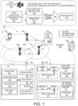
- FIG. 1 is a schematic system diagram illustrating an exemplary wireless network that supports data collection in accordance with embodiments of the current invention.
- Wireless communication network 100 includes one or more fixed base infrastructure units forming a network distributed over a geographical region.
- the base unit may also be referred to as an access point, an access terminal, a base station, a Node-B, an eNode-B (eNB), a gNB, or by other terminology used in the art.
- base stations serve a number of mobile stations within a serving area, for example, a cell, or within a cell sector.
- one or more base stations are coupled to a controller forming an access network that is coupled to one or more core networks.
- gNB 102, gNB 107 and gNB 108 are base stations in the wireless network, the serving area of which may or may not overlap with each other.
- gNB 102 is connected with gNB 107 via Xn interface 121.
- gNB 102 is connected with gNB 108 via Xn interface 122.
- gNB 107 is connected with gNB 108 via Xn interface 123.
- Core network (CN) entity 103 connects with gNB 102 and 107, through NG interface 125 and 126, respectively.
- Network entity CN 109 connects with gNB 108 via NG connection 127.
- Exemplary CN 103 and CN 109 connect to AI server 105 through internet 106.
- AI server 105 is a UE server.
- the UE server can be inside of a mobile network operator (MNO).
- MNO mobile network operator
- the UE server can be outside of the MNO, and it can be also referred as an over-the-top (OTT) server.
- OTT over-the-top
- the UE server is a UE-side OTT server.
- the UE server is a network-side OTT server or a neutral site OTT server. Please note that some of the following examples are described in the context of OTT server, but they can also be applied to other types of UE server.
- Figure 1 further illustrates general data collection framework for the UE(s), the RAN nodes/gNB(s), the CN, and the AI server, such as an OTT server, respectively.
- CN 103 is the backbone of the wireless network and communicates with the UE server via internet 106.
- CN 103 includes the network node/entity/function, such as data collection application function (DCAF), core network (CN), operations, administration, and maintenance (OAM), etc.
- DCAF data collection application function
- CN core network
- OAM operations, administration, and maintenance
- UE performs data collection for AI-ML model.
- Data collection is a process of collecting data by the network nodes, management entity, UE-side server, or neutral server for the purpose of AI/ML model training, data analytics, and inference. Data collection allows data to reach the UE-side or the neutral site (i.e., UE server), and collect sufficient data for model generalization.
- the UE obtains data collection configuration / trigger.
- the UE collects AI-ML related data.
- the UE establishes a data delivery tunnel for the AI-ML related data delivery.
- the UE delivers the AI-ML related data through the established tunnel.
- the UE obtains the assistance information and delivers the assistance information and the AI-ML related data through the established tunnel.
- Figure 1 further illustrates simplified block diagrams of a RAN node / base station, a UE server and a mobile device/UE that supports data collection.
- the gNB / RAN node has an antenna 156, which transmits and receives radio signals.
- An RF transceiver circuit 153 coupled with the antenna 156, receives RF signals from antenna 156, converts them to baseband signals, and sends them to processor 152.
- RF transceiver 153 also converts received baseband signals from processor 152, converts them to RF signals, and sends out to antenna 156.
- Processor 152 processes the received baseband signals and invokes different functional modules to perform features in gNB 107.
- Memory 151 stores program instructions and data 155 to control the operations of the base station/gNB.
- the base station / gNB also includes a set of control modules 157 that carry out functional tasks to communicate with mobile stations. These control modules can be implemented by circuits, software, firmware, or a combination of them.
- Figure 1 also includes simplified block diagrams of a UE, such as UE 101.
- the UE may also be referred to as a mobile station, a mobile terminal, a mobile phone, a smart phone, a wearable device, an IoT device, a tablet, a laptop, or other terminology used in the art.
- the UE performs functions perform data collection for AI-ML model training and includes modules of detection module, configuration module, collection module and delivery module.
- UE interacts with gNB through the air interface.
- the UE has an antenna 166, which transmits and receives radio signals.
- RF transceiver 163 also converts received baseband signals from processor 162, converts them to RF signals, and sends out to antenna 166.
- Processor 162 processes the received baseband signals and invokes different functional modules to perform features in UE 101.
- Memory 161 stores program instructions and data 165 to control the operations of UE 101.
- Antenna 166 sends uplink transmission and receives downlink transmissions to/from antenna 156 of the base station / gNB.
- the UE also includes a set of control modules that carry out functional tasks. These control modules can be implemented by circuits, software, firmware, or a combination of them.
- a detection module 191 receives a data collection request initiated by a UE server, wherein the UE is connected with a radio access network (RAN) node of the wireless network.
- a configuration module 192 obtains data collection configuration from the RAN node, wherein the data collection configuration configures AI-ML model related parameters for the UE.
- a collection module 193 performs data collection to collect AI-ML model related data based on the data collection configuration.
- a delivery module 194 that delivers the collected AI-ML model related data destined to the UE server through a delivery tunnel.
- Figure 1 also includes simplified block diagrams of an UE server, such as UE server 105.
- the UE server has a network interface module 173, which transmits and receives signals / message through the network.
- Processor 172 processes the received messages and invokes different functional modules to perform features in the UE server.
- Memory 171 stores program instructions and data 175 to control the operations of the UE server.
- the UE server also includes a set of control modules 177 that carry out functional tasks to communicate with mobile stations. These control modules can be implemented by circuits, software, firmware, or a combination of them.
- Figure 2 illustrates diagrams for an exemplary process of the data collection to the UE server without RAN awareness in accordance with embodiments of the current invention.
- One or more UEs such as UEs 201a, 201b, and 201c, connect with a RAN node/gNB 202.
- gNB 202 connects with the core network 203.
- Core network 203 includes network functions and/or entities, such as DCAF, OAM and other network functions/entities.
- Core network 203 connects with an UE server 205.
- the data flows from UE 201a /201b/201c to the UE server 205.
- the data is delivered from UE to a network entity/function in CN 203, which forwards the data to the UE server 205.
- the data delivery tunnel is the user plane (UP) tunnel.
- the data delivery tunnel from the UE to the network entity/function in CN 203 and from the network entity/function in CN 203 to the UE server 205 is through control plane (CP) tunnel.
- the AI-ML related data collected are non-standardized / standardized / proprietary data for various models tailored to UE internal and/or external conditions and design choices.
- the design choices include UE resource constraints, radio environment, and/or feature engineering.
- the UE collects AI-ML model related data.
- the collected data includes one or more elements including model input, model ground-truth, quality of the data, and other information, e.g., AI-ML model related data for AI-ML model generalization.
- the UE communicates with the RAN node / gNB for data collection configuration and optionally assistance information.
- the UE and RAN node can communicate through a layer-1 (L1) UCI, a L2 MAC control element (CE), a radio resource control (RRC) message, or a new radio bearer for the AI.
- assistance information is also delivered to the UE server.
- the assistance information includes one or more elements comprising use case for the AI-ML model related data, functionality of the AI-ML model related data, scenario information, location information, and RAN configuration information for the AI-ML model related data.
- authentication is performed for the AI-ML related data delivery.
- the authentication can be performed by the core network entity/function, the OAM, or the UE server.
- the network node/entity/function e.g., DCAF, CN, OAM, etc.
- the network node/entity/function e.g., DCAF, CN, OAM, etc.
- the network node/entity/function e.g., DCAF, CN, OAM, etc.
- the network node/entity/function also determines what types of data are allowed to be collected and delivered to the UE server.
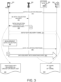
- Figure 3 illustrates an exemplary flow of data collection triggering from the UE server to UE without a network node involvement in accordance with embodiments of the current invention.
- the data collection triggering/request is from the UE server to UE through the application layer.
- UE 301 connects with RAN node 302 and CN 303, which connects with an UE server 304.
- UE server 304 sends data collection request directly to UE 301.
- the data collection request is sent through an application layer message.
- UE 301 further sends the data collection request to RAN node 302.
- the data collection request is indicated from the application layer to RRC layer, through which data collection request is sent from the UE to network.
- the data collection request to the RAN node can be L1/L2 signalling.
- RAN node 302 provides data collection configuration/assistance information replying on UE requests.
- the data collection configuration and/or the assistance information is delivered by RAN node 302 through unicast or groupcast.
- the RAN node provides data collection configuration/ assistance information for each UE.
- the RAN node provides data collection configuration/ assistance information for a group of UEs.
- the data delivery tunnel is set up between UE and the UE server. In one embodiment 330, the data delivery tunnel is the UP tunnel or a CP tunnel.
- UE 301 performs measurement based on data collection configuration from the RAN node 302.
- UE 301 sends the data collection response to the UE server 304.
- UE 301 attaches the assistant information received from the RAN node 302 to the collected data.
- UE 301 delivers the collected data (attached with assistance information) to the UE server 304 through the data delivery tunnel.
- FIG. 4 illustrates an exemplary process of data collection triggering from the UE server to the CN in accordance with embodiments of the current invention.
- UE 401 connects with a RAN node 402 to one or more CN entities 403, which connects with an UE server 404.
- the CN entity is a network node/entity/function (e.g., DCAF, CN, OAM, etc.)
- UE server 404 sends the data collection request to a CN entity 403.
- CN entity 403 further sends the data collection request to UE 401.
- CN entity 403, in response to the data collection request sends data collection response to the UE server 404.
- the data delivery tunnel is set up between CN entity 403 and UE server 404. In one embodiment, the data delivery tunnel is UP tunnel.
- CN entity 403 sends the data collection assistance information request to the RAN node 402.
- RAN node 402 provides assistance information to CN entity 403 at step 446.
- CN entity 403 performs authorization check and determine whether data collection and data delivery to the UE server is allowed or not.
- CN entity 403 also determines what types of data are allowed to be collected and delivered to the UE server.
- RAN node 402 provides assistance information relying on the business agreement between RAN and UE server.
- the RAN node 402 sends data collection configuration and triggering to UE 401.
- UE 401 performs data collection based on data collection configuration.
- UE 401 sends configuration complete message to RAN node 402.
- UE 401 sends data collection response to CN entity 403.
- UE 401 delivers the collected data to CN entity 403.
- UE 401 interacts with CN entity 403 through the NAS signalling (CP tunnel).
- CP tunnel NAS signalling
- UE 401 interacts with CN entity 403 through the application layer (UP tunnel).
- CN entity 403 attaches assistance information to the collected data received from UEs, such as UE 401.
- CN entity 403 delivers the collected data (attached with assistance information) to the UE server 404 through data delivery tunnel after authorization check.
- Figure 5 illustrates an exemplary flow of data collection without RAN awareness triggering from the UE server to the CN entity and from the UE server to UE in accordance with embodiments of the current invention.
- UE 501 connects with RAN node 502 and CN entity 503, which connects with an UE server 504.
- the data collection triggering/ request from the UE server 504 is sent to CN entity 503.
- CN entity 503 sends data collection response to UE server 504.
- the data collection triggering / request is sent from UE server 505 to UE 501 through the application layer.
- the data delivery tunnel is set up between UE 501 and the UE server 505.
- the data delivery tunnel is the UP tunnel.
- CN entity 503 sends the data collection and assistance information request to the RAN node 502.
- RAN node 502 provides assistance information to CN entity 503 for authorization check.
- CN entity 503 performs authorization check and determine whether data collection and data delivery to the UE server is allowed or not.
- CN entity 503 also determines what types of data are allowed to be collected and delivered to the UE server 504.
- RAN node 502 sends data collection configuration and trigger to UE 501.
- UE 501 performs data collection based on the data collection configuration.
- UE 501 sends configuration complete to RAN node 502.
- CN 503 sends data collection request and assistance information to UE after authorization check.
- UE 501 sends data collection response to the CN entity 503.
- UE 501 attaches assistance information with the collected data.
- UE 501 sends the collected data together with the assistance information to the UE server 505 through data delivery tunnel.
- Figure 6 illustrates an exemplary flow chart for the UE to perform the AI-ML data collection in accordance with embodiments of the current invention.
- the UE receives a data collection request initiated by a UE server, wherein the UE is connected with a radio access network (RAN) node of the wireless network.
- the UE obtains data collection configuration from the RAN node, wherein the data collection configuration configures AI-ML model related parameters for the UE.
- the UE performs data collection to collect AI-ML model related data based on the data collection configuration.
- the UE delivers the collected AI-ML model related data destined to the UE server through a delivery tunnel.
- RAN radio access network
- Figure 7 illustrates an exemplary flow chart for the UE server to perform the AI-ML data collection in accordance with embodiments of the current invention.
- the UE server initiates a data collection request destined to the one or more UEs, wherein the data collection request initiates data collection by the one or more UEs for AI-ML model used by the one or more UEs.
- the OTT server receives one or more data collection responses.
- the UE server receives AI-ML model related data and assistance information through a data tunnel connected with the wireless network.
Landscapes
- Engineering & Computer Science (AREA)
- Signal Processing (AREA)
- Computer Networks & Wireless Communication (AREA)
- Software Systems (AREA)
- Artificial Intelligence (AREA)
- Computer Vision & Pattern Recognition (AREA)
- Evolutionary Computation (AREA)
- Medical Informatics (AREA)
- Databases & Information Systems (AREA)
- Theoretical Computer Science (AREA)
- General Physics & Mathematics (AREA)
- Mathematical Physics (AREA)
- General Engineering & Computer Science (AREA)
- Computing Systems (AREA)
- Physics & Mathematics (AREA)
- Data Mining & Analysis (AREA)
- Mobile Radio Communication Systems (AREA)
Abstract
Apparatus and methods are provided for data collection general framework for AI-ML model training. In one novel aspect, the UE server sends the data collection request/triggering to UE through the application layer without network involvement with the general frame for data collection including data collection triggering, data collection configuration, measurements, and data delivery. In one embodiment, the assistance information is received from the RAN node with unicast or groupcast. In another embodiment, the UE delivers assistance information with the collected AI-ML model related data to deliver to the UE server. In one novel aspect, the UE server initiates a data collection request destined to the one or more UEs and receives one or more data collection responses and AI-ML model related data and assistance information through a data tunnel connected with the wireless network.
Description
- The disclosed embodiments relate generally to wireless communication, and, more particularly, to data collection without radio access network (RAN) awareness.
- Artificial Intelligence (AI) and Machine Leaning (ML) have been widely used in wireless networks to improve performance, user experience, and reduce complexity/overhead. In the conventional network of the 3rd generation partnership project (3GPP) 5G new radio (NR), AI/ML technology is leveraged to address challenges due to the increased complexity of foreseen deployments over the air interface, both for the network and UEs. Data collection is a crucial step in AI/ML life cycle management (LCM), which provides the foundation for creating effective and accurate models.
- In wireless AI technology, offline training is the most feasible option and serves as the foundation for wireless AI. Regarding user equipment (UE)-side models, the training can take place on the UE-side or a neutral site. However, it is not practical to perform UE-side model training within the UE due to the lack of a suitable training environment. This includes but is not limited to data availability, storage capacity, computational capacity, and compilation capabilities. For effective offline model training, the data collection solution should be designed to "reach" the UE-side or a neutral site, such as over the top (OTT) server. And a large amount of non-standardized/proprietary data should be collected that can be tailored to various UE internal/external conditions and design choices (e.g., UE resource constraints, radio environment, feature engineering). Besides, the collected data should be sufficient for well model generalization.
- Improvements and enhancements are required for data collection without RAN awareness.
- Apparatus and methods are provided for data collection general framework for AI-ML model training. In one novel aspect, general frame for data collection includes data collection triggering, data collection configuration, measurements, and data delivery. In one embodiment, the OTT server (UE server) sends the data collection request/triggering to UE through the application layer without network involvement. The UE server is a UE-side OTT server, a network-side OTT server or a neutral site OTT server. In one embodiment, the UE receives a data collection request initiated by a UE server, obtains data collection configuration from the RAN node, wherein the data collection configuration configures AI-ML model related parameters for the UE, performs data collection to collect the AI-ML related data based on the data collection configuration, and delivers the collected AI-ML model related data destined to the UE server through a delivery tunnel. In one embodiment, the UE receives the data collection request directly from the UE server through an application layer message, and wherein the delivery tunnel is established between the UE and the UE server. In another embodiment, the UE sends a UE data request to the RAN node and receives the data collection configuration and assistance information from the RAN node. In one embodiment, the assistance information includes one or more elements comprising: use case for the AI-ML model related data, functionality of the AI-ML model related data, scenario information, location information, and RAN configuration information for the AI-ML model related data. In one embodiment, the assistance information is received from the RAN node with unicast or groupcast. In another embodiment, the UE delivers assistance information with the collected AI-ML model related data to deliver to the UE server. In yet another embodiment, the delivery tunnel established between the UE and the UE server is a user plane (UP) tunnel or a control plane (CP) tunnel. In one embodiment, the UE receives the data collection configuration together with a data collection trigger from the RAN node, and wherein the delivery tunnel includes a data path established between the UE and the network entity and a tunnel between the network entity and the UE server. In another embodiment, the data path between the UE and the network entity is a CP tunnel through a Non-Access-Stratum (NAS) layer or a UP tunnel through an application layer. In one embodiment, the UE receives the data collection request with assistance information from a network entity of the wireless network.
- In one novel aspect, the UE server initiates a data collection request destined to the one or more UEs, wherein the data collection request initiates data collection by the one or more UEs for AI-ML model used by the one or more UEs, receives one or more data collection responses and AI-ML model related data and assistance information through a data tunnel connected with the wireless network. In one embodiment, the data collection request is sent to the one or more UEs directly through an application layer message or to a network entity of the wireless network. In another embodiment, the assistance information is attached to the AI-ML model related data by corresponding UEs or by a network entity of the wireless network. In one embodiment, the data tunnel is a direct user plane (UP) tunnel with corresponding UE, a direct control plane (CP) tunnel with corresponding UE, a UP tunnel with a network entity together with a data path to corresponding UE, or a CP tunnel with a network entity together with a data path to corresponding UE.
- This summary does not purport to define the invention. The invention is defined by the claims.
- The accompanying drawings, where like numerals indicate like components, illustrate embodiments of the invention.
-
Figure 1 is a schematic system diagram illustrating an exemplary wireless network that supports data collection in accordance with embodiments of the current invention. -
Figure 2 illustrates diagrams for an exemplary process of the data collection to the UE server without RAN awareness in accordance with embodiments of the current invention. -
Figure 3 illustrates an exemplary flow of data collection triggering from the UE server to UE without a network node involvement in accordance with embodiments of the current invention. -
Figure 4 illustrates an exemplary process of data collection triggering from the UE server to the CN in accordance with embodiments of the current invention. -
Figure 5 illustrates an exemplary flow of data collection without RAN awareness triggering from the UE server to the CN entity and from the UE server to UE in accordance with embodiments of the current invention. -
Figure 6 illustrates an exemplary flow chart for the UE to perform the AI-ML data collection in accordance with embodiments of the current invention. -
Figure 7 illustrates an exemplary flow chart for the UE server to perform the AI-ML data collection in accordance with embodiments of the current invention. - Reference will now be made in detail to some embodiments of the invention, examples of which are illustrated in the accompanying drawings.
- Several aspects of telecommunication systems will now be presented with reference to various apparatus and methods. These apparatus and methods will be described in the following detailed description and illustrated in the accompanying drawings by various blocks, components, circuits, processes, algorithms, etc. (Collectively referred to as "elements"). These elements may be implemented using electronic hardware, computer software, or any combination thereof. Whether such elements are implemented as hardware or software depends upon the particular application and design constraints imposed on the overall system.
-
Figure 1 is a schematic system diagram illustrating an exemplary wireless network that supports data collection in accordance with embodiments of the current invention.Wireless communication network 100 includes one or more fixed base infrastructure units forming a network distributed over a geographical region. The base unit may also be referred to as an access point, an access terminal, a base station, a Node-B, an eNode-B (eNB), a gNB, or by other terminology used in the art. As an example, base stations serve a number of mobile stations within a serving area, for example, a cell, or within a cell sector. In some systems, one or more base stations are coupled to a controller forming an access network that is coupled to one or more core networks. gNB 102, gNB 107 and gNB 108 are base stations in the wireless network, the serving area of which may or may not overlap with each other. gNB 102 is connected with gNB 107 viaXn interface 121. gNB 102 is connected with gNB 108 viaXn interface 122. gNB 107 is connected with gNB 108 viaXn interface 123. Core network (CN)entity 103 connects with gNB 102 and 107, throughNG interface connection 127. Exemplary CN 103 and CN 109 connect toAI server 105 throughinternet 106. CN 103 and CN 109 includes core components such as user plane function (UPF) and access and mobility management function (AMF). In one embodiment,AI server 105 is a UE server. According to some examples, the UE server can be inside of a mobile network operator (MNO). According to some other examples, the UE server can be outside of the MNO, and it can be also referred as an over-the-top (OTT) server. In one example, the UE server is a UE-side OTT server. In another example, the UE server is a network-side OTT server or a neutral site OTT server. Please note that some of the following examples are described in the context of OTT server, but they can also be applied to other types of UE server. -
Figure 1 further illustrates general data collection framework for the UE(s), the RAN nodes/gNB(s), the CN, and the AI server, such as an OTT server, respectively.CN 103 is the backbone of the wireless network and communicates with the UE server viainternet 106. In one embodiment,CN 103 includes the network node/entity/function, such as data collection application function (DCAF), core network (CN), operations, administration, and maintenance (OAM), etc. - In one
novel aspect 180, UE performs data collection for AI-ML model. Data collection is a process of collecting data by the network nodes, management entity, UE-side server, or neutral server for the purpose of AI/ML model training, data analytics, and inference. Data collection allows data to reach the UE-side or the neutral site (i.e., UE server), and collect sufficient data for model generalization. Atstep 181, the UE obtains data collection configuration / trigger. Atstep 182, the UE collects AI-ML related data. Atstep 184, the UE establishes a data delivery tunnel for the AI-ML related data delivery. Atstep 185, the UE delivers the AI-ML related data through the established tunnel. In one embodiment, atstep 183, the UE obtains the assistance information and delivers the assistance information and the AI-ML related data through the established tunnel. -
Figure 1 further illustrates simplified block diagrams of a RAN node / base station, a UE server and a mobile device/UE that supports data collection. The gNB / RAN node has anantenna 156, which transmits and receives radio signals. AnRF transceiver circuit 153, coupled with theantenna 156, receives RF signals fromantenna 156, converts them to baseband signals, and sends them toprocessor 152.RF transceiver 153 also converts received baseband signals fromprocessor 152, converts them to RF signals, and sends out toantenna 156.Processor 152 processes the received baseband signals and invokes different functional modules to perform features in gNB 107.Memory 151 stores program instructions anddata 155 to control the operations of the base station/gNB. The base station / gNB also includes a set ofcontrol modules 157 that carry out functional tasks to communicate with mobile stations. These control modules can be implemented by circuits, software, firmware, or a combination of them. -
Figure 1 also includes simplified block diagrams of a UE, such asUE 101. The UE may also be referred to as a mobile station, a mobile terminal, a mobile phone, a smart phone, a wearable device, an IoT device, a tablet, a laptop, or other terminology used in the art. The UE performs functions perform data collection for AI-ML model training and includes modules of detection module, configuration module, collection module and delivery module. UE interacts with gNB through the air interface. The UE has anantenna 166, which transmits and receives radio signals. AnRF transceiver circuit 163, coupled with the antenna, receives RF signals fromantenna 166, converts them to baseband signals, and sends them toprocessor 162.RF transceiver 163 also converts received baseband signals fromprocessor 162, converts them to RF signals, and sends out toantenna 166.Processor 162 processes the received baseband signals and invokes different functional modules to perform features inUE 101.Memory 161 stores program instructions anddata 165 to control the operations ofUE 101.Antenna 166 sends uplink transmission and receives downlink transmissions to/fromantenna 156 of the base station / gNB. - The UE also includes a set of control modules that carry out functional tasks. These control modules can be implemented by circuits, software, firmware, or a combination of them. A
detection module 191 receives a data collection request initiated by a UE server, wherein the UE is connected with a radio access network (RAN) node of the wireless network. A configuration module 192 obtains data collection configuration from the RAN node, wherein the data collection configuration configures AI-ML model related parameters for the UE. Acollection module 193 performs data collection to collect AI-ML model related data based on the data collection configuration. Adelivery module 194 that delivers the collected AI-ML model related data destined to the UE server through a delivery tunnel. -
Figure 1 also includes simplified block diagrams of an UE server, such asUE server 105. The UE server has anetwork interface module 173, which transmits and receives signals / message through the network.Processor 172 processes the received messages and invokes different functional modules to perform features in the UE server. Memory 171 stores program instructions anddata 175 to control the operations of the UE server. The UE server also includes a set ofcontrol modules 177 that carry out functional tasks to communicate with mobile stations. These control modules can be implemented by circuits, software, firmware, or a combination of them. -
Figure 2 illustrates diagrams for an exemplary process of the data collection to the UE server without RAN awareness in accordance with embodiments of the current invention. One or more UEs, such as UEs 201a, 201b, and 201c, connect with a RAN node/gNB 202.gNB 202 connects with thecore network 203.Core network 203 includes network functions and/or entities, such as DCAF, OAM and other network functions/entities.Core network 203 connects with anUE server 205. In one embodiment, the data flows fromUE 201a /201b/201c to theUE server 205. In one embodiment, the data is delivered from UE to a network entity/function inCN 203, which forwards the data to theUE server 205. In one embodiment, the data delivery tunnel is the user plane (UP) tunnel. In another embodiment, the data delivery tunnel from the UE to the network entity/function inCN 203 and from the network entity/function inCN 203 to theUE server 205 is through control plane (CP) tunnel. In oneembodiment 210, the AI-ML related data collected are non-standardized / standardized / proprietary data for various models tailored to UE internal and/or external conditions and design choices. In one embodiment, the design choices include UE resource constraints, radio environment, and/or feature engineering. In one embodiment, the UE collects AI-ML model related data. The collected data includes one or more elements including model input, model ground-truth, quality of the data, and other information, e.g., AI-ML model related data for AI-ML model generalization. At oneembodiment 220, the UE communicates with the RAN node / gNB for data collection configuration and optionally assistance information. The UE and RAN node can communicate through a layer-1 (L1) UCI, a L2 MAC control element (CE), a radio resource control (RRC) message, or a new radio bearer for the AI. In oneembodiment 230, assistance information is also delivered to the UE server. The assistance information includes one or more elements comprising use case for the AI-ML model related data, functionality of the AI-ML model related data, scenario information, location information, and RAN configuration information for the AI-ML model related data. In oneembodiment 250, authentication is performed for the AI-ML related data delivery. The authentication can be performed by the core network entity/function, the OAM, or the UE server. In one embodiment, the network node/entity/function (e.g., DCAF, CN, OAM, etc.) performs authorization check and determine whether data collection and data delivery to the UE server is allowed or not. In one embodiment, the network node/entity/function (e.g., DCAF, CN, OAM, etc.) also determines what types of data are allowed to be collected and delivered to the UE server. -
Figure 3 illustrates an exemplary flow of data collection triggering from the UE server to UE without a network node involvement in accordance with embodiments of the current invention. In one embodiment, the data collection triggering/request is from the UE server to UE through the application layer.UE 301 connects withRAN node 302 andCN 303, which connects with anUE server 304. Atstep 311,UE server 304 sends data collection request directly toUE 301. In one embodiment, the data collection request is sent through an application layer message. In one embodiment, atstep 321,UE 301 further sends the data collection request toRAN node 302. In one embodiment, the data collection request is indicated from the application layer to RRC layer, through which data collection request is sent from the UE to network. In one embodiment, the data collection request to the RAN node can be L1/L2 signalling. In one embodiment, at step 322,RAN node 302 provides data collection configuration/assistance information replying on UE requests. In oneembodiment 320, the data collection configuration and/or the assistance information is delivered byRAN node 302 through unicast or groupcast. In one embodiment, the RAN node provides data collection configuration/ assistance information for each UE. In one embodiment, the RAN node provides data collection configuration/ assistance information for a group of UEs. Atstep 331, the data delivery tunnel is set up between UE and the UE server. In oneembodiment 330, the data delivery tunnel is the UP tunnel or a CP tunnel. Atstep 341,UE 301 performs measurement based on data collection configuration from theRAN node 302. Atstep 351,UE 301 sends the data collection response to theUE server 304. In one embodiment,UE 301 attaches the assistant information received from theRAN node 302 to the collected data. Atstep 361,UE 301 delivers the collected data (attached with assistance information) to theUE server 304 through the data delivery tunnel. -
Figure 4 illustrates an exemplary process of data collection triggering from the UE server to the CN in accordance with embodiments of the current invention.UE 401 connects with aRAN node 402 to one ormore CN entities 403, which connects with anUE server 404. In one embodiment, the CN entity is a network node/entity/function (e.g., DCAF, CN, OAM, etc.) Atstep 411,UE server 404 sends the data collection request to aCN entity 403. Atstep 431,CN entity 403 further sends the data collection request toUE 401. Atstep 412,CN entity 403, in response to the data collection request, sends data collection response to theUE server 404. Atstep 421, the data delivery tunnel is set up betweenCN entity 403 andUE server 404. In one embodiment, the data delivery tunnel is UP tunnel. - At
step 432,CN entity 403 sends the data collection assistance information request to theRAN node 402.RAN node 402 provides assistance information toCN entity 403 atstep 446. In one embodiment,CN entity 403 performs authorization check and determine whether data collection and data delivery to the UE server is allowed or not. In one embodiment,CN entity 403 also determines what types of data are allowed to be collected and delivered to the UE server. In one embodiment,RAN node 402 provides assistance information relying on the business agreement between RAN and UE server. At step 433, theRAN node 402 sends data collection configuration and triggering toUE 401. Atstep 441,UE 401 performs data collection based on data collection configuration. Atstep 445,UE 401 sends configuration complete message toRAN node 402. Atstep 451,UE 401 sends data collection response toCN entity 403. Atstep 461,UE 401 delivers the collected data toCN entity 403. In one embodiment,UE 401 interacts withCN entity 403 through the NAS signalling (CP tunnel). In one embodiment,UE 401 interacts withCN entity 403 through the application layer (UP tunnel). In one embodiment, atstep 462,CN entity 403 attaches assistance information to the collected data received from UEs, such asUE 401. Atstep 464,CN entity 403 delivers the collected data (attached with assistance information) to theUE server 404 through data delivery tunnel after authorization check. -
Figure 5 illustrates an exemplary flow of data collection without RAN awareness triggering from the UE server to the CN entity and from the UE server to UE in accordance with embodiments of the current invention.UE 501 connects withRAN node 502 andCN entity 503, which connects with anUE server 504. Atstep 511, the data collection triggering/ request from theUE server 504 is sent toCN entity 503. At step 512,CN entity 503 sends data collection response toUE server 504. In one embodiment, atstep 510, the data collection triggering / request is sent from UE server 505 toUE 501 through the application layer. In one embodiment, atstep 521, the data delivery tunnel is set up betweenUE 501 and the UE server 505. In one embodiment, the data delivery tunnel is the UP tunnel. Atstep 531,CN entity 503 sends the data collection and assistance information request to theRAN node 502. At step 546, in response,RAN node 502 provides assistance information toCN entity 503 for authorization check. In one embodiment,CN entity 503 performs authorization check and determine whether data collection and data delivery to the UE server is allowed or not. In one embodiment,CN entity 503 also determines what types of data are allowed to be collected and delivered to theUE server 504. - At
step 532,RAN node 502 sends data collection configuration and trigger toUE 501. Atstep 541,UE 501 performs data collection based on the data collection configuration. Atstep 545,UE 501 sends configuration complete toRAN node 502. In one embodiment, atstep 551,CN 503 sends data collection request and assistance information to UE after authorization check. Atstep 552,UE 501 sends data collection response to theCN entity 503. In one embodiment,UE 501 attaches assistance information with the collected data. Atstep 561,UE 501 sends the collected data together with the assistance information to the UE server 505 through data delivery tunnel. -
Figure 6 illustrates an exemplary flow chart for the UE to perform the AI-ML data collection in accordance with embodiments of the current invention. Atstep 601, the UE receives a data collection request initiated by a UE server, wherein the UE is connected with a radio access network (RAN) node of the wireless network. Atstep 602, the UE obtains data collection configuration from the RAN node, wherein the data collection configuration configures AI-ML model related parameters for the UE. Atstep 603, the UE performs data collection to collect AI-ML model related data based on the data collection configuration. Atstep 604, the UE delivers the collected AI-ML model related data destined to the UE server through a delivery tunnel. -
Figure 7 illustrates an exemplary flow chart for the UE server to perform the AI-ML data collection in accordance with embodiments of the current invention. Atstep 701, the UE server initiates a data collection request destined to the one or more UEs, wherein the data collection request initiates data collection by the one or more UEs for AI-ML model used by the one or more UEs. Atstep 702, the OTT server receives one or more data collection responses. Atstep 703, the UE server receives AI-ML model related data and assistance information through a data tunnel connected with the wireless network. - Although the present invention has been described in connection with certain specific embodiments for instructional purposes, the present invention is not limited thereto. Accordingly, various modifications, adaptations, and combinations of various features of the described embodiments can be practiced without departing from the scope of the invention as set forth in the claims.
Claims (15)
- A method for a user equipment (UE) using artificial intelligence - machine learning (AI-ML) model in a wireless network comprising:receiving, by the UE, a data collection request initiated by a UE server, wherein the UE is connected with a radio access network (RAN) node of the wireless network;obtaining data collection configuration from the RAN node, wherein the data collection configuration configures AI-ML model related parameters for the UE;performing data collection to collect AI-ML model related data based on the data collection configuration; anddelivering the collected AI-ML model related data destined to the UE server through a delivery tunnel.
- The method of claim 1, wherein the UE receives the data collection request directly from the UE server through an application layer message, and wherein the delivery tunnel is established between the UE and the UE server.
- The method of claim 2, further comprising:
sending a UE data collection request to the RAN node; and
receiving the data collection configuration and assistance information from the RAN node. - The method of claim 3, wherein the assistance information includes one or more elements comprising: use case for the AI-ML model related data, functionality of the AI-ML model related data, scenario information, location information, and RAN configuration information for the AI-ML model related data;
and/or wherein the assistance information is received from the RAN node with unicast or groupcast. - The method of claim 3, wherein the UE delivers the assistance information with the collected AI-ML model related data destined to the UE server.
- The method of claim 2, wherein the delivery tunnel established between the UE and the UE server is a user plane (UP) tunnel or a control plane (CP) tunnel.
- The method of claim 1, wherein the UE receives the data collection request from a network entity of the wireless network.
- The method of claim 7, wherein the UE receives the data collection configuration together with a data collection trigger from the RAN node, and wherein the delivery tunnel includes a data path established between the UE and the network entity and a tunnel between the network entity and the UE server.
- The method of claim 7, wherein the data path between the UE and the network entity is a CP tunnel through a Non-Access-Stratum (NAS) layer or a UP tunnel through an application layer.
- The method of claim 1, where the UE receives the data collection request with assistance information from a network entity of the wireless network.
- The method of claim 10, wherein the UE receives the data collection configuration together with a data collection trigger from the RAN node, and wherein the delivery tunnel is established between the UE and the UE server, and wherein the delivery tunnel is a user plane (UP) tunnel or a control plane (CP) tunnel.
- The method of claim 10, wherein the assistance information includes one or more elements comprising: use case for the AI-ML model related data, functionality of the AI-ML model related data, scenario information, location information, and RAN configuration information for the AI-ML model related data.
- The method of claim 1, wherein the UE communicates with the RAN node through layer-1 (L1) uplink control information (UCI), L2 MAC control element (CE), radio resource control (RRC) message or a new radio bearer for AI;
and/or wherein the data collection configuration is received from the RAN node with unicast or groupcast. - A method for a user equipment (UE) server providing artificial intelligence - machine learning (AI-ML) model for one or more UE in a wireless network comprising:initiating, by the UE server, a data collection request destined to the one or more UEs, wherein the data collection request initiates data collection by the one or more UEs for AI-ML model used by the one or more UEs;receiving one or more data collection responses; andreceiving AI-ML model related data and assistance information through a data tunnel connected with the wireless network;wherein, for example, the data collection request is sent to the one or more UEs directly through an application layer message or to a network entity of the wireless network;and/or wherein, for example, the assistance information is attached to the AI-ML model related data by corresponding UEs or by a network entity of the wireless network;and/or wherein, for example, the data tunnel is a direct user plane (UP) tunnel with corresponding UE, a direct control plane (CP) tunnel with corresponding UE, a UP tunnel with a network entity together with a data path to corresponding UE, or a CP tunnel with a network entity together with a data path to corresponding UE.
- A user equipment (UE), comprising:a transceiver that transmits and receives radio frequency (RF) signal in a wireless network;a detection module that receives a data collection request initiated by a UE server, wherein the UE is connected with a radio access network (RAN) node of the wireless network;a configuration module that obtains data collection configuration from the RAN node, wherein the data collection configuration configures AI-ML model related parameters for the UE;a collection module that performs data collection to collect AI-ML model related data based on the data collection configuration; anda delivery module that delivers the collected AI-ML model related data destined to the UE server through a delivery tunnel.
Applications Claiming Priority (2)
| Application Number | Priority Date | Filing Date | Title |
|---|---|---|---|
| PCT/CN2023/111753 WO2025030371A1 (en) | 2023-08-08 | 2023-08-08 | Methods and apparatus of general framework for data collection without ran awareness |
| CN202410879182.8A CN119485272A (en) | 2023-08-08 | 2024-07-01 | Method, user device and storage medium for performing AI-ML data collection |
Publications (1)
| Publication Number | Publication Date |
|---|---|
| EP4507261A1 true EP4507261A1 (en) | 2025-02-12 |
Family
ID=92263987
Family Applications (1)
| Application Number | Title | Priority Date | Filing Date |
|---|---|---|---|
| EP24193452.0A Pending EP4507261A1 (en) | 2023-08-08 | 2024-08-07 | Methods and apparatus of general framework for data collection without ran awareness |
Country Status (3)
| Country | Link |
|---|---|
| US (1) | US20250056291A1 (en) |
| EP (1) | EP4507261A1 (en) |
| TW (1) | TW202508316A (en) |
Citations (1)
| Publication number | Priority date | Publication date | Assignee | Title |
|---|---|---|---|---|
| WO2022229233A1 (en) * | 2021-04-30 | 2022-11-03 | Telefonaktiebolaget Lm Ericsson (Publ) | User equipment (ue) feedback for improved energy efficiency configuration |
-
2024
- 2024-07-31 TW TW113128505A patent/TW202508316A/en unknown
- 2024-08-03 US US18/793,803 patent/US20250056291A1/en active Pending
- 2024-08-07 EP EP24193452.0A patent/EP4507261A1/en active Pending
Patent Citations (1)
| Publication number | Priority date | Publication date | Assignee | Title |
|---|---|---|---|---|
| WO2022229233A1 (en) * | 2021-04-30 | 2022-11-03 | Telefonaktiebolaget Lm Ericsson (Publ) | User equipment (ue) feedback for improved energy efficiency configuration |
Non-Patent Citations (3)
| Title |
|---|
| ERICSSON: "Data collection for AI/ML", vol. 3GPP RAN 2, no. Incheon, South Korea; 20230522 - 20230526, 12 May 2023 (2023-05-12), XP052391127, Retrieved from the Internet <URL:https://ftp.3gpp.org/tsg_ran/WG2_RL2/TSGR2_122/Docs/R2-2306451.zip R2-2306451 - Data Collection for AIML.docx> [retrieved on 20230512] * |
| ERICSSON: "Discussion on general aspects of AIML framework", vol. 3GPP RAN 1, no. Online; 20230417 - 20230426, 6 April 2023 (2023-04-06), XP052352359, Retrieved from the Internet <URL:https://ftp.3gpp.org/tsg_ran/WG1_RL1/TSGR1_112b-e/Docs/R1-2302877.zip R1-2302877 Discussion on general aspects of AIML framework.docx> [retrieved on 20230406] * |
| YUANYUAN ZHANG ET AL: "Discussion on general aspects of AI/ML LCM", vol. RAN WG1, no. Incheon, KR; 20230522 - 20230526, 15 May 2023 (2023-05-15), XP052311124, Retrieved from the Internet <URL:https://www.3gpp.org/ftp/TSG_RAN/WG1_RL1/TSGR1_113/Docs/R1-2305696.zip R1-2305696.docx> [retrieved on 20230515] * |
Also Published As
| Publication number | Publication date |
|---|---|
| TW202508316A (en) | 2025-02-16 |
| US20250056291A1 (en) | 2025-02-13 |
Similar Documents
| Publication | Publication Date | Title |
|---|---|---|
| EP4184956A1 (en) | Location measurement data reporting method and device, terminal and storage medium | |
| US11212784B2 (en) | Apparatus and method for combined area update and request for on-demand system information in wireless communications | |
| EP4657916A1 (en) | Communication method and apparatus | |
| EP4351225A2 (en) | Method, apparatus and device for allowing terminal to move between 4g and 5g networks | |
| US11425764B2 (en) | Communication method and communications apparatus for reporting establishment causes | |
| US20260046811A1 (en) | Method and apparatus of user equipment (ue) location estimation | |
| US9241352B2 (en) | Method for establishing a connection between a node of a communication system and a node of a data service network in a wireless communication system | |
| CN110419242B (en) | Method, device and storage medium for establishing aggregation connection | |
| EP4591542A1 (en) | Ue initiated model-updates for two-sided ai/ml model | |
| EP4503716A1 (en) | Ue-side data collection with ran awareness for wireless communication systems | |
| WO2023225932A1 (en) | METHOD AND APPARATUS OF SUPPORTING QUALITY OF EXPERIENCE (QoE) MEASUREMENT COLLECTION | |
| CN120457712A (en) | Local sensor integration for integrated sensing and communication | |
| US20250056291A1 (en) | Methods and apparatus of general framework for data collection without ran awareness | |
| EP4418619A1 (en) | Methods and apparatus of general framework for model/functionality identification | |
| CN107949016A (en) | The method for building up and relevant device of dedicated bearer | |
| CN115119155A (en) | A kind of method, device and storage medium for updating terminal PLMN ID in handover | |
| WO2024168831A1 (en) | Methods and apparatus of general framework for model/functionality identification | |
| EP4554278A2 (en) | Power saving in cellular communication networks | |
| CN121729912A (en) | Information sending and receiving method and device | |
| CN119485272A (en) | Method, user device and storage medium for performing AI-ML data collection | |
| CN119450514A (en) | Method for performing data collection, user equipment and storage medium | |
| EP3855858A1 (en) | Improvements for admission control and network sharing in cellular communication networks | |
| WO2025102963A1 (en) | Methods and apparatus for model transfer/delivery for wireless communication systems | |
| WO2026097453A1 (en) | Methods and apparatus to support data collection configuration and logged data during ue mobility | |
| CN115734247A (en) | Communication method and device |
Legal Events
| Date | Code | Title | Description |
|---|---|---|---|
| PUAI | Public reference made under article 153(3) epc to a published international application that has entered the european phase |
Free format text: ORIGINAL CODE: 0009012 |
|
| STAA | Information on the status of an ep patent application or granted ep patent |
Free format text: STATUS: THE APPLICATION HAS BEEN PUBLISHED |
|
| AK | Designated contracting states |
Kind code of ref document: A1 Designated state(s): AL AT BE BG CH CY CZ DE DK EE ES FI FR GB GR HR HU IE IS IT LI LT LU LV MC ME MK MT NL NO PL PT RO RS SE SI SK SM TR |
|
| STAA | Information on the status of an ep patent application or granted ep patent |
Free format text: STATUS: REQUEST FOR EXAMINATION WAS MADE |
|
| 17P | Request for examination filed |
Effective date: 20250811 |