EP4507139A1 - Wire harness product clamping device and heat shrink machine - Google Patents
Wire harness product clamping device and heat shrink machine Download PDFInfo
- Publication number
- EP4507139A1 EP4507139A1 EP24193313.4A EP24193313A EP4507139A1 EP 4507139 A1 EP4507139 A1 EP 4507139A1 EP 24193313 A EP24193313 A EP 24193313A EP 4507139 A1 EP4507139 A1 EP 4507139A1
- Authority
- EP
- European Patent Office
- Prior art keywords
- pair
- wire harness
- cantilevers
- clamping device
- moved
- Prior art date
- Legal status (The legal status is an assumption and is not a legal conclusion. Google has not performed a legal analysis and makes no representation as to the accuracy of the status listed.)
- Pending
Links
Images




Classifications
-
- H—ELECTRICITY
- H01—ELECTRIC ELEMENTS
- H01R—ELECTRICALLY-CONDUCTIVE CONNECTIONS; STRUCTURAL ASSOCIATIONS OF A PLURALITY OF MUTUALLY-INSULATED ELECTRICAL CONNECTING ELEMENTS; COUPLING DEVICES; CURRENT COLLECTORS
- H01R4/00—Electrically-conductive connections between two or more conductive members in direct contact, i.e. touching one another; Means for effecting or maintaining such contact; Electrically-conductive connections having two or more spaced connecting locations for conductors and using contact members penetrating insulation
- H01R4/70—Insulation of connections
- H01R4/72—Insulation of connections using a heat shrinking insulating sleeve
-
- H—ELECTRICITY
- H01—ELECTRIC ELEMENTS
- H01B—CABLES; CONDUCTORS; INSULATORS; SELECTION OF MATERIALS FOR THEIR CONDUCTIVE, INSULATING OR DIELECTRIC PROPERTIES
- H01B13/00—Apparatus or processes specially adapted for manufacturing conductors or cables
- H01B13/012—Apparatus or processes specially adapted for manufacturing conductors or cables for manufacturing wire harnesses
- H01B13/01209—Details
-
- H—ELECTRICITY
- H01—ELECTRIC ELEMENTS
- H01R—ELECTRICALLY-CONDUCTIVE CONNECTIONS; STRUCTURAL ASSOCIATIONS OF A PLURALITY OF MUTUALLY-INSULATED ELECTRICAL CONNECTING ELEMENTS; COUPLING DEVICES; CURRENT COLLECTORS
- H01R43/00—Apparatus or processes specially adapted for manufacturing, assembling, maintaining, or repairing of line connectors or current collectors or for joining electric conductors
- H01R43/005—Apparatus or processes specially adapted for manufacturing, assembling, maintaining, or repairing of line connectors or current collectors or for joining electric conductors for making dustproof, splashproof, drip-proof, waterproof, or flameproof connection, coupling, or casing
-
- H—ELECTRICITY
- H02—GENERATION; CONVERSION OR DISTRIBUTION OF ELECTRIC POWER
- H02G—INSTALLATION OF ELECTRIC CABLES OR LINES, OR OF COMBINED OPTICAL AND ELECTRIC CABLES OR LINES
- H02G15/00—Cable fittings
- H02G15/08—Cable junctions
- H02G15/18—Cable junctions protected by sleeves, e.g. for communication cable
- H02G15/1806—Heat shrinkable sleeves
Definitions
- the present invention relates to a wire harness product clamping device for a heat shrink machine and a heat shrink machine comprising the wire harness product clamping device.
- a wire harness product includes a wire harness and a heat shrink tubing installed on the wire harness.
- a heat shrink machine In order to heat shrink the heat shrink tubing onto the wire harness, it is necessary to use a heat shrink machine to heat the heat shrink tubing installed on the wire harness.
- the existing wire harness product clamping device built into the heat shrink machine can only hold an ordinary wire harness product and cannot hold other types of wire harness products, such as spliced wire harness products, wire harness products with crimped terminals, or wire harness products with multiple heat shrink tubes. Therefore, if you want to heat shrink other types of wire harness products, you can only rely on external wire harness product clamping devices.
- the existing external wire harness product clamping devices on the market take up a lot of space, making installation and disassembly inconvenient and inconvenient to use.
- the present invention has been made to overcome or alleviate at least one aspect of the above mentioned disadvantages.
- a wire harness product clamping device comprises of: a pair of cantilevers installed on a heat shrink machine and capable of being moved between a first position and a second position and rotated between a use state and a storage state; and multiple different wire harness fixtures installed on the cantilevers to respectively clamp various different wire harness products.
- the wire harness fixtures are located outside the heat shrink machine to facilitate clamping the wire harness products by the wire harness fixtures; when the pair of cantilevers are in the use state and moved from the first position to the second position, the heat shrink tube on the wire harness product clamped by the wire harness fixture is moved from the outside of the heat shrink machine to the inside of the heat shrink machine.
- the pair of cantilevers are installed on a safety cover of the heat shrink machine; when the pair of cantilevers are in the use state and moved to the first position, the wire harness fixtures are located outside the safety cover; when the pair of cantilevers are in the use state and moved from the first position to the second position, the heat shrink tubing on the wire harness product clamped by the wire harness fixture is moved from the outside of the safety cover to the inside of the safety cover.
- the wire harness fixtures include a pair of first wire harness fixtures which are respectively installed on the pair of cantilevers for respectively clamping two ends of a first wire harness product.
- the wire harness fixtures further include: a pair of brackets which are respectively installed on the pair of cantilevers; and a pair of second wire harness fixtures which are respectively installed on the pair of brackets for respectively clamping two ends of a second wire harness product.
- the two ends of the second wire harness product are different from each other, and the pair of second wire harness fixtures are different from each other and suitable for respectively clamping the two ends of the second wire harness product.
- the bracket is detachably installed on the cantilever or the second wire harness fixture is detachably installed on the bracket, so that the second wire harness fixture can be quickly replaced.
- the pair of cantilevers are respectively installed on outer sides of a pair of side walls of the safety cover; when the pair of cantilevers are in the use state and moved to the second position, the pair of first wire harness fixtures are respectively located on the outside of the pair of side walls of the safety cover, and the pair of second wire harness fixtures are located inside the safety cover.
- the wire harness product clamping device further comprises of: a pair of sliding rails suitable for being respectively fixed to the outer sides of the pair of side walls of the safety cover; and a pair of sliders respectively slidably installed on the pair of sliding rails to be able to move along the pair of sliding rails.
- One ends of the pair of cantilevers are respectively connected to the pair of sliders to be able to move together with the pair of sliders.
- the wire harness product clamping device further comprises a bridging member which is connected between the pair of sliders to ensure synchronous movement between the pair of sliders and the pair of cantilevers.
- the bridging member comprises of: a pair of arms; a crossbeam connected between one ends of the pair of arms; and a pair of mounting seats respectively fixed to the other ends of the pair of arms.
- the pair of sliders are respectively fixed to the inner sides facing each other of the pair of mounting seats, and one ends of the pair of cantilevers are respectively connected to the outer side of the pair of mounting seats.
- one ends of the pair of cantilevers are respectively rotatably connected to the pair of mounting seats, allowing the pair of cantilevers to be rotated between the use state and the storage state.
- a pin hole is formed in one end of the cantilever and the mounting seat, and the wire harness product clamping device further includes a locking pin fitted in the pin hole; when the pair of cantilevers is in the use state or the storage state, the locking pin is inserted into the pin hole to lock the pair of cantilevers in the use state or the storage state.
- the wire harness product clamping device further comprises a pair of handles which are respectively fixed to the other ends of the pair of cantilevers, so that the pair of cantilevers can be driven by the pair of handles to move between the first position and the second position, as well as to rotate between the use state and the storage state.
- the sliding rail extends along a first horizontal direction
- the rotation axis of the pair of cantilevers extends along a second horizontal direction perpendicular to the first horizontal direction.
- a limiting block is provided at the end of the sliding rail and is suitable for pressing against the slider or the mounting seat to limit the pair of cantilevers at the first position or the second position.
- the bracket on the pair of cantilevers when the pair of cantilevers is moved to the first position, the bracket on the pair of cantilevers is in a position that does not interfere with the safety cover, so that the pair of cantilevers can be rotated between the use state and the storage state; when the pair of cantilevers is moved to the second position, the bracket on the pair of cantilevers is in a position that interferes with the safety cover, so that the pair of cantilevers cannot be rotated between the use state and the storage state.
- the pair of cantilevers when the wire harness product clamping device is not needed to use, the pair of cantilevers are rotated from the use state to the storage state and moved from the first position to the second position; when the wire harness product clamping device needs to be used, the pair of cantilevers are moved from the second position to the first position and rotated from the storage state to the use state.
- a heat shrink machine comprises of: a safety cover; a heating device for heating a heat shrink tube that is moved inside the safety cover; and the above wire harness product clamping device, which is installed on the safety cover.
- the wire harness product clamping device is used to clamp the wire harness product and move the heat shrink tube on the clamped wire harness product to the inside of the safety cover.
- the wire harness fixtures when the pair of cantilevers are in the use state, the wire harness fixtures are located below the bottom opening of the safety cover; when the pair of cantilevers are in the storage state, the wire harness fixtures are located above the top wall of the safety cover.
- the structure of the wire harness product clamping device is simple and compact, capable of clamping different wire harness products, and can be quickly expanded for use and folded up for storage without occupying production space.
- the wire harness product clamping device comprises of: a pair of cantilevers installed on a heat shrink machine and capable of being moved between a first position and a second position and rotated between a use state and a storage state; and multiple different wire harness fixtures installed on the cantilevers to respectively clamp various different wire harness products.
- the wire harness fixtures are located outside the heat shrink machine to facilitate clamping the wire harness products by the wire harness fixtures; when the pair of cantilevers are in the use state and moved from the first position to the second position, the heat shrink tube on the wire harness product clamped by the wire harness fixture is moved from the outside of the heat shrink machine to the inside of the heat shrink machine.
- a heat shrink machine comprises of: a safety cover; a heating device for heating a heat shrink tube that is moved inside the safety cover; and the above wire harness product clamping device, which is installed on the safety cover.
- the wire harness product clamping device is used to clamp the wire harness product and move the heat shrink tube on the clamped wire harness product to the inside of the safety cover.
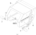
- Figure 1 shows an illustrative perspective view of a wire harness product clamping device and a safety cover 9 according to an exemplary embodiment of the present invention, wherein the wire harness product clamping device is in the use state and is moved to a first position
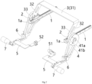
- Figure 2 shows an illustrative perspective view of a wire harness product clamping device according to an exemplary embodiment of the present invention, wherein the wire harness product clamping device is in the use state and moved to a first position
- Figure 3 shows an illustrative view of clamping wire harness product 8 onto the wire harness product clamping device shown in Figure 1
- Figure 4 shows an illustrative view of the wire harness product clamping device moved from the first position shown in Figure 3 to the second position, wherein the heat shrink tube 83 on the clamped wire harness product 8 is moved to the interior of the safety cover 9
- Figure 5 shows an illustrative perspective view of a wire harness product clamping device according to an exemplary embodiment of the present invention, wherein the wire harness product clamping device is in the use state and moved
- a wire harness product clamping device includes a pair of cantilevers 4 and various different wire harness fixtures 6, 51, and 52.
- the pair of cantilevers 4 are installed on the safety cover 9 of the heat shrink machine, can be moved between a first position and a second position and can be rotated between a use state and a storage state.
- Multiple different wire harness fixtures 6, 51, and 52 are installed on the cantilevers 4 to respectively clamp various wire harness products 8.
- the wiring harness product 8 typically includes a wiring harness 80 and a heat shrink tube 83 fitted onto the wiring harness 80.
- One of two ends 81 and 82 of the wire harness product 8 can be a wire harness extending from the heat shrink tube 83, a terminal pressed onto a single head wire harness, or the end of the heat shrink tube 83 fitted onto a single head wire harness.
- Figure 6 shows an illustrative perspective view of a wire harness product clamping device and a safety cover according to an exemplary embodiment of the present invention, wherein the wire harness product clamping device is in a storage state and is moved to a second position.
- the pair of cantilevers 4 are rotated from the use state to the storage state and moved from the first position to the second position. In this way, it won't take up production space, which is very convenient.
- the wire harness fixtures 6, 51, and 52 include a pair of first wire harness fixtures 6, which are respectively installed on the pair of cantilevers 4, suitable for respectively clamping two ends of a first wire harness product (not shown).
- the wire harness fixtures 6, 51, and 52 further include a pair of brackets 5 and a pair of second wire harness fixtures 51 and 52.
- the pair of brackets 5 are installed onto the pair of cantilevers 4.
- the pair of second wire harness fixtures 51 and 52 are respectively installed on the pair of brackets 5, suitable for clamping two ends 81 and 82 of a second wire harness product 8.
- the two ends 81 and 82 of the second wiring harness product 8 are different from each other.
- the pair of second wire harness fixtures 51 and 52 are different from each other and suitable for respectively clamping the two ends 81 and 82 of the second wire harness product 8.
- the bracket 5 is detachably installed on the cantilever 4 or the second wire harness fixtures 51 and 52 are detachably installed on the brackets 5, allowing for quick replacement of the second wire harness fixtures 51 and 52. In this way, different wire harness fixtures can be quickly replaced to clamp different wire harness products.
- the pair of cantilevers 4 are respectively installed on the outer sides of a pair of side walls 91 of the safety cover 9.
- the pair of first wire harness fixtures 6 are respectively located on the outside of the pair of side walls 91 of the safety cover 9, and the pair of second wire harness fixtures 51 and 52 are located inside the safety cover 9.
- the wire harness product clamping device further comprises a pair of sliding rails 1 and a pair of sliders 2.
- the pair of sliding rails 1 are suitable for being respectively fixed to the outer sides of the pair of side walls 91 of the safety cover 9.
- the pair of sliders 2 are slidably installed onto the pair of sliding rails 1 to be able to move along the pair of sliding rails 1.
- One ends of the pair of cantilevers 4 are respectively connected to the pair of sliders 2 to be able to move together with the pair of sliders 2.
- the wire harness product clamping device further includes a bridging member 3, which is bridged between the pair of sliders 2 to ensure synchronous movement of the pair of sliders 2 and the pair of cantilever arms 4.
- the bridging member 3 comprises a pair of arms 32, a crossbeam 31, and a pair of mounting seats 33.
- the crossbeam 31 is connected between one ends of the pair of arms 32.
- the pair of mounting seats 33 are respectively fixed to the other ends of the pair of arms 32.
- the pair of sliders 2 are respectively fixed to the inner sides facing each other of the pair of mounting seats 33, and one ends of the pair of cantilevers 4 are respectively connected to the outer sides of the pair of mounting seats 33.
- one ends of the pair of cantilevers 4 are rotatably connected to the pair of mounting seats 33, allowing the pair of cantilevers 4 to be rotated between the use state and the storage state.
- a pin hole 41a is formed in one end of the cantilever 4 and the mounting seat 33, and the wire harness product clamping device further includes a locking pin 41b suitable for matching with the pin hole 41a.
- the locking pin 41b is inserted into the pin hole 41a to lock the pair of cantilevers 4 at the use state or the storage state.
- the locking pin 41b needs to be pulled out of the pin hole 41a.
- the wire harness product clamping device further includes a pair of handles 7, which are respectively fixed to the other ends of the pair of cantilevers 4, so that the pair of handles 7 can drive the pair of cantilevers 4 to move between the first and second positions and rotate between the use and storage states.
- the sliding rail 1 extends along a first horizontal direction
- the rotation axes of the pair of cantilevers 4 extend along a second horizontal direction perpendicular to the first horizontal direction.
- a limiting block 1a is provided at the end of sliding rail 1, which is suitable for pressing against slider 2 or mounting seat 33 to limit the pair of cantilevers 4 at the first or second position.
- the brackets 5 on the pair of cantilevers 4 are in a position that does not interfere with the safety cover 9 to allow the pair of cantilevers 4 to rotate between the use state and the storage state.
- the brackets 5 on the pair of cantilevers 4 are in a position that interferes with the safety cover 9, preventing the pair of cantilevers 4 from being rotated between the use and storage states. Therefore, in the present invention, when it is necessary to rotate the pair of cantilevers 4, the pair of cantilevers 4 must first be moved to the first position.
- the pair of cantilevers 4 when the wire harness product clamping device is not required to use, the pair of cantilevers 4 are rotated from the use state to the storage state and moved from the first position to the second position. When the wire harness product clamping device is needed to use, the pair of cantilevers 4 are moved from the second position to the first position and rotated from the storage state to the use state.
- a heat shrink machine is also disclosed.
- the heat shrink machine includes: a safety cover 9, a heating device (not shown), and the aforementioned wire harness product clamping device.
- the wire harness product clamping device is used to clamp the wire harness product 8 and move the heat shrink tube 83 on the clamped wire harness product 8 to the inside of the safety cover 9.
- the heating device is used to heat the heat shrink tube 83 that has been moved inside the safety cover 9.
- wire harness fixtures 6, 51, and 52 are located below the bottom opening of the safety cover 9 to allow the heat shrink tubing 83 to enter the bottom opening of the safety cover 9.
- the wire harness fixtures 6, 51, and 52 are located above the top wall 90 of the safety cover 9, so as not to occupy production space.
- the integral external wire harness product clamping device of the present invention does not require additional space occupation, and can be quickly expanded for use and folded up for storage without disassembly, making it very convenient to use.
Landscapes
- Engineering & Computer Science (AREA)
- Manufacturing & Machinery (AREA)
- Installation Of Indoor Wiring (AREA)
- Insulated Conductors (AREA)
Abstract
The present invention discloses a wire harness product clamping device and a heat shrink machine. The wire harness product clamping device comprises of: a pair of cantilevers (4) installed on a heat shrink machine and capable of being moved between a first position and a second position and rotated between a use state and a storage state; and multiple different wire harness fixtures (6, 51, 52) installed on the cantilevers (4) to respectively clamp various different wire harness products (8). When the pair of cantilevers (4) are in the use state and moved to the first position, the wire harness fixtures (6, 51, 52) are located outside the heat shrink machine to facilitate clamping the wire harness products (8) by the wire harness fixtures (6, 51, 52); when the pair of cantilevers (4) are in the use state and moved from the first position to the second position, the heat shrink tube (83) on the wire harness product (8) clamped by the wire harness fixture (6, 51, 52) is moved from the outside of the heat shrink machine to the inside of the heat shrink machine. In the present invention, the structure of the wire harness product clamping device is simple and compact, capable of clamping different wire harness products, and can be quickly expanded for use and folded up for storage without occupying production space.
Description
- This application claims the benefit of Chinese Patent Application No.
CN202322153294.9 filed on August 10, 2023 - The present invention relates to a wire harness product clamping device for a heat shrink machine and a heat shrink machine comprising the wire harness product clamping device.
- In the prior art, a wire harness product includes a wire harness and a heat shrink tubing installed on the wire harness. In order to heat shrink the heat shrink tubing onto the wire harness, it is necessary to use a heat shrink machine to heat the heat shrink tubing installed on the wire harness. However, due to space limitations and limited applicability, the existing wire harness product clamping device built into the heat shrink machine can only hold an ordinary wire harness product and cannot hold other types of wire harness products, such as spliced wire harness products, wire harness products with crimped terminals, or wire harness products with multiple heat shrink tubes. Therefore, if you want to heat shrink other types of wire harness products, you can only rely on external wire harness product clamping devices. However, the existing external wire harness product clamping devices on the market take up a lot of space, making installation and disassembly inconvenient and inconvenient to use.
- The present invention has been made to overcome or alleviate at least one aspect of the above mentioned disadvantages.
- According to an aspect of the present invention, there is provided a wire harness product clamping device. The wire harness product clamping device comprises of: a pair of cantilevers installed on a heat shrink machine and capable of being moved between a first position and a second position and rotated between a use state and a storage state; and multiple different wire harness fixtures installed on the cantilevers to respectively clamp various different wire harness products. When the pair of cantilevers are in the use state and moved to the first position, the wire harness fixtures are located outside the heat shrink machine to facilitate clamping the wire harness products by the wire harness fixtures; when the pair of cantilevers are in the use state and moved from the first position to the second position, the heat shrink tube on the wire harness product clamped by the wire harness fixture is moved from the outside of the heat shrink machine to the inside of the heat shrink machine.
- According to an exemplary embodiment of the present invention, the pair of cantilevers are installed on a safety cover of the heat shrink machine; when the pair of cantilevers are in the use state and moved to the first position, the wire harness fixtures are located outside the safety cover; when the pair of cantilevers are in the use state and moved from the first position to the second position, the heat shrink tubing on the wire harness product clamped by the wire harness fixture is moved from the outside of the safety cover to the inside of the safety cover.
- According to another exemplary embodiment of the present invention, the wire harness fixtures include a pair of first wire harness fixtures which are respectively installed on the pair of cantilevers for respectively clamping two ends of a first wire harness product.
- According to another exemplary embodiment of the present invention, the wire harness fixtures further include: a pair of brackets which are respectively installed on the pair of cantilevers; and a pair of second wire harness fixtures which are respectively installed on the pair of brackets for respectively clamping two ends of a second wire harness product.
- According to another exemplary embodiment of the present invention, the two ends of the second wire harness product are different from each other, and the pair of second wire harness fixtures are different from each other and suitable for respectively clamping the two ends of the second wire harness product.
- According to another exemplary embodiment of the present invention, the bracket is detachably installed on the cantilever or the second wire harness fixture is detachably installed on the bracket, so that the second wire harness fixture can be quickly replaced.
- According to another exemplary embodiment of the present invention, the pair of cantilevers are respectively installed on outer sides of a pair of side walls of the safety cover; when the pair of cantilevers are in the use state and moved to the second position, the pair of first wire harness fixtures are respectively located on the outside of the pair of side walls of the safety cover, and the pair of second wire harness fixtures are located inside the safety cover.
- According to another exemplary embodiment of the present invention, the wire harness product clamping device further comprises of: a pair of sliding rails suitable for being respectively fixed to the outer sides of the pair of side walls of the safety cover; and a pair of sliders respectively slidably installed on the pair of sliding rails to be able to move along the pair of sliding rails. One ends of the pair of cantilevers are respectively connected to the pair of sliders to be able to move together with the pair of sliders.
- According to another exemplary embodiment of the present invention, the wire harness product clamping device further comprises a bridging member which is connected between the pair of sliders to ensure synchronous movement between the pair of sliders and the pair of cantilevers.
- According to another exemplary embodiment of the present invention, the bridging member comprises of: a pair of arms; a crossbeam connected between one ends of the pair of arms; and a pair of mounting seats respectively fixed to the other ends of the pair of arms. The pair of sliders are respectively fixed to the inner sides facing each other of the pair of mounting seats, and one ends of the pair of cantilevers are respectively connected to the outer side of the pair of mounting seats.
- According to another exemplary embodiment of the present invention, one ends of the pair of cantilevers are respectively rotatably connected to the pair of mounting seats, allowing the pair of cantilevers to be rotated between the use state and the storage state.
- According to another exemplary embodiment of the present invention, a pin hole is formed in one end of the cantilever and the mounting seat, and the wire harness product clamping device further includes a locking pin fitted in the pin hole; when the pair of cantilevers is in the use state or the storage state, the locking pin is inserted into the pin hole to lock the pair of cantilevers in the use state or the storage state.
- According to another exemplary embodiment of the present invention, the wire harness product clamping device further comprises a pair of handles which are respectively fixed to the other ends of the pair of cantilevers, so that the pair of cantilevers can be driven by the pair of handles to move between the first position and the second position, as well as to rotate between the use state and the storage state.
- According to another exemplary embodiment of the present invention, the sliding rail extends along a first horizontal direction, and the rotation axis of the pair of cantilevers extends along a second horizontal direction perpendicular to the first horizontal direction.
- According to another exemplary embodiment of the present invention, a limiting block is provided at the end of the sliding rail and is suitable for pressing against the slider or the mounting seat to limit the pair of cantilevers at the first position or the second position.
- According to another exemplary embodiment of the present invention, when the pair of cantilevers is moved to the first position, the bracket on the pair of cantilevers is in a position that does not interfere with the safety cover, so that the pair of cantilevers can be rotated between the use state and the storage state; when the pair of cantilevers is moved to the second position, the bracket on the pair of cantilevers is in a position that interferes with the safety cover, so that the pair of cantilevers cannot be rotated between the use state and the storage state.
- According to another exemplary embodiment of the present invention, when the wire harness product clamping device is not needed to use, the pair of cantilevers are rotated from the use state to the storage state and moved from the first position to the second position; when the wire harness product clamping device needs to be used, the pair of cantilevers are moved from the second position to the first position and rotated from the storage state to the use state.
- According to another aspect of the present invention, there is provided a heat shrink machine. The heat shrink machine comprises of: a safety cover; a heating device for heating a heat shrink tube that is moved inside the safety cover; and the above wire harness product clamping device, which is installed on the safety cover. The wire harness product clamping device is used to clamp the wire harness product and move the heat shrink tube on the clamped wire harness product to the inside of the safety cover.
- According to another exemplary embodiment of the present invention, when the pair of cantilevers are in the use state, the wire harness fixtures are located below the bottom opening of the safety cover; when the pair of cantilevers are in the storage state, the wire harness fixtures are located above the top wall of the safety cover.
- In the aforementioned exemplary embodiments of the present invention, the structure of the wire harness product clamping device is simple and compact, capable of clamping different wire harness products, and can be quickly expanded for use and folded up for storage without occupying production space.
- The above and other features of the present invention will become more apparent by describing in detail exemplary embodiments thereof with reference to the accompanying drawings, in which:
-
Figure 1 shows an illustrative perspective view of a wire harness product clamping device and a safety cover according to an exemplary embodiment of the present invention, wherein the wire harness product clamping device is in the use state and moved to a first position; -
Figure 2 shows an illustrative perspective view of a wire harness product clamping device according to an exemplary embodiment of the present invention, wherein the wire harness product clamping device is in the use state and moved to a first position; -
Figure 3 shows an illustrative view of clamping the wire harness product onto the wire harness product clamping device shown inFigure 1 ; -
Figure 4 shows an illustrative view of the wire harness product clamping device moved from the first position shown inFigure 3 to the second position, wherein the heat shrink tubing on the clamped wire harness product is moved to the interior of the safety cover; -
Figure 5 shows an illustrative perspective view of a wire harness product clamping device according to an exemplary embodiment of the present invention, wherein the wire harness product clamping device is in the use state and moved to a second position; and -
Figure 6 shows an illustrative perspective view of a wire harness product clamping device and a safety cover according to an exemplary embodiment of the present invention, wherein the wire harness product clamping device is in a storage state and is moved to a second position. - Exemplary embodiments of the present disclosure will be described hereinafter in detail with reference to the attached drawings, wherein the like reference numerals refer to the like elements. The present disclosure may, however, be embodied in many different forms and should not be construed as being limited to the embodiment set forth herein; rather, these embodiments are provided so that the present disclosure will be thorough and complete, and will fully convey the concept of the disclosure to those skilled in the art.
- In the following detailed description, for purposes of explanation, numerous specific details are set forth in order to provide a thorough understanding of the disclosed embodiments. It will be apparent, however, that one or more embodiments may be practiced without these specific details. In other instances, well-known structures and devices are schematically shown in order to simplify the drawing.
- According to a general concept of the present invention, there is provided a wire harness product clamping device. The wire harness product clamping device comprises of: a pair of cantilevers installed on a heat shrink machine and capable of being moved between a first position and a second position and rotated between a use state and a storage state; and multiple different wire harness fixtures installed on the cantilevers to respectively clamp various different wire harness products. When the pair of cantilevers are in the use state and moved to the first position, the wire harness fixtures are located outside the heat shrink machine to facilitate clamping the wire harness products by the wire harness fixtures; when the pair of cantilevers are in the use state and moved from the first position to the second position, the heat shrink tube on the wire harness product clamped by the wire harness fixture is moved from the outside of the heat shrink machine to the inside of the heat shrink machine.
- According to another general concept of the present invention, there is provided a heat shrink machine. The heat shrink machine comprises of: a safety cover; a heating device for heating a heat shrink tube that is moved inside the safety cover; and the above wire harness product clamping device, which is installed on the safety cover. The wire harness product clamping device is used to clamp the wire harness product and move the heat shrink tube on the clamped wire harness product to the inside of the safety cover.
-
Figure 1 shows an illustrative perspective view of a wire harness product clamping device and asafety cover 9 according to an exemplary embodiment of the present invention, wherein the wire harness product clamping device is in the use state and is moved to a first position;Figure 2 shows an illustrative perspective view of a wire harness product clamping device according to an exemplary embodiment of the present invention, wherein the wire harness product clamping device is in the use state and moved to a first position;Figure 3 shows an illustrative view of clampingwire harness product 8 onto the wire harness product clamping device shown inFigure 1 ;Figure 4 shows an illustrative view of the wire harness product clamping device moved from the first position shown inFigure 3 to the second position, wherein theheat shrink tube 83 on the clampedwire harness product 8 is moved to the interior of thesafety cover 9;Figure 5 shows an illustrative perspective view of a wire harness product clamping device according to an exemplary embodiment of the present invention, wherein the wire harness product clamping device is in the use state and moved to a second position. - As shown in
Figures 1 to 5 , in an exemplary embodiment of the present invention, a wire harness product clamping device is disclosed. The wire harness product clamping device includes a pair ofcantilevers 4 and various differentwire harness fixtures cantilevers 4 are installed on thesafety cover 9 of the heat shrink machine, can be moved between a first position and a second position and can be rotated between a use state and a storage state. Multiple differentwire harness fixtures cantilevers 4 to respectively clamp variouswire harness products 8. In the illustrated embodiment, thewiring harness product 8 typically includes awiring harness 80 and aheat shrink tube 83 fitted onto thewiring harness 80. One of two ends 81 and 82 of thewire harness product 8 can be a wire harness extending from the heat shrinktube 83, a terminal pressed onto a single head wire harness, or the end of the heat shrinktube 83 fitted onto a single head wire harness. - As shown in
Figures 1 to 5 , in the illustrated embodiments, when the pair ofcantilevers 4 are in the use state and moved to the first position (as shown inFigures 1-3 ), thewire harness fixtures safety cover 9 to facilitate clamping thewire harness product 8 onto thewire harness fixtures - As shown in
Figures 1 to 5 , in the illustrated embodiments, when the pair ofcantilevers 4 are in the use state and moved from the first position to the second position, the heat shrinktube 83 on thewire harness product 8 clamped bywire harness fixtures safety cover 9 to the inside of thesafety cover 9 to heat the heat shrinktube 83. -
Figure 6 shows an illustrative perspective view of a wire harness product clamping device and a safety cover according to an exemplary embodiment of the present invention, wherein the wire harness product clamping device is in a storage state and is moved to a second position. - As shown in
Figure 6 , in the illustrated embodiment, when the wire harness product clamping device is not needed to use, the pair ofcantilevers 4 are rotated from the use state to the storage state and moved from the first position to the second position. In this way, it won't take up production space, which is very convenient. - As shown in
Figures 1 to 6 , in the illustrated embodiments, thewire harness fixtures wire harness fixtures 6, which are respectively installed on the pair ofcantilevers 4, suitable for respectively clamping two ends of a first wire harness product (not shown). - As shown in
Figures 1 to 6 , in the illustrated embodiments, thewire harness fixtures brackets 5 and a pair of secondwire harness fixtures brackets 5 are installed onto the pair ofcantilevers 4. The pair of secondwire harness fixtures brackets 5, suitable for clamping two ends 81 and 82 of a secondwire harness product 8. - As shown in
Figures 1 to 6 , in the illustrated embodiment, the two ends 81 and 82 of the secondwiring harness product 8 are different from each other. The pair of secondwire harness fixtures wire harness product 8. - As shown in
Figures 1 to 6 , in the illustrated embodiments, thebracket 5 is detachably installed on thecantilever 4 or the secondwire harness fixtures brackets 5, allowing for quick replacement of the secondwire harness fixtures - As shown in
Figures 1 to 6 , in the illustrated embodiments, the pair ofcantilevers 4 are respectively installed on the outer sides of a pair ofside walls 91 of thesafety cover 9. When the pair ofcantilevers 4 are in the use state and moved to the second position, the pair of firstwire harness fixtures 6 are respectively located on the outside of the pair ofside walls 91 of thesafety cover 9, and the pair of secondwire harness fixtures safety cover 9. - As shown in
Figures 1 to 6 , in the illustrated embodiments, the wire harness product clamping device further comprises a pair of slidingrails 1 and a pair ofsliders 2. The pair of slidingrails 1 are suitable for being respectively fixed to the outer sides of the pair ofside walls 91 of thesafety cover 9. The pair ofsliders 2 are slidably installed onto the pair of slidingrails 1 to be able to move along the pair of slidingrails 1. One ends of the pair ofcantilevers 4 are respectively connected to the pair ofsliders 2 to be able to move together with the pair ofsliders 2. - As shown in
Figures 1 to 6 , in the illustrated embodiments, the wire harness product clamping device further includes a bridgingmember 3, which is bridged between the pair ofsliders 2 to ensure synchronous movement of the pair ofsliders 2 and the pair ofcantilever arms 4. - As shown in
Figures 1 to 6 , in the illustrated embodiments, the bridgingmember 3 comprises a pair ofarms 32, acrossbeam 31, and a pair of mountingseats 33. Thecrossbeam 31 is connected between one ends of the pair ofarms 32. The pair of mountingseats 33 are respectively fixed to the other ends of the pair ofarms 32. The pair ofsliders 2 are respectively fixed to the inner sides facing each other of the pair of mountingseats 33, and one ends of the pair ofcantilevers 4 are respectively connected to the outer sides of the pair of mountingseats 33. - As shown in
Figures 1 to 6 , in the illustrated embodiments, one ends of the pair ofcantilevers 4 are rotatably connected to the pair of mountingseats 33, allowing the pair ofcantilevers 4 to be rotated between the use state and the storage state. - As shown in
Figures 1 to 6 , in the illustrated embodiments, apin hole 41a is formed in one end of thecantilever 4 and the mountingseat 33, and the wire harness product clamping device further includes alocking pin 41b suitable for matching with thepin hole 41a. When the pair ofcantilevers 4 is in the use state or storage state, the lockingpin 41b is inserted into thepin hole 41a to lock the pair ofcantilevers 4 at the use state or the storage state. When it is necessary to rotate the pair ofcantilevers 4, the lockingpin 41b needs to be pulled out of thepin hole 41a. - As shown in
Figures 1 to 6 , in the illustrated embodiments, the wire harness product clamping device further includes a pair ofhandles 7, which are respectively fixed to the other ends of the pair ofcantilevers 4, so that the pair ofhandles 7 can drive the pair ofcantilevers 4 to move between the first and second positions and rotate between the use and storage states. - As shown in
Figures 1 to 6 , in the illustrated embodiments, the slidingrail 1 extends along a first horizontal direction, and the rotation axes of the pair ofcantilevers 4 extend along a second horizontal direction perpendicular to the first horizontal direction. - As shown in
Figures 1 to 6 , in the illustrated embodiments, a limitingblock 1a is provided at the end of slidingrail 1, which is suitable for pressing againstslider 2 or mountingseat 33 to limit the pair ofcantilevers 4 at the first or second position. - As shown in
Figures 1 to 6 , in the illustrated embodiments, when the pair ofcantilevers 4 is moved to the first position, thebrackets 5 on the pair ofcantilevers 4 are in a position that does not interfere with thesafety cover 9 to allow the pair ofcantilevers 4 to rotate between the use state and the storage state. When the pair ofcantilevers 4 is moved to the second position, thebrackets 5 on the pair ofcantilevers 4 are in a position that interferes with thesafety cover 9, preventing the pair ofcantilevers 4 from being rotated between the use and storage states. Therefore, in the present invention, when it is necessary to rotate the pair ofcantilevers 4, the pair ofcantilevers 4 must first be moved to the first position. - As shown in
Figures 1 to 6 , in the illustrated embodiments, when the wire harness product clamping device is not required to use, the pair ofcantilevers 4 are rotated from the use state to the storage state and moved from the first position to the second position. When the wire harness product clamping device is needed to use, the pair ofcantilevers 4 are moved from the second position to the first position and rotated from the storage state to the use state. - As shown in
Figures 1 to 6 , in another exemplary embodiment of the present invention, a heat shrink machine is also disclosed. The heat shrink machine includes: asafety cover 9, a heating device (not shown), and the aforementioned wire harness product clamping device. The wire harness product clamping device is used to clamp thewire harness product 8 and move the heat shrinktube 83 on the clampedwire harness product 8 to the inside of thesafety cover 9. The heating device is used to heat the heat shrinktube 83 that has been moved inside thesafety cover 9. - As shown in
Figures 1 to 6 , in the illustrated embodiments, when the pair ofcantilevers 4 are in the use state,wire harness fixtures safety cover 9 to allow the heat shrinktubing 83 to enter the bottom opening of thesafety cover 9. When the pair ofcantilevers 4 are in the storage state, thewire harness fixtures top wall 90 of thesafety cover 9, so as not to occupy production space. - As shown in
Figures 1 to 6 , the integral external wire harness product clamping device of the present invention does not require additional space occupation, and can be quickly expanded for use and folded up for storage without disassembly, making it very convenient to use. - It should be appreciated for those skilled in this art that the above embodiments are intended to be illustrated, and not restrictive. For example, many modifications may be made to the above embodiments by those skilled in this art, and various features described in different embodiments may be freely combined with each other without conflicting in configuration or principle.
- Although several exemplary embodiments have been shown and described, it would be appreciated by those skilled in the art that various changes or modifications may be made in these embodiments without departing from the principles and spirit of the disclosure, the scope of which is defined in the claims and their equivalents.
- As used herein, an element recited in the singular and proceeded with the word "a" or "an" should be understood as not excluding plural of said elements or steps, unless such exclusion is explicitly stated. Furthermore, references to "one embodiment" of the present invention are not intended to be interpreted as excluding the existence of additional embodiments that also incorporate the recited features. Moreover, unless explicitly stated to the contrary, embodiments "comprising" or "having" an element or a plurality of elements having a particular property may include additional such elements not having that property.
Claims (15)
- A wire harness product clamping device, comprising:a pair of cantilevers (4) installed on a heat shrink machine and capable of being moved between a first position and a second position and rotated between a use state and a storage state; andmultiple different wire harness fixtures (6, 51, 52) installed on the cantilevers (4) to respectively clamp various different wire harness products (8),wherein when the pair of cantilevers (4) are in the use state and moved to the first position, the wire harness fixtures (6, 51, 52) are located outside the heat shrink machine to facilitate clamping the wire harness products (8) by the wire harness fixtures (6, 51, 52);wherein when the pair of cantilevers (4) are in the use state and moved from the first position to the second position, the heat shrink tube (83) on the wire harness product (8) clamped by the wire harness fixture (6, 51, 52) is moved from the outside of the heat shrink machine to the inside of the heat shrink machine.
- The wire harness product clamping device according to claim 1,wherein the pair of cantilevers (4) are installed on a safety cover (9) of the heat shrink machine;wherein when the pair of cantilevers (4) are in the use state and moved to the first position, the wire harness fixtures (6, 51, 52) are located outside the safety cover (9);wherein when the pair of cantilevers (4) are in the use state and moved from the first position to the second position, the heat shrink tubing (83) on the wire harness product (8) clamped by the wire harness fixture (6, 51, 52) is moved from the outside of the safety cover (9) to the inside of the safety cover (9).
- The wire harness product clamping device according to claim 1 or 2,
wherein the wire harness fixtures (6, 51, 52) include:
a pair of first wire harness fixtures (6) which are respectively installed on the pair of cantilevers (4) for respectively clamping two ends of a first wire harness product. - The wire harness product clamping device according to claim 3,
wherein the wire harness fixtures (6, 51, 52) further include:a pair of brackets (5) which are respectively installed on the pair of cantilevers (4); anda pair of second wire harness fixtures (51, 52) which are respectively installed on the pair of brackets (5) for respectively clamping two ends (81, 82) of a second wire harness product (8). - The wire harness product clamping device according to claim 4,
wherein the two ends (81, 82) of the second wire harness product (8) are different from each other, and the pair of second wire harness fixtures (51, 52) are different from each other and suitable for respectively clamping the two ends (81, 82) of the second wire harness product (8). - The wire harness product clamping device according to claim 4 or 5,
wherein the bracket (5) is detachably installed on the cantilever (4) or the second wire harness fixture (51, 52) is detachably installed on the bracket (5), so that the second wire harness fixture (51, 52) can be quickly replaced. - The wire harness product clamping device according to claim 4, 5, or 6,wherein the pair of cantilevers (4) are respectively installed on outer sides of a pair of side walls (91) of the safety cover (9);wherein when the pair of cantilevers (4) are in the use state and moved to the second position, the pair of first wire harness fixtures (6) are respectively located on the outside of the pair of side walls (91) of the safety cover (9), and the pair of second wire harness fixtures (51, 52) are located inside the safety cover (9).
- The wire harness product clamping device according to claim 7, further comprising:a pair of sliding rails (1) suitable for being respectively fixed to the outer sides of the pair of side walls (91) of the safety cover (9); anda pair of sliders (2) respectively slidably installed on the pair of sliding rails (1) to be able to move along the pair of sliding rails (1),wherein one ends of the pair of cantilevers (4) are respectively connected to the pair of sliders (2) to be able to move together with the pair of sliders (2).
- The wire harness product clamping device according to claim 8, further comprising:a bridging member (3) which is connected between the pair of sliders (2) to ensure synchronous movement between the pair of sliders (2) and the pair of cantilevers (4),wherein the bridging member (3) comprises of:a pair of arms (32);a crossbeam (31) connected between one ends of the pair of arms (32); anda pair of mounting seats (33) respectively fixed to the other ends of the pair of arms (32),wherein the pair of sliders (2) are respectively fixed to the inner sides facing each other of the pair of mounting seats (33), and one ends of the pair of cantilevers (4) are respectively connected to the outer side of the pair of mounting seats (33); wherein optionallyone ends of the pair of cantilevers (4) are respectively rotatably connected to the pair of mounting seats (33), allowing the pair of cantilevers (4) to be rotated between the use state and the storage state,wherein a pin hole (41a) is formed in one end of the cantilever (4) and the mounting seat (33), and the wire harness product clamping device further includes a locking pin (41b) fitted in the pin hole (41a);wherein when the pair of cantilevers (4) is in the use state or the storage state, the locking pin (41b) is inserted into the pin hole (41a) to lock the pair of cantilevers (4) in the use state or the storage state.
- The wire harness product clamping device according to claim 9, further comprising:
a pair of handles (7) which are respectively fixed to the other ends of the pair of cantilevers (4), so that the pair of cantilevers (4) can be driven by the pair of handles (7) to move between the first position and the second position, as well as to rotate between the use state and the storage state. - The wire harness product clamping device according to claim 8, 9, or 10,
wherein the sliding rail (1) extends along a first horizontal direction, and the rotation axis of the pair of cantilevers (4) extends along a second horizontal direction perpendicular to the first horizontal direction. - The wire harness product clamping device according to claim 9, 10, or 11,
wherein a limiting block (1a) is provided at the end of the sliding rail (1) and is suitable for pressing against the slider (2) or the mounting seat (33) to limit the pair of cantilevers (4) at the first position or the second position. - The wire harness product clamping device according to any one of claims 4-12,wherein when the pair of cantilevers (4) is moved to the first position, the bracket (5) on the pair of cantilevers (4) is in a position that does not interfere with the safety cover (9), so that the pair of cantilevers (4) can be rotated between the use state and the storage state;wherein when the pair of cantilevers (4) is moved to the second position, the bracket (5) on the pair of cantilevers (4) is in a position that interferes with the safety cover (9), so that the pair of cantilevers (4) cannot be rotated between the use state and the storage state.
- The wire harness product clamping device according to any one of claims 1-13,wherein when the wire harness product clamping device is not needed to use, the pair of cantilevers (4) are rotated from the use state to the storage state and moved from the first position to the second position;wherein when the wire harness product clamping device needs to be used, the pair of cantilevers (4) are moved from the second position to the first position and rotated from the storage state to the use state.
- A heat shrink machine, comprising:a safety cover (9);a heating device for heating a heat shrink tube (83) that is moved inside the safety cover (9); andthe wire harness product clamping device according to any one of claims 1-14, which is installed on the safety cover (9),wherein the wire harness product clamping device is used to clamp the wire harness product (8) and move the heat shrink tube (83) on the clamped wire harness product (8) to the inside of the safety cover (9),wherein when the pair of cantilevers (4) are in the use state, the wire harness fixtures (6, 51, 52) are located below the bottom opening of the safety cover (9);wherein when the pair of cantilevers (4) are in the storage state, the wire harness fixtures (6, 51, 52) are located above the top wall (90) of the safety cover (9).
Applications Claiming Priority (1)
| Application Number | Priority Date | Filing Date | Title |
|---|---|---|---|
| CN202322153294.9U CN220280557U (en) | 2023-08-10 | 2023-08-10 | Wire harness product clamping device and thermal shrinkage machine |
Publications (1)
| Publication Number | Publication Date |
|---|---|
| EP4507139A1 true EP4507139A1 (en) | 2025-02-12 |
Family
ID=89335355
Family Applications (1)
| Application Number | Title | Priority Date | Filing Date |
|---|---|---|---|
| EP24193313.4A Pending EP4507139A1 (en) | 2023-08-10 | 2024-08-07 | Wire harness product clamping device and heat shrink machine |
Country Status (5)
| Country | Link |
|---|---|
| US (1) | US20250054659A1 (en) |
| EP (1) | EP4507139A1 (en) |
| JP (1) | JP2025026393A (en) |
| CN (1) | CN220280557U (en) |
| TW (1) | TW202506391A (en) |
Citations (3)
| Publication number | Priority date | Publication date | Assignee | Title |
|---|---|---|---|---|
| JP2004080932A (en) * | 2002-08-20 | 2004-03-11 | Yazaki Corp | Tube heating device and method of sealing electric wire connection |
| US20160004012A1 (en) * | 2007-01-31 | 2016-01-07 | Furukawa Electric Co., Ltd. | Ferrule transfer method and ferrule holder |
| CN113948942A (en) * | 2021-11-08 | 2022-01-18 | 广东科世得润汽车部件有限公司 | A throughput heat shrinking machine |
-
2023
- 2023-08-10 CN CN202322153294.9U patent/CN220280557U/en active Active
-
2024
- 2024-08-07 JP JP2024130513A patent/JP2025026393A/en active Pending
- 2024-08-07 TW TW113129504A patent/TW202506391A/en unknown
- 2024-08-07 US US18/796,900 patent/US20250054659A1/en active Pending
- 2024-08-07 EP EP24193313.4A patent/EP4507139A1/en active Pending
Patent Citations (3)
| Publication number | Priority date | Publication date | Assignee | Title |
|---|---|---|---|---|
| JP2004080932A (en) * | 2002-08-20 | 2004-03-11 | Yazaki Corp | Tube heating device and method of sealing electric wire connection |
| US20160004012A1 (en) * | 2007-01-31 | 2016-01-07 | Furukawa Electric Co., Ltd. | Ferrule transfer method and ferrule holder |
| CN113948942A (en) * | 2021-11-08 | 2022-01-18 | 广东科世得润汽车部件有限公司 | A throughput heat shrinking machine |
Also Published As
| Publication number | Publication date |
|---|---|
| JP2025026393A (en) | 2025-02-21 |
| CN220280557U (en) | 2024-01-02 |
| TW202506391A (en) | 2025-02-16 |
| US20250054659A1 (en) | 2025-02-13 |
Similar Documents
| Publication | Publication Date | Title |
|---|---|---|
| KR200480986Y1 (en) | An idler | |
| US8944474B2 (en) | Holder | |
| EP1653566A1 (en) | Axial latch actuator with locking wedge | |
| EP1860749B1 (en) | Support coil comprising a mechanical locking means and method for the production thereof | |
| KR20100041790A (en) | Electric power supply device for slide door | |
| US6659792B2 (en) | Electric connection box | |
| CN107112852A (en) | Linear actuator system | |
| CN101523064A (en) | Cable connection structure | |
| CN109417280B (en) | Leading end of cable guide, and wire harness | |
| CN1619091B (en) | Vehicle roller blind with simplified coupling mechanism of guide rails | |
| US20250054659A1 (en) | Wire Harness Product Clamping Device and Heat Shrink Machine | |
| CN111332963A (en) | Telescopic boom for crane and crane comprising telescopic boom | |
| EP4040604A1 (en) | Systems and methods for a cable connector | |
| US20250167464A1 (en) | Systems and methods for a cable connector | |
| CN106163200B (en) | Sliding rail assembly | |
| JP2003142208A (en) | Connector | |
| ES2323447T3 (en) | PLUG CONNECTOR FOR FLAT RIBBON CABLES. | |
| CN107910712B (en) | Plug | |
| ITTV20110139A1 (en) | TUBULAR GEAR MOTOR WITH FIXING SUPPORT | |
| JP2019503574A (en) | Electrical plug-in connection device | |
| CN217469361U (en) | Power cable protection pipe with clamping positioning structure | |
| JP3133276U (en) | Cable hanger coupler | |
| CN222457996U (en) | An internal wiring type electric lifting column | |
| EP4270662B1 (en) | Systems and methods for a cable connector | |
| JP2021103914A (en) | Electric connection box, electric connection box manufacturing device, electric connection box manufacturing method, and wire harness |
Legal Events
| Date | Code | Title | Description |
|---|---|---|---|
| PUAI | Public reference made under article 153(3) epc to a published international application that has entered the european phase |
Free format text: ORIGINAL CODE: 0009012 |
|
| STAA | Information on the status of an ep patent application or granted ep patent |
Free format text: STATUS: THE APPLICATION HAS BEEN PUBLISHED |
|
| AK | Designated contracting states |
Kind code of ref document: A1 Designated state(s): AL AT BE BG CH CY CZ DE DK EE ES FI FR GB GR HR HU IE IS IT LI LT LU LV MC ME MK MT NL NO PL PT RO RS SE SI SK SM TR |
|
| STAA | Information on the status of an ep patent application or granted ep patent |
Free format text: STATUS: REQUEST FOR EXAMINATION WAS MADE |
|
| 17P | Request for examination filed |
Effective date: 20250725 |