EP4507135A1 - Connector fixture and connector detection system - Google Patents
Connector fixture and connector detection system Download PDFInfo
- Publication number
- EP4507135A1 EP4507135A1 EP24193122.9A EP24193122A EP4507135A1 EP 4507135 A1 EP4507135 A1 EP 4507135A1 EP 24193122 A EP24193122 A EP 24193122A EP 4507135 A1 EP4507135 A1 EP 4507135A1
- Authority
- EP
- European Patent Office
- Prior art keywords
- connector
- rotating shaft
- transmission component
- camera
- clamping
- Prior art date
- Legal status (The legal status is an assumption and is not a legal conclusion. Google has not performed a legal analysis and makes no representation as to the accuracy of the status listed.)
- Granted
Links
Images




Classifications
-
- H—ELECTRICITY
- H01—ELECTRIC ELEMENTS
- H01R—ELECTRICALLY-CONDUCTIVE CONNECTIONS; STRUCTURAL ASSOCIATIONS OF A PLURALITY OF MUTUALLY-INSULATED ELECTRICAL CONNECTING ELEMENTS; COUPLING DEVICES; CURRENT COLLECTORS
- H01R43/00—Apparatus or processes specially adapted for manufacturing, assembling, maintaining, or repairing of line connectors or current collectors or for joining electric conductors
- H01R43/20—Apparatus or processes specially adapted for manufacturing, assembling, maintaining, or repairing of line connectors or current collectors or for joining electric conductors for assembling or disassembling contact members with insulating base, case or sleeve
-
- F—MECHANICAL ENGINEERING; LIGHTING; HEATING; WEAPONS; BLASTING
- F16—ENGINEERING ELEMENTS AND UNITS; GENERAL MEASURES FOR PRODUCING AND MAINTAINING EFFECTIVE FUNCTIONING OF MACHINES OR INSTALLATIONS; THERMAL INSULATION IN GENERAL
- F16M—FRAMES, CASINGS OR BEDS OF ENGINES, MACHINES OR APPARATUS, NOT SPECIFIC TO ENGINES, MACHINES OR APPARATUS PROVIDED FOR ELSEWHERE; STANDS; SUPPORTS
- F16M13/00—Other supports for positioning apparatus or articles; Means for steadying hand-held apparatus or articles
- F16M13/02—Other supports for positioning apparatus or articles; Means for steadying hand-held apparatus or articles for supporting on, or attaching to, an object, e.g. tree, gate, window-frame, cycle
- F16M13/022—Other supports for positioning apparatus or articles; Means for steadying hand-held apparatus or articles for supporting on, or attaching to, an object, e.g. tree, gate, window-frame, cycle repositionable
-
- B—PERFORMING OPERATIONS; TRANSPORTING
- B25—HAND TOOLS; PORTABLE POWER-DRIVEN TOOLS; MANIPULATORS
- B25B—TOOLS OR BENCH DEVICES NOT OTHERWISE PROVIDED FOR, FOR FASTENING, CONNECTING, DISENGAGING, OR HOLDING
- B25B11/00—Work holders not covered by any preceding group in the subclass, e.g. magnetic work holders, vacuum work holders
-
- B—PERFORMING OPERATIONS; TRANSPORTING
- B30—PRESSES
- B30B—PRESSES IN GENERAL
- B30B7/00—Presses characterised by a particular arrangement of the pressing members
- B30B7/04—Presses characterised by a particular arrangement of the pressing members wherein pressing is effected in different directions simultaneously or in turn
-
- G—PHYSICS
- G01—MEASURING; TESTING
- G01B—MEASURING LENGTH, THICKNESS OR SIMILAR LINEAR DIMENSIONS; MEASURING ANGLES; MEASURING AREAS; MEASURING IRREGULARITIES OF SURFACES OR CONTOURS
- G01B11/00—Measuring arrangements characterised by the use of optical techniques
- G01B11/22—Measuring arrangements characterised by the use of optical techniques for measuring depth
-
- G—PHYSICS
- G01—MEASURING; TESTING
- G01B—MEASURING LENGTH, THICKNESS OR SIMILAR LINEAR DIMENSIONS; MEASURING ANGLES; MEASURING AREAS; MEASURING IRREGULARITIES OF SURFACES OR CONTOURS
- G01B11/00—Measuring arrangements characterised by the use of optical techniques
- G01B11/26—Measuring arrangements characterised by the use of optical techniques for measuring angles or tapers; for testing the alignment of axes
-
- G—PHYSICS
- G06—COMPUTING OR CALCULATING; COUNTING
- G06T—IMAGE DATA PROCESSING OR GENERATION, IN GENERAL
- G06T7/00—Image analysis
- G06T7/0002—Inspection of images, e.g. flaw detection
-
- G—PHYSICS
- G06—COMPUTING OR CALCULATING; COUNTING
- G06T—IMAGE DATA PROCESSING OR GENERATION, IN GENERAL
- G06T7/00—Image analysis
- G06T7/50—Depth or shape recovery
- G06T7/55—Depth or shape recovery from multiple images
-
- G—PHYSICS
- G06—COMPUTING OR CALCULATING; COUNTING
- G06T—IMAGE DATA PROCESSING OR GENERATION, IN GENERAL
- G06T7/00—Image analysis
- G06T7/70—Determining position or orientation of objects or cameras
-
- G—PHYSICS
- G06—COMPUTING OR CALCULATING; COUNTING
- G06T—IMAGE DATA PROCESSING OR GENERATION, IN GENERAL
- G06T2207/00—Indexing scheme for image analysis or image enhancement
- G06T2207/30—Subject of image; Context of image processing
- G06T2207/30244—Camera pose
Definitions
- the present invention relates to a connector fixture and a connector detection system comprising the connector fixture.
- an observation window is usually formed on the connector housing, through which the camera can capture the terminals located inside the housing, and thus calculate the insertion depth of the terminals based on the captured terminal images.
- the present invention has been made to overcome or alleviate at least one aspect of the above mentioned disadvantages.
- a connector fixture comprising of: a fixed seat; a rotating shaft which passes through the fixed seat and is rotatably installed on the fixed seat; an installation block which is fixed to one end face of the rotating shaft and formed with multiple radial sliding slots spaced in a circumferential direction; multiple clamping claws which are respectively slidably installed in multiple radial sliding slots of the installation block; a transmission component which is sleeved on the rotating shaft and can be moved axially relative to the rotating shaft; and a driving member which is sleeved on the transmission component and is used to drive the transmission component to axially move.
- the transmission component has an installation hole, one end of the rotating shaft is inserted into the installation hole, and multiple grooves are formed on the inner wall surface of the installation hole, one ends of the multiple clamping jaws are respectively accommodated in the multiple grooves.
- a first inclined plane is formed on one end of the clamping claw, and a second inclined plane is formed on the inner side of the groove and is mated with the first inclined plane to convert an axial movement of the transmission component into a radial movement of multiple clamping claws to clamp a connector by the multiple clamping claws.
- the connector fixture comprises four clamping claws which are respectively slidably installed in the four radial sliding slots for radially clamping the connector.
- a central through-hole is formed in the rotating shaft and the installation block to allow the cable of the connector to pass through, the other ends of the multiple clamping jaws surround the central through-hole and are adjacent to each other, for radially clamping the cable of the connector.
- the transmission component can be moved between a first position and a second position along the axial direction of the rotating shaft under the drive of the driving member; when the transmission component is moved to the first position, the multiple clamping claws are driven to an opened position of releasing the cable; when the transmission component is moved to the second position, the multiple clamping jaws are driven to a clamping position for clamping the cable.
- the connector fixture further comprises an elastic element which is compressed between the clamping claw and the installation block to radially push the clamping claw towards the second inclined plane, so that the first inclined plane and the second inclined plane remain in contact with each other.
- a blind hole is formed in the installation block, one end of the elastic element is accommodated in the blind hole, the other end of the elastic element is pressed against one end of the clamping claw.
- the transmission component is rotationally connected to the driving member to allow the transmission component to rotate relative to the driving member.
- the transmission component comprises: a sleeve member which is fitted onto one end of the rotating shaft; a ring member connected to one end face of the sleeve member; and a washer member which is fitted onto one end of the sleeve member.
- a limiting flange is formed on the other end of the sleeve member, and the driving member is sleeved on the sleeve member and axially limited between the washer member and the limiting flange, and the sleeve member can be rotated relative to the driving member.
- the connector fixture further comprises a driver which is installed on the fixed seat and connected to the driving member, for driving the driving member to axially move and driving the transmission component to axially move through the driving member.
- the driver is a cylinder
- the cylinder body of the cylinder is fixed on the fixed seat
- the telescopic rod of the cylinder is connected to the driving member.
- the connector fixture further comprises a driving device which is installed on the fixed seat and connected to the other end of the rotating shaft, for driving the rotating shaft, the installation block, the clamping claws, and the transmission component to rotate synchronously.
- the driving device comprises of: a motor; and a transmission mechanism which is connected between the rotating shaft and the output shaft of the motor.
- the transmission mechanism is a gear transmission mechanism, and the gear transmission mechanism comprises of: a first gear fixed to the other end of the rotating shaft; and a second gear fixed to the output shaft of the motor, the first gear is meshed with the second gear.
- a connector detection system comprises: the above connector fixture for clamping a cable of a detected connector; a first camera for capturing an observation window on the housing of the detected connector; a second camera for capturing a terminal located inside the housing through the observation window; a calculation device for calculating an angle between the central axis of the observation window and the optical axis of the second camera based on the image of the observation window captured by the first camera; a control device for controlling the rotating shaft of the connector fixture to rotate the angle calculated by the calculation device, so that the observation window is rotated to an orientation directly facing the second camera.
- the second camera captures the terminal through the observation window.
- the calculation device further calculates an insertion depth of the terminal inserted into the housing based on the image captured by the second camera; when the difference between the calculated insertion depth of terminal and a predetermined insertion depth is greater than a predetermined value, the connector detection system determines that the insertion depth of terminal is unqualified; when the difference between the calculated insertion depth of terminal and the predetermined insertion depth is not greater than the predetermined value, the connector detection system determines that the insertion depth of terminal is qualified.
- the connector fixture can automatically clamp the connector and accurately rotate it to a predetermined orientation, improving the detection efficiency and quality of the connector.
- a connector fixture comprising of: a fixed seat; a rotating shaft which passes through the fixed seat and is rotatably installed on the fixed seat; an installation block which is fixed to one end face of the rotating shaft and formed with multiple radial sliding slots spaced in a circumferential direction; multiple clamping claws which are respectively slidably installed in multiple radial sliding slots of the installation block; a transmission component which is sleeved on the rotating shaft and can be moved axially relative to the rotating shaft; and a driving member which is sleeved on the transmission component and is used to drive the transmission component to axially move.
- the transmission component has an installation hole, one end of the rotating shaft is inserted into the installation hole, and multiple grooves are formed on the inner wall surface of the installation hole, one ends of the multiple clamping jaws are respectively accommodated in the multiple grooves.
- a first inclined plane is formed on one end of the clamping claw, and a second inclined plane is formed on the inner side of the groove and is mated with the first inclined plane to convert an axial movement of the transmission component into a radial movement of multiple clamping claws to clamp a connector by the multiple clamping claws.
- a connector detection system comprises: the above connector fixture for clamping a cable of a detected connector; a first camera for capturing an observation window on the housing of the detected connector; a second camera for capturing a terminal located inside the housing through the observation window; a calculation device for calculating an angle between the central axis of the observation window and the optical axis of the second camera based on the image of the observation window captured by the first camera; a control device for controlling the rotating shaft of the connector fixture to rotate the angle calculated by the calculation device, so that the observation window is rotated to an orientation directly facing the second camera.
- the second camera captures the terminal through the observation window.
- Figure 1 shows an illustrative perspective view of a connector fixture according to an exemplary embodiment of the present invention when viewed from one side
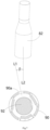
- Figure 2 shows an axial sectional view of a connector fixture according to an exemplary embodiment of the present invention
- Figure 3 shows an illustrative exploded view of a connector fixture according to an exemplary embodiment of the present invention
- Figure 4 shows an illustrative perspective view of a connector fixture according to an exemplary embodiment of the present invention when viewed from the other side
- Figure 5 shows an illustrative perspective view of a driving device according to an exemplary embodiment of the present invention.
- a connector fixture in an exemplary embodiment of the present invention, includes: a fixed seat 1, a rotating shaft 2, a transmission component 3, an installation block 4, multiple clamping jaws 5, and a driving member 62.
- the rotating shaft 2 passes through the fixed seat 1 and is rotatably installed to the fixed seat 1.
- the installation block 4 is fixed to the end face of one end of the rotating shaft 2 and formed with multiple radial sliding slots 41 that are spaced in a circumferential direction. Multiple clamping claws 5 are respectively slidably installed in multiple radial sliding slots 41 on installation block 4.
- the transmission component 3 is installed on the rotating shaft 2 and can be moved axially relative to the rotating shaft 2.
- the driving member 62 is installed on the transmission component 3 and is used to drive the transmission component 3 to axially move.
- the transmission component 3 has an installation hole 304, and one end of the rotating shaft 2 is inserted into the installation hole 304.
- Multiple grooves 305 are formed on the inner wall surface of the installation hole 304, and one ends 52 of the multiple clamping claws 5 are respectively accommodated in multiple grooves 305.
- a first inclined plane 52a is formed on one end 52 of the clamping claw 5, and a second inclined plane 32a is formed on the inner side of the groove 305.
- the second inclined plane 32a is mated with the first inclined plane 52a, in order to convert the axial movement of the transmission component 3 into the radial movement of multiple clamping claws 5 to clamp the connector 9 by the multiple clamping claws 5.
- the connector fixture comprises four clamping jaws 5, which are respectively slidably installed in four radial sliding slots 41 for radially clamping the connector 9.
- a central through-hole 201 is formed in the rotating shaft 2 and the installation block 4 that allows the cable 91 of the connector 9 to pass through.
- the other ends 51 of multiple clamping jaws 5 surround the central through-hole 201 and are adjacent to each other, used for radially clamping the cable 91 of the connector 9.
- the transmission component 3 can be moved between a first position and a second position along the axial direction of the rotating shaft 2 under the drive of the driving member 62.
- first position multiple clamping jaws 5 are driven to an opened position of releasing the cable 91.
- second position multiple clamping jaws 5 are driven to a clamping position of clamping the cable 91.
- the connector fixture further includes an elastic element 402, which is compressed between the clamping claw 5 and the installation block 4 to radially push the clamping claw 5 towards the second inclined plane 32a, so that the first inclined plane 52a and the second inclined plane 32a remain in contact with each other.
- the elastic element 402 can be a coil spring.
- an installation blind hole 401 is formed in the installation block 4, and one end of the elastic element 402 is accommodated in the installation blind hole 401, while the other end of the elastic element 402 is pressed against one end 52 of the clamping claw 5.
- the transmission component 3 is rotationally connected to the driving member 62 to allow the transmission component 3 to rotate relative to the driving member 62.
- the transmission component 3 comprises a sleeve member 31, a ring member 32, and a washer member 33.
- the sleeve member 31 is installed on one end of the rotating shaft 2.
- the ring member 32 is connected to the end face of one end of the sleeve member 31.
- the washer member 33 is fitted onto one end of the sleeve member 31.
- a limiting flange 31a is formed on the other end of the sleeve member 31, and the driving member 62 is sleeved on the sleeve member 31 and axially limited between the washer member 33 and the limiting flange 31a, and the sleeve member 31 can be rotated relative to the driving member 62.
- the connector fixture further comprises a driver, which is installed on the fixed seat 1 and connected to the driving member 62, for driving the driving member 62 to axially move and driving the transmission component 3 to axially move through the driving member 62.
- a driver which is installed on the fixed seat 1 and connected to the driving member 62, for driving the driving member 62 to axially move and driving the transmission component 3 to axially move through the driving member 62.
- the driver can be a cylinder 6, the cylinder body 60 of cylinder 6 is fixed on the fixed seat 1, and the telescopic rod 61 of cylinder 6 is connected to the driving member 62.
- the driver can also be a hydraulic cylinder or an electric cylinder.
- the connector fixture further comprises a driving device, which is installed on the fixed seat 1 and connected to the other end of the rotating shaft 2, for driving the rotating shaft 2, the installation block 4, the clamping claw 5, and the transmission component 3 to rotate synchronously.
- a driving device which is installed on the fixed seat 1 and connected to the other end of the rotating shaft 2, for driving the rotating shaft 2, the installation block 4, the clamping claw 5, and the transmission component 3 to rotate synchronously.
- the clamped connector 9 can be rotated to a predetermined orientation.
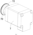
- the driving device comprises a motor 7 and a transmission mechanism.
- the transmission mechanism is connected between the output shaft 70 of the motor 7and the rotating shaft 2.
- the transmission mechanism is a gear transmission mechanism.
- the transmission mechanism includes a first gear 71 and a second gear 72.
- the first gear 71 is fixed to the other end of the rotating shaft 2.
- the second gear 72 is fixed to the output shaft 70 of motor 7.
- the first gear 71 is meshed with the second gear 72.
- Figure 6 shows an illustrative perspective view of the first camera 81, second camera 82, and connector 9 of a connector detection system according to an exemplary embodiment of the present invention
- Figure 7 shows an illustrative view of the second camera 82 and connector 9 of a connector detection system according to an exemplary embodiment of the present invention, where the observation window 90a on the connector is not facing the second camera 82
- Figure 8 shows an illustrative view of the second camera 82 and connector 9 of a connector detection system according to an exemplary embodiment of the present invention, wherein the observation window 90a on connector 9 is rotated to face the second camera 82.
- a connector detection system is also disclosed.
- the connector detection system includes: the aforementioned connector fixture, a first camera 81, a second camera 82, a calculation device (not shown), and a control device (not shown).
- the connector fixture is used to clamp the cable 91 of the detected connector 9.
- the first camera 81 is used to capture the observation window 90a on the housing 90 of the detected connector 9.
- the second camera 82 is used to capture the terminal 92 located inside the housing 90 through the observation window 90a.
- the calculation device calculates the angle ⁇ between the central axis L1 of the observation window 90a and the optical axis L2 of the second camera 82 based on the image of the observation window 90a captured by the first camera 81.
- the control device controls the rotating shaft 2 of the connector fixture to rotate the corresponding angle ⁇ calculated by the calculation device, so that the observation window 90a is rotated to an orientation facing the second camera 82.
- the second camera 82 captures the terminal 92 through the observation window 90a.
- the calculation device also calculates the insertion depth of the terminal 92 inserted into the housing 90 based on the image of the terminal 92 captured by the second camera 82.
- the connector detection system determines that the insertion depth of terminal 92 is unqualified.
- the connector detection system determines that the insertion depth of terminal 92 is qualified.
Landscapes
- Engineering & Computer Science (AREA)
- Physics & Mathematics (AREA)
- General Physics & Mathematics (AREA)
- Computer Vision & Pattern Recognition (AREA)
- Theoretical Computer Science (AREA)
- Mechanical Engineering (AREA)
- General Engineering & Computer Science (AREA)
- Quality & Reliability (AREA)
- Manufacturing & Machinery (AREA)
- Details Of Connecting Devices For Male And Female Coupling (AREA)
- Manufacturing Of Electrical Connectors (AREA)
Abstract
Description
- This application claims the benefit of Chinese Patent Application No.
CN202311001514.4 filed on August 9, 2023 - The present invention relates to a connector fixture and a connector detection system comprising the connector fixture.
- In the prior art, in order to detect the insertion depth of the connector terminals, an observation window is usually formed on the connector housing, through which the camera can capture the terminals located inside the housing, and thus calculate the insertion depth of the terminals based on the captured terminal images. To ensure that the connector remains stationary during shooting, it is necessary to clamp the connector onto the connector fixture and ensure that the observation window on the connector faces the camera.
- In the prior art, it is common to manually place and control the placement angle of the connector so that the observation window on the connector faces the camera. Due to the small size of the connector, it is often not possible to manually place the angle of the connector in place at once, resulting in the camera not being able to capture the terminals. Multiple attempts are needed to repeatedly adjust the placement angle of the connector, which seriously reduces detection efficiency and quality.
- The present invention has been made to overcome or alleviate at least one aspect of the above mentioned disadvantages.
- According to an aspect of the present invention, there is provided a connector fixture. The connector fixture comprises of: a fixed seat; a rotating shaft which passes through the fixed seat and is rotatably installed on the fixed seat; an installation block which is fixed to one end face of the rotating shaft and formed with multiple radial sliding slots spaced in a circumferential direction; multiple clamping claws which are respectively slidably installed in multiple radial sliding slots of the installation block; a transmission component which is sleeved on the rotating shaft and can be moved axially relative to the rotating shaft; and a driving member which is sleeved on the transmission component and is used to drive the transmission component to axially move. The transmission component has an installation hole, one end of the rotating shaft is inserted into the installation hole, and multiple grooves are formed on the inner wall surface of the installation hole, one ends of the multiple clamping jaws are respectively accommodated in the multiple grooves. A first inclined plane is formed on one end of the clamping claw, and a second inclined plane is formed on the inner side of the groove and is mated with the first inclined plane to convert an axial movement of the transmission component into a radial movement of multiple clamping claws to clamp a connector by the multiple clamping claws.
- According to another exemplary embodiment of the present invention, four radial sliding slots are formed on the installation block, and the four radial sliding slots are evenly spaced in the circumferential direction, so that the four radial sliding slots are in a cross shape; the connector fixture comprises four clamping claws which are respectively slidably installed in the four radial sliding slots for radially clamping the connector.
- According to another exemplary embodiment of the present invention, a central through-hole is formed in the rotating shaft and the installation block to allow the cable of the connector to pass through, the other ends of the multiple clamping jaws surround the central through-hole and are adjacent to each other, for radially clamping the cable of the connector.
- According to another exemplary embodiment of the present invention, the transmission component can be moved between a first position and a second position along the axial direction of the rotating shaft under the drive of the driving member; when the transmission component is moved to the first position, the multiple clamping claws are driven to an opened position of releasing the cable; when the transmission component is moved to the second position, the multiple clamping jaws are driven to a clamping position for clamping the cable.
- According to another exemplary embodiment of the present invention, the connector fixture further comprises an elastic element which is compressed between the clamping claw and the installation block to radially push the clamping claw towards the second inclined plane, so that the first inclined plane and the second inclined plane remain in contact with each other.
- According to another exemplary embodiment of the present invention, a blind hole is formed in the installation block, one end of the elastic element is accommodated in the blind hole, the other end of the elastic element is pressed against one end of the clamping claw.
- According to another exemplary embodiment of the present invention, the transmission component is rotationally connected to the driving member to allow the transmission component to rotate relative to the driving member.
- According to another exemplary embodiment of the present invention, the transmission component comprises: a sleeve member which is fitted onto one end of the rotating shaft; a ring member connected to one end face of the sleeve member; and a washer member which is fitted onto one end of the sleeve member. A limiting flange is formed on the other end of the sleeve member, and the driving member is sleeved on the sleeve member and axially limited between the washer member and the limiting flange, and the sleeve member can be rotated relative to the driving member.
- According to another exemplary embodiment of the present invention, the connector fixture further comprises a driver which is installed on the fixed seat and connected to the driving member, for driving the driving member to axially move and driving the transmission component to axially move through the driving member.
- According to another exemplary embodiment of the present invention, the driver is a cylinder, and the cylinder body of the cylinder is fixed on the fixed seat, the telescopic rod of the cylinder is connected to the driving member.
- According to another exemplary embodiment of the present invention, the connector fixture further comprises a driving device which is installed on the fixed seat and connected to the other end of the rotating shaft, for driving the rotating shaft, the installation block, the clamping claws, and the transmission component to rotate synchronously.
- According to another exemplary embodiment of the present invention, the driving device comprises of: a motor; and a transmission mechanism which is connected between the rotating shaft and the output shaft of the motor.
- According to another exemplary embodiment of the present invention, the transmission mechanism is a gear transmission mechanism, and the gear transmission mechanism comprises of: a first gear fixed to the other end of the rotating shaft; and a second gear fixed to the output shaft of the motor, the first gear is meshed with the second gear.
- According to another aspect of the present invention, there is provided a connector detection system. The connector detection system comprises: the above connector fixture for clamping a cable of a detected connector; a first camera for capturing an observation window on the housing of the detected connector; a second camera for capturing a terminal located inside the housing through the observation window; a calculation device for calculating an angle between the central axis of the observation window and the optical axis of the second camera based on the image of the observation window captured by the first camera; a control device for controlling the rotating shaft of the connector fixture to rotate the angle calculated by the calculation device, so that the observation window is rotated to an orientation directly facing the second camera. When the observation window on the housing of the connector is rotated to the orientation directly facing the second camera, the second camera captures the terminal through the observation window.
- According to an exemplary embodiment of the present invention, the calculation device further calculates an insertion depth of the terminal inserted into the housing based on the image captured by the second camera; when the difference between the calculated insertion depth of terminal and a predetermined insertion depth is greater than a predetermined value, the connector detection system determines that the insertion depth of terminal is unqualified; when the difference between the calculated insertion depth of terminal and the predetermined insertion depth is not greater than the predetermined value, the connector detection system determines that the insertion depth of terminal is qualified.
- In the aforementioned exemplary embodiments of the present invention, the connector fixture can automatically clamp the connector and accurately rotate it to a predetermined orientation, improving the detection efficiency and quality of the connector.
- The above and other features of the present invention will become more apparent by describing in detail exemplary embodiments thereof with reference to the accompanying drawings, in which:
-
Figure 1 shows an illustrative perspective view of a connector fixture according to an exemplary embodiment of the present invention when viewed from one side; -
Figure 2 shows an axial sectional view of a connector fixture according to an exemplary embodiment of the present invention; -
Figure 3 shows an illustrative exploded view of a connector fixture according to an exemplary embodiment of the present invention; -
Figure 4 shows an illustrative perspective view of a connector fixture according to an exemplary embodiment of the present invention when viewed from the other side; -
Figure 5 shows an illustrative perspective view of a driving device according to an exemplary embodiment of the present invention; -
Figure 6 shows an illustrative perspective view of the first camera, second camera, and connector of a connector detection system according to an exemplary embodiment of the present invention; -
Figure 7 shows an illustrative view of a second camera and connector of a connector detection system according to an exemplary embodiment of the present invention, wherein the observation window on the connector is not facing the second camera; and -
Figure 8 shows an illustrative view of a second camera and connector of a connector detection system according to an exemplary embodiment of the present invention, wherein the observation window on the connector is rotated to face the second camera. - Exemplary embodiments of the present disclosure will be described hereinafter in detail with reference to the attached drawings, wherein the like reference numerals refer to the like elements. The present disclosure may, however, be embodied in many different forms and should not be construed as being limited to the embodiment set forth herein; rather, these embodiments are provided so that the present disclosure will be thorough and complete, and will fully convey the concept of the disclosure to those skilled in the art.
- In the following detailed description, for purposes of explanation, numerous specific details are set forth in order to provide a thorough understanding of the disclosed embodiments. It will be apparent, however, that one or more embodiments may be practiced without these specific details. In other instances, well-known structures and devices are schematically shown in order to simplify the drawing.
- According to a general concept of the present invention, there is provided a connector fixture. The connector fixture comprises of: a fixed seat; a rotating shaft which passes through the fixed seat and is rotatably installed on the fixed seat; an installation block which is fixed to one end face of the rotating shaft and formed with multiple radial sliding slots spaced in a circumferential direction; multiple clamping claws which are respectively slidably installed in multiple radial sliding slots of the installation block; a transmission component which is sleeved on the rotating shaft and can be moved axially relative to the rotating shaft; and a driving member which is sleeved on the transmission component and is used to drive the transmission component to axially move. The transmission component has an installation hole, one end of the rotating shaft is inserted into the installation hole, and multiple grooves are formed on the inner wall surface of the installation hole, one ends of the multiple clamping jaws are respectively accommodated in the multiple grooves. A first inclined plane is formed on one end of the clamping claw, and a second inclined plane is formed on the inner side of the groove and is mated with the first inclined plane to convert an axial movement of the transmission component into a radial movement of multiple clamping claws to clamp a connector by the multiple clamping claws.
- According to another general concept of the present invention, there is provided a connector detection system. The connector detection system comprises: the above connector fixture for clamping a cable of a detected connector; a first camera for capturing an observation window on the housing of the detected connector; a second camera for capturing a terminal located inside the housing through the observation window; a calculation device for calculating an angle between the central axis of the observation window and the optical axis of the second camera based on the image of the observation window captured by the first camera; a control device for controlling the rotating shaft of the connector fixture to rotate the angle calculated by the calculation device, so that the observation window is rotated to an orientation directly facing the second camera. When the observation window on the housing of the connector is rotated to the orientation directly facing the second camera, the second camera captures the terminal through the observation window.
-
Figure 1 shows an illustrative perspective view of a connector fixture according to an exemplary embodiment of the present invention when viewed from one side;Figure 2 shows an axial sectional view of a connector fixture according to an exemplary embodiment of the present invention;Figure 3 shows an illustrative exploded view of a connector fixture according to an exemplary embodiment of the present invention;Figure 4 shows an illustrative perspective view of a connector fixture according to an exemplary embodiment of the present invention when viewed from the other side;Figure 5 shows an illustrative perspective view of a driving device according to an exemplary embodiment of the present invention. - As shown in
Figures 1 to 5 , in an exemplary embodiment of the present invention, a connector fixture is disclosed. The connector fixture includes: afixed seat 1, a rotatingshaft 2, atransmission component 3, aninstallation block 4,multiple clamping jaws 5, and adriving member 62. The rotatingshaft 2 passes through thefixed seat 1 and is rotatably installed to thefixed seat 1. Theinstallation block 4 is fixed to the end face of one end of the rotatingshaft 2 and formed with multipleradial sliding slots 41 that are spaced in a circumferential direction.Multiple clamping claws 5 are respectively slidably installed in multipleradial sliding slots 41 oninstallation block 4. Thetransmission component 3 is installed on therotating shaft 2 and can be moved axially relative to the rotatingshaft 2. The drivingmember 62 is installed on thetransmission component 3 and is used to drive thetransmission component 3 to axially move. Thetransmission component 3 has aninstallation hole 304, and one end of therotating shaft 2 is inserted into theinstallation hole 304.Multiple grooves 305 are formed on the inner wall surface of theinstallation hole 304, and one ends 52 of themultiple clamping claws 5 are respectively accommodated inmultiple grooves 305. A firstinclined plane 52a is formed on oneend 52 of the clampingclaw 5, and a secondinclined plane 32a is formed on the inner side of thegroove 305. The secondinclined plane 32a is mated with the firstinclined plane 52a, in order to convert the axial movement of thetransmission component 3 into the radial movement of multiple clampingclaws 5 to clamp theconnector 9 by the multiple clampingclaws 5. - As shown in
Figures 1 to 5 , in the illustrated embodiments, four radial slidingslots 41 are formed on theinstallation block 4, and the four radial slidingslots 41 are evenly spaced in the circumferential direction, so that the four radial slidingslots 41 form a cross shape. The connector fixture comprises four clampingjaws 5, which are respectively slidably installed in four radial slidingslots 41 for radially clamping theconnector 9. - As shown in
Figures 1 to 5 , in the illustrated embodiments, a central through-hole 201 is formed in therotating shaft 2 and theinstallation block 4 that allows thecable 91 of theconnector 9 to pass through. The other ends 51 of multiple clampingjaws 5 surround the central through-hole 201 and are adjacent to each other, used for radially clamping thecable 91 of theconnector 9. - As shown in
Figures 1 to 5 , in the illustrated embodiment, thetransmission component 3 can be moved between a first position and a second position along the axial direction of therotating shaft 2 under the drive of the drivingmember 62. When thetransmission component 3 is moved to the first position, multiple clampingjaws 5 are driven to an opened position of releasing thecable 91. When thetransmission component 3 is moved to the second position, multiple clampingjaws 5 are driven to a clamping position of clamping thecable 91. - As shown in
Figures 1 to 5 , in the illustrated embodiments, the connector fixture further includes anelastic element 402, which is compressed between the clampingclaw 5 and theinstallation block 4 to radially push theclamping claw 5 towards the secondinclined plane 32a, so that the firstinclined plane 52a and the secondinclined plane 32a remain in contact with each other. Theelastic element 402 can be a coil spring. - As shown in
Figures 1 to 5 , in the illustrated embodiments, aninstallation blind hole 401 is formed in theinstallation block 4, and one end of theelastic element 402 is accommodated in theinstallation blind hole 401, while the other end of theelastic element 402 is pressed against oneend 52 of the clampingclaw 5. - As shown in
Figures 1 to 5 , in the illustrated embodiments, thetransmission component 3 is rotationally connected to the drivingmember 62 to allow thetransmission component 3 to rotate relative to the drivingmember 62. - As shown in
Figures 1 to 5 , in the illustrated embodiments, thetransmission component 3 comprises asleeve member 31, aring member 32, and awasher member 33. Thesleeve member 31 is installed on one end of therotating shaft 2. Thering member 32 is connected to the end face of one end of thesleeve member 31. Thewasher member 33 is fitted onto one end of thesleeve member 31. A limitingflange 31a is formed on the other end of thesleeve member 31, and the drivingmember 62 is sleeved on thesleeve member 31 and axially limited between thewasher member 33 and the limitingflange 31a, and thesleeve member 31 can be rotated relative to the drivingmember 62. - As shown in
Figures 1 to 5 , in the illustrated embodiments, the connector fixture further comprises a driver, which is installed on the fixedseat 1 and connected to the drivingmember 62, for driving the drivingmember 62 to axially move and driving thetransmission component 3 to axially move through the drivingmember 62. - As shown in
Figures 1 to 5 , in the illustrated embodiments, the driver can be acylinder 6, thecylinder body 60 ofcylinder 6 is fixed on the fixedseat 1, and thetelescopic rod 61 ofcylinder 6 is connected to the drivingmember 62. However, the present invention is not limited to the illustrated embodiments, for example, the driver can also be a hydraulic cylinder or an electric cylinder. - As shown in
Figures 1 to 5 , in the illustrated embodiments, the connector fixture further comprises a driving device, which is installed on the fixedseat 1 and connected to the other end of therotating shaft 2, for driving therotating shaft 2, theinstallation block 4, the clampingclaw 5, and thetransmission component 3 to rotate synchronously. In this way, the clampedconnector 9 can be rotated to a predetermined orientation. - As shown in
Figures 1 to 5 , in the illustrated embodiments, the driving device comprises amotor 7 and a transmission mechanism. The transmission mechanism is connected between theoutput shaft 70 of the motor 7and therotating shaft 2. In the illustrated embodiment, the transmission mechanism is a gear transmission mechanism. The transmission mechanism includes afirst gear 71 and asecond gear 72. Thefirst gear 71 is fixed to the other end of therotating shaft 2. Thesecond gear 72 is fixed to theoutput shaft 70 ofmotor 7. Thefirst gear 71 is meshed with thesecond gear 72. -
Figure 6 shows an illustrative perspective view of thefirst camera 81,second camera 82, andconnector 9 of a connector detection system according to an exemplary embodiment of the present invention;Figure 7 shows an illustrative view of thesecond camera 82 andconnector 9 of a connector detection system according to an exemplary embodiment of the present invention, where theobservation window 90a on the connector is not facing thesecond camera 82;Figure 8 shows an illustrative view of thesecond camera 82 andconnector 9 of a connector detection system according to an exemplary embodiment of the present invention, wherein theobservation window 90a onconnector 9 is rotated to face thesecond camera 82. - As shown in
Figures 1 to 8 , in another exemplary embodiment of the present invention, a connector detection system is also disclosed. The connector detection system includes: the aforementioned connector fixture, afirst camera 81, asecond camera 82, a calculation device (not shown), and a control device (not shown). The connector fixture is used to clamp thecable 91 of the detectedconnector 9. Thefirst camera 81 is used to capture theobservation window 90a on thehousing 90 of the detectedconnector 9. Thesecond camera 82 is used to capture the terminal 92 located inside thehousing 90 through theobservation window 90a. The calculation device calculates the angle β between the central axis L1 of theobservation window 90a and the optical axis L2 of thesecond camera 82 based on the image of theobservation window 90a captured by thefirst camera 81. The control device controls therotating shaft 2 of the connector fixture to rotate the corresponding angle β calculated by the calculation device, so that theobservation window 90a is rotated to an orientation facing thesecond camera 82. When theobservation window 90a on thehousing 90 ofconnector 9 is rotated to the orientation facing thesecond camera 82, thesecond camera 82 captures the terminal 92 through theobservation window 90a. - As shown in
Figures 1 to 8 , in the illustrated embodiments, the calculation device also calculates the insertion depth of the terminal 92 inserted into thehousing 90 based on the image of the terminal 92 captured by thesecond camera 82. When the difference between the calculated insertion depth ofterminal 92 and a predetermined insertion depth is greater than a predetermined value, the connector detection system determines that the insertion depth ofterminal 92 is unqualified. When the difference between the calculated insertion depth ofterminal 92 and the predetermined insertion depth is not greater than the predetermined value, the connector detection system determines that the insertion depth ofterminal 92 is qualified. - It should be appreciated for those skilled in this art that the above embodiments are intended to be illustrated, and not restrictive. For example, many modifications may be made to the above embodiments by those skilled in this art, and various features described in different embodiments may be freely combined with each other without conflicting in configuration or principle.
- Although several exemplary embodiments have been shown and described, it would be appreciated by those skilled in the art that various changes or modifications may be made in these embodiments without departing from the principles and spirit of the disclosure, the scope of which is defined in the claims and their equivalents.
- As used herein, an element recited in the singular and proceeded with the word "a" or "an" should be understood as not excluding plural of said elements or steps, unless such exclusion is explicitly stated. Furthermore, references to "one embodiment" of the present invention are not intended to be interpreted as excluding the existence of additional embodiments that also incorporate the recited features. Moreover, unless explicitly stated to the contrary, embodiments "comprising" or "having" an element or a plurality of elements having a particular property may include additional such elements not having that property.
Claims (15)
- A connector fixture, comprises:a fixed seat (1);a rotating shaft (2) which passes through the fixed seat (1) and is rotatably installed on the fixed seat (1);an installation block (4) which is fixed to one end face of the rotating shaft (2) and formed with multiple radial sliding slots (41) spaced in a circumferential direction;multiple clamping claws (5) which are respectively slidably installed in multiple radial sliding slots (41) of the installation block (4);a transmission component (3) which is sleeved on the rotating shaft (2) and can be moved axially relative to the rotating shaft (2); anda driving member (62) which is sleeved on the transmission component (3) and is used to drive the transmission component (3) to axially move,wherein the transmission component (3) has an installation hole (304), one end of the rotating shaft (2) is inserted into the installation hole (304), and multiple grooves (305) are formed on the inner wall surface of the installation hole (304), one ends (52) of the multiple clamping jaws (5) are respectively accommodated in the multiple grooves (305),wherein a first inclined plane (52a) is formed on one end (52) of the clamping claw (5), and a second inclined plane (32a) is formed on the inner side of the groove (305) and is mated with the first inclined plane (52a) to convert an axial movement of the transmission component (3) into a radial movement of multiple clamping claws (5) to clamp a connector (9) by the multiple clamping claws (5).
- The connector fixture according to claim 1,wherein four radial sliding slots (41) are formed on the installation block (4), and the four radial sliding slots (41) are evenly spaced in the circumferential direction, so that the four radial sliding slots (41) are in a cross shape;wherein the connector fixture comprises four clamping claws (5) which are respectively slidably installed in the four radial sliding slots (41) for radially clamping the connector (9).
- The connector fixture according to claim 1,
wherein a central through-hole (201) is formed in the rotating shaft (2) and the installation block (4) to allow the cable (91) of the connector (9) to pass through, the other ends (51) of the multiple clamping jaws (5) surround the central through-hole (201) and are adjacent to each other, for radially clamping the cable (91) of the connector (9). - The connector fixture according to claim 3,wherein the transmission component (3) can be moved between a first position and a second position along the axial direction of the rotating shaft (2) under the drive of the driving member (62);wherein when the transmission component (3) is moved to the first position, the multiple clamping claws (5) are driven to an opened position of releasing the cable (91);wherein when the transmission component (3) is moved to the second position, the multiple clamping jaws (5) are driven to a clamping position for clamping the cable (91).
- The connector fixture according to claim 4, further comprising:
an elastic element (402) which is compressed between the clamping claw (5) and the installation block (4) to radially push the clamping claw (5) towards the second inclined plane (32a), so that the first inclined plane (52a) and the second inclined plane (32a) remain in contact with each other. - The connector fixture according to claim 5,
wherein a blind hole (401) is formed in the installation block (4), one end of the elastic element (402) is accommodated in the blind hole (401), the other end of the elastic element (402) is pressed against one end (52) of the clamping claw (5). - The connector fixture according to claim 4,
wherein the transmission component (3) is rotationally connected to the driving member (62) to allow the transmission component (3) to rotate relative to the driving member (62). - The connector fixture according to claim 7,wherein the transmission component (3) comprises:a sleeve member (31) which is fitted onto one end of the rotating shaft (2);a ring member (32) connected to one end face of the sleeve member (31); anda washer member (33) which is fitted onto one end of the sleeve member (31),wherein a limiting flange (3 1a) is formed on the other end of the sleeve member (31), and the driving member (62) is sleeved on the sleeve member (31) and axially limited between the washer member (33) and the limiting flange (31a), and the sleeve member (31) can be rotated relative to the driving member (62).
- The connector fixture according to claim 1, further comprising:
a driver which is installed on the fixed seat (1) and connected to the driving member (62), for driving the driving member (62) to axially move and driving the transmission component (3) to axially move through the driving member (62). - The connector fixture according to claim 9,
wherein the driver is a cylinder (6), and the cylinder body (60) of the cylinder (6) is fixed on the fixed seat (1), the telescopic rod (61) of the cylinder (6) is connected to the driving member (62). - The connector fixture according to claim 1, further comprising:
a driving device which is installed on the fixed seat (1) and connected to the other end of the rotating shaft (2), for driving the rotating shaft (2), the installation block (4), the clamping claws (5), and the transmission component (3) to rotate synchronously. - The connector fixture according to claim 11,
wherein the driving device comprises of:a motor (7); anda transmission mechanism which is connected between the rotating shaft (2) and the output shaft (70) of the motor (7). - The connector fixture according to claim 12,wherein the transmission mechanism is a gear transmission mechanism, which comprises of:a first gear (71) fixed to the other end of the rotating shaft (2); anda second gear (72) fixed to the output shaft (70) of the motor (7),wherein the first gear (71) is meshed with the second gear (72).
- A connector detection system, comprising:the connector fixture as claimed in any one of claims 1-13, for clamping a cable (91) of a detected connector (9);a first camera (81) for capturing an observation window (90a) on the housing (90) of the detected connector (9);a second camera (82) for capturing a terminal (92) located inside the housing (90) through the observation window (90a);a calculation device for calculating an angle (β) between the central axis (L1) of the observation window (90a) and the optical axis (L2) of the second camera (82) based on the image of the observation window (90a) captured by the first camera (81);a control device for controlling the rotating shaft (2) of the connector fixture to rotate the angle (β) calculated by the calculation device, so that the observation window (90a) is rotated to an orientation directly facing the second camera (82),wherein when the observation window (90a) on the housing (90) of the connector (9) is rotated to the orientation directly facing the second camera (82), the second camera (82) captures the terminal (92) through the observation window (90a).
- The connector detection system according to claim 14,wherein the calculation device further calculates an insertion depth of the terminal (92) inserted into the housing (90) based on the image captured by the second camera (82);wherein when the difference between the calculated insertion depth of terminal (92) and a predetermined insertion depth is greater than a predetermined value, the connector detection system determines that the insertion depth of terminal (92) is unqualified;wherein when the difference between the calculated insertion depth of terminal (92) and the predetermined insertion depth is not greater than the predetermined value, the connector detection system determines that the insertion depth of terminal (92) is qualified.
Applications Claiming Priority (1)
| Application Number | Priority Date | Filing Date | Title |
|---|---|---|---|
| CN202311001514.4A CN119458172A (en) | 2023-08-09 | 2023-08-09 | Connector fixtures and connector inspection systems |
Publications (2)
| Publication Number | Publication Date |
|---|---|
| EP4507135A1 true EP4507135A1 (en) | 2025-02-12 |
| EP4507135B1 EP4507135B1 (en) | 2026-04-08 |
Family
ID=92214537
Family Applications (1)
| Application Number | Title | Priority Date | Filing Date |
|---|---|---|---|
| EP24193122.9A Active EP4507135B1 (en) | 2023-08-09 | 2024-08-06 | Connector fixture and connector detection system |
Country Status (5)
| Country | Link |
|---|---|
| US (1) | US20250052365A1 (en) |
| EP (1) | EP4507135B1 (en) |
| JP (1) | JP2025026379A (en) |
| CN (1) | CN119458172A (en) |
| TW (1) | TW202507285A (en) |
Citations (3)
| Publication number | Priority date | Publication date | Assignee | Title |
|---|---|---|---|---|
| US20160256914A1 (en) * | 2015-03-03 | 2016-09-08 | Eaton Corporation | Activation Assembly for a Press Apparatus |
| US20180241168A1 (en) * | 2015-10-20 | 2018-08-23 | Tyco Electronics (Shanghai) Co. Ltd. | System For Determining Mounting State of Pins of Electrical Connector |
| WO2020249574A1 (en) * | 2019-06-14 | 2020-12-17 | Metzner Maschinenbau Gmbh | Method, device, and system for manufacturing an electric cable |
-
2023
- 2023-08-09 CN CN202311001514.4A patent/CN119458172A/en active Pending
-
2024
- 2024-08-06 JP JP2024129719A patent/JP2025026379A/en active Pending
- 2024-08-06 EP EP24193122.9A patent/EP4507135B1/en active Active
- 2024-08-06 TW TW113129330A patent/TW202507285A/en unknown
- 2024-08-07 US US18/796,572 patent/US20250052365A1/en active Pending
Patent Citations (3)
| Publication number | Priority date | Publication date | Assignee | Title |
|---|---|---|---|---|
| US20160256914A1 (en) * | 2015-03-03 | 2016-09-08 | Eaton Corporation | Activation Assembly for a Press Apparatus |
| US20180241168A1 (en) * | 2015-10-20 | 2018-08-23 | Tyco Electronics (Shanghai) Co. Ltd. | System For Determining Mounting State of Pins of Electrical Connector |
| WO2020249574A1 (en) * | 2019-06-14 | 2020-12-17 | Metzner Maschinenbau Gmbh | Method, device, and system for manufacturing an electric cable |
Also Published As
| Publication number | Publication date |
|---|---|
| CN119458172A (en) | 2025-02-18 |
| JP2025026379A (en) | 2025-02-21 |
| US20250052365A1 (en) | 2025-02-13 |
| EP4507135B1 (en) | 2026-04-08 |
| TW202507285A (en) | 2025-02-16 |
Similar Documents
| Publication | Publication Date | Title |
|---|---|---|
| US7695302B2 (en) | Electrical connector | |
| US5984709A (en) | Electric connector | |
| CN111147721B (en) | Imaging device, electronic apparatus, and method for using electronic apparatus | |
| JP2008102427A (en) | Optical apparatus and imaging apparatus | |
| IL266567B1 (en) | Connector terminal and method of assembling the same | |
| KR20070100116A (en) | Lens Barrel and Imaging Device | |
| EP4507135B1 (en) | Connector fixture and connector detection system | |
| US20130195438A1 (en) | Lens barrel having shutter flexible circuit board and image pickup apparatus having the same | |
| US4057327A (en) | Drive apparatus for an optical system | |
| US6961090B2 (en) | Two zone automatic lens focusing system for digital still cameras | |
| JP4194569B2 (en) | Optical equipment | |
| KR101600928B1 (en) | assembling structure of a motor of actuator for electric parking brake | |
| CN115164726B (en) | Scanning-free camera defocusing measurement collimator | |
| CN215379088U (en) | Automatic focusing adjusting structure and optical-mechanical equipment | |
| CN220498958U (en) | Connector clamp and connector detection system | |
| CN115441678A (en) | Motor closes installation with end cover calibration function | |
| US10234746B2 (en) | Lens barrel | |
| JP5125259B2 (en) | LENS DRIVE DEVICE, LENS DRIVE METHOD, FOCUS ADJUSTMENT DEVICE, AND IMAGING DEVICE | |
| CN218443733U (en) | Non-scanning camera out-of-focus measurement collimator | |
| US9363434B2 (en) | Lens barrel and lens unit | |
| JP3120895B2 (en) | Lens barrel for autofocus camera | |
| JPH0943655A (en) | Collapsible lens barrel | |
| JP2011064973A (en) | Lens device | |
| CN212569789U (en) | A kind of industrial barcode scanning equipment lens focusing mechanism and barcode scanning equipment | |
| CN216803250U (en) | Retaining ring placing device |
Legal Events
| Date | Code | Title | Description |
|---|---|---|---|
| PUAI | Public reference made under article 153(3) epc to a published international application that has entered the european phase |
Free format text: ORIGINAL CODE: 0009012 |
|
| STAA | Information on the status of an ep patent application or granted ep patent |
Free format text: STATUS: THE APPLICATION HAS BEEN PUBLISHED |
|
| AK | Designated contracting states |
Kind code of ref document: A1 Designated state(s): AL AT BE BG CH CY CZ DE DK EE ES FI FR GB GR HR HU IE IS IT LI LT LU LV MC ME MK MT NL NO PL PT RO RS SE SI SK SM TR |
|
| STAA | Information on the status of an ep patent application or granted ep patent |
Free format text: STATUS: REQUEST FOR EXAMINATION WAS MADE |
|
| 17P | Request for examination filed |
Effective date: 20250722 |
|
| GRAP | Despatch of communication of intention to grant a patent |
Free format text: ORIGINAL CODE: EPIDOSNIGR1 |
|
| STAA | Information on the status of an ep patent application or granted ep patent |
Free format text: STATUS: GRANT OF PATENT IS INTENDED |
|
| INTG | Intention to grant announced |
Effective date: 20251111 |
|
| GRAS | Grant fee paid |
Free format text: ORIGINAL CODE: EPIDOSNIGR3 |
|
| GRAA | (expected) grant |
Free format text: ORIGINAL CODE: 0009210 |
|
| STAA | Information on the status of an ep patent application or granted ep patent |
Free format text: STATUS: THE PATENT HAS BEEN GRANTED |
|
| P01 | Opt-out of the competence of the unified patent court (upc) registered |
Free format text: CASE NUMBER: UPC_APP_0004130_4507135/2026 Effective date: 20260204 |
|
| AK | Designated contracting states |
Kind code of ref document: B1 Designated state(s): AL AT BE BG CH CY CZ DE DK EE ES FI FR GB GR HR HU IE IS IT LI LT LU LV MC ME MK MT NL NO PL PT RO RS SE SI SK SM TR |
|
| REG | Reference to a national code |
Ref country code: CH Ref legal event code: F10 Free format text: ST27 STATUS EVENT CODE: U-0-0-F10-F00 (AS PROVIDED BY THE NATIONAL OFFICE) Effective date: 20260408 Ref country code: GB Ref legal event code: FG4D |
|
| REG | Reference to a national code |
Ref country code: DE Ref legal event code: R096 Ref document number: 602024003803 Country of ref document: DE |