EP4507132A1 - High speed inner terminal cartridge with twist relief - Google Patents
High speed inner terminal cartridge with twist relief Download PDFInfo
- Publication number
- EP4507132A1 EP4507132A1 EP24193325.8A EP24193325A EP4507132A1 EP 4507132 A1 EP4507132 A1 EP 4507132A1 EP 24193325 A EP24193325 A EP 24193325A EP 4507132 A1 EP4507132 A1 EP 4507132A1
- Authority
- EP
- European Patent Office
- Prior art keywords
- cartridge
- data transfer
- contact terminals
- connector assembly
- speed data
- Prior art date
- Legal status (The legal status is an assumption and is not a legal conclusion. Google has not performed a legal analysis and makes no representation as to the accuracy of the status listed.)
- Pending
Links
Images



Classifications
-
- H—ELECTRICITY
- H01—ELECTRIC ELEMENTS
- H01R—ELECTRICALLY-CONDUCTIVE CONNECTIONS; STRUCTURAL ASSOCIATIONS OF A PLURALITY OF MUTUALLY-INSULATED ELECTRICAL CONNECTING ELEMENTS; COUPLING DEVICES; CURRENT COLLECTORS
- H01R13/00—Details of coupling devices of the kinds covered by groups H01R12/70 or H01R24/00 - H01R33/00
- H01R13/40—Securing contact members in or to a base or case; Insulating of contact members
- H01R13/42—Securing in a demountable manner
-
- H—ELECTRICITY
- H01—ELECTRIC ELEMENTS
- H01R—ELECTRICALLY-CONDUCTIVE CONNECTIONS; STRUCTURAL ASSOCIATIONS OF A PLURALITY OF MUTUALLY-INSULATED ELECTRICAL CONNECTING ELEMENTS; COUPLING DEVICES; CURRENT COLLECTORS
- H01R13/00—Details of coupling devices of the kinds covered by groups H01R12/70 or H01R24/00 - H01R33/00
- H01R13/46—Bases; Cases
- H01R13/502—Bases; Cases composed of different pieces
-
- H—ELECTRICITY
- H01—ELECTRIC ELEMENTS
- H01R—ELECTRICALLY-CONDUCTIVE CONNECTIONS; STRUCTURAL ASSOCIATIONS OF A PLURALITY OF MUTUALLY-INSULATED ELECTRICAL CONNECTING ELEMENTS; COUPLING DEVICES; CURRENT COLLECTORS
- H01R13/00—Details of coupling devices of the kinds covered by groups H01R12/70 or H01R24/00 - H01R33/00
- H01R13/46—Bases; Cases
- H01R13/516—Means for holding or embracing insulating body, e.g. casing, hoods
Definitions
- This invention relates to a high-speed data transfer connector assembly comprising at least two signal transmission wires, each being provided with a contact terminal, a cartridge and a connector housing.
- High-speed data transfer connector assemblies are important in various electronic devices and communication systems inside e.g., vehicles, where reliable and efficient data transmission is necessary.
- the design of these connectors involves ensuring that contact terminals are precisely aligned and securely held in place to maintain stable electrical connections and high data transfer speeds, without compromising the differential impedance and thus the signal integrity.
- An aspect of the invention relates to a high-speed data transfer connector assembly comprising: at least two signal transmission wires, each being provided with a contact terminal; a cartridge adapted to retain the two signal transmission wires, the cartridge comprising: attachment means to mount the contact terminals onto the cartridge, such that the contact terminals are in a defined relative orientation to each other; wherein the assembly further comprises a connector housing adapted to receive the cartridge therein.
- Such a high-speed data transfer connector assembly allows for reliable and efficient data transmission by ensuring precise alignment of the contact terminals within the cartridge.
- This setup facilitates quick and secure connections between electronic devices, enhancing data transfer speeds and reducing signal loss.
- the defined orientation of the contact terminals minimizes interference, ensuring stable performance in high-speed data applications.
- the cartridge comprises stopping means adapted to inhibit axial and/or rotational movement of the mounted contact terminals.
- Such a cartridge's stopping mechanism can ensure that the contact terminals remain securely in place, preventing any unintended shifts that could disrupt the connection or degrade data transmission quality.
- the assembly maintains consistent and precise terminal alignment, enhancing the reliability and durability of the connector in high-speed data transfer applications. This feature is advantageous in environments subject to vibrations or physical stresses, as it helps maintain stable connections.
- attachment means comprise latching means, to enable a snap-fit connection with the terminals.
- latching components in the attachment mechanisms allows for a quick and secure snap-fit connection of the contact terminals to the cartridge.
- This design simplifies the assembly process, reducing the time and effort required for installation while ensuring a firm and reliable connection.
- the snap-fit feature enhances the stability of the contact terminals, preventing them from becoming loose or misaligned during use. This improves the overall performance and longevity of the connector assembly in high-speed data transfer applications, providing a robust and user-friendly solution for various electronic devices.
- the contact terminals comprise at least one protrusion extending perpendicular from the mating axis.
- protrusions can help in maintaining the precise alignment and stability of the terminals within the cartridge. By providing an additional securing point, the protrusions help prevent any lateral movement, enhancing the reliability of the connection. This design feature is beneficial in high-speed data transfer applications, as it ensures consistent electrical contact and reduces the risk of signal loss or degradation.
- the perpendicular protrusions also facilitate easier alignment during assembly, further improving the efficiency and effectiveness of the connector assembly.
- the contact terminals comprise at least one slot extending in a plane perpendicular to the mating axis.
- slots allow for more secure and precise positioning, reducing the risk of misalignment or movement during operation. This design improves the overall reliability and efficiency of the connector assembly in high-speed data transfer scenarios by ensuring consistent electrical contact. Additionally, the slots can reduce potential wear and tear on the terminals, thereby prolonging the lifespan of the connector.
- This embodiment can be further improved when at least one slot and at least one protrusion are directly adjacent to each other.
- Such an arrangement can improve the stability and alignment of the terminals within the cartridge.
- the proximity of the slots and protrusions provides multiple securing points, importantly reducing the likelihood of movement in any direction.
- This design can ensure reliable and consistent electrical connections, which is important for maintaining high-speed data transfer performance.
- the adjacent slots and protrusions also simplify the assembly process, ensuring precise placement and enhancing the overall durability of the connector assembly. This configuration is beneficial in environments where the connector is subject to vibrations or other physical stresses, as it helps maintain a stable and robust connection and positioning of the terminals.
- This embodiment can be further improved when the attachment means of the cartridge are adapted to engage with the protrusion(s) and/or the slot(s) of the contact terminals, and to inhibit rotational and axial displacement of the contact terminals relative to the cartridge in assembled condition.
- Such a design can ensure that the terminals are securely fixed in place, eliminating any rotational or axial movement once assembled.
- the attachment means provide a robust and stable connection, which is necessary for maintaining high-speed data transfer integrity.
- This configuration enhances the overall durability and reliability of the connector assembly, ensuring consistent performance even under conditions of physical stress or vibration. Additionally, this secure engagement simplifies the assembly process, providing a clear and precise method for aligning and locking the terminals in place.
- the cartridge comprises attachment means adapted for an assembly process that allows mounting of the contact terminals with the cartridge only in a mounting direction perpendicular to the mating axis.
- attachment means of the cartridge are specifically engineered to facilitate the mounting of contact terminals exclusively in a direction perpendicular to the mating axis.
- This design can ensure that the terminals are correctly aligned and securely positioned during the assembly process. By restricting the mounting direction, the risk of misalignment or incorrect installation is minimized, leading to a more reliable and efficient connection.
- This perpendicular mounting approach simplifies the assembly procedure, reducing the likelihood of errors and enhancing the overall consistency of the connector assembly's performance in high-speed data transfer applications.
- the design also helps in maintaining the structural integrity of the connection, ensuring stable and durable operation even in demanding conditions.
- attachment means comprise ribs extending in a plane perpendicular to the mating axis, the ribs being adapted to engage with the slots of the contact terminals, to fix the slots in axial direction.
- ribs are precisely aligned to engage with the slots on the contact terminals, securely fixing them in the axial direction. This design ensures that the terminals remain stable and correctly positioned, preventing any axial displacement during use.
- the engagement between the ribs and slots provides additional structural support, enhancing the reliability and durability of the connector assembly.
- This configuration is advantageous for maintaining consistent electrical contact and ensuring high-speed data transfer performance.
- the rib-slot interaction also simplifies the assembly process, ensuring accurate and secure placement of the contact terminals, thereby improving the overall efficiency and robustness of the connector system.
- stopping means comprise blind holes and/or through holes, adapted to engage with the protrusions of the contact terminals.
- blind holes are specifically designed to engage with the protrusions on the contact terminals, effectively preventing any axial or rotational movement.
- the blind holes provide a secure stopping point, while the through holes offer an alternative method for engaging the protrusions, enhancing the flexibility and robustness of the assembly. This design ensures that the contact terminals remain precisely aligned and firmly in place, maintaining reliable electrical connections and high-speed data transfer capabilities.
- the use of blind and through holes simplifies the assembly process, ensuring accurate positioning and reducing the risk of terminal displacement during operation. This configuration is beneficial in environments subject to physical stress or vibration, as it enhances the overall stability and durability of the connector assembly.
- the cartridge and/or the connector housing comprises guide means adapted to facilitate inserting of the cartridge into the housing and to inhibit rotational movement of the cartridge when the cartridge is received in the housing.
- guide means can ensure that the cartridge is correctly aligned during assembly, reducing the risk of misalignment or damage. Additionally, the guide means are designed to inhibit any rotational movement of the cartridge once it is in place, maintaining the precise orientation necessary for reliable high-speed data transfer. This design feature enhances the stability and robustness of the connector assembly, ensuring consistent performance even under conditions of physical stress or vibration. The use of guide means simplifies the assembly process, making it more user-friendly and reducing the potential for errors, thereby improving the overall efficiency and reliability of the connector system.
- the guide means comprise guide ridges and/or guide grooves extending in mating direction.
- These guide ridges and/or guide grooves are designed to precisely align the cartridge during insertion, ensuring that it fits correctly into the housing.
- the guide ridges and grooves not only facilitate easy and accurate insertion but also prevent any rotational movement of the cartridge once it is in place. This secure and stable alignment is important for maintaining reliable electrical connections and ensuring high-speed data transfer performance.
- the assembly process is simplified, reducing the risk of errors and enhancing the overall durability and reliability of the connector assembly.
- Such a design allows for easier access to the terminals during assembly and maintenance, facilitating quicker and more efficient installation and repair processes.
- the partial enclosure also helps in better heat dissipation, which is important for maintaining optimal performance in high-speed data transfer applications.
- the design can reduce the overall weight and material cost of the connector assembly while still providing sufficient support and alignment to ensure reliable electrical connections.
- Figure 1 illustrates a connector assembly 1 with a cartridge 100 and two contact terminals 200,200' in a perspective view.
- the cartridge 100 is aligned along the mating axis 10 and on two sides of the cartridge 100 arranged are contact terminals 200,200'.
- the contact terminals 200,200' each comprise two protrusions 204,204' extending perpendicular from the mating axis 10 and directly adjacent to each protrusion 204,204' is a slot, the slots 202,202' each extending in a plane perpendicular to the mating axis 10.
- the cartridge 100 comprises latching means 102 on two sides to receive the contact terminals 200,200'.
- Each of the sides of the cartridge comprises ribs 104, adapted to engage with the slots 202,202'.
- the attachment means comprise latching means 102 which allow mounting of the contact terminals 200,200' with the cartridge 100 only in a mounting direction perpendicular to the mating axis 10.
- the attachment means comprise 104 ribs extending in a plane perpendicular to the mating axis 10 and the ribs 104 are adapted to engage with the slots 202,202' of the contact terminals 200,200', to fix the slots 202,202' in axial direction.
- Figure 2 shows the cartridge 100 from Figure 1 in a front view.
- latching means 102 to receive the contact terminals and ribs 104 to engage with the slots of the contact terminals.
- latching means 102 and the ribs 104 ensure secure attachment and alignment of the contact terminals within the cartridge, maintaining stability and preventing displacement.
- Figure 3 shows two signal transmission wires 400,400' with contact terminals 300,300' in a perspective view.
- the contact terminals 300,300' each comprise one protrusion 304,304', adapted to engage with the cartridge.
- the contact terminals 300,300' are arranged at the end of the wires 400,400'.
- the contact terminals 300, 300' are positioned at the ends of the wires 400, 400', ready for insertion into the cartridge to form a secure and stable connection.
- Figure 4 illustrates a cartridge 500 for the contact terminals of Fig. 3 in a perspective view.
- the cartridge 500 comprises two through holes 504 to engage with the protrusions of the contact terminals.
- Figure 5 depicts a connector assembly 1 with the cartridge 500 of Fig. 4 and the contact terminals 300,300' of Fig 3 in a perspective view.
- the contact terminals 300,300' are arranged at the end of the wires 400,400'.
- the cartridge 500 was engaged with the contact terminals 300,300' by moving it relative to the contact terminals 300,300' in a direction perpendicular to the mating axis 10. This way, the protrusions 304,304' are inserted precisely into the through holes 504.
- the through holes 504 engage with the protrusions 304,304' to inhibit rotational and axial displacement of the contact terminals 300,300' relative to the cartridge 500 in assembled condition.
- the through holes 504 allow mounting of the contact terminals 300,300' with the cartridge 500 only in a mounting direction perpendicular to the mating axis 10.
- the cartridge 500 does not fully enclose the terminals 300,300' as the cartridge is open to receive the contact terminals 300,300' from the opposite side of the through holes 504.
- the through holes 504 securely engage with the protrusions 304, 304', preventing rotational and axial displacement of the contact terminals 300, 300' relative to the cartridge 500 in the assembled condition.
- the design of the through holes 504 ensures that the contact terminals 300, 300' can only be mounted to the cartridge 500 in a direction perpendicular to the mating axis 10.
- the cartridge 500 is designed to be open, allowing it to receive the contact terminals 300, 300' from the side opposite the through holes 504, meaning it does not fully enclose the terminals 300, 300'.
- Figure 6 shows the connector assembly 1 of Fig. 5 in a cross-sectional view.
- the contact terminal 300 is arranged at the end of the wire 400.
- the cartridge 500 contains the contact terminal 300, so that the protrusion 304 is seated in the through hole 504, thus inhibiting axial and rotational movement.
- the cartridge 500 holds the contact terminal 300 such that the protrusion 304 is securely seated in the through hole 504. This configuration inhibits both axial and rotational movement of the contact terminal 300 within the cartridge 500, ensuring a stable and reliable connection.
- Figure 7 illustrates a connector assembly 3 where a cartridge 600 is mounted in a connector housing 700 in a cross-sectional view.
- the connector housing 700 comprises a guide groove 702 to engage with the cartridge 600.
- the guide groove 702 ensures proper alignment and secure positioning of the cartridge 600 within the housing 700, facilitating accurate assembly and stable performance of the connector assembly 3.
- the engagement of the guide groove 702 with the cartridge 600 also inhibits rotational movement of the cartridge in the housing 700.
- Figure 8A depicts a connector assembly 4 with a connector housing 800 with one guide ridge 804 in a cross-sectional view.
- a cartridge 900 holds the contact terminals 300, 300' and engages with the guide ridge 804 which inhibits rotational movement of the cartridge 900 in the connector housing 800 and facilitates inserting of the cartridge 900 into the connector housing 800.
- This engagement inhibits rotational movement of the cartridge 900 within the connector housing 800 and facilitates the insertion of the cartridge 900 into the connector housing 800, ensuring proper alignment and stability of the assembly.
- Figure 8B depicts a connector assembly 5 with a connector housing 1100 with two guide grooves 1102 in a cross-sectional view.
- a cartridge 1000 holds the contact terminals 300, 300' and engages with the guide grooves 1102 which both inhibit rotational movement of the cartridge 1000 and facilitate inserting of the cartridge 1000 into the connector housing 1100.
- the guide grooves 1102 inhibit rotational movement of the cartridge 1000 and facilitate the insertion of the cartridge 1000 into the connector housing 1100, ensuring proper alignment and stability of the connector assembly 5 .
Landscapes
- Details Of Connecting Devices For Male And Female Coupling (AREA)
Abstract
A high-speed data transfer connector assembly comprises at least two signal transmission wires, each being provided with a contact terminal; a cartridge adapted to retain the two signal transmission wires. The cartridge comprises attachment means to mount the contact terminals onto the cartridge, such that the contact terminals are in a defined relative orientation to each other; wherein the assembly further comprises a connector housing adapted to receive the cartridge therein.
Description
- This invention relates to a high-speed data transfer connector assembly comprising at least two signal transmission wires, each being provided with a contact terminal, a cartridge and a connector housing.
- High-speed data transfer connector assemblies are important in various electronic devices and communication systems inside e.g., vehicles, where reliable and efficient data transmission is necessary. The design of these connectors involves ensuring that contact terminals are precisely aligned and securely held in place to maintain stable electrical connections and high data transfer speeds, without compromising the differential impedance and thus the signal integrity.
- One of the main challenges in high-speed data transfer connectors is maintaining the precise alignment and secure attachment of contact terminals within a connector assembly. Misalignment or movement of the contact terminals can lead to signal loss, reduced data transfer speeds, unreliable connections, and, as the differential impedance (DI) is changing, decreasing signal integrity (SI). Traditional connectors often face issues such as axial and rotational displacement of the terminals, complicating assembly and reducing overall performance.
- It is disadvantageously here, that axial and rotational displacement of terminals decreases their differential impedance, thus weakening the signal integrity. Thus, there is a demand for connector assemblies, that prevent axial and rotational displacement.
- In view of the foregoing, there is a need for an improved connector assembly. It is thus an object of the present invention to overcome some or all the deficiencies of the prior art.
- The above objects are at least partially achieved by the subject matter of
independent claim 1. Preferred embodiments are the subject of the dependent claims, and the skilled person will find clues to other suitable aspects of the present invention in the overall disclosure of the present application. - An aspect of the invention relates to a high-speed data transfer connector assembly comprising: at least two signal transmission wires, each being provided with a contact terminal; a cartridge adapted to retain the two signal transmission wires, the cartridge comprising: attachment means to mount the contact terminals onto the cartridge, such that the contact terminals are in a defined relative orientation to each other; wherein the assembly further comprises a connector housing adapted to receive the cartridge therein.
- Such a high-speed data transfer connector assembly allows for reliable and efficient data transmission by ensuring precise alignment of the contact terminals within the cartridge. This setup facilitates quick and secure connections between electronic devices, enhancing data transfer speeds and reducing signal loss. The defined orientation of the contact terminals minimizes interference, ensuring stable performance in high-speed data applications.
- Further improvement can be achieved when the cartridge comprises stopping means adapted to inhibit axial and/or rotational movement of the mounted contact terminals.
- Such a cartridge's stopping mechanism can ensure that the contact terminals remain securely in place, preventing any unintended shifts that could disrupt the connection or degrade data transmission quality. By inhibiting both axial and rotational movements, the assembly maintains consistent and precise terminal alignment, enhancing the reliability and durability of the connector in high-speed data transfer applications. This feature is advantageous in environments subject to vibrations or physical stresses, as it helps maintain stable connections.
- Further improvement is achieved when the attachment means comprise latching means, to enable a snap-fit connection with the terminals.
- Such an inclusion of latching components in the attachment mechanisms allows for a quick and secure snap-fit connection of the contact terminals to the cartridge. This design simplifies the assembly process, reducing the time and effort required for installation while ensuring a firm and reliable connection. The snap-fit feature enhances the stability of the contact terminals, preventing them from becoming loose or misaligned during use. This improves the overall performance and longevity of the connector assembly in high-speed data transfer applications, providing a robust and user-friendly solution for various electronic devices.
- Further improvement is achieved when the contact terminals comprise at least one protrusion extending perpendicular from the mating axis.
- These types of protrusions can help in maintaining the precise alignment and stability of the terminals within the cartridge. By providing an additional securing point, the protrusions help prevent any lateral movement, enhancing the reliability of the connection. This design feature is beneficial in high-speed data transfer applications, as it ensures consistent electrical contact and reduces the risk of signal loss or degradation. The perpendicular protrusions also facilitate easier alignment during assembly, further improving the efficiency and effectiveness of the connector assembly.
- Further improvement is achieved when the contact terminals comprise at least one slot extending in a plane perpendicular to the mating axis.
- These types of slots allow for more secure and precise positioning, reducing the risk of misalignment or movement during operation. This design improves the overall reliability and efficiency of the connector assembly in high-speed data transfer scenarios by ensuring consistent electrical contact. Additionally, the slots can reduce potential wear and tear on the terminals, thereby prolonging the lifespan of the connector.
- This embodiment can be further improved when at least one slot and at least one protrusion are directly adjacent to each other.
- Such an arrangement can improve the stability and alignment of the terminals within the cartridge. The proximity of the slots and protrusions provides multiple securing points, importantly reducing the likelihood of movement in any direction. This design can ensure reliable and consistent electrical connections, which is important for maintaining high-speed data transfer performance. The adjacent slots and protrusions also simplify the assembly process, ensuring precise placement and enhancing the overall durability of the connector assembly. This configuration is beneficial in environments where the connector is subject to vibrations or other physical stresses, as it helps maintain a stable and robust connection and positioning of the terminals.
- This embodiment can be further improved when the attachment means of the cartridge are adapted to engage with the protrusion(s) and/or the slot(s) of the contact terminals, and to inhibit rotational and axial displacement of the contact terminals relative to the cartridge in assembled condition.
- Such a design can ensure that the terminals are securely fixed in place, eliminating any rotational or axial movement once assembled. By engaging directly with the structural features of the terminals, the attachment means provide a robust and stable connection, which is necessary for maintaining high-speed data transfer integrity. This configuration enhances the overall durability and reliability of the connector assembly, ensuring consistent performance even under conditions of physical stress or vibration. Additionally, this secure engagement simplifies the assembly process, providing a clear and precise method for aligning and locking the terminals in place.
- Further improvement is achieved when the cartridge comprises attachment means adapted for an assembly process that allows mounting of the contact terminals with the cartridge only in a mounting direction perpendicular to the mating axis.
- These types of attachment means of the cartridge are specifically engineered to facilitate the mounting of contact terminals exclusively in a direction perpendicular to the mating axis. This design can ensure that the terminals are correctly aligned and securely positioned during the assembly process. By restricting the mounting direction, the risk of misalignment or incorrect installation is minimized, leading to a more reliable and efficient connection. This perpendicular mounting approach simplifies the assembly procedure, reducing the likelihood of errors and enhancing the overall consistency of the connector assembly's performance in high-speed data transfer applications. The design also helps in maintaining the structural integrity of the connection, ensuring stable and durable operation even in demanding conditions.
- Even further improvement is achieved when the attachment means comprise ribs extending in a plane perpendicular to the mating axis, the ribs being adapted to engage with the slots of the contact terminals, to fix the slots in axial direction.
- These types of ribs are precisely aligned to engage with the slots on the contact terminals, securely fixing them in the axial direction. This design ensures that the terminals remain stable and correctly positioned, preventing any axial displacement during use. The engagement between the ribs and slots provides additional structural support, enhancing the reliability and durability of the connector assembly. This configuration is advantageous for maintaining consistent electrical contact and ensuring high-speed data transfer performance. The rib-slot interaction also simplifies the assembly process, ensuring accurate and secure placement of the contact terminals, thereby improving the overall efficiency and robustness of the connector system.
- Even further improvement is achieved when the stopping means comprise blind holes and/or through holes, adapted to engage with the protrusions of the contact terminals.
- These holes are specifically designed to engage with the protrusions on the contact terminals, effectively preventing any axial or rotational movement. The blind holes provide a secure stopping point, while the through holes offer an alternative method for engaging the protrusions, enhancing the flexibility and robustness of the assembly. This design ensures that the contact terminals remain precisely aligned and firmly in place, maintaining reliable electrical connections and high-speed data transfer capabilities. The use of blind and through holes simplifies the assembly process, ensuring accurate positioning and reducing the risk of terminal displacement during operation. This configuration is beneficial in environments subject to physical stress or vibration, as it enhances the overall stability and durability of the connector assembly.
- Even further improvement is achieved when the cartridge and/or the connector housing comprises guide means adapted to facilitate inserting of the cartridge into the housing and to inhibit rotational movement of the cartridge when the cartridge is received in the housing.
- These guide means can ensure that the cartridge is correctly aligned during assembly, reducing the risk of misalignment or damage. Additionally, the guide means are designed to inhibit any rotational movement of the cartridge once it is in place, maintaining the precise orientation necessary for reliable high-speed data transfer. This design feature enhances the stability and robustness of the connector assembly, ensuring consistent performance even under conditions of physical stress or vibration. The use of guide means simplifies the assembly process, making it more user-friendly and reducing the potential for errors, thereby improving the overall efficiency and reliability of the connector system.
- Even further improvement is achieved when the guide means comprise guide ridges and/or guide grooves extending in mating direction.
- These guide ridges and/or guide grooves are designed to precisely align the cartridge during insertion, ensuring that it fits correctly into the housing. The guide ridges and grooves not only facilitate easy and accurate insertion but also prevent any rotational movement of the cartridge once it is in place. This secure and stable alignment is important for maintaining reliable electrical connections and ensuring high-speed data transfer performance. By incorporating these guide features, the assembly process is simplified, reducing the risk of errors and enhancing the overall durability and reliability of the connector assembly.
- Even further improvement is achieved when the cartridge does not fully enclose the terminals.
- Such a design allows for easier access to the terminals during assembly and maintenance, facilitating quicker and more efficient installation and repair processes. The partial enclosure also helps in better heat dissipation, which is important for maintaining optimal performance in high-speed data transfer applications. By exposing part of the terminals, the design can reduce the overall weight and material cost of the connector assembly while still providing sufficient support and alignment to ensure reliable electrical connections.
- In the following, preferred embodiments of the disclosure are disclosed by reference to the accompanying figures.
- Fig. 1:
- illustrates the connector assembly with a cartridge and two contact terminals in a perspective view.
- Fig. 2:
- shows the cartridge from
Fig. 1 in a front view. - Fig. 3:
- shows two signal transmission wires with contact terminals in a perspective view.
- Fig 4:
- illustrates a cartridge for the contact terminals of
Fig. 3 in a perspective view. - Fig. 5:
- depicts a connector assembly with the cartridge of
Fig. 4 and the terminal contacts ofFig. 3 in a perspective view. - Fig. 6:
- shows the connector assembly of
Fig. 5 in a cross-sectional view. - Fig. 7:
- illustrates a connector assembly according to the invention where the cartridge is mounted in a connector housing in a cross-sectional view.
- Fig. 8A:
- depicts a connector assembly with a connector housing with one guide ridge in a cross-sectional view.
- Fig. 8B:
- depicts a connector assembly with a connector housing with two guide grooves in a cross-sectional view.
- The subsequent sections provide a detailed description of the invention, referencing the accompanying illustrations for clarity. The descriptions represent examples only and are not intended to limit the invention's scope. Identical reference numerals across the figures and text denote the same components. The illustrations may not reflect actual size or scale; their dimensions, proportions, and depictions of elements might be enhanced for better understanding and visual convenience.
-
Figure 1 illustrates aconnector assembly 1 with acartridge 100 and two contact terminals 200,200' in a perspective view. Thecartridge 100 is aligned along themating axis 10 and on two sides of thecartridge 100 arranged are contact terminals 200,200'. The contact terminals 200,200' each comprise two protrusions 204,204' extending perpendicular from themating axis 10 and directly adjacent to each protrusion 204,204' is a slot, the slots 202,202' each extending in a plane perpendicular to themating axis 10. Thecartridge 100 comprises latching means 102 on two sides to receive the contact terminals 200,200'. Each of the sides of the cartridge comprisesribs 104, adapted to engage with the slots 202,202'. When the contact terminals 200,200' are assembled with thecartridge 100, theribs 104 engage with the slots 202,202' to inhibit rotational and axial displacement of the contact terminals 200,200' relative to thecartridge 100 in assembled condition. The attachment means comprise latching means 102 which allow mounting of the contact terminals 200,200' with thecartridge 100 only in a mounting direction perpendicular to themating axis 10. The attachment meanscomprise 104 ribs extending in a plane perpendicular to themating axis 10 and theribs 104 are adapted to engage with the slots 202,202' of the contact terminals 200,200', to fix the slots 202,202' in axial direction. -
Figure 2 shows thecartridge 100 fromFigure 1 in a front view. On the two sides of thecartridge 100 are arranged latching means 102 to receive the contact terminals andribs 104 to engage with the slots of the contact terminals. - These latching means 102 and the
ribs 104 ensure secure attachment and alignment of the contact terminals within the cartridge, maintaining stability and preventing displacement. -
Figure 3 shows two signal transmission wires 400,400' with contact terminals 300,300' in a perspective view. The contact terminals 300,300' each comprise one protrusion 304,304', adapted to engage with the cartridge. The contact terminals 300,300' are arranged at the end of the wires 400,400'. - The
contact terminals 300, 300' are positioned at the ends of thewires 400, 400', ready for insertion into the cartridge to form a secure and stable connection. -
Figure 4 illustrates acartridge 500 for the contact terminals ofFig. 3 in a perspective view. Thecartridge 500 comprises two throughholes 504 to engage with the protrusions of the contact terminals. - These through
holes 504 ensure that the contact terminals are securely fixed within the cartridge, preventing axial and rotational movement, and ensuring reliable connections. -
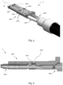
Figure 5 depicts aconnector assembly 1 with thecartridge 500 ofFig. 4 and the contact terminals 300,300' ofFig 3 in a perspective view. The contact terminals 300,300' are arranged at the end of the wires 400,400'. Thecartridge 500 was engaged with the contact terminals 300,300' by moving it relative to the contact terminals 300,300' in a direction perpendicular to themating axis 10. This way, the protrusions 304,304' are inserted precisely into the throughholes 504. When the contact terminals 300,300' are assembled with thecartridge 500, the throughholes 504 engage with the protrusions 304,304' to inhibit rotational and axial displacement of the contact terminals 300,300' relative to thecartridge 500 in assembled condition. The throughholes 504 allow mounting of the contact terminals 300,300' with thecartridge 500 only in a mounting direction perpendicular to themating axis 10. Thecartridge 500 does not fully enclose the terminals 300,300' as the cartridge is open to receive the contact terminals 300,300' from the opposite side of the throughholes 504. - When the
contact terminals 300, 300' are assembled with thecartridge 500, the throughholes 504 securely engage with theprotrusions 304, 304', preventing rotational and axial displacement of thecontact terminals 300, 300' relative to thecartridge 500 in the assembled condition. The design of the throughholes 504 ensures that thecontact terminals 300, 300' can only be mounted to thecartridge 500 in a direction perpendicular to themating axis 10. Thecartridge 500 is designed to be open, allowing it to receive thecontact terminals 300, 300' from the side opposite the throughholes 504, meaning it does not fully enclose theterminals 300, 300'. -
Figure 6 shows theconnector assembly 1 ofFig. 5 in a cross-sectional view. Thecontact terminal 300 is arranged at the end of thewire 400. Thecartridge 500 contains thecontact terminal 300, so that theprotrusion 304 is seated in the throughhole 504, thus inhibiting axial and rotational movement. - The
cartridge 500 holds thecontact terminal 300 such that theprotrusion 304 is securely seated in the throughhole 504. This configuration inhibits both axial and rotational movement of thecontact terminal 300 within thecartridge 500, ensuring a stable and reliable connection. -
Figure 7 illustrates aconnector assembly 3 where acartridge 600 is mounted in aconnector housing 700 in a cross-sectional view. Theconnector housing 700 comprises aguide groove 702 to engage with thecartridge 600. - The
guide groove 702 ensures proper alignment and secure positioning of thecartridge 600 within thehousing 700, facilitating accurate assembly and stable performance of theconnector assembly 3. The engagement of theguide groove 702 with thecartridge 600 also inhibits rotational movement of the cartridge in thehousing 700. -
Figure 8A depicts a connector assembly 4 with aconnector housing 800 with oneguide ridge 804 in a cross-sectional view. Acartridge 900 holds thecontact terminals 300, 300' and engages with theguide ridge 804 which inhibits rotational movement of thecartridge 900 in theconnector housing 800 and facilitates inserting of thecartridge 900 into theconnector housing 800. - This engagement inhibits rotational movement of the
cartridge 900 within theconnector housing 800 and facilitates the insertion of thecartridge 900 into theconnector housing 800, ensuring proper alignment and stability of the assembly. -
Figure 8B depicts a connector assembly 5 with aconnector housing 1100 with twoguide grooves 1102 in a cross-sectional view. Acartridge 1000 holds thecontact terminals 300, 300' and engages with theguide grooves 1102 which both inhibit rotational movement of thecartridge 1000 and facilitate inserting of thecartridge 1000 into theconnector housing 1100. - The
guide grooves 1102 inhibit rotational movement of thecartridge 1000 and facilitate the insertion of thecartridge 1000 into theconnector housing 1100, ensuring proper alignment and stability of the connector assembly 5. -
- 1, 2, 3, 4, 5: connector assembly
- 10: mating axis
- 100, 500, 600, 900: cartridge
- 102: latching means
- 104: ribs
- 200, 200', 300, 300': contact terminal
- 202, 202': slot
- 204, 204', 304, 304': protrusion
- 400, 400': wires
- 504: through holes
- 700, 800, 1100: connector housing
- 702, 1102: guide groove
- 804: guide ridge
Claims (13)
- A high-speed data transfer connector assembly (1, 2, 3, 4, 5) comprising:at least two signal transmission wires (400,400'), each being provided with a contact terminal;a cartridge (100, 500, 600, 900) adapted to retain the two signal transmission wires (400,400'), the cartridge (100, 500, 600, 900) comprising:the assembly further comprises a connector housing (700,800,1100) adapted to receive the cartridge (100, 500, 600, 900) therein.
attachment means to mount the contact terminals (200,200',300,300') onto the cartridge (100, 500, 600, 900), such that the contact terminals (200,200',300,300') are in a defined relative orientation to each other; wherein - A high-speed data transfer connector assembly (1, 2, 3, 4, 5) according to claim 1, wherein the cartridge (100, 500, 600, 900) comprises stopping means adapted to inhibit axial and/or rotational movement of the mounted contact terminals (200,200',300,300').
- A high-speed data transfer connector assembly (1, 2, 3, 4, 5) according to claim 1 or 2, wherein the attachment means comprise latching means (102), to enable a snap-fit connection with the terminals.
- A high-speed data transfer connector assembly (1, 2, 3, 4, 5) according to any one of the preceding claims, wherein the contact terminals (200,200',300,300') comprise at least one protrusion (204,204',304,304') extending perpendicular from the mating axis (10).
- A high-speed data transfer connector assembly (1, 2, 3, 4, 5) according to any one of the preceding claims, wherein the contact terminals (200,200',300,300') comprise at least one slot extending in a plane perpendicular to the mating axis (10).
- A high-speed data transfer connector assembly (1, 2, 3, 4, 5) according to claim 4 in combination with claim 5, wherein at least one slot and at least one protrusion (204,204',304,304') are directly adjacent to each other.
- A high-speed data transfer connector assembly (1, 2, 3, 4, 5) according to any one of claims 4 to 6, wherein the attachment means of the cartridge (100, 500, 600, 900) are adapted to engage with the protrusion(s) (204,204',304,304') and/or the slot(s) of the contact terminals (200,200',300,300'), and to inhibit rotational and axial displacement of the contact terminals (200,200',300,300') relative to the cartridge (100, 500, 600, 900) in assembled condition.
- A high-speed data transfer connector assembly (1, 2, 3, 4, 5) according to any one of the preceding claims, wherein the cartridge (100, 500, 600, 900) comprises attachment means adapted for an assembly process that allows mounting of the contact terminals (200,200',300,300') with the cartridge (100, 500, 600, 900) only in a mounting direction perpendicular to the mating axis (10).
- A high-speed data transfer connector assembly (1, 2, 3, 4, 5) according to any one of the preceding claims in combination with claim 5, wherein the attachment means comprise ribs (104) extending in a plane perpendicular to the mating axis (10), the ribs (104) being adapted to engage with the slots (202,202') of the contact terminals (200,200',300,300'), to fix the slots (202,202') in axial direction.
- A high-speed data transfer connector assembly (1, 2, 3, 4, 5) according to any of the claims 2 to 9, wherein the stopping means comprise blind holes and/or through holes (504), adapted to engage with the protrusion(s) (204,204',304,304') of the contact terminals (200,200',300,300').
- A high-speed data transfer connector assembly (1, 2, 3, 4, 5) according to any one of the preceding claims, wherein the cartridge (100, 500, 600, 900) and/or the connector housing (700,800,1100) comprises guide means adapted to facilitate inserting of the cartridge (100, 500, 600, 900) into the housing and to inhibit rotational movement of the cartridge (100, 500, 600, 900) when the cartridge (100, 500, 600, 900) is received in the housing.
- A high-speed data transfer connector assembly (1, 2, 3, 4, 5) according to the preceding claim, wherein the guide means comprise guide ridges (804) and/or guide grooves (702,1102) extending in mating direction.
- A high-speed data transfer connector assembly (1, 2, 3, 4, 5) according to any one of the preceding claims, wherein the cartridge (100, 500, 600, 900) does not fully enclose the terminals.
Applications Claiming Priority (3)
| Application Number | Priority Date | Filing Date | Title |
|---|---|---|---|
| IN202341053238 | 2023-08-08 | ||
| US18/439,085 US20240275096A1 (en) | 2023-02-13 | 2024-02-12 | Electrical connector with inner terminal cartridge for paired wire cables |
| EP24157252.8A EP4415182A1 (en) | 2023-02-13 | 2024-02-13 | Electrical connector with inner terminal cartridge for paired wire cables |
Publications (1)
| Publication Number | Publication Date |
|---|---|
| EP4507132A1 true EP4507132A1 (en) | 2025-02-12 |
Family
ID=92142022
Family Applications (1)
| Application Number | Title | Priority Date | Filing Date |
|---|---|---|---|
| EP24193325.8A Pending EP4507132A1 (en) | 2023-08-08 | 2024-08-07 | High speed inner terminal cartridge with twist relief |
Country Status (1)
| Country | Link |
|---|---|
| EP (1) | EP4507132A1 (en) |
Citations (3)
| Publication number | Priority date | Publication date | Assignee | Title |
|---|---|---|---|---|
| US20130288522A1 (en) * | 2012-04-26 | 2013-10-31 | Yazaki Corporation | Shielded connector |
| EP3723212A1 (en) * | 2019-04-11 | 2020-10-14 | Aptiv Technologies Limited | Network connector module for a network connector |
| US11296449B2 (en) * | 2020-04-30 | 2022-04-05 | Lear Corporation | Electrical connector assembly having identical electrical connectors |
-
2024
- 2024-08-07 EP EP24193325.8A patent/EP4507132A1/en active Pending
Patent Citations (3)
| Publication number | Priority date | Publication date | Assignee | Title |
|---|---|---|---|---|
| US20130288522A1 (en) * | 2012-04-26 | 2013-10-31 | Yazaki Corporation | Shielded connector |
| EP3723212A1 (en) * | 2019-04-11 | 2020-10-14 | Aptiv Technologies Limited | Network connector module for a network connector |
| US11296449B2 (en) * | 2020-04-30 | 2022-04-05 | Lear Corporation | Electrical connector assembly having identical electrical connectors |
Similar Documents
| Publication | Publication Date | Title |
|---|---|---|
| US6305961B1 (en) | EMI gasket for connector assemblies | |
| JP2992939B2 (en) | Electric terminal | |
| US6315620B1 (en) | System, method, and device for a pre-loaded straddle mounted connector assembly | |
| US20230013147A1 (en) | Compact electrical connector | |
| US20060276061A1 (en) | Connector | |
| US8727815B1 (en) | Compliant pin connector mounting system and method | |
| US10680363B2 (en) | Card edge connector assembly | |
| US11398694B2 (en) | Flex jumper assembly for a plug connector assembly | |
| CN101359785A (en) | connector terminal | |
| US6210224B1 (en) | Electrical connector | |
| US6113415A (en) | Electrical connector for connecting at least two plugs to a common socket | |
| US20240322465A1 (en) | High density card edge connector with hybrid interface | |
| CN110034433B (en) | Card Edge Connector Assembly | |
| CN212392412U (en) | Board end connector and connector assembly | |
| US6518506B2 (en) | Insulating body for a connector for the transmission of optical and electrical signals | |
| US20070155227A1 (en) | Electrical connector | |
| CN201966394U (en) | Electric connector | |
| US6761586B2 (en) | Board connector and method of attaching board connector | |
| CN219998546U (en) | High adaptability is lock pin for connector | |
| US6203381B1 (en) | Electrical connector | |
| TWI898728B (en) | Connector | |
| TWI902228B (en) | Floating card edge connector | |
| CN222705885U (en) | Electrical connector | |
| CN115715447A (en) | Electrical connector with stabilization features | |
| JP3250840U (en) | connector |
Legal Events
| Date | Code | Title | Description |
|---|---|---|---|
| PUAI | Public reference made under article 153(3) epc to a published international application that has entered the european phase |
Free format text: ORIGINAL CODE: 0009012 |
|
| STAA | Information on the status of an ep patent application or granted ep patent |
Free format text: STATUS: THE APPLICATION HAS BEEN PUBLISHED |
|
| AK | Designated contracting states |
Kind code of ref document: A1 Designated state(s): AL AT BE BG CH CY CZ DE DK EE ES FI FR GB GR HR HU IE IS IT LI LT LU LV MC ME MK MT NL NO PL PT RO RS SE SI SK SM TR |
|
| STAA | Information on the status of an ep patent application or granted ep patent |
Free format text: STATUS: REQUEST FOR EXAMINATION WAS MADE |
|
| 17P | Request for examination filed |
Effective date: 20250811 |