EP4507129A1 - Electrical connector with modular inserts and assembly method thereof - Google Patents
Electrical connector with modular inserts and assembly method thereof Download PDFInfo
- Publication number
- EP4507129A1 EP4507129A1 EP23190901.1A EP23190901A EP4507129A1 EP 4507129 A1 EP4507129 A1 EP 4507129A1 EP 23190901 A EP23190901 A EP 23190901A EP 4507129 A1 EP4507129 A1 EP 4507129A1
- Authority
- EP
- European Patent Office
- Prior art keywords
- electrical connector
- terminal
- electrical
- insert
- locking
- Prior art date
- Legal status (The legal status is an assumption and is not a legal conclusion. Google has not performed a legal analysis and makes no representation as to the accuracy of the status listed.)
- Pending
Links
Images




Classifications
-
- H—ELECTRICITY
- H01—ELECTRIC ELEMENTS
- H01R—ELECTRICALLY-CONDUCTIVE CONNECTIONS; STRUCTURAL ASSOCIATIONS OF A PLURALITY OF MUTUALLY-INSULATED ELECTRICAL CONNECTING ELEMENTS; COUPLING DEVICES; CURRENT COLLECTORS
- H01R13/00—Details of coupling devices of the kinds covered by groups H01R12/70 or H01R24/00 - H01R33/00
- H01R13/40—Securing contact members in or to a base or case; Insulating of contact members
- H01R13/42—Securing in a demountable manner
- H01R13/436—Securing a plurality of contact members by one locking piece or operation
- H01R13/4364—Insertion of locking piece from the front
-
- H—ELECTRICITY
- H01—ELECTRIC ELEMENTS
- H01R—ELECTRICALLY-CONDUCTIVE CONNECTIONS; STRUCTURAL ASSOCIATIONS OF A PLURALITY OF MUTUALLY-INSULATED ELECTRICAL CONNECTING ELEMENTS; COUPLING DEVICES; CURRENT COLLECTORS
- H01R13/00—Details of coupling devices of the kinds covered by groups H01R12/70 or H01R24/00 - H01R33/00
- H01R13/40—Securing contact members in or to a base or case; Insulating of contact members
- H01R13/42—Securing in a demountable manner
- H01R13/424—Securing in base or case composed of a plurality of insulating parts having at least one resilient insulating part
-
- H—ELECTRICITY
- H01—ELECTRIC ELEMENTS
- H01R—ELECTRICALLY-CONDUCTIVE CONNECTIONS; STRUCTURAL ASSOCIATIONS OF A PLURALITY OF MUTUALLY-INSULATED ELECTRICAL CONNECTING ELEMENTS; COUPLING DEVICES; CURRENT COLLECTORS
- H01R43/00—Apparatus or processes specially adapted for manufacturing, assembling, maintaining, or repairing of line connectors or current collectors or for joining electric conductors
- H01R43/20—Apparatus or processes specially adapted for manufacturing, assembling, maintaining, or repairing of line connectors or current collectors or for joining electric conductors for assembling or disassembling contact members with insulating base, case or sleeve
-
- H—ELECTRICITY
- H01—ELECTRIC ELEMENTS
- H01R—ELECTRICALLY-CONDUCTIVE CONNECTIONS; STRUCTURAL ASSOCIATIONS OF A PLURALITY OF MUTUALLY-INSULATED ELECTRICAL CONNECTING ELEMENTS; COUPLING DEVICES; CURRENT COLLECTORS
- H01R13/00—Details of coupling devices of the kinds covered by groups H01R12/70 or H01R24/00 - H01R33/00
- H01R13/40—Securing contact members in or to a base or case; Insulating of contact members
- H01R13/42—Securing in a demountable manner
- H01R13/422—Securing in resilient one-piece base or case, e.g. by friction; One-piece base or case formed with resilient locking means
- H01R13/4223—Securing in resilient one-piece base or case, e.g. by friction; One-piece base or case formed with resilient locking means comprising integral flexible contact retaining fingers
-
- H—ELECTRICITY
- H01—ELECTRIC ELEMENTS
- H01R—ELECTRICALLY-CONDUCTIVE CONNECTIONS; STRUCTURAL ASSOCIATIONS OF A PLURALITY OF MUTUALLY-INSULATED ELECTRICAL CONNECTING ELEMENTS; COUPLING DEVICES; CURRENT COLLECTORS
- H01R13/00—Details of coupling devices of the kinds covered by groups H01R12/70 or H01R24/00 - H01R33/00
- H01R13/46—Bases; Cases
- H01R13/502—Bases; Cases composed of different pieces
- H01R13/506—Bases; Cases composed of different pieces assembled by snap action of the parts
-
- H—ELECTRICITY
- H01—ELECTRIC ELEMENTS
- H01R—ELECTRICALLY-CONDUCTIVE CONNECTIONS; STRUCTURAL ASSOCIATIONS OF A PLURALITY OF MUTUALLY-INSULATED ELECTRICAL CONNECTING ELEMENTS; COUPLING DEVICES; CURRENT COLLECTORS
- H01R13/00—Details of coupling devices of the kinds covered by groups H01R12/70 or H01R24/00 - H01R33/00
- H01R13/46—Bases; Cases
- H01R13/52—Dustproof, splashproof, drip-proof, waterproof, or flameproof cases
- H01R13/5202—Sealing means between parts of housing or between housing part and a wall, e.g. sealing rings
-
- H—ELECTRICITY
- H01—ELECTRIC ELEMENTS
- H01R—ELECTRICALLY-CONDUCTIVE CONNECTIONS; STRUCTURAL ASSOCIATIONS OF A PLURALITY OF MUTUALLY-INSULATED ELECTRICAL CONNECTING ELEMENTS; COUPLING DEVICES; CURRENT COLLECTORS
- H01R13/00—Details of coupling devices of the kinds covered by groups H01R12/70 or H01R24/00 - H01R33/00
- H01R13/64—Means for preventing incorrect coupling
- H01R13/645—Means for preventing incorrect coupling by exchangeable elements on case or base
-
- H—ELECTRICITY
- H01—ELECTRIC ELEMENTS
- H01R—ELECTRICALLY-CONDUCTIVE CONNECTIONS; STRUCTURAL ASSOCIATIONS OF A PLURALITY OF MUTUALLY-INSULATED ELECTRICAL CONNECTING ELEMENTS; COUPLING DEVICES; CURRENT COLLECTORS
- H01R2201/00—Connectors or connections adapted for particular applications
- H01R2201/26—Connectors or connections adapted for particular applications for vehicles
Definitions
- the present invention relates to an electrical connector with caged modular inserts.
- the electrical connector is particularly useful as female connector for a high-speed data connector system for automotive applications.
- Electrical connectors are widely used in automotive applications. On the one hand such electrical connectors are used to transmit electrical power to electric consumers. On the other hand electric connectors are more often used to distribute data in automotive vehicles.
- Vehicles are adding high-resolution radars and cameras to support ever more sophisticated automated driving capabilities, and those devices create high-bandwidth streams of data to centralized computing platforms.
- networking technologies such as Automotive Ethernet and MIPI A-PHY, a new physical-layer interface for in-vehicle data transmission.
- Ethernet has a long and successful history in IT, but the most common connectors used with Ethernet in the IT world-such as the RJ-45 jack found on many laptops and in data centers-are not nearly robust enough for automotive environments, which present unique challenges related to heat, vibration, electromagnetic interference, space constraints, dirt and dust. Keeping the connections clean and securely attached in that environment is critical to ensuring that the automated driving features operate as expected.
- a high-speed data connector system is a connector system used in automotive networking applications that supports frequencies up to 20 GHz and data transmission rates up to 56G bit/sec. To protect against electromagnetic interference, the connectors provide a fully shielded interface.
- the high-speed data connector system cable assembly design supports the use of shielded twisted-pair cables for high bandwidths.
- An example of a high-speed data connector system is the H-MTD ® connector system of the company Rosenberger Hochfrequenztechnik GmbH und Co. KG, Germany.
- the object of the present invention is to provide an electrical connector, particularly for high-bandwidth data applications, that is easy to assemble, reliable, easily serviceable, preferably easy serviceable with standard tools and robust enough for automotive applications.
- an electrical connector comprising an outer housing defining a mating direction of the female electrical connector; at least one electrical terminal; at least one insert, individually surrounding the at least one electrical terminal; wherein the insert comprises a terminal locking means for selectively locking the electrical terminal within the insert; wherein the terminal locking means is an integral part of the insert and is switchable between an assembly position in which the electrical terminal is insertable into the electrical connector and a locking position in which the electrical terminal is locked within the electrical connector by the terminal locking means.
- each electrical terminal is individually surrounded by its insert, what makes the female electrical connector modular in terms of the number of female electrical terminals.
- one female electrical terminal can comprise more than one electrical contact.
- two electrical contacts for the twisted pair cable are provided in one electrical terminal.
- the high-speed data connector system terminal provides a common shielding for the two electrical contacts of the twisted pair cable.
- the electrical terminal for a coaxial cable can only comprise one electrical contact, that is shielded by an outer shield.
- the electrical contacts can be female or male.
- the electrical connector can be a female or male electrical connector, particularly a female or male electrical connector for a high-speed data connector system.
- the terminal locking means provides secure locking of the electrical terminal within the electrical connector. Since the terminal locking means is an integral part of the insert it cannot be lost but is still movable in respect to the body of the insert. Further, no additional part is needed. Since the terminal locking means is switchable between an assembly position and a locking position, an easy assembly of the electrical terminal and a secure locking of the female electrical terminal within the female electrical connector is ensured, simply by moving the terminal locking means between these two positions. By being switchable the terminal locking means remains stable in the two positions. Thus, it adopts either the assembly position or the locking position but is not stable in-between. This on the one hand facilitates insertion of the electrical terminal and on the other hand reliably ensures mounting of the electrical terminal within the electrical connector. Further, since the terminal locking means can be switched between both positions a plurality of times, it is possible to easily disassemble the electrical terminal from the electrical connector. This allows servicing or adapting the electrical connection if needed.
- the terminal locking means has a locking protrusion that moves essentially perpendicularly to the mating direction when switching between the assembly position and the locking position.
- the locking protrusion reliably resists a pulling force onto the electrical terminal, since such pulling force is essentially perpendicularly to the switching movement of the locking protrusion.
- the terminal locking means has a latching protrusion, that latches with a latching rim of the insert in the locking position.
- the latching protrusion remains stable in the locking position.
- the latching protrusion of the terminal locking means additionally abuts the latching rim of the insert in the assembly position.
- the latching protrusion also remains stable in the assembly position.
- the terminal locking means comprises an integral un-locking lever at the locking protrusion, for switching the terminal locking means from the locking position to the assembly position.
- the un-locking lever facilitates an easy switching the locking protrusion into the assembly position for a simple removal of the electrical terminal out of the electrical connector.
- the un-locking lever can preferably be actuated by a manual tool.
- the un-locking lever is shaped to be switched from the locking position to the assembly position by means of a flat screwdriver.
- the terminal locking means further comprises a film hinge that connects the locking protrusion with a body of the insert, wherein the film hinge provides movement of the locking protrusion.
- the film hinge provides a reliable and easy movable connection between the locking protrusion and the insert.
- the film hinge supports defining the movement direction of the locking protrusion and provides elasticity for the switching between the assembly and the locking position.
- the insert further comprises a latching arm for latching with the outer housing.
- the latching arm extends from the body of the insert in negative mating direction.
- the outer housing comprises at least one lock lance for latching with the electrical terminal.
- the lock lance provides a first locking feature for mounting the electrical terminal within the electrical connector after insertion in mating direction.
- the electrical connector further comprises a cage inner housing, connected to the inside of the outer housing, extending in mating direction out of the outer housing, and surrounding the at least one insert in mating direction. Since the cage inner housing extends in mating direction out of the outer housing and surrounds the at least one insert in mating direction it mechanically protects the insert prior and after assembly of the respective female electrical terminal. Preferably, the cage inner housing builds a protective "cage" around the insert during use.
- the cage inner housing comprises a switching tab that switches the terminal locking means from the assembly position to the locking position, when the cage inner housing is inserted into the outer housing.
- the cage inner housing automatically switches and/or secures the terminal locking means to the locking position.
- the electrical terminal is secured by the cage inner housing as the switching tab blocks the terminal locking means in the locked position.
- the cage inner housing comprises coding features for allowing connection with a suitable corresponding electrical connector of different gender and for preventing a connection with a non-suitable electrical connector.
- the cage inner housing is connected to the outer housing by a retaining latch of the cage inner housing.
- the cage inner housing can be attached to the housing by simple insertion in mounting direction and latching.
- the cage inner housing comprising a release hook attached to the retaining latch for releasing the retaining latch by a tool.
- the cage inner housing can be disassembled from the electrical connector if necessary.
- the cage inner housing can be disassembled from the electrical connector in case the electrical terminals need to be disassembled.
- the electrical connector further comprises an elastic seal, wherein the seal has a V-shaped cross-section and is arranged between the outer housing and the cage inner housing.
- the seal waterproofs the connection between the outer housing and the cage inner housing.
- the seal also waterproofs the connection between the electrical connector and an electrical connector of different gender connected to the electrical connector. The two legs of the V-shaped cross-section, thus, provide two sealing surfaces of the seal.
- the seal comprises ridges at both sealing surfaces, which improve the sealing performance.
- the cage inner housing comprises a tubular end that introduces into a cavity formed by the V-shaped cross-section of the elastic seal.
- the cage inner housing holds the seal in place and reinforces the seal.
- the terminal is a high-speed data terminal, preferably a shielded coaxial terminal or a shielded high-speed modular twisted pair data terminal.
- the electrical connector is suitable for high-bandwidth data transmission.
- the electrical connector comprises more than one, preferably two, three, four, five or six electrical terminals, and correspondingly more than one, preferably two, three, four, five or six inserts.
- each of the electrical terminals can individually be assembled or locked by the corresponding insert.
- the electrical connector 1 is preferably a female electrical connector and comprises as main components an outer housing 10, six female electrical terminals 20, a cage inner housing 50, and six inserts 30. Each of the six inserts 30 have a terminal locking means 40 for individually locking the respective electrical terminal 20 within the electrical connector 1.
- the electrical connector 1 preferably comprises an elastic seal 60 that is arranged between the outer housing 10 and the cage inner housing 50.
- the electrical terminals 20 are electrically and mechanically connected to corresponding electrical cables 90.
- the female electrical connector 1 preferably comprises for each of the cables 90 cable seals (not shown) that are arranged between each of the cables 90 and cable receptacles 16 of the outer housing 10.
- the female electrical connector 1 further preferably comprises a latching tab for latching with a corresponding male electrical connector (not shown).
- the electrical connector 1 comprises a connector side 2 where it connects with a corresponding electrical connector of different gender (not shown) and a cable side 4 where the electrical cables 90 extend.
- the mating direction is indicated by an arrow X and shows the movement direction for establishing connection with a corresponding electrical connector of different gender (not shown).
- the electrical connector 1 is a female connector for a high-speed data connector system for automotive applications.
- the electrical connector 1 can be a H-MTD ® type female electrical connector.
- the electrical connector 1 comprises six female electrical terminals 20 each one for one shielded twisted pair high-speed data cable 90.
- each electrical terminal 20 is shielded by a metal shield 22 and comprises two female electrical contacts 24, one for each line of the twisted pair cable 90 (see also Fig. 8B ).
- the electrical connector 1 can comprise only one or up to six or even more female electrical terminals 20 for two, three, four, five or up to six or even more twisted pair cables 90 with up to twelve or even more individual electrical data lines.
- the female electrical connector 1 can comprise four female electrical terminals 20 with eight individual electrical data lines and eight female electrical contacts 24.
- the electrical connector 1 could also be a male electrical connector 1 with male electrical terminals 20 and male electrical contacts 24.
- the electrical connector 1 provides a robust, reliable and preferably water-resistant connector for shielded high-speed twisted-pair data cables. Thereby, the electrical terminals 20 are reliably individually locked within the electrical connector 1. Since the outer housing 10 is a one-piece element the electrical terminals 20 are held exactly in place, what improves contact overlap of the electrical connection. In addition, the electrical terminals 20 can be individually removed from the electrical connector 1, when the locking is released. All locking elements of the electrical connector 1 are caged in the inside of the electrical connector 1 by the cage inner housing 50, what prevents any unintentional unlocking of the female electrical terminals 20. The locking of the electrical terminals can be done with a standard manual tool or preferably tool-less. For the unlocking of the electrical terminals 20 only a standard manual tool 100 (see Figs. 12-14 ) is needed, such that disassembly of the electrical connector 1 can be done without any damaging.
- Each electrical terminal 20 is individually surrounded by a corresponding insert 30, which is shown in detail in Figs. 4A-C .
- the inserts 30 comprise an essentially hollow body 32 that in assembled condition surrounds one of the electrical terminals 20. Further, the inserts 30 comprise a latching arm 36 for latching with the outer housing 10.
- the inserts 30 comprise a terminal locking means 40 for selectively locking the electrical terminal 20 within the insert 30.
- the terminal locking means 40 is integrally formed with the insert 30 and comprises a film hinge 47 that connects a locking protrusion 43 to the body 32 of the insert 30.
- the film hinge 47 provides that the locking protrusion 43 can move essentially perpendicular to the mating direction X of the electrical connector 1.
- the terminal locking means 40 is switchable between an assembly position 41 (see Fig. 5A ) in which the electrical terminal 20 is insertable into the electrical connector 1 and a locking position 42 (see Fig. 5B ) in which the electrical terminal 20 is locked within the electrical connector 1 by the terminal locking means 40.
- the two positions of the terminal locking means 40 are stably maintained after switching to increase reliability of the assembly.
- the terminal locking means 40 comprises a latching protrusion 44, that latches with a latching rim 34 of the insert 30 in the locking position 42.
- the latching protrusion 44 of the terminal locking means 40 abuts the latching rim 34 of the insert 30 in the assembly position 41.
- the terminal locking means 40 does not accidentally switch between the assembly position 41 and the locking position 42 and vice versa.
- the terminal locking means 40 is generally hook-shaped to lock with the latching rim 34 either in the assembly position 41 or in the locking position 42.
- the switching of the terminal locking means 40 can be done manually by a simple tool, for example by a screwdriver 100. However, the terminal locking means 40 can also switch automatically to the locking position 42 during assembly of the electrical connector 1.
- Fig. 6A shows the insert 30 when a terminal 20 is inserted.
- the terminal locking means 40 is still in the assembly position 41, where the locking protrusion 43 is switched to the outside of the insert 30 and the latching protrusion 44 abuts the latching rim 34. In this assembly position 41 the electrical terminal 20 could be pulled out of the insert 30.
- the terminal locking means 40 is switched to the locking position 42, as shown in Fig. 6B the locking protrusion is switched to the inside of the insert 30 and blocks a rear edge 26 of the metal shield 22 of the electrical terminal 20.
- the electrical terminal 20 is locked within the insert 30.
- the terminal locking means 40 comprises an integral unlocking lever 46 that can be actuated by a manual tool, for example by screwdriver 100 (see Fig. 12A-C ).
- the un-locking lever 46 preferably extends perpendicularly to the mating direction to one side of the locking protrusion 43.
- Figs. 7A to 11B show the assembly process of the electrical connector in detail.
- the inserts 30 are introduced against mating direction X into corresponding receptacles 18 (see Fig. 3 ) of the outer housing 1.
- the latching arm 36 latches with a latching hook 12 of the outer housing 10.
- each of the inserts 30 is secured within the outer housing 10.
- the electrical terminals 20 are inserted into the inserts 30. This is done in mating direction X from the cable side 4 of the electrical connector 1.
- the elastic lock lance 14 of the outer housing 10 latches with the electrical terminal 20 and locks it in place.
- the lock lance 14 snaps behind the rear edge 26 of the metal shield 22 and locks the electrical terminal 20 in assembled position.
- the electrical terminal 20 is additionally locked in the insert 30 by switching the terminal locking means 40 from the assembly position 41 (see Fig. 9A ) to the locking position 42 (see Fig. 9B ).
- the locking projection 43 moves also behind the rear edge 26 of the metal shield 22 and additionally locks the electrical terminal 20 in assembled position.
- the switching of the terminal locking means 40 can be done manually or automatically by the assembly of the cage inner housing 50.
- a cage inner housing 50 is shown in Fig. 10A in detail.
- the cage inner housing 50 protects all inserts 30 of the electrical connector 1.
- the shown cage inner housing 50 comprises an essentially hollow body and openings or cavities 58 for each of the inserts 30 and electrical terminals 20.
- the cage inner housing 50 is rigidly connected to the outer housing 10 by a retaining latch 52 that latches with a latch or pocket of the outer housing (see Figs. 10B and 10C ).
- the cage inner housing 50 further comprises coding features 51 for allowing connection with a suitable electrical connector of different gender (not shown) and for preventing a connection with a non-suitable electrical connector (not shown).
- the coding features 51 comprise a plurality of ribs that are arranged in mating direction X.
- the cage inner housing further comprises an essentially tubular end 56 that during assembly enters into the cavity 64 of the elastomeric seal 60 (see Figs. 11A and 11B ).
- the cage inner housing 50 further comprises switching tabs 57.
- the switching tabs 57 move downwards and thereby switch the terminal locking means 40 from the assembly position 41 to the locking position 42 (see Fig. 11B ).
- the terminal locking means 40 is automatically switched and secured in the locking position 42 by the cage inner housing 50.
- Fig. 11A and 11B also show details of the elastomeric seal 60. It is made of an elastomeric material and seals the connector side cavity to a male electrical connector (not shown) and simultaneously between the outer housing 10 and the cage inner housing 50.
- the elastomeric seal 60 is essentially annular and has a V-shaped cross section 62.
- the V-shaped cross-section 62 forms an inner sealing wall 65, an outer sealing wall 66 and an annular cavity 64 in-between the sealing walls 65, 66.
- the elastomeric seal 60 further comprises inner rims 67 that extend from an inner sealing wall 65 to the inside and outer rims 68 that extend from the outer sealing wall 66.
- the rims 67, 68 further improve the tightness of the final connection.
- the electrical connector 1 can also be disassembled without any damage, as shown in in Figs. 12A to 14B .
- a first disassembly step the cage inner housing 50 is disassembled from the electrical connector 1.
- the retaining latches 52 are bent outwards by manual tools, e.g. a flat screwdriver that engages a release hook 54 at the outside of the retaining latch 52 (see. Fig.10A-C ). This disengages the retaining latch 52 from the outer housing 10 and allows the cage inner housing 50 to be removed.
- a manual tool 100 e.g. a flat screwdriver 100 engages behind the un-locking lever 46 of each of the terminal locking means 40 to move them from the locking position 41 (see Fig. 12A ) outwards to the assembly position (see Fig. 12C ).
- a third disassembly step as shown in Fig. 13 the manual tool 100 can be used to bend the elastic lock lance 14 of the outer housing 10 outwards to release the electric terminal 20 from engagement. Then the electric terminal 20 can be pulled out of the electric connector 1 .
Landscapes
- Engineering & Computer Science (AREA)
- Manufacturing & Machinery (AREA)
- Details Of Connecting Devices For Male And Female Coupling (AREA)
Abstract
Electrical connector 1 comprising an outer housing to defining a mating direction X of the female electrical connector 1; at least one electrical terminal 20; at least one insert 30, individually surrounding the at least one electrical terminal 20; wherein the insert 30 comprises a terminal locking means 40 for selectively locking the electrical terminal 20 within the insert 30; wherein the terminal locking means 40 is an integral part of the insert 30 and is switchable between an assembly position 41 in which the electrical terminal 20 is insertable into the electrical connector 1 and a locking position 42 in which the electrical terminal 20 is locked within the electrical connector 1 by the terminal locking means 40. The application further comprises a method for an assembly of an electrical connector 1.
Description
- The present invention relates to an electrical connector with caged modular inserts. The electrical connector is particularly useful as female connector for a high-speed data connector system for automotive applications.
- Electrical connectors are widely used in automotive applications. On the one hand such electrical connectors are used to transmit electrical power to electric consumers. On the other hand electric connectors are more often used to distribute data in automotive vehicles.
- Vehicles are adding high-resolution radars and cameras to support ever more sophisticated automated driving capabilities, and those devices create high-bandwidth streams of data to centralized computing platforms. To accommodate these emerging requirements, the industry is moving to networking technologies such as Automotive Ethernet and MIPI A-PHY, a new physical-layer interface for in-vehicle data transmission.
- Ethernet has a long and successful history in IT, but the most common connectors used with Ethernet in the IT world-such as the RJ-45 jack found on many laptops and in data centers-are not nearly robust enough for automotive environments, which present unique challenges related to heat, vibration, electromagnetic interference, space constraints, dirt and dust. Keeping the connections clean and securely attached in that environment is critical to ensuring that the automated driving features operate as expected.
- A high-speed data connector system is a connector system used in automotive networking applications that supports frequencies up to 20 GHz and data transmission rates up to 56G bit/sec. To protect against electromagnetic interference, the connectors provide a fully shielded interface. The high-speed data connector system cable assembly design supports the use of shielded twisted-pair cables for high bandwidths. An example of a high-speed data connector system is the H-MTD® connector system of the company Rosenberger Hochfrequenztechnik GmbH und Co. KG, Germany.
- The object of the present invention is to provide an electrical connector, particularly for high-bandwidth data applications, that is easy to assemble, reliable, easily serviceable, preferably easy serviceable with standard tools and robust enough for automotive applications.
- The above-mentioned object is realized by an electrical connector according to
claim 1 or by a method for an assembly of an electrical connector according to claim 15. - Particularly, the above-mentioned object is realized by an electrical connector comprising an outer housing defining a mating direction of the female electrical connector; at least one electrical terminal; at least one insert, individually surrounding the at least one electrical terminal; wherein the insert comprises a terminal locking means for selectively locking the electrical terminal within the insert; wherein the terminal locking means is an integral part of the insert and is switchable between an assembly position in which the electrical terminal is insertable into the electrical connector and a locking position in which the electrical terminal is locked within the electrical connector by the terminal locking means.
- Thus, each electrical terminal is individually surrounded by its insert, what makes the female electrical connector modular in terms of the number of female electrical terminals. It should be noted that one female electrical terminal can comprise more than one electrical contact. For example, in case of a high-speed data connector system terminal two electrical contacts for the twisted pair cable are provided in one electrical terminal. Preferably, the high-speed data connector system terminal provides a common shielding for the two electrical contacts of the twisted pair cable. In another example the electrical terminal for a coaxial cable can only comprise one electrical contact, that is shielded by an outer shield. The electrical contacts can be female or male. Thus, the electrical connector can be a female or male electrical connector, particularly a female or male electrical connector for a high-speed data connector system.
- The terminal locking means provides secure locking of the electrical terminal within the electrical connector. Since the terminal locking means is an integral part of the insert it cannot be lost but is still movable in respect to the body of the insert. Further, no additional part is needed. Since the terminal locking means is switchable between an assembly position and a locking position, an easy assembly of the electrical terminal and a secure locking of the female electrical terminal within the female electrical connector is ensured, simply by moving the terminal locking means between these two positions. By being switchable the terminal locking means remains stable in the two positions. Thus, it adopts either the assembly position or the locking position but is not stable in-between. This on the one hand facilitates insertion of the electrical terminal and on the other hand reliably ensures mounting of the electrical terminal within the electrical connector. Further, since the terminal locking means can be switched between both positions a plurality of times, it is possible to easily disassemble the electrical terminal from the electrical connector. This allows servicing or adapting the electrical connection if needed.
- Preferably, the terminal locking means has a locking protrusion that moves essentially perpendicularly to the mating direction when switching between the assembly position and the locking position. Thus, the locking protrusion reliably resists a pulling force onto the electrical terminal, since such pulling force is essentially perpendicularly to the switching movement of the locking protrusion.
- Preferably, the terminal locking means has a latching protrusion, that latches with a latching rim of the insert in the locking position. Thus, the latching protrusion remains stable in the locking position.
- Preferably, the latching protrusion of the terminal locking means additionally abuts the latching rim of the insert in the assembly position. Thus, the latching protrusion also remains stable in the assembly position.
- Preferably, the terminal locking means comprises an integral un-locking lever at the locking protrusion, for switching the terminal locking means from the locking position to the assembly position. The un-locking lever facilitates an easy switching the locking protrusion into the assembly position for a simple removal of the electrical terminal out of the electrical connector. The un-locking lever can preferably be actuated by a manual tool.
- Preferably, the un-locking lever is shaped to be switched from the locking position to the assembly position by means of a flat screwdriver. Thus, no special tools are needed for a disassembly of the electrical terminal.
- Preferably, the terminal locking means further comprises a film hinge that connects the locking protrusion with a body of the insert, wherein the film hinge provides movement of the locking protrusion. The film hinge provides a reliable and easy movable connection between the locking protrusion and the insert. Furthermore, the film hinge supports defining the movement direction of the locking protrusion and provides elasticity for the switching between the assembly and the locking position.
- Preferably, the insert further comprises a latching arm for latching with the outer housing. Preferably, the latching arm extends from the body of the insert in negative mating direction.
- Preferably, the outer housing comprises at least one lock lance for latching with the electrical terminal. The lock lance provides a first locking feature for mounting the electrical terminal within the electrical connector after insertion in mating direction.
- Preferably, the electrical connector further comprises a cage inner housing, connected to the inside of the outer housing, extending in mating direction out of the outer housing, and surrounding the at least one insert in mating direction. Since the cage inner housing extends in mating direction out of the outer housing and surrounds the at least one insert in mating direction it mechanically protects the insert prior and after assembly of the respective female electrical terminal. Preferably, the cage inner housing builds a protective "cage" around the insert during use.
- Preferably, the cage inner housing comprises a switching tab that switches the terminal locking means from the assembly position to the locking position, when the cage inner housing is inserted into the outer housing. Thus, the cage inner housing automatically switches and/or secures the terminal locking means to the locking position. Thereby, the electrical terminal is secured by the cage inner housing as the switching tab blocks the terminal locking means in the locked position.
- Preferably, the cage inner housing comprises coding features for allowing connection with a suitable corresponding electrical connector of different gender and for preventing a connection with a non-suitable electrical connector.
- Preferably, the cage inner housing is connected to the outer housing by a retaining latch of the cage inner housing. Thus, the cage inner housing can be attached to the housing by simple insertion in mounting direction and latching.
- Preferably, the cage inner housing comprising a release hook attached to the retaining latch for releasing the retaining latch by a tool. Thus, the cage inner housing can be disassembled from the electrical connector if necessary. Particularly, the cage inner housing can be disassembled from the electrical connector in case the electrical terminals need to be disassembled.
- Preferably, the electrical connector further comprises an elastic seal, wherein the seal has a V-shaped cross-section and is arranged between the outer housing and the cage inner housing. Preferably, the seal waterproofs the connection between the outer housing and the cage inner housing. In addition the seal also waterproofs the connection between the electrical connector and an electrical connector of different gender connected to the electrical connector. The two legs of the V-shaped cross-section, thus, provide two sealing surfaces of the seal.
- Preferably, the seal comprises ridges at both sealing surfaces, which improve the sealing performance.
- Preferably, the cage inner housing comprises a tubular end that introduces into a cavity formed by the V-shaped cross-section of the elastic seal. Thus, the cage inner housing holds the seal in place and reinforces the seal.
- Preferably, the terminal is a high-speed data terminal, preferably a shielded coaxial terminal or a shielded high-speed modular twisted pair data terminal. Thus, the electrical connector is suitable for high-bandwidth data transmission.
- Preferably, the electrical connector comprises more than one, preferably two, three, four, five or six electrical terminals, and correspondingly more than one, preferably two, three, four, five or six inserts. Thus, each of the electrical terminals can individually be assembled or locked by the corresponding insert.
- The above-mentioned problem is also solved by a method for an assembly of an electrical connector comprising the following steps:
- a. providing an outer housing defining a mating direction of the electrical connector;
- b. providing an insert within the electrical connector, wherein the insert comprises a terminal locking means as an integral part of the insert;
- c. providing a cage inner housing, connected to the inside of the outer housing, extending in mating direction out of the outer housing, and surrounding the at least one insert in mating direction;
- d. inserting at least one electrical terminal into a back side of the outer housing such that the electrical terminal is at least partially surrounded by the insert; and
- e. switching the terminal locking means from an assembly position in which the electrical terminal is insertable into the electrical connector to a locking position in which the electrical terminal is locked within the electrical connector by the terminal locking means.
- By this assembly method, the same advantages are achieved as explained above in view of the electrical connector.
- In the following, preferred embodiments of the invention are disclosed by reference to the accompanying figure, in which shows:
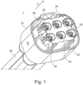
- Fig. 1
- a three-dimensional view of a preferred embodiment of an electrical connector;
- Fig. 2
- a sectional view of the electrical connector of
Fig. 1 ; - Fig. 3
- a partial three-dimensional explosion view of the electrical connector of
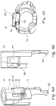
Fig. 1 ; - Figs. 4A-C
- different views of a preferred embodiment of an insert of the electrical connector of
Fig. 1 ; - Fig. 5A
- a three-dimensional view of the insert of
Figs. 4A-C with a terminal locking means in the assembly position; - Fig. 5B
- a three-dimensional view of the insert of
Figs. 4A-C with a terminal locking means in the locking-position; - Fig. 6A
- a side view of the insert of
Figs. 4A-C together with a preferred embodiment of an electrical terminal, with a terminal locking means in the assembly position; - Fig. 6B
- a side view of the insert of
Figs. 4A-C together with an electrical terminal, with a terminal locking means in the locking position; - Figs. 7A-C
- sectional side views of the insert of
Figs. 4A-C together with a preferred embodiment of an outer housing during the insertion of the insert into the outer housing; - Figs. 8A-B
- sectional side views of the assembly of
Figs. 7A-C during the insertion of an electrical terminal, whereinFig. 8B is rotated by 90° around the insertion direction versusFig. 8A ; - Figs. 8C-D
- sectional side views of the assembly of
Figs. 7A-C after the insertion of an electrical terminal, whereinFig. 8D is rotated by 90° around the insertion direction versusFig. 8C ; - Fig. 9A
- a sectional side view of the assembly of
Figs. 8A-C with a terminal locking means in the assembly position; - Fig. 9B
- a sectional side view of the assembly of
Figs. 8A-C with a terminal locking means in the locking position; - Fig. 10A
- a three-dimensional view of a preferred embodiment of a cage inner housing;
- Figs. 10B-Ca
- sectional side view and a three-dimensional side view of the cage inner housing of
Fig. 10C ; - Fig. 11A
- a partial sectional side view of the electrical connector of
Fig. 1 during assembly of the cage inner housing; - Fig. 11B
- a partial sectional side view of the electrical connector of
Fig. 1 after assembly of the cage inner housing; - Figs. 12A and C
- side views of the assembly of
Figs. 6A-B and a tool during switching of the terminal locking means from the locked position to the assembly position; - Fig. 12B
- a partial three-dimensional view of an electrical connector with removed cage inner housing during switching of the terminal locking means from the locked position to the assembly position by a manual tool;
- Fig. 13
- a partial three-dimensional view of the electrical connector of
Fig. 12B during release of a lock lance of the outer housing; - Figs. 14A-B
- a partial sectional side view and a three-dimensional view of the assembly of
Figs. 7A-C during the release of the insert by a manual tool. - In the following, preferred embodiments of the invention are described in detail with respect to the figures.
-
Figs. 1 ,2 and3 show anelectrical connector 1 according to a preferred embodiment of the present invention. Theelectrical connector 1 is preferably a female electrical connector and comprises as main components anouter housing 10, six femaleelectrical terminals 20, a cageinner housing 50, and six inserts 30. Each of the sixinserts 30 have a terminal locking means 40 for individually locking the respectiveelectrical terminal 20 within theelectrical connector 1. Further theelectrical connector 1 preferably comprises anelastic seal 60 that is arranged between theouter housing 10 and the cageinner housing 50. Theelectrical terminals 20 are electrically and mechanically connected to correspondingelectrical cables 90. Further, the femaleelectrical connector 1 preferably comprises for each of thecables 90 cable seals (not shown) that are arranged between each of thecables 90 andcable receptacles 16 of theouter housing 10. The femaleelectrical connector 1 further preferably comprises a latching tab for latching with a corresponding male electrical connector (not shown). - The
electrical connector 1 comprises aconnector side 2 where it connects with a corresponding electrical connector of different gender (not shown) and acable side 4 where theelectrical cables 90 extend. The mating direction is indicated by an arrow X and shows the movement direction for establishing connection with a corresponding electrical connector of different gender (not shown). - As particularly shown in
Fig. 2 , in the preferred embodiment theelectrical connector 1 is a female connector for a high-speed data connector system for automotive applications. Preferably, theelectrical connector 1 can be a H-MTD® type female electrical connector. Theelectrical connector 1 comprises six femaleelectrical terminals 20 each one for one shielded twisted pair high-speed data cable 90. Thus, eachelectrical terminal 20 is shielded by ametal shield 22 and comprises two femaleelectrical contacts 24, one for each line of the twisted pair cable 90 (see alsoFig. 8B ). Of course, in other embodiments theelectrical connector 1 can comprise only one or up to six or even more femaleelectrical terminals 20 for two, three, four, five or up to six or even moretwisted pair cables 90 with up to twelve or even more individual electrical data lines. As a replacement for standard Ethernet connectors the femaleelectrical connector 1 can comprise four femaleelectrical terminals 20 with eight individual electrical data lines and eight femaleelectrical contacts 24. Of course, theelectrical connector 1 could also be a maleelectrical connector 1 with maleelectrical terminals 20 and maleelectrical contacts 24. - The
electrical connector 1 provides a robust, reliable and preferably water-resistant connector for shielded high-speed twisted-pair data cables. Thereby, theelectrical terminals 20 are reliably individually locked within theelectrical connector 1. Since theouter housing 10 is a one-piece element theelectrical terminals 20 are held exactly in place, what improves contact overlap of the electrical connection. In addition, theelectrical terminals 20 can be individually removed from theelectrical connector 1, when the locking is released. All locking elements of theelectrical connector 1 are caged in the inside of theelectrical connector 1 by the cageinner housing 50, what prevents any unintentional unlocking of the femaleelectrical terminals 20. The locking of the electrical terminals can be done with a standard manual tool or preferably tool-less. For the unlocking of theelectrical terminals 20 only a standard manual tool 100 (seeFigs. 12-14 ) is needed, such that disassembly of theelectrical connector 1 can be done without any damaging. - Each
electrical terminal 20 is individually surrounded by a correspondinginsert 30, which is shown in detail inFigs. 4A-C . Theinserts 30 comprise an essentiallyhollow body 32 that in assembled condition surrounds one of theelectrical terminals 20. Further, theinserts 30 comprise a latchingarm 36 for latching with theouter housing 10. - Further the
inserts 30 comprise a terminal locking means 40 for selectively locking theelectrical terminal 20 within theinsert 30. The terminal locking means 40 is integrally formed with theinsert 30 and comprises afilm hinge 47 that connects a lockingprotrusion 43 to thebody 32 of theinsert 30. Thefilm hinge 47 provides that the lockingprotrusion 43 can move essentially perpendicular to the mating direction X of theelectrical connector 1. - As shown in
Figs. 5A and 5B the terminal locking means 40 is switchable between an assembly position 41 (seeFig. 5A ) in which theelectrical terminal 20 is insertable into theelectrical connector 1 and a locking position 42 (seeFig. 5B ) in which theelectrical terminal 20 is locked within theelectrical connector 1 by the terminal locking means 40. The two positions of the terminal locking means 40 are stably maintained after switching to increase reliability of the assembly. To this end, the terminal locking means 40 comprises a latchingprotrusion 44, that latches with a latchingrim 34 of theinsert 30 in the locking position 42. In addition, the latchingprotrusion 44 of the terminal locking means 40 abuts the latchingrim 34 of theinsert 30 in the assembly position 41. Thus, the terminal locking means 40 does not accidentally switch between the assembly position 41 and the locking position 42 and vice versa. As shown inFigs. 6A and 6B the terminal locking means 40 is generally hook-shaped to lock with the latchingrim 34 either in the assembly position 41 or in the locking position 42. - The switching of the terminal locking means 40 can be done manually by a simple tool, for example by a
screwdriver 100. However, the terminal locking means 40 can also switch automatically to the locking position 42 during assembly of theelectrical connector 1. -
Fig. 6A shows theinsert 30 when a terminal 20 is inserted. The terminal locking means 40 is still in the assembly position 41, where the lockingprotrusion 43 is switched to the outside of theinsert 30 and the latchingprotrusion 44 abuts the latchingrim 34. In this assembly position 41 theelectrical terminal 20 could be pulled out of theinsert 30. When the terminal locking means 40 is switched to the locking position 42, as shown inFig. 6B the locking protrusion is switched to the inside of theinsert 30 and blocks arear edge 26 of themetal shield 22 of theelectrical terminal 20. Thus, theelectrical terminal 20 is locked within theinsert 30. - For manually un-locking the terminal locking means 40 comprises an integral unlocking
lever 46 that can be actuated by a manual tool, for example by screwdriver 100 (seeFig. 12A-C ). Theun-locking lever 46 preferably extends perpendicularly to the mating direction to one side of the lockingprotrusion 43. - The
Figs. 7A to 11B show the assembly process of the electrical connector in detail. In a first step theinserts 30 are introduced against mating direction X into corresponding receptacles 18 (seeFig. 3 ) of theouter housing 1. Thereby the latchingarm 36 latches with a latchinghook 12 of theouter housing 10. Thus, each of theinserts 30 is secured within theouter housing 10. - In a next step, as shown in
Figs. 8A-D theelectrical terminals 20 are inserted into theinserts 30. This is done in mating direction X from thecable side 4 of theelectrical connector 1. When theelectrical terminal 20 has reached its final position, as shown inFigs. 8C and 8D theelastic lock lance 14 of theouter housing 10 latches with theelectrical terminal 20 and locks it in place. Preferably, thelock lance 14 snaps behind therear edge 26 of themetal shield 22 and locks theelectrical terminal 20 in assembled position. - In a further step, as shown in
Figs. 9A and 9B theelectrical terminal 20 is additionally locked in theinsert 30 by switching the terminal locking means 40 from the assembly position 41 (seeFig. 9A ) to the locking position 42 (seeFig. 9B ). Thereby, the lockingprojection 43 moves also behind therear edge 26 of themetal shield 22 and additionally locks theelectrical terminal 20 in assembled position. The switching of the terminal locking means 40 can be done manually or automatically by the assembly of the cageinner housing 50. - A cage
inner housing 50 is shown inFig. 10A in detail. Preferably, the cageinner housing 50 protects all inserts 30 of theelectrical connector 1. To this end, the shown cageinner housing 50 comprises an essentially hollow body and openings orcavities 58 for each of theinserts 30 andelectrical terminals 20. The cageinner housing 50 is rigidly connected to theouter housing 10 by a retaininglatch 52 that latches with a latch or pocket of the outer housing (seeFigs. 10B and 10C ). The cageinner housing 50 further comprises coding features 51 for allowing connection with a suitable electrical connector of different gender (not shown) and for preventing a connection with a non-suitable electrical connector (not shown). In the shown embodiment the coding features 51 comprise a plurality of ribs that are arranged in mating direction X. The cage inner housing further comprises an essentiallytubular end 56 that during assembly enters into thecavity 64 of the elastomeric seal 60 (seeFigs. 11A and 11B ). - As shown in
Figs. 11A and 11B , the cageinner housing 50 further comprises switchingtabs 57. When the cageinner housing 50 is inserted into theouter housing 10 and around theinserts 30 the switchingtabs 57 move downwards and thereby switch the terminal locking means 40 from the assembly position 41 to the locking position 42 (seeFig. 11B ). Thus, the terminal locking means 40 is automatically switched and secured in the locking position 42 by the cageinner housing 50. -
Fig. 11A and 11B also show details of theelastomeric seal 60. It is made of an elastomeric material and seals the connector side cavity to a male electrical connector (not shown) and simultaneously between theouter housing 10 and the cageinner housing 50. Theelastomeric seal 60 is essentially annular and has a V-shapedcross section 62. The V-shapedcross-section 62 forms aninner sealing wall 65, anouter sealing wall 66 and anannular cavity 64 in-between the sealingwalls elastomeric seal 60 further comprisesinner rims 67 that extend from aninner sealing wall 65 to the inside andouter rims 68 that extend from theouter sealing wall 66. Therims - After the assembly of the cage
inner housing 50 theelectrical terminals 20 finally assembled and are securely held in place withinelectrical connector 1. - The
electrical connector 1 can also be disassembled without any damage, as shown in inFigs. 12A to 14B . - In a first disassembly step (not shown) the cage
inner housing 50 is disassembled from theelectrical connector 1. To do so the retaining latches 52 are bent outwards by manual tools, e.g. a flat screwdriver that engages arelease hook 54 at the outside of the retaining latch 52 (see.Fig.10A-C ). This disengages the retaininglatch 52 from theouter housing 10 and allows the cageinner housing 50 to be removed. - In a second disassembly step, as shown in
Figs. 12A-C amanual tool 100, e.g. aflat screwdriver 100 engages behind theun-locking lever 46 of each of the terminal locking means 40 to move them from the locking position 41 (seeFig. 12A ) outwards to the assembly position (seeFig. 12C ). - In a third disassembly step, as shown in
Fig. 13 themanual tool 100 can be used to bend theelastic lock lance 14 of theouter housing 10 outwards to release the electric terminal 20 from engagement. Then theelectric terminal 20 can be pulled out of theelectric connector 1. -
- 1
- electrical connector
- 2
- connector side
- 4
- cable side
- 10
- outer housing
- 12
- latching hook
- 14
- lock lance
- 16
- cable receptacles
- 20
- electrical terminal
- 22
- metal shield
- 24
- electrical contacts
- 26
- rear edge
- 30
- inserts
- 32
- body
- 34
- latching rim
- 36
- latching arm
- 40
- terminal locking means
- 41
- assembly position
- 42
- locking position
- 43
- locking protrusion
- 44
- latching protrusion
- 46
- un-locking lever
- 47
- film hinge
- 50
- cage inner housing
- 51
- coding features
- 52
- retaining latch
- 54
- release hook
- 56
- tubular end
- 57
- switching tabs
- 58
- openings/cavities
- 60
- elastomeric seal
- 62
- V-shaped crossection
- 64
- cavity
- 65
- inner sealing wall
- 66
- outer sealing wall
- 67
- inner rims
- 68
- outer rims
- 100
- manual tool/flat screwdriver
- X
- mating direction
Claims (15)
- Electrical connector (1) comprising:- an outer housing (10) defining a mating direction (X) of the female electrical connector (1);- at least one electrical terminal (20);- at least one insert (30), individually surrounding the at least one electrical terminal (20);- wherein the insert (30) comprises a terminal locking means (40) for selectively locking the electrical terminal (20) within the insert (30);- wherein the terminal locking means (40) is an integral part of the insert (30) and is switchable between an assembly position (41) in which the electrical terminal (20) is insertable into the electrical connector (1) and a locking position (42) in which the electrical terminal (20) is locked within the electrical connector (1) by the terminal locking means (40).
- Electrical connector according to claim 1, wherein the terminal locking means (40) has a locking protrusion (43) that moves essentially perpendicularly to the mating direction (X) when switching between the assembly position (41) and the locking position (42).
- Electrical connector according to one of the claims 1 or 2, wherein the terminal locking means (40) has a latching protrusion (44), that latches with a latching rim (34) of the insert (30) in the locking position (42).
- Electrical connector according to claim 3, wherein latching protrusion (44) of the terminal locking means (40) additionally abuts the latching rim (34) of the insert in the assembly position (41).
- Electrical connector according to one of the claims 1 to 4, wherein the terminal locking means (40) comprises an integral un-locking lever (46) at the locking protrusion (43), for switching the terminal locking means (40) from the locking position (42) to the assembly position (41).
- Electrical connector according to claim 5, wherein the un-locking lever (46) is shaped to be switched from the locking position (42) to the assembly position (42) by means of a flat screwdriver (100).
- Electrical connector according to one of the claims 1 to 6, wherein the terminal locking means (40) further comprises a film hinge (47) that connects the locking protrusion (43) with a body (32) of the insert (30), wherein the film hinge (47) provides movement of the locking protrusion (43).
- Electrical connector according to one of the claims 1 to 7, wherein the insert (30) further comprises a latching arm (36) for latching with the outer housing (10).
- Electrical connector according to one of the claims 1 to 8, wherein the outer housing (10) comprises at least one lock lance (14) for latching with the electrical terminal (20).
- Electrical connector according to one of the claims 1 to 9, further comprising a cage inner housing (50), connected to the inside of the outer housing (10), extending in mating direction (X) out of the outer housing (10), and surrounding the at least one insert (30) in mating direction (X).
- Electrical connector according to claim 10, wherein the cage inner housing (50) comprises a switching tab (57) that switches the terminal locking means (40) from the assembly position (41) to the locking position (42), when the cage inner housing (50) is inserted into the outer housing (10).
- Electrical connector according to one of the claims 10 or 11, wherein the cage inner housing (50) comprises coding features (51) for allowing connection with a suitable corresponding electrical connector of different gender and for preventing a connection with a non-suitable electrical connector.
- Electrical connector according to one of the claims 10 to 12, wherein the cage inner housing (50) is connected to the outer housing (10) by a retaining latch (52) of the cage inner housing (50) and wherein the cage inner housing (50) comprising a release hook (54) attached to the retaining latch (52) for releasing the retaining latch (52) by a tool (100).
- Electrical connector according to one of the claims 1 to 13, comprising more than one, preferably two, three, four, five or six electrical terminals (20), and correspondingly more than one, preferably two, three, four, five or six inserts (30).
- Method for an assembly of an electrical connector (1) comprising the following steps:a. providing an outer housing (10) defining a mating direction (X) of the electrical connector (1);b. providing an insert (30) within the electrical connector (1), wherein the insert (30) comprises a terminal locking means (40) as an integral part of the insert (30);c. providing a cage inner housing (50), connected to the inside of the outer housing (10), extending in mating direction (X) out of the outer housing (10), and surrounding the at least one insert (30) in mating direction (X);d. inserting at least one electrical terminal (20) into a back side (4) of the outer housing (10) such that the electrical terminal (20, 21) is at least partially surrounded by the insert (30); ande. switching the terminal locking means (40) from an assembly position (41) in which the electrical terminal (20) is insertable into the electrical connector (1) to a locking position (42) in which the electrical terminal (20) is locked within the electrical connector (1) by the terminal locking means (40).
Priority Applications (1)
| Application Number | Priority Date | Filing Date | Title |
|---|---|---|---|
| EP23190901.1A EP4507129A1 (en) | 2023-08-10 | 2023-08-10 | Electrical connector with modular inserts and assembly method thereof |
Applications Claiming Priority (1)
| Application Number | Priority Date | Filing Date | Title |
|---|---|---|---|
| EP23190901.1A EP4507129A1 (en) | 2023-08-10 | 2023-08-10 | Electrical connector with modular inserts and assembly method thereof |
Publications (1)
| Publication Number | Publication Date |
|---|---|
| EP4507129A1 true EP4507129A1 (en) | 2025-02-12 |
Family
ID=87567379
Family Applications (1)
| Application Number | Title | Priority Date | Filing Date |
|---|---|---|---|
| EP23190901.1A Pending EP4507129A1 (en) | 2023-08-10 | 2023-08-10 | Electrical connector with modular inserts and assembly method thereof |
Country Status (1)
| Country | Link |
|---|---|
| EP (1) | EP4507129A1 (en) |
Citations (5)
| Publication number | Priority date | Publication date | Assignee | Title |
|---|---|---|---|---|
| US4386816A (en) * | 1981-06-30 | 1983-06-07 | The Bendix Corporation | Electrical connector insert assembly |
| US4394058A (en) * | 1981-06-30 | 1983-07-19 | The Bendix Corporation | Electrical connector insert assembly |
| US20110256752A1 (en) * | 2010-04-20 | 2011-10-20 | Yazaki Corporation | Connector |
| US10811804B1 (en) * | 2019-07-10 | 2020-10-20 | Lear Corporation | Electric terminal connector assembly with a terminal lock |
| CN217788853U (en) * | 2022-07-08 | 2022-11-11 | 泰科电子科技(苏州工业园区)有限公司 | Connector housing assembly and connector |
-
2023
- 2023-08-10 EP EP23190901.1A patent/EP4507129A1/en active Pending
Patent Citations (5)
| Publication number | Priority date | Publication date | Assignee | Title |
|---|---|---|---|---|
| US4386816A (en) * | 1981-06-30 | 1983-06-07 | The Bendix Corporation | Electrical connector insert assembly |
| US4394058A (en) * | 1981-06-30 | 1983-07-19 | The Bendix Corporation | Electrical connector insert assembly |
| US20110256752A1 (en) * | 2010-04-20 | 2011-10-20 | Yazaki Corporation | Connector |
| US10811804B1 (en) * | 2019-07-10 | 2020-10-20 | Lear Corporation | Electric terminal connector assembly with a terminal lock |
| CN217788853U (en) * | 2022-07-08 | 2022-11-11 | 泰科电子科技(苏州工业园区)有限公司 | Connector housing assembly and connector |
Similar Documents
| Publication | Publication Date | Title |
|---|---|---|
| EP2686919B1 (en) | High voltage connector assembly | |
| JP3204397B2 (en) | Micro pin connector mechanism | |
| CN103477506B (en) | Connector Assembly | |
| US7025636B2 (en) | Adaptor for making broken connectors serviceable | |
| EP0977324B1 (en) | Connector with lever | |
| EP2412062B1 (en) | Connector assembly with a latch | |
| EP4029091B1 (en) | Quick connect electrical connector system | |
| US12407124B1 (en) | Connector disengage resistance mechanism | |
| CN217215249U (en) | Kits of Connector Assemblies and Connector Modules | |
| WO2006115813A1 (en) | Modular mounting sleeve for jack | |
| EP3719935B1 (en) | Connector housing and electrical connector | |
| EP4465454A1 (en) | Female electrical connector with caged modular inserts | |
| US9948019B2 (en) | Cable assembly | |
| CN107425357B (en) | Device for assembling, disassembling and inserting connector and method for using the same | |
| US5795175A (en) | Rectangular hand-mount connector | |
| WO2022061164A2 (en) | Sealed electrical connector | |
| US20030036313A1 (en) | Plug connector with adapter | |
| US12401151B2 (en) | Insulating body for screw and crimp contacts | |
| US20240006794A1 (en) | Electrical connector system | |
| EP1595312B1 (en) | Modular electrical device with improved seal | |
| WO2017174153A1 (en) | Connector arrangement | |
| CN121172488A (en) | Connector with a plurality of connectors | |
| CN108140978B (en) | Housing for a plug connection | |
| TW202616576A (en) | Electrical connector and electrical connector assembly | |
| CN119890852A (en) | Electrical connector system |
Legal Events
| Date | Code | Title | Description |
|---|---|---|---|
| PUAI | Public reference made under article 153(3) epc to a published international application that has entered the european phase |
Free format text: ORIGINAL CODE: 0009012 |
|
| STAA | Information on the status of an ep patent application or granted ep patent |
Free format text: STATUS: THE APPLICATION HAS BEEN PUBLISHED |
|
| AK | Designated contracting states |
Kind code of ref document: A1 Designated state(s): AL AT BE BG CH CY CZ DE DK EE ES FI FR GB GR HR HU IE IS IT LI LT LU LV MC ME MK MT NL NO PL PT RO RS SE SI SK SM TR |
|
| STAA | Information on the status of an ep patent application or granted ep patent |
Free format text: STATUS: REQUEST FOR EXAMINATION WAS MADE |
|
| 17P | Request for examination filed |
Effective date: 20250811 |