EP4507123A1 - Radiation element structure - Google Patents
Radiation element structure Download PDFInfo
- Publication number
- EP4507123A1 EP4507123A1 EP23784902.1A EP23784902A EP4507123A1 EP 4507123 A1 EP4507123 A1 EP 4507123A1 EP 23784902 A EP23784902 A EP 23784902A EP 4507123 A1 EP4507123 A1 EP 4507123A1
- Authority
- EP
- European Patent Office
- Prior art keywords
- radiation
- balun
- unit
- element structure
- disposed
- Prior art date
- Legal status (The legal status is an assumption and is not a legal conclusion. Google has not performed a legal analysis and makes no representation as to the accuracy of the status listed.)
- Pending
Links
Images



Classifications
-
- H—ELECTRICITY
- H01—ELECTRIC ELEMENTS
- H01Q—ANTENNAS, i.e. RADIO AERIALS
- H01Q1/00—Details of, or arrangements associated with, antennas
- H01Q1/36—Structural form of radiating elements, e.g. cone, spiral, umbrella; Particular materials used therewith
- H01Q1/38—Structural form of radiating elements, e.g. cone, spiral, umbrella; Particular materials used therewith formed by a conductive layer on an insulating support
-
- H—ELECTRICITY
- H01—ELECTRIC ELEMENTS
- H01Q—ANTENNAS, i.e. RADIO AERIALS
- H01Q5/00—Arrangements for simultaneous operation of antennas on two or more different wavebands, e.g. dual-band or multi-band arrangements
- H01Q5/10—Resonant antennas
-
- H—ELECTRICITY
- H01—ELECTRIC ELEMENTS
- H01Q—ANTENNAS, i.e. RADIO AERIALS
- H01Q21/00—Antenna arrays or systems
- H01Q21/24—Combinations of antenna units polarised in different directions for transmitting or receiving circularly and elliptically polarised waves or waves linearly polarised in any direction
- H01Q21/26—Turnstile or like antennas comprising arrangements of three or more elongated elements disposed radially and symmetrically in a horizontal plane about a common centre
-
- H—ELECTRICITY
- H01—ELECTRIC ELEMENTS
- H01Q—ANTENNAS, i.e. RADIO AERIALS
- H01Q1/00—Details of, or arrangements associated with, antennas
- H01Q1/12—Supports; Mounting means
- H01Q1/22—Supports; Mounting means by structural association with other equipment or articles
- H01Q1/24—Supports; Mounting means by structural association with other equipment or articles with receiving set
- H01Q1/241—Supports; Mounting means by structural association with other equipment or articles with receiving set used in mobile communications, e.g. GSM
- H01Q1/246—Supports; Mounting means by structural association with other equipment or articles with receiving set used in mobile communications, e.g. GSM specially adapted for base stations
-
- H—ELECTRICITY
- H01—ELECTRIC ELEMENTS
- H01Q—ANTENNAS, i.e. RADIO AERIALS
- H01Q1/00—Details of, or arrangements associated with, antennas
- H01Q1/44—Details of, or arrangements associated with, antennas using equipment having another main function to serve additionally as an antenna, e.g. means for giving an antenna an aesthetic aspect
- H01Q1/46—Electric supply lines or communication lines
-
- H—ELECTRICITY
- H01—ELECTRIC ELEMENTS
- H01Q—ANTENNAS, i.e. RADIO AERIALS
- H01Q1/00—Details of, or arrangements associated with, antennas
- H01Q1/48—Earthing means; Earth screens; Counterpoises
-
- H—ELECTRICITY
- H01—ELECTRIC ELEMENTS
- H01Q—ANTENNAS, i.e. RADIO AERIALS
- H01Q1/00—Details of, or arrangements associated with, antennas
- H01Q1/50—Structural association of antennas with earthing switches, lead-in devices or lightning protectors
-
- H—ELECTRICITY
- H01—ELECTRIC ELEMENTS
- H01Q—ANTENNAS, i.e. RADIO AERIALS
- H01Q15/00—Devices for reflection, refraction, diffraction or polarisation of waves radiated from an antenna, e.g. quasi-optical devices
- H01Q15/14—Reflecting surfaces; Equivalent structures
-
- H—ELECTRICITY
- H01—ELECTRIC ELEMENTS
- H01Q—ANTENNAS, i.e. RADIO AERIALS
- H01Q19/00—Combinations of primary active antenna elements and units with secondary devices, e.g. with quasi-optical devices, for giving the antenna a desired directional characteristic
- H01Q19/10—Combinations of primary active antenna elements and units with secondary devices, e.g. with quasi-optical devices, for giving the antenna a desired directional characteristic using reflecting surfaces
- H01Q19/104—Combinations of primary active antenna elements and units with secondary devices, e.g. with quasi-optical devices, for giving the antenna a desired directional characteristic using reflecting surfaces using a substantially flat reflector for deflecting the radiated beam, e.g. periscopic antennas
-
- H—ELECTRICITY
- H01—ELECTRIC ELEMENTS
- H01Q—ANTENNAS, i.e. RADIO AERIALS
- H01Q19/00—Combinations of primary active antenna elements and units with secondary devices, e.g. with quasi-optical devices, for giving the antenna a desired directional characteristic
- H01Q19/10—Combinations of primary active antenna elements and units with secondary devices, e.g. with quasi-optical devices, for giving the antenna a desired directional characteristic using reflecting surfaces
- H01Q19/108—Combination of a dipole with a plane reflecting surface
Definitions
- the present disclosure relates to a radiation element structure.
- Antennas which are widely used in base stations and repeaters of mobile communication systems, are being researched to meet the demands for miniaturization and being light in weight. Multi-band antennas that can cover multiple bands and provide various services are becoming popular.
- Massive MIMO Multiple Input Multiple Output
- the transmitter uses each transmitting antenna to send different data
- the receiver uses appropriate signal processing to distinguish the transmitted data. Therefore, by simultaneously increasing the number of tranceiving antennas, the channel capacity increases, allowing more data to be transmitted.
- the problem with using a multi-band antenna is that the high-band and low-band radiators affect each other, which degrades the radiation characteristics of the antenna.
- a radiation element structure according to an embodiment can minimize the influence of a plurality of radiation elements on one another in a multi-band antenna by minimizing the shape and volume of a radiation element.
- the radiation element structure according to an embodiment can reduce the number of connection points in an antenna manufacturing process by using a plastic material.
- a radiation element structure disposed on a reflector, the structure including: a radiation unit comprising a dielectric portion formed of a plastic material and first to fourth radiating arms disposed on one side of the dielectric portion in a four-sided symmetrical structure; and a plurality of balun units each comprising a balun body connecting the reflector and the radiation unit, a feed line disposed on an upper surface of the balun body to feed the radiation unit, and a ground disposed on a lower surface of the balun body.
- the radiating element structure has the effect of stabilizing radiation characteristics of an antenna and facilitating the design of the antenna by minimizing the shape and volume of a radiating element.
- the radiating element structure has the effect of increasing the structural stability of the antenna and enabling mass production of the antenna by reducing the number of connection points in a manufacturing process using a plastic material.
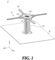
- FIG. 1 is a combined perspective view of a radiation element structure according to an embodiment of the present disclosure.
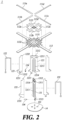
- FIG. 2 is an exploded perspective view of a radiation element structure according to an embodiment of the present disclosure.
- a radiation element structure of the present disclosure may include all or part of a radiation unit 11, a first balun unit 12, and a second balun unit 13.
- an antenna of the present disclosure may include all or part of the radiation element structure 1 and a reflector 14.
- the radiation unit 11 may include all or part of a plurality of radiation arms 111, a plurality of sub-grounds 112, and a radiation plate 113.
- the plurality of radiation arms 111 may be arranged on one surface of the radiation plate 113 in a four-sided symmetrical structure.
- the plurality of radiation arms 111 may be arranged at predetermined intervals on the same plane and may be arranged in an overall '+' shape. For example, based on a first radiation arm 111a, a second radiation arm 111b may be arranged perpendicularly to the first radiation arm 111a, a third radiation arm 111c may be arranged perpendicularly to the second radiation arm 111b, and a fourth radiation arm 111d may be arranged perpendicularly to the third radiation arm 111c.
- the first radiation arm 111a and the third radiation arm 111c may be arranged in a line at a predetermined interval.
- the first radiation arm 111a and the third radiation arm 111c may be arranged in a first direction.
- the first direction may be a direction parallel to the Y-axis of FIG. 1 .
- the second radiation arm 111b and the fourth radiation arm 111d may be arranged in a line at a predetermined interval.
- the second radiation arm 111b and the fourth radiation arm 111d may be arranged in a second direction perpendicular to the first direction.
- the second direction may be a direction parallel to the X-axis of FIG. 1 .
- the plurality of sub-grounds 112 may be arranged on one side of the radiation plate 113, and may each be disposed between adjacent radiation arms 111.
- a first sub-ground 112a may be disposed between the first radiation arm 111a and the second radiation arm 111b.
- a second sub-ground 112b may be disposed between the second radiation arm 111b and the third radiation arm 111c.
- a third sub-ground 112c may be disposed between the third radiation arm 111c and the fourth radiation arm 111d.
- a fourth sub-ground 112d may be disposed between the fourth radiation arm 111d and the first radiation arm 111a.
- the plurality of sub-grounds 112 may have a right-angled triangle shape and may be arranged so that right-angled portions are gathered at the center of the radiation plate 113.
- a first insertion groove 1121 may be formed at each right-angled end of the plurality of sub-grounds 112.
- a balun unit 12, 13 to be described later may be inserted into the first insertion groove 1121.
- Each sub-ground 112 may have the shape of a right triangle, but at least part of the hypotenuse facing the right angle may be recessed.
- each sub-ground 112 may have a staircase shape, but the shape of each sub-ground 112 of the present disclosure is not limited thereto. By having at least part of each sub-ground 112 recessed, it is possible to reduce the influence of the radiation unit 11 on other bands.
- the radiation plate 113 may have a shape corresponding to the plurality of radiation arms 111 and the plurality of sub-grounds 112.
- the radiation plate 113 may be formed in a four-sided symmetrical structure and may be formed so that the plurality of radiation arms 111 and the plurality of sub-grounds 112 are all arranged on one side.
- the radiation plate 113 may be formed of a dielectric material, for example, plastic.
- the radiation plate 113 may include a plurality of first grooves 1132. By forming the plurality of first grooves 1132 in the radiation plate 113, it is possible to reduce the weight of the radiation unit 11. In addition, by adjusting the dielectric constant of the radiating portion 11, it is possible to adjust radiation characteristics of the radiation element structure 1.
- By forming the radiation plate 113 of a plastic material it is possible for the radiation element structure 1 of the present disclosure to ensure a high degree of freedom in materials and shapes. For example, unlike an element formed of a conventional PCB (e.g., FR4 material), the dielectric material may be removed even in areas where metal (e.g., radiation arms) is present.
- the radiation plate 113 may include a plurality of second insertion grooves 1131.
- the second insertion grooves 1131 may be formed in the center of the radiation plate 113.
- the second insertion grooves 1131 may be formed to correspond to the first insertion grooves 1121 of the sub-grounds 112 so that the balun unit 12, 13, which will be described later, can be inserted into the second insertion grooves 1131.
- the balun unit 12, 13 may include a first balun unit 12 and a second balun unit 13. Common characteristics related to the first balun unit 12 and the second balun unit 13 will be described together.
- the balun unit 12, 13 may connect the radiation unit 11 to the reflector 14.
- the balun unit 12, 13 may be connected perpendicularly to the radiation unit 11.
- the balun unit 12, 13 may be connected perpendicularly to the reflector 14.
- the balun unit 12, 13 may be formed of a dielectric material, for example, plastic.
- the balun unit 12, 13 may include a plurality of second grooves 1211 and 1311. By forming the plurality of second grooves 1211 and 1311 in the balun unit 12, 13, it is possible to reduce the weight of the balun units 12 and 13.
- the dielectric constant of the balun unit 12, 13, it is possible to adjust the frequency characteristics of the radiation element structure 1. For example, the required radiation or reception frequency may be adjusted.
- the balun unit 12, 13 of plastic it is possible for the radiation element structure 1 of the present disclosure to ensure a high degree of freedom in materials and shapes.
- the dielectric material may be removed even in areas where metal (e.g., feed lines) is present.
- the balun unit 12, 13 may include a balun body 121, 131, a feed line 122, 132, a ground 123, 133, and a connect port 124, 134.
- the balun body 121, 131 may include a second groove 1211, 1311, a first protrusion 1212, 1312, a connection part 1213, 1313, and a slit 1214, 1314.
- the balun body 121, 131 is formed of plastic, and the balun body 121, 131, the second groove 1211, 1311, the first protrusion 1212, 1312, the connection part 1213, 1313, and the slit 1214, 1314 may be integrally formed.
- the first protrusion 1212, 1312 may be formed at one end of the balun body 121, 131 in the Z-axis direction (towards the radiation unit).
- the first protrusion 1212, 1312 may be inserted into the second insertion groove 1131 of the radiation plate 113 and the first insertion groove 1121 of the sub-ground 112.
- the first protrusion 1212, 1312 may be sequentially inserted into the second insertion groove 1131 and the first insertion groove 1121 to connect the balun unit 12, 13 and the radiation unit 11.
- connection part 1213, 1313 may be formed at the other end of the balun body 121, 131 in the Z-axis direction (toward the reflector).
- the connection part 1213, 1313 may be inserted into the third insertion groove 141 of the reflector 14.
- the connection part 1213, 1313 may be inserted into the third insertion groove 141 to connect the balun unit 12, 13 and the reflector 14.
- the first balun unit 12 may include a first balun body 121, and the first balun body 121 may include a first slit 1214.
- the second balun unit 13 includes a second balun body 131, and the second balun body 131 may include a second slit 1314.
- the first balun unit 12 and the second balun unit 13 may be coupled perpendicularly to each other.
- the first slit 1214 may be formed at a lower end of the first balun unit 12 (towards the reflector), and the second slit 1314 may be formed at an upper end of the second balun unit 13 (towards the radiation unit). As the first slit 1214 is inserted into the second slit 1314, the first balun unit 12 and the second balun unit 13 may be coupled perpendicularly to each other.
- the first balun unit 12 may be coupled perpendicularly to the radiation unit 11, so that a width direction of the first balun unit 12 faces the third direction.
- the third direction is a direction parallel to a line that bisects the angle between the first radiation arm 111a and the second radiation arm 111b.
- the second balun unit 13 may be coupled perpendicularly to the radiation unit 11, so that a width direction of the second balun unit 13 faces the fourth direction which is perpendicular to the third direction.
- the fourth direction is a direction parallel to a line that bisects the angle between the second radiation arm 111b and the third radiation arm 111c.
- the present disclosure is not limited thereto, and the width directions of the first balun unit 12 and the second balun unit 13 may be at a predetermined angle relative to a longitudinal direction of the radiation arms 111.
- the feed line 122, 132 may be disposed on an upper surface of the balun body 121, 131.
- the upper surface refers to a direction on which the feed line 122, 132 is disposed among the two surfaces of the balun body 121, 131.
- the feed line 122, 132 may be configured to feed a plurality of radiation arms 111.
- the feed line 122, 132 may feed the plurality of radiation arms 111 in a coupling method.
- the present disclosure is not limited thereto, and the feed line 122, 132 may be directly connected to the plurality of radiation arms 111.
- the plurality of radiation arms 111 may transmit and receive signals or receive power using the feed line 122, 132.
- the first balun unit 12 may include a first feed line 122
- the second balun unit 13 may include a second feed line 132.
- the first feed line 122 may be formed in a ' ' shape.
- the first feed line 122 may extend in a longitudinal direction of the first balun unit 12 (Z-axis direction), then be bent in the third direction, and then bent again in the longitudinal direction of the first balun unit 12 (Z-axis direction).
- the second feed line 132 may be formed in a ' ' shape.
- the second feed line 132 may extend in a longitudinal direction of the second balun unit 13 (Z-axis direction), then be bent in the fourth direction, and then bent again in the longitudinal direction of the second balun unit 13 (Z-axis direction). That is, the first feed line 122 and the second feed line 132 may intersect each other perpendicularly.
- the first feed line 122 and the second feed line 132 may receive feed signals from separate signal sources, respectively.
- the first feed line 122 may receive a feed signal using a first connection port 124
- the second feed line 132 may receive a feed signal using a second connection port 134.
- the feed into the first feed line 122 and the second feed line 132 may be provided using a coaxial cable.
- the connection port 124, 134 may be connected to an RF circuit equipped with a filter, a power amplifier, a power supply unit, etc.
- the first feed line 122 may collectively feed the first radiation arm 111a and the second radiation arm 111b, and may also collectively feed the third radiation arm 111c and the fourth radiation arm 111d.
- the second feed line 132 extends along the fourth direction, the second feed line 132 may collectively feed the second radiation arm 111b and the third radiation arm 111c, and may also collectively feed the first radiation arm 111a and the fourth radiation arm 111d.
- the first feed line 122 and the second feed line 132 may feed the plurality of radiation arms 111 in a capacitance coupling method.
- the ground 123, 133 may include a bent part 1231, 1331 and a second protrusion 1232, 1332.
- the second protrusion 1232, 1332 may be formed at one end (toward the radiation unit) of the ground 123, 133 in the Z-axis direction.
- the second protrusion 1232, 1332 may be inserted into the second insertion grooves 1131 of the radiation plate 113 and the first insertion grooves 1121 of the sub-grounds 112.
- the second protrusion 1212, 1312 may be sequentially inserted into the second insertion grooves 1131 and the first insertion grooves 1121 to connect the balun unit 12, 13 and the radiation unit 11.
- the ground 123, 133 may be soldered to the sub-ground 112.
- An end of the second protrusion 1212, 1312 is soldered to the sub-ground 112, thereby connecting the balun unit 12, 13 and the radiation unit 11.
- the bent part 1231, 1331 may be formed at the other end (toward the reflector) of the ground 123, 133 in the Z-axis direction.
- the bent part 1231, 1331 may be formed by bending the other end of the grounds 123, 133.
- the bent parts 1231, 1331 may be bent to be parallel to the reflector 14.
- the balun unit 12, 13 and the reflector 14 may be easily connected in the radiation element structure 1 of the present disclosure.
- the balun unit 12, 13 and the reflector 14 may be connected without any additional component, unlike an element formed of a conventional PCB. Therefore, the radiation element structure 1 of the present disclosure increases structural stability by reducing the number of connection points in a manufacturing process and facilitates mass production.
- the balun unit 12, 13 and the reflector 14 may be connected in a direct connection method and/or a coupling connection methods.
- FIG. 3 is a top view of a radiation element structure according to an embodiment of the present disclosure.
- a plurality of radiation arms 111 may each include a step 1111. At least a portion of each radiation arm 111 along a longitudinal direction may include the step 1111 with a non-uniform width.
- the longitudinal direction of each radiation arm 111 refers to a direction from the center of a radiation plate 113 toward an end portion 1112 of a corresponding radiation arm 111. That is, each radiation arm 111 may have a multi-stage structure where a width (in a direction perpendicular to the longitudinal direction) is not uniform. As each radiation arm 111 is formed with a multi-stage structure, it is possible to reduce the influence of the radiation unit 11 on other frequency bands.
- each radiation arm 111 may be 1/4 of the wavelength (lambda) of the operating frequency.
- the total length of two radiation arms located on the same axis may be 1/2 lambda.
- a sum of the lengths of the first radiation arm 111a and the third radiation arm 111c located in the first direction may be 1/2 lambda
- a sum of the lengths of the second radiation arm 111b and the fourth radiation arm 111d located in the second direction may be 1/2 lambda.
- FIG. 4 is an enlarged view of an end portion of the radiation arm of a radiation element structure according to an embodiment of the present disclosure.
- each end portion 1112 of a plurality of radiation arms 111 may be bent.
- Each end portion 1112 may be bent in a direction parallel to the Z-axis.
- Each end portion 1112 may be bent in a direction parallel to the Z-axis, but may be bent in a direction toward the reflector 14.
- the bending direction and angle of the end portion 1112 are not limited thereto and may be set in various ways as needed.
- the end portion 1112 of each radiation arm 111 is bent, the length of each radiation arm 111 is reduced, and consequently, it is possible to reduce the influence of the radiation unit 11 on other frequency bands.
- each radiation arm 111 by bending the end portion 1112 of each radiation arm 111, it is possible to three-dimensionally implement the shape of the radiation unit 11 without any additional component, unlike an element formed of a conventional PCB.
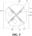
- FIG. 5 is a cross-sectional view of a radiation element structure according to an embodiment of the present disclosure cut in a plane perpendicular to the Z-axis.
- FIG. 6 is an enlarged view of a balun unit of the radiation element structure according to an embodiment of the present disclosure.
- a ground 123, 133 of a balun unit 12, 13 may include a first ground 123a, 133a and a second ground 123b, 133b.
- the first ground 123a, 133a and the second ground 123b, 133b may all be arranged at a lower surface of the balun unit 12, 13.
- the lower surface refers to a surface of the balun body 121, 131, where a feed line 122, 132 is not disposed.
- the first ground 123a, 133a may be disposed at the lower surface of the balun unit 12, 13, with a bent part 1231, 1331 facing towards an upper surface of the balun unit 12, 13.
- the second ground 123b, 133b may be disposed at the lower surface of the balun unit 12, 13, with the bent part 1231, 1331 facing toward the lower surface of the balun unit 12, 13.
- Each bent part 1231 of a first balun unit 12 may be disposed parallel to a third direction, but may be disposed to face opposite directions.
- Each bent part 1331 of a second balun unit 13 may be disposed parallel to a fourth direction, but may be disposed to face opposite directions. Therefore, structural stability may be increased when connecting the balun unit 12, 13 and the reflector 14.
Landscapes
- Physics & Mathematics (AREA)
- Electromagnetism (AREA)
- Engineering & Computer Science (AREA)
- Computer Networks & Wireless Communication (AREA)
- Aerials With Secondary Devices (AREA)
- Variable-Direction Aerials And Aerial Arrays (AREA)
Abstract
Description
- The present disclosure relates to a radiation element structure.
- The content described in this section simply provides background information for the present disclosure and does not constitute prior art.
- Antennas, which are widely used in base stations and repeaters of mobile communication systems, are being researched to meet the demands for miniaturization and being light in weight. Multi-band antennas that can cover multiple bands and provide various services are becoming popular.
- Massive MIMO (Multiple Input Multiple Output) technology is a technology that dramatically increases data transmission capacity by using multiple antennas. It is a spatial multiplexing technique where the transmitter uses each transmitting antenna to send different data, and the receiver uses appropriate signal processing to distinguish the transmitted data. Therefore, by simultaneously increasing the number of tranceiving antennas, the channel capacity increases, allowing more data to be transmitted.
- The problem with using a multi-band antenna is that the high-band and low-band radiators affect each other, which degrades the radiation characteristics of the antenna.
- Additionally, to realize a dual-polarized antenna capable of reducing the mutual influence of multiple radiating elements in a multi-band antenna, it is necessary to design the antenna considering the radiation performance, radiation characteristics, shape, size, manufacturing method, and ease of design of the radiating elements.
- A radiation element structure according to an embodiment can minimize the influence of a plurality of radiation elements on one another in a multi-band antenna by minimizing the shape and volume of a radiation element.
- The radiation element structure according to an embodiment can reduce the number of connection points in an antenna manufacturing process by using a plastic material.
- The problems to be solved by the present disclosure are not limited to the aforementioned problems, and other problems not mentioned can be clearly understood by those skilled in the art from the description below.
- According to an embodiment of the present disclosure, there is provided a radiation element structure disposed on a reflector, the structure including: a radiation unit comprising a dielectric portion formed of a plastic material and first to fourth radiating arms disposed on one side of the dielectric portion in a four-sided symmetrical structure; and a plurality of balun units each comprising a balun body connecting the reflector and the radiation unit, a feed line disposed on an upper surface of the balun body to feed the radiation unit, and a ground disposed on a lower surface of the balun body.
- According to one embodiment, the radiating element structure has the effect of stabilizing radiation characteristics of an antenna and facilitating the design of the antenna by minimizing the shape and volume of a radiating element.
- According to one embodiment, the radiating element structure has the effect of increasing the structural stability of the antenna and enabling mass production of the antenna by reducing the number of connection points in a manufacturing process using a plastic material.
-
-
FIG. 1 is a combined perspective view of a radiation element structure according to an embodiment of the present disclosure. -
FIG. 2 is an exploded perspective view of a radiation element structure according to an embodiment of the present disclosure. -
FIG. 3 is a top view of a radiation element structure according to an embodiment of the present disclosure. -
FIG. 4 is an enlarged view of an end portion of the radiation arm of a radiation element structure according to an embodiment of the present disclosure. -
FIG. 5 is a cross-sectional view of a radiation element structure according to an embodiment of the present disclosure cut in a plane perpendicular to the Z-axis. -
FIG. 6 is an enlarged view of a balun unit of the radiation element structure according to an embodiment of the present disclosure. - Hereinafter, some embodiments of the present disclosure will be described in detail through illustrative drawings. When adding reference numerals to the components in each drawing, it should be noted that the same components are given the same numerals as much as possible, even if the components are shown in different drawings. Additionally, in describing the present disclosure, if it is determined that a detailed description of known functions and components unnecessarily obscure the gist of the present disclosure, the detailed description thereof will be omitted.
- In describing the components of the embodiment according to the present disclosure, various terms such as first, second, i), ii), (a), (b), etc., may be used. These terms are used solely for the purpose of differentiating one component from the other, not to imply or suggest the substances, or the order or sequence of the components. Throughout the specification, when a part "includes" or "comprises" a component, the part is meant to further include, not exclude, other components unless there is a particular description contrary thereto.
-
FIG. 1 is a combined perspective view of a radiation element structure according to an embodiment of the present disclosure. -
FIG. 2 is an exploded perspective view of a radiation element structure according to an embodiment of the present disclosure. - Referring to
FIGS. 1 and2 , a radiation element structure of the present disclosure may include all or part of aradiation unit 11, afirst balun unit 12, and asecond balun unit 13. In addition, an antenna of the present disclosure may include all or part of theradiation element structure 1 and areflector 14. - The
radiation unit 11 may include all or part of a plurality ofradiation arms 111, a plurality ofsub-grounds 112, and aradiation plate 113. - The plurality of
radiation arms 111 may be arranged on one surface of theradiation plate 113 in a four-sided symmetrical structure. The plurality ofradiation arms 111 may be arranged at predetermined intervals on the same plane and may be arranged in an overall '+' shape. For example, based on afirst radiation arm 111a, asecond radiation arm 111b may be arranged perpendicularly to thefirst radiation arm 111a, athird radiation arm 111c may be arranged perpendicularly to thesecond radiation arm 111b, and a fourth radiation arm 111d may be arranged perpendicularly to thethird radiation arm 111c. - The
first radiation arm 111a and thethird radiation arm 111c may be arranged in a line at a predetermined interval. Thefirst radiation arm 111a and thethird radiation arm 111c may be arranged in a first direction. At this point, the first direction may be a direction parallel to the Y-axis ofFIG. 1 . Thesecond radiation arm 111b and the fourth radiation arm 111d may be arranged in a line at a predetermined interval. Thesecond radiation arm 111b and the fourth radiation arm 111d may be arranged in a second direction perpendicular to the first direction. At this point, the second direction may be a direction parallel to the X-axis ofFIG. 1 . - The plurality of
sub-grounds 112 may be arranged on one side of theradiation plate 113, and may each be disposed betweenadjacent radiation arms 111. For example, afirst sub-ground 112a may be disposed between thefirst radiation arm 111a and thesecond radiation arm 111b. A second sub-ground 112b may be disposed between thesecond radiation arm 111b and thethird radiation arm 111c. Athird sub-ground 112c may be disposed between thethird radiation arm 111c and the fourth radiation arm 111d. Afourth sub-ground 112d may be disposed between the fourth radiation arm 111d and thefirst radiation arm 111a. - The plurality of
sub-grounds 112 may have a right-angled triangle shape and may be arranged so that right-angled portions are gathered at the center of theradiation plate 113. Afirst insertion groove 1121 may be formed at each right-angled end of the plurality ofsub-grounds 112. Abalun unit first insertion groove 1121. - Each
sub-ground 112 may have the shape of a right triangle, but at least part of the hypotenuse facing the right angle may be recessed. For example, eachsub-ground 112 may have a staircase shape, but the shape of eachsub-ground 112 of the present disclosure is not limited thereto. By having at least part of eachsub-ground 112 recessed, it is possible to reduce the influence of theradiation unit 11 on other bands. - The
radiation plate 113 may have a shape corresponding to the plurality ofradiation arms 111 and the plurality ofsub-grounds 112. Theradiation plate 113 may be formed in a four-sided symmetrical structure and may be formed so that the plurality ofradiation arms 111 and the plurality ofsub-grounds 112 are all arranged on one side. - The
radiation plate 113 may be formed of a dielectric material, for example, plastic. Theradiation plate 113 may include a plurality offirst grooves 1132. By forming the plurality offirst grooves 1132 in theradiation plate 113, it is possible to reduce the weight of theradiation unit 11. In addition, by adjusting the dielectric constant of theradiating portion 11, it is possible to adjust radiation characteristics of theradiation element structure 1. By forming theradiation plate 113 of a plastic material, it is possible for theradiation element structure 1 of the present disclosure to ensure a high degree of freedom in materials and shapes. For example, unlike an element formed of a conventional PCB (e.g., FR4 material), the dielectric material may be removed even in areas where metal (e.g., radiation arms) is present. - The
radiation plate 113 may include a plurality ofsecond insertion grooves 1131. Thesecond insertion grooves 1131 may be formed in the center of theradiation plate 113. Thesecond insertion grooves 1131 may be formed to correspond to thefirst insertion grooves 1121 of the sub-grounds 112 so that thebalun unit second insertion grooves 1131. - The
balun unit first balun unit 12 and asecond balun unit 13. Common characteristics related to thefirst balun unit 12 and thesecond balun unit 13 will be described together. Thebalun unit radiation unit 11 to thereflector 14. Thebalun unit radiation unit 11. Thebalun unit reflector 14. - The
balun unit balun unit second grooves second grooves balun unit balun units balun unit radiation element structure 1. For example, the required radiation or reception frequency may be adjusted. By forming thebalun unit radiation element structure 1 of the present disclosure to ensure a high degree of freedom in materials and shapes. For example, unlike an element formed of a conventional PCB, the dielectric material may be removed even in areas where metal (e.g., feed lines) is present. - The
balun unit balun body feed line ground connect port - The
balun body second groove first protrusion connection part slit balun body balun body second groove first protrusion connection part slit - The
first protrusion balun body first protrusion second insertion groove 1131 of theradiation plate 113 and thefirst insertion groove 1121 of the sub-ground 112. Thefirst protrusion second insertion groove 1131 and thefirst insertion groove 1121 to connect thebalun unit radiation unit 11. - The
connection part balun body connection part third insertion groove 141 of thereflector 14. Theconnection part third insertion groove 141 to connect thebalun unit reflector 14. - The
first balun unit 12 may include afirst balun body 121, and thefirst balun body 121 may include afirst slit 1214. Thesecond balun unit 13 includes asecond balun body 131, and thesecond balun body 131 may include asecond slit 1314. Thefirst balun unit 12 and thesecond balun unit 13 may be coupled perpendicularly to each other. Thefirst slit 1214 may be formed at a lower end of the first balun unit 12 (towards the reflector), and thesecond slit 1314 may be formed at an upper end of the second balun unit 13 (towards the radiation unit). As thefirst slit 1214 is inserted into thesecond slit 1314, thefirst balun unit 12 and thesecond balun unit 13 may be coupled perpendicularly to each other. - The
first balun unit 12 may be coupled perpendicularly to theradiation unit 11, so that a width direction of thefirst balun unit 12 faces the third direction. Here, the third direction is a direction parallel to a line that bisects the angle between thefirst radiation arm 111a and thesecond radiation arm 111b. - The
second balun unit 13 may be coupled perpendicularly to theradiation unit 11, so that a width direction of thesecond balun unit 13 faces the fourth direction which is perpendicular to the third direction. Here, the fourth direction is a direction parallel to a line that bisects the angle between thesecond radiation arm 111b and thethird radiation arm 111c. However, the present disclosure is not limited thereto, and the width directions of thefirst balun unit 12 and thesecond balun unit 13 may be at a predetermined angle relative to a longitudinal direction of theradiation arms 111. - The
feed line balun body feed line balun body balun body feed line radiation arms 111. Thefeed line radiation arms 111 in a coupling method. However, the present disclosure is not limited thereto, and thefeed line radiation arms 111. The plurality ofradiation arms 111 may transmit and receive signals or receive power using thefeed line - The
first balun unit 12 may include afirst feed line 122, and thesecond balun unit 13 may include asecond feed line 132. Thefirst feed line 122 may be formed in a '' shape. For example, the
first feed line 122 may extend in a longitudinal direction of the first balun unit 12 (Z-axis direction), then be bent in the third direction, and then bent again in the longitudinal direction of the first balun unit 12 (Z-axis direction). Thesecond feed line 132 may be formed in a '' shape. For example, the
second feed line 132 may extend in a longitudinal direction of the second balun unit 13 (Z-axis direction), then be bent in the fourth direction, and then bent again in the longitudinal direction of the second balun unit 13 (Z-axis direction). That is, thefirst feed line 122 and thesecond feed line 132 may intersect each other perpendicularly. - The
first feed line 122 and thesecond feed line 132 may receive feed signals from separate signal sources, respectively. Thefirst feed line 122 may receive a feed signal using afirst connection port 124, and thesecond feed line 132 may receive a feed signal using asecond connection port 134. The feed into thefirst feed line 122 and thesecond feed line 132 may be provided using a coaxial cable. Theconnection port - Since the
first feed line 122 extends along the third direction, thefirst feed line 122 may collectively feed thefirst radiation arm 111a and thesecond radiation arm 111b, and may also collectively feed thethird radiation arm 111c and the fourth radiation arm 111d. Since thesecond feed line 132 extends along the fourth direction, thesecond feed line 132 may collectively feed thesecond radiation arm 111b and thethird radiation arm 111c, and may also collectively feed thefirst radiation arm 111a and the fourth radiation arm 111d. Thefirst feed line 122 and thesecond feed line 132 may feed the plurality ofradiation arms 111 in a capacitance coupling method. - The
ground bent part second protrusion second protrusion ground second protrusion second insertion grooves 1131 of theradiation plate 113 and thefirst insertion grooves 1121 of the sub-grounds 112. Thesecond protrusion second insertion grooves 1131 and thefirst insertion grooves 1121 to connect thebalun unit radiation unit 11. - The
ground second protrusion balun unit radiation unit 11. - The
bent part ground bent part grounds bent parts reflector 14. - With the
bent part ground reflector 14, thebalun unit reflector 14 may be easily connected in theradiation element structure 1 of the present disclosure. By using thebent part balun unit reflector 14 may be connected without any additional component, unlike an element formed of a conventional PCB. Therefore, theradiation element structure 1 of the present disclosure increases structural stability by reducing the number of connection points in a manufacturing process and facilitates mass production. Thebalun unit reflector 14 may be connected in a direct connection method and/or a coupling connection methods. -
FIG. 3 is a top view of a radiation element structure according to an embodiment of the present disclosure. - Referring to
FIG. 3 , a plurality ofradiation arms 111 may each include astep 1111. At least a portion of eachradiation arm 111 along a longitudinal direction may include thestep 1111 with a non-uniform width. Here, the longitudinal direction of eachradiation arm 111 refers to a direction from the center of aradiation plate 113 toward anend portion 1112 of acorresponding radiation arm 111. That is, eachradiation arm 111 may have a multi-stage structure where a width (in a direction perpendicular to the longitudinal direction) is not uniform. As eachradiation arm 111 is formed with a multi-stage structure, it is possible to reduce the influence of theradiation unit 11 on other frequency bands. - The length of each
radiation arm 111 may be 1/4 of the wavelength (lambda) of the operating frequency. Thus, the total length of two radiation arms located on the same axis may be 1/2 lambda. For example, a sum of the lengths of thefirst radiation arm 111a and thethird radiation arm 111c located in the first direction may be 1/2 lambda, and a sum of the lengths of thesecond radiation arm 111b and the fourth radiation arm 111d located in the second direction may be 1/2 lambda. -
FIG. 4 is an enlarged view of an end portion of the radiation arm of a radiation element structure according to an embodiment of the present disclosure. - Referring to
FIG. 4 , eachend portion 1112 of a plurality ofradiation arms 111 may be bent. Eachend portion 1112 may be bent in a direction parallel to the Z-axis. Eachend portion 1112 may be bent in a direction parallel to the Z-axis, but may be bent in a direction toward thereflector 14. However, the bending direction and angle of theend portion 1112 are not limited thereto and may be set in various ways as needed. As theend portion 1112 of eachradiation arm 111 is bent, the length of eachradiation arm 111 is reduced, and consequently, it is possible to reduce the influence of theradiation unit 11 on other frequency bands. - In addition, by bending the
end portion 1112 of eachradiation arm 111, it is possible to three-dimensionally implement the shape of theradiation unit 11 without any additional component, unlike an element formed of a conventional PCB. -
FIG. 5 is a cross-sectional view of a radiation element structure according to an embodiment of the present disclosure cut in a plane perpendicular to the Z-axis. -
FIG. 6 is an enlarged view of a balun unit of the radiation element structure according to an embodiment of the present disclosure. - Referring to
FIGS. 5 and6 , aground balun unit first ground second ground 123b, 133b. Thefirst ground second ground 123b, 133b may all be arranged at a lower surface of thebalun unit balun body feed line - The
first ground balun unit bent part balun unit second ground 123b, 133b may be disposed at the lower surface of thebalun unit bent part balun unit - Each
bent part 1231 of afirst balun unit 12 may be disposed parallel to a third direction, but may be disposed to face opposite directions. Eachbent part 1331 of asecond balun unit 13 may be disposed parallel to a fourth direction, but may be disposed to face opposite directions. Therefore, structural stability may be increased when connecting thebalun unit reflector 14. - The above description is merely illustrative of the technical concepts of the present embodiment, and those skilled in the art to which the present embodiment pertains will appreciate that various modifications, changes, and alterations can be made without departing from the essential characteristics of the present embodiment. Accordingly, the embodiments are illustrative and not intended to limit the technical ideas of the present disclosure, and the scope of the technical ideas of the present disclosure is not limited by these embodiments. The scope of the present disclosure shall be construed in accordance with the following claims, and all technical ideas within the scope of the equivalents shall be construed to be included within the scope of the present disclosure.
-
- 1: radiation element structure
- 11: radiation unit
- 12: first balun unit
- 13: second balun unit
- 14: reflector
- This application claims the benefit of
Korean Patent Application No. 10-2022-0042829, filed in Korea on April 6, 2022
Claims (20)
- A radiation element structure disposed on a reflector, the structure comprising:a radiation unit comprising a dielectric portion formed of a plastic material and first to fourth radiating arms disposed on one side of the dielectric portion in a four-sided symmetrical structure; anda plurality of balun units each comprising a balun body connecting the reflector and the radiation unit, a feed line disposed on an upper surface of the balun body to feed the radiation unit, and a ground disposed on a lower surface of the balun body.
- The radiation element structure of claim 1,wherein the first to fourth radiation arms are arranged on the same plane,wherein the second radiation arm is perpendicular to the first radiation arm,wherein the third radiation arm is perpendicular to the second radiation arm, andwherein the fourth radiation arm is disposed perpendicular to the third radiation arm.
- The radiation element structure of claim 1, wherein one end of each of the first to fourth radiation arms is bent toward the reflector.
- The radiation element structure of claim 1, wherein, in the first to fourth radiation arms, at least a portion along a longitudinal direction is formed in a multi-stage structure.
- The radiation element structure of claim 1,wherein the radiation unit further comprises a plurality of sub-grounds each disposed between adjacent radiation arms, andwherein the sub-grounds are each connected to the ground.
- The radiation element structure of claim 5, wherein the sub-grounds are each formed in a step shape.
- The radiation element structure of claim 1, wherein the balun unit comprises a first balun unit having a first feed line, and a second balun unit perpendicularly intersecting the first balun unit and having a second feed line.
- The radiation element structure of claim 7, wherein a width direction of the first balun unit and the second balun unit forms a predetermined angle relative to the longitudinal direction of the radiation arms.
- The radiation element structure of claim 7, wherein the first feed line and the second feed line receive feeding signals from different signal sources.
- The radiation element structure of claim 7, wherein the first feed line collectively feed the first radiation arm and the second radiation arm disposed perpendicularly to the first radiation arm.
- The radiation element structure of claim 7, wherein the second feed line collectively feed the second radiation arm and the third radiation arm disposed perpendicularly to the second radiation arm.
- The radiation element structure of claim 5, wherein the ground comprises a protrusion protruding in Z-axis direction at one end, and a bent part bent to be parallel to the reflector at the other end.
- The radiation element structure of claim 12, wherein the protrusion is soldered to the sub-ground by soldering.
- The radiation element structure of claim 12, wherein the bending part is coupled to with the reflector.
- The radiation element structure of claim 1, wherein the dielectric portion comprises one or more grooves arranged at predetermined intervals.
- The radiation element structure of claim 1, wherein the balun body is formed of a plastic material and comprises one or more grooves.
- The radiation element structure of claim 1, wherein the radiating part and the balun unit are perpendicularly coupled to each other.
- An antenna comprising:a reflector;a radiation unit comprising a dielectric portion formed of a plastic material, first to fourth radiating arms disposed on one surface of the dielectric portion, and a plurality of sub-grounds respectively disposed between adjacent radiating arms in a four-sided symmetrical structure; anda plurality of balun units each comprising a balun body connecting the reflector and the radiation unit, a feed line disposed on an upper surface of the balun body to feed the radiation unit, and a ground disposed on a lower surface of the balun body and connected to the sub-ground.
- The antenna of claim 18, wherein one end of each of the first to fourth radiation arm is bent toward the reflector.
- The antenna of claim 18, wherein the balun unit comprises a first balun unit having a first feed line, and a second balun unit perpendicularly intersecting the first balun unit and having a second feed line.
Applications Claiming Priority (2)
| Application Number | Priority Date | Filing Date | Title |
|---|---|---|---|
| KR1020220042829A KR20230144148A (en) | 2022-04-06 | 2022-04-06 | Radiation Element Structure |
| PCT/KR2023/004108 WO2023195674A1 (en) | 2022-04-06 | 2023-03-28 | Radiation element structure |
Publications (2)
| Publication Number | Publication Date |
|---|---|
| EP4507123A1 true EP4507123A1 (en) | 2025-02-12 |
| EP4507123A4 EP4507123A4 (en) | 2026-04-08 |
Family
ID=88243222
Family Applications (1)
| Application Number | Title | Priority Date | Filing Date |
|---|---|---|---|
| EP23784902.1A Pending EP4507123A4 (en) | 2022-04-06 | 2023-03-28 | RADIATION ELEMENT STRUCTURE |
Country Status (6)
| Country | Link |
|---|---|
| US (1) | US20250023237A1 (en) |
| EP (1) | EP4507123A4 (en) |
| JP (1) | JP7817436B2 (en) |
| KR (1) | KR20230144148A (en) |
| CN (1) | CN118843989A (en) |
| WO (1) | WO2023195674A1 (en) |
Family Cites Families (13)
| Publication number | Priority date | Publication date | Assignee | Title |
|---|---|---|---|---|
| JP2002084133A (en) | 2000-09-08 | 2002-03-22 | Mitsubishi Electric Corp | Antenna device |
| KR100865749B1 (en) * | 2008-04-02 | 2008-10-28 | 주식회사 감마누 | Wideband Bipolar Planar Dipole Antenna |
| JP5309193B2 (en) * | 2011-07-19 | 2013-10-09 | 電気興業株式会社 | Polarization diversity array antenna device |
| EP2831952A1 (en) * | 2012-03-26 | 2015-02-04 | Galtronics Corporation Ltd. | Isolation structures for dual-polarized antennas |
| CN104821427B (en) * | 2015-04-22 | 2018-02-23 | 董玉良 | INDIRECT COUPLING antenna element |
| US20170062952A1 (en) * | 2015-09-02 | 2017-03-02 | Ace Antenna Company Inc. | Dual band, multi column antenna array for wireless network |
| CN107134639B (en) | 2017-05-26 | 2019-08-20 | 华南理工大学 | Broadband dual-frequency base-station antenna array is isolated in high alien frequencies |
| KR102125803B1 (en) * | 2019-05-10 | 2020-06-23 | 주식회사 에이스테크놀로지 | Base Station Antenna Radiator for Rejecting Unwanted Resonance |
| CN110429374B (en) * | 2019-07-29 | 2024-04-05 | 华南理工大学 | Broadband dual-polarized filtering base station antenna unit, base station antenna array and communication equipment |
| CN111146576A (en) | 2020-03-02 | 2020-05-12 | 深圳信息通信研究院 | A small dual-polarized broadband high-isolation antenna |
| KR102958306B1 (en) | 2020-09-28 | 2026-04-29 | 삼성전자주식회사 | Metalic mold system with tapping unit |
| CN112635988B (en) * | 2020-12-17 | 2024-02-09 | 立讯精密工业(滁州)有限公司 | Antenna element unit |
| CN113131197B (en) * | 2021-03-12 | 2022-05-03 | 西安电子科技大学 | Dual-polarized antenna unit and base station antenna |
-
2022
- 2022-04-06 KR KR1020220042829A patent/KR20230144148A/en active Pending
-
2023
- 2023-03-28 EP EP23784902.1A patent/EP4507123A4/en active Pending
- 2023-03-28 JP JP2024556496A patent/JP7817436B2/en active Active
- 2023-03-28 WO PCT/KR2023/004108 patent/WO2023195674A1/en not_active Ceased
- 2023-03-28 CN CN202380029662.9A patent/CN118843989A/en active Pending
-
2024
- 2024-09-27 US US18/900,594 patent/US20250023237A1/en active Pending
Also Published As
| Publication number | Publication date |
|---|---|
| CN118843989A (en) | 2024-10-25 |
| WO2023195674A1 (en) | 2023-10-12 |
| JP7817436B2 (en) | 2026-02-18 |
| JP2025510796A (en) | 2025-04-15 |
| US20250023237A1 (en) | 2025-01-16 |
| EP4507123A4 (en) | 2026-04-08 |
| KR20230144148A (en) | 2023-10-16 |
Similar Documents
| Publication | Publication Date | Title |
|---|---|---|
| US11095040B2 (en) | Antenna and mimo antenna | |
| US20060119532A1 (en) | Circular polarized helical radiation element and its array antenna operable in TX/RX band | |
| CN107069208B (en) | Broadband miniaturized 5G millimeter wave array antenna | |
| CN113097716B (en) | Broadband circularly polarized end-fire antenna adopting substrate integrated waveguide technology | |
| US11114770B2 (en) | Antenna structure and wireless communication device using the same | |
| CN114243274B (en) | Differential feed circularly polarized super-surface antenna with wide axial ratio bandwidth | |
| US10297928B2 (en) | Multi-port, multi-band, single connected multiple-input, multiple-output antenna | |
| US20240113448A1 (en) | Quad 5g nr mimo antenna array with slanted formation | |
| JP2012010400A (en) | Antenna array | |
| US12334645B2 (en) | Dual-polarized radiator arrangement for a mobile communication antenna and a mobile communication antenna comprising at least one dual-polarized radiator arrangement | |
| JP7407487B1 (en) | Transmission equipment and antenna | |
| CN107785654B (en) | Miniaturized strong coupling antenna | |
| US20250023237A1 (en) | Radiation element structure | |
| KR102846236B1 (en) | Omni-directional antenna apparatus | |
| JPS5829203A (en) | Multilayered microstrip diversity antenna | |
| US11749910B2 (en) | Dual band antenna | |
| KR20220153791A (en) | Antenna Device for Receiving Satellite Signal | |
| CN1922763B (en) | Inverted l-shaped antenna | |
| JP7840485B2 (en) | Wireless communication devices and measuring systems with wireless communication capabilities | |
| CN212517534U (en) | Broadband planar log periodic antenna | |
| JP6645950B2 (en) | Board type antenna | |
| JPH01252002A (en) | Microstrip antenna | |
| CN121359315A (en) | Provides axial ratio circularly polarized antennas for wide bandwidth | |
| CN118140359A (en) | Orthogonal Antennas for Portable Wireless Applications | |
| CN118472612A (en) | Antenna assembly and electronic equipment |
Legal Events
| Date | Code | Title | Description |
|---|---|---|---|
| STAA | Information on the status of an ep patent application or granted ep patent |
Free format text: STATUS: THE INTERNATIONAL PUBLICATION HAS BEEN MADE |
|
| PUAI | Public reference made under article 153(3) epc to a published international application that has entered the european phase |
Free format text: ORIGINAL CODE: 0009012 |
|
| STAA | Information on the status of an ep patent application or granted ep patent |
Free format text: STATUS: REQUEST FOR EXAMINATION WAS MADE |
|
| 17P | Request for examination filed |
Effective date: 20241002 |
|
| AK | Designated contracting states |
Kind code of ref document: A1 Designated state(s): AL AT BE BG CH CY CZ DE DK EE ES FI FR GB GR HR HU IE IS IT LI LT LU LV MC ME MK MT NL NO PL PT RO RS SE SI SK SM TR |
|
| DAV | Request for validation of the european patent (deleted) | ||
| DAX | Request for extension of the european patent (deleted) | ||
| REG | Reference to a national code |
Ref country code: DE Ref legal event code: R079 Free format text: PREVIOUS MAIN CLASS: H01Q0001380000 Ipc: H01Q0001240000 |
|
| A4 | Supplementary search report drawn up and despatched |
Effective date: 20260305 |
|
| RIC1 | Information provided on ipc code assigned before grant |
Ipc: H01Q 1/24 20060101AFI20260227BHEP Ipc: H01Q 19/10 20060101ALI20260227BHEP Ipc: H01Q 21/26 20060101ALI20260227BHEP |