EP4507118A1 - Film attachment device for battery cell - Google Patents
Film attachment device for battery cell Download PDFInfo
- Publication number
- EP4507118A1 EP4507118A1 EP23784907.0A EP23784907A EP4507118A1 EP 4507118 A1 EP4507118 A1 EP 4507118A1 EP 23784907 A EP23784907 A EP 23784907A EP 4507118 A1 EP4507118 A1 EP 4507118A1
- Authority
- EP
- European Patent Office
- Prior art keywords
- tape
- adsorption
- disposed
- battery cell
- film
- Prior art date
- Legal status (The legal status is an assumption and is not a legal conclusion. Google has not performed a legal analysis and makes no representation as to the accuracy of the status listed.)
- Pending
Links
Images





Classifications
-
- H—ELECTRICITY
- H01—ELECTRIC ELEMENTS
- H01M—PROCESSES OR MEANS, e.g. BATTERIES, FOR THE DIRECT CONVERSION OF CHEMICAL ENERGY INTO ELECTRICAL ENERGY
- H01M50/00—Constructional details or processes of manufacture of the non-active parts of electrochemical cells other than fuel cells, e.g. hybrid cells
- H01M50/50—Current conducting connections for cells or batteries
- H01M50/531—Electrode connections inside a battery casing
- H01M50/536—Electrode connections inside a battery casing characterised by the method of fixing the leads to the electrodes, e.g. by welding
-
- B—PERFORMING OPERATIONS; TRANSPORTING
- B65—CONVEYING; PACKING; STORING; HANDLING THIN OR FILAMENTARY MATERIAL
- B65H—HANDLING THIN OR FILAMENTARY MATERIAL, e.g. SHEETS, WEBS, CABLES
- B65H19/00—Changing the web roll
- B65H19/10—Changing the web roll in unwinding mechanisms or in connection with unwinding operations
- B65H19/18—Attaching, e.g. pasting, the replacement web to the expiring web
-
- H—ELECTRICITY
- H01—ELECTRIC ELEMENTS
- H01M—PROCESSES OR MEANS, e.g. BATTERIES, FOR THE DIRECT CONVERSION OF CHEMICAL ENERGY INTO ELECTRICAL ENERGY
- H01M50/00—Constructional details or processes of manufacture of the non-active parts of electrochemical cells other than fuel cells, e.g. hybrid cells
- H01M50/50—Current conducting connections for cells or batteries
- H01M50/572—Means for preventing undesired use or discharge
- H01M50/584—Means for preventing undesired use or discharge for preventing incorrect connections inside or outside the batteries
- H01M50/59—Means for preventing undesired use or discharge for preventing incorrect connections inside or outside the batteries characterised by the protection means
- H01M50/595—Tapes
-
- B—PERFORMING OPERATIONS; TRANSPORTING
- B65—CONVEYING; PACKING; STORING; HANDLING THIN OR FILAMENTARY MATERIAL
- B65H—HANDLING THIN OR FILAMENTARY MATERIAL, e.g. SHEETS, WEBS, CABLES
- B65H20/00—Advancing webs
- B65H20/02—Advancing webs by friction roller
-
- B—PERFORMING OPERATIONS; TRANSPORTING
- B65—CONVEYING; PACKING; STORING; HANDLING THIN OR FILAMENTARY MATERIAL
- B65H—HANDLING THIN OR FILAMENTARY MATERIAL, e.g. SHEETS, WEBS, CABLES
- B65H26/00—Warning or safety devices, e.g. automatic fault detectors, stop-motions, for web-advancing mechanisms
-
- B—PERFORMING OPERATIONS; TRANSPORTING
- B65—CONVEYING; PACKING; STORING; HANDLING THIN OR FILAMENTARY MATERIAL
- B65H—HANDLING THIN OR FILAMENTARY MATERIAL, e.g. SHEETS, WEBS, CABLES
- B65H35/00—Delivering articles from cutting or line-perforating machines; Article or web delivery apparatus incorporating cutting or line-perforating devices, e.g. adhesive tape dispensers
- B65H35/0006—Article or web delivery apparatus incorporating cutting or line-perforating devices
- B65H35/0073—Details
- B65H35/008—Arrangements or adaptations of cutting devices
-
- H—ELECTRICITY
- H01—ELECTRIC ELEMENTS
- H01M—PROCESSES OR MEANS, e.g. BATTERIES, FOR THE DIRECT CONVERSION OF CHEMICAL ENERGY INTO ELECTRICAL ENERGY
- H01M10/00—Secondary cells; Manufacture thereof
- H01M10/04—Construction or manufacture in general
- H01M10/0404—Machines for assembling batteries
-
- H—ELECTRICITY
- H01—ELECTRIC ELEMENTS
- H01M—PROCESSES OR MEANS, e.g. BATTERIES, FOR THE DIRECT CONVERSION OF CHEMICAL ENERGY INTO ELECTRICAL ENERGY
- H01M50/00—Constructional details or processes of manufacture of the non-active parts of electrochemical cells other than fuel cells, e.g. hybrid cells
- H01M50/50—Current conducting connections for cells or batteries
- H01M50/531—Electrode connections inside a battery casing
-
- H—ELECTRICITY
- H01—ELECTRIC ELEMENTS
- H01M—PROCESSES OR MEANS, e.g. BATTERIES, FOR THE DIRECT CONVERSION OF CHEMICAL ENERGY INTO ELECTRICAL ENERGY
- H01M50/00—Constructional details or processes of manufacture of the non-active parts of electrochemical cells other than fuel cells, e.g. hybrid cells
- H01M50/50—Current conducting connections for cells or batteries
- H01M50/543—Terminals
- H01M50/552—Terminals characterised by their shape
- H01M50/553—Terminals adapted for prismatic, pouch or rectangular cells
- H01M50/557—Plate-shaped terminals
-
- H—ELECTRICITY
- H01—ELECTRIC ELEMENTS
- H01M—PROCESSES OR MEANS, e.g. BATTERIES, FOR THE DIRECT CONVERSION OF CHEMICAL ENERGY INTO ELECTRICAL ENERGY
- H01M50/00—Constructional details or processes of manufacture of the non-active parts of electrochemical cells other than fuel cells, e.g. hybrid cells
- H01M50/50—Current conducting connections for cells or batteries
- H01M50/572—Means for preventing undesired use or discharge
- H01M50/584—Means for preventing undesired use or discharge for preventing incorrect connections inside or outside the batteries
- H01M50/586—Means for preventing undesired use or discharge for preventing incorrect connections inside or outside the batteries inside the batteries, e.g. incorrect connections of electrodes
-
- B—PERFORMING OPERATIONS; TRANSPORTING
- B65—CONVEYING; PACKING; STORING; HANDLING THIN OR FILAMENTARY MATERIAL
- B65H—HANDLING THIN OR FILAMENTARY MATERIAL, e.g. SHEETS, WEBS, CABLES
- B65H2301/00—Handling processes for sheets or webs
- B65H2301/40—Type of handling process
- B65H2301/46—Splicing
- B65H2301/461—Processing webs in splicing process
- B65H2301/4611—Processing webs in splicing process before splicing
- B65H2301/46115—Processing webs in splicing process before splicing by bringing leading edge to splicing station, e.g. by chain or belt
-
- B—PERFORMING OPERATIONS; TRANSPORTING
- B65—CONVEYING; PACKING; STORING; HANDLING THIN OR FILAMENTARY MATERIAL
- B65H—HANDLING THIN OR FILAMENTARY MATERIAL, e.g. SHEETS, WEBS, CABLES
- B65H2701/00—Handled material; Storage means
- B65H2701/10—Handled articles or webs
- B65H2701/17—Nature of material
- B65H2701/172—Composite material
- B65H2701/1722—Composite material including layer with adhesive properties
-
- B—PERFORMING OPERATIONS; TRANSPORTING
- B65—CONVEYING; PACKING; STORING; HANDLING THIN OR FILAMENTARY MATERIAL
- B65H—HANDLING THIN OR FILAMENTARY MATERIAL, e.g. SHEETS, WEBS, CABLES
- B65H2701/00—Handled material; Storage means
- B65H2701/30—Handled filamentary material
- B65H2701/37—Tapes
-
- Y—GENERAL TAGGING OF NEW TECHNOLOGICAL DEVELOPMENTS; GENERAL TAGGING OF CROSS-SECTIONAL TECHNOLOGIES SPANNING OVER SEVERAL SECTIONS OF THE IPC; TECHNICAL SUBJECTS COVERED BY FORMER USPC CROSS-REFERENCE ART COLLECTIONS [XRACs] AND DIGESTS
- Y02—TECHNOLOGIES OR APPLICATIONS FOR MITIGATION OR ADAPTATION AGAINST CLIMATE CHANGE
- Y02E—REDUCTION OF GREENHOUSE GAS [GHG] EMISSIONS, RELATED TO ENERGY GENERATION, TRANSMISSION OR DISTRIBUTION
- Y02E60/00—Enabling technologies; Technologies with a potential or indirect contribution to GHG emissions mitigation
- Y02E60/10—Energy storage using batteries
Definitions
- the present disclosure relates to an apparatus for attaching a protective film to a weld zone of an electrode lead and an electrode tab during a battery cell manufacturing process.
- battery cells may be charged and discharged, so the battery cells may be applied to devices within various fields such as digital cameras, mobile phones, laptops, hybrid cars, and electric vehicles. Recently, among battery cells, much research is being conducted on lithium battery cells with high energy density and discharge voltage.
- lithium battery cells are manufactured as pouch-type battery cells having flexibility, or as prismatic battery cells or cylindrical can-type battery cells having rigidity.
- Double pouch-type battery cells have a protective film attached to a portion in which an electrode lead and an electrode tab are welded to each other.
- the protective film is provided to prevent an exterior material from being damaged due to burrs, generated in the welded portion.
- the present disclosure proposes an apparatus and method that can more easily attach a protective film to the welded portion during the battery cell manufacturing process.
- An aspect of the present disclosure is to provide a film attaching apparatus that can easily attach a protective film to a battery cell.
- a film attaching apparatus may include: a tape supply portion selectively supplying first tape provided on a first supply roll and second tape provided on a second supply roll; a tape cutting portion cutting the first tape or the second tape to a predetermined size; a film attaching portion attaching a protective film formed by cutting the first tape or the second tape to a battery cell; and a tape connection portion connecting the first tape and the second tape, when one of the first tape and the second tape is exhausted.
- the tape connection portion may include a first support portion and a second support portion disposed to be spaced apart from each other by a predetermined distance, the first tape and the second tape may be disposed to pass between the first support portion and the second support portion, and when the first tape is exhausted, the first support portion and the second support portion may move in a direction toward each other, to bond the first tape and the second tape to each other.
- a cutter cutting the exhausted tape of the first tape and the second tape may be further included.
- a plurality of guide rollers supporting the first tape or the second tape and maintaining tension of the first tape or the second tape may be further included.
- a sensor sensing a remaining amount of the first tape on the first supply roll may be further included.
- the tape connection portion may be disposed between the tape supply portion and the tape cutting portion.
- the tape cutting portion may include a fixing device supporting the tape supplied from the tape supply portion, a fixing moving portion disposed to enable linear movement toward the fixing device and pulling out the tape disposed on the fixing device to the outside of the fixing device by a predetermined distance, and a cutter disposed between the fixing device and the fixing moving portion to cut the tape.
- the fixing device when the tape is pulled out by a predetermined distance by the fixing moving portion, the fixing device may press the tape to suppress the movement of the tape.
- the fixing moving portion may include a gripping unit formed in a pincer shape and gripping the tape.
- the film attaching portion may include an adsorption portion adsorbing the protective film to attach the protective film to the battery cell, and a transfer portion disposing the adsorption portion between the fixing device and the fixing moving portion and disposing the adsorption portion to face the battery cell.
- the adsorption portion may include a first adsorption portion and a second adsorption portion, disposed to be spaced apart from each other by a predetermined distance, and when the first adsorption portion is disposed between the fixing device and the fixing moving portion, the transfer portion may dispose the second adsorption portion to face the battery cell.
- the second adsorption portion may attach the pre-adsorbed protective film to the battery cell.
- a film attaching apparatus when a tape supplied from a supply roll is exhausted, a film attaching apparatus does not need to stop a film attachment process to replace the supply roll, so manufacturing time may be reduced and process efficiency may be improved.
- the battery cell described below may be a lithium secondary battery, and the description will be based on a pouch-type battery cell having an exterior material having flexibility.
- the configuration of the present disclosure is not limited thereto.
- the battery cell 100 is in a manufacturing state rather than a completed state, which may mean a state in which an electrode 120 is welded to an electrode tab 110 of the electrode assembly 130 as shown in FIG. 4 .
- the present disclosure relates to a film attaching apparatus automatically attaching a protective film 140 to a welded portion (hereinafter, referred to as a weld zone) in which the electrode lead (120 in FIG. 4 ) and the electrode tab 110 are welded to each other.
- a weld zone a welded portion in which the electrode lead (120 in FIG. 4 ) and the electrode tab 110 are welded to each other.
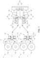
- FIG. 1 is a diagram schematically illustrating a film attaching apparatus according to an embodiment of the present disclosure.
- a film attaching apparatus 1 of the present embodiment may include a tape supply portion 10, a tape connection portion 20, a guide roller 70, a tape cutting portion 30, and a film attaching portion 60.
- the film attaching apparatus 1 may further include a control unit (not shown) controlling operations of respective components.
- the film attaching apparatus 1 of the present embodiment may include a first attaching portion F1 attaching a protective film (140 in FIG. 4 ) to one surface of the battery cell 100 and a second attaching portion F2 attaching the protective film 140 to the other surface of the battery cell 100.
- one surface and the other surface of the battery cell 100 may refer to both surfaces of a portion (hereinafter, a weld zone) in which the electrode tab (110 in FIG. 4 ) and the electrode lead (120 in FIG. 4 ) are welded.
- the first attaching portion F1 and the second attaching portion F2 may be similarly configured and may be disposed to be symmetrical to each other with respect to the battery cell 100.
- first attaching portion F1 and the second attaching portion F2 may include a tape supply portion 10, a tape connection portion 20, a guide roller 70, a tape cutting portion 30, and a film attaching portion 60, and may operate in substantially the same manner.
- the tape supply portion 10 supplies a protective film 140 in the form of a tape to the battery cell 100.
- the film attaching apparatus 1 of the present embodiment may attach the protective film 140 to both surfaces of the weld zone, respectively.
- the tape supply portion 10 can simultaneously supply the protective film 140 to both surfaces of the electrode lead.
- the tape supply portion 10 may include a plurality of supply rolls 11.
- the supply roll 11 may be provided with a protective film 140 wound on a reel in the form of a tape.
- the tape supply unit 10 may include at least two supply rolls 11a and 11b. Therefore, considering the second attaching portion F2, in the present embodiment, at least four supply rolls 11 may be provided, and the four supply rolls 11 may be disposed to be spaced apart from each other by a predetermined distance.
- the tape supply portion 10 may include a first supply roll 11a and a second supply roll 11b.
- One of the first supply roll 11a and the second supply roll 11b may supply a protective film 140 toward the battery cell 10. Another thereof may be preliminarily prepared.
- the protective film 140 of the supply roll 11a if the protective film 140 of the supply roll 11a is exhausted, the supply of the protective film 140 can be prevented from being interrupted by supplying the protective film 140 from the another supply roll (e.g., the second supply roll, 11b) toward the battery cell 100.
- the protective film 140 continuously supplied from the supply roll 11 is referred to as a tape (T), and a member obtained by cutting the tape T to a size that may be attached to the battery cell 100 is referred to as a protective film 140.
- the protective film 140 supplied from the first supply roll 11a is referred to as first tape T1
- the protective film 140 supplied from the second supply roll 11b is referred to as second tape T2.
- the second supply roll 11b when the first supply roll 11a supplies the first tape T1 to the battery cell 100, the second supply roll 11b does not operate.
- the second tape T2 of the second supply roll 11b is connected to the first tape T1 of the first supply roll 11a, and then, the second tape T2 can be supplied to the battery cell 100 from the second supply roll 11b.
- At least one sensor S may be disposed in a position adjacent to the supply roll 11.
- the sensor S may determine a remaining amount of the tape T wound on each supply roll 11.
- the sensor S may determine the remaining amount of tape T based on the number of rotations of the supply roll 11 or a change in a distance from the tape T remaining on the supply roll 11.
- a laser sensor may be used as the sensor S, but the configuration of the present disclosure is not limited thereto.
- the sensor S may be provided on a side of the first supply roll 11a and on a side of the second supply roll 11b, respectively. Accordingly, the control unit (not shown) of the film attaching apparatus 1 may determine whether the first tape T1 supplied from the first supply roll 11a is exhausted through the sensor S, and when it is determined that the first tape T1 is exhausted, the control unit may drive a tape connection portion 20 to attach the second tape T2 of the second supply roll 11b to the first tape T1.
- control unit may determine that the second tape T2 supplied from the second supply roll 11b is exhausted through the sensor S, and when it is determined that the second tape T2 is exhausted, the control unit may drive the tape connection portion 20 to attach the first tape T1 of the first supply roll 11a to the second tape T2.
- the guide roller 70 may be disposed along a travelling path of the tape T supplied from the supply roll 11 to support the tape T. To this end, a plurality of guide rollers 70 may be provided. For example, the plurality of guide rollers 70 may be disposed along a movement path of the tape T formed between the supply roll 11 and the battery cell 100
- tension of the tape T supplied from the supply roll 11 to the battery cell 100 may be maintained constant by the guide rollers 70, or the tape T may support the guide rollers 70 and the travelling direction of the tape T may be changed.
- the tape connection portion 20 may connect the first tape T1 and the second tape T2 to each other. To this end, the tape connection portion 20 may include a support portion 21 and a first cutter 25.
- the support portion 21 may support the tapes T1 and T2 supplied through the supply roll 11.
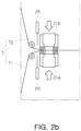
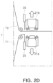
- FIGS. 2A to 2D are diagrams illustrating the operation of the tape connection portion shown in FIG. 1 .
- the support portion 21 may be disposed in? a position spaced apart from the supply roll 11 by a predetermined distance, and may be configured so that a first support portion 21a supporting the first tape T1 and a second support portion 21b supporting the second tape T2 form a pair.
- first support portion 21a and the second support portion 21b may be disposed to be spaced apart from each other by a predetermined distance, and surfaces thereof facing the tape T may be disposed to face each other.
- First tape T1 may be supported on a surface of the first support portion 21a facing the second support portion 21b.
- Second tape T2 may be supported on a surface of the second support portion 21b facing the first support portion 21a. Accordingly, at least a portion of the first tape T1 and the second tape T2 may be disposed to face each other between the first support portion 21a and the second support portion 21b.
- the first support portion 21a and the second support portion 21b may move in a direction toward each other so that the first tape T1 and the second tape T2 may contact each other.
- at least one of the first support portion 21a and the second support portion 21b may be connected to a driving means and configured to enable linear movement in a direction toward each other.
- a linear motor or a hydraulic cylinder may be used as the above-described driving means, but there is no limitation thereto.
- the first tape T1 and the second tape T2 may be bonded to each other.
- the first cutter 25 may be disposed between the support portion 21 and the supply roll 11 and can cut the tape T disposed between the tape supply portion 10 and the tape connection portion 20.
- the film attaching apparatus 1 of the present embodiment when the first tape T1 is exhausted in the process of supplying the first tape T1 to the battery cell 100, a process of attaching second tape T2 to the first tape T1 through the support portion 21, and a process of cutting the first tape T1 using the first cutter 25 may be performed sequentially.
- a process of attaching the first tape T1 to the second tape T2 through the support portion 21, and a process of cutting the second tape T2 using the first cutter 25 may be performed sequentially.
- the first cutter 25 may be respectively disposed between the first supply roll 11a and the first support portion 21a and between the second supply roll 11b and the second support portion 21b, and may be configured to selectively cut the first tape T1 and the second tape.
- the first cutter 25 may be configured to move linearly.
- the first cutter 25 is disposed in a position spaced apart from the tape T by a predetermined distance, and move linearly toward the tape T and cut the tape T.
- the first cutter 25 can be returned to the original position thereof.
- the first cutter 25 may also be connected to a separate driving means and configured to move linearly by a predetermined distance.
- the first cutter 25 moves in a thickness direction of the tape T and cuts the tape T.
- the configuration of the present disclosure is not limited thereto.
- the first cutter 25 may be configured to cut the tape T by moving in the width direction of the tape T.
- the first support portion 21a and the second support portion 21b can move in a direction, away from each other again and return to the original position thereof.
- the second tape T2 may be supplied to the battery cell 100, and the operator can replace the first supply roll 11a with a new supply roll 11 while the second tape T2 is supplied.
- the film attaching apparatus 1 of the present embodiment does not need to stop the film attachment process to replace the supply roll 11, so manufacturing time may be minimized and process efficiency may be improved.
- the tape T supplied from the tape supply portion 10 may pass through the tape connection portion 20 and be disposed in the tape cutting portion 30.
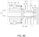
- FIGS. 3A to 3D are diagrams illustrating the operation of the tape cutting portion shown in FIG. 1 .
- a tape T may be cut in the tape cutting portion 30 to a size to be attached to the battery cell 100.
- the tape cutting portion 30 may include a fixing device 40, a fixing moving portion 50, and a second cutter 35.
- the fixing device 40 may suppress the movement of the tape T by pressing the tape T.
- the fixing device 40 of the present embodiment may include a fixing base 31, a rotation pressing portion 32, and a rotation driving portion 33.
- the fixing base 31 may be fixed within the film attaching apparatus 1, and may include a first base 31a disposed to face a first surface of the tape T, and a second base 31b disposed to face a second surface of the tape T.
- the second surface of the tape T refers to an opposite surface of the first surface.
- the first base 31a may have a seating surface on which the tape T is seated. Accordingly, the seating surface may be formed to be substantially flat and disposed to support the first surface of the tape T.
- the second base 31b may be disposed to face the second surface of the tape T, and may be spaced apart from the tape T by a predetermined distance.
- the rotation pressing portion 32 may be rotatably coupled to the second base 31b.
- the rotation pressing portion 32 may be disposed to face the second surface of the tape T, and may be rotatably coupled to the second base 31b.
- the rotation pressing portion 32 may be hingedly coupled to the second base 31b, and may be connected to the rotation driving portion 33 to rotate in a first direction R1 or a second direction R2 by driving the rotation driving portion 33.
- FIG. 3B when the rotation pressing portion 32 rotates in the first direction R1, one end of the rotation pressing portion 32 may contact the tape T to press the tape T toward the first base 31a. In this case, the movement of the tape T may be suppressed.
- FIG. 3A when the rotation pressing portion 32 rotates in the second direction (R2, a direction opposite to the first direction), one end of the rotation pressing portion 32 may be spaced apart from the tape T, as shown in FIG. 3A .
- the rotation driving portion 33 may be fixedly fastened to the second base 31b, and may be configured to allow at least a portion of the rotation driving portion 33 to move linearly in a reciprocating manner, such as a linear motor or a hydraulic cylinder member.
- the other end of the rotation pressing portion 32 may be rotatably coupled to a portion of the rotation driving portion 33, which moves linearly.
- a rotation axis 32a of the rotation pressing portion 32 may be disposed between one end and the other end of the rotation pressing portion 32. Accordingly, one end of the rotation pressing portion 32 may be rotated in the first direction R1 or the second direction R2 in response to the linear movement of the rotation driving portion 33.
- the configuration of the present disclosure is not limited thereto, and it is also possible to configure the rotation driving portion 33 as a rotation device such as a motor.
- the rotation axis 32a of the rotation driving portion 33 can be used as a rotation axis of the rotation pressing portion 32.
- the fixing moving portion 50 may pull the tape T located in the tape cutting unit 30 out of the tape cutting portion 30 by a predetermined length. To this end, at least a portion of the fixing moving portion 50 may be disposed to enable reciprocating movement in a pulling direction of the tape T.
- the fixing moving portion 50 may be coupled to a moving rail and configured to enable linear movement according to the operation of the driving means.
- the fixing moving portion 50 may be provided with a gripping unit 52 gripping an end of the tape T.
- the gripping unit 52 may be formed in the shape of pincers to simultaneously press upper and lower surfaces of the end of the tape T1 and grip the tape T. In this process, the gripping unit 52 may adsorb the tape T and grip the tape T, but the configuration of the present disclosure is not limited thereto.
- the gripping unit 52 when the gripping unit 52 grips the end of the tape T, the gripping unit 52 may move in a direction, away from the fixing device 40, as shown in FIG. 3B , the tape T may be pulled out of the fixing device 40.
- the second cutter 35 may cut the tape T pulled out of the fixing device 40. As shown in FIG. 3D , the second cutter 35 may be disposed between the fixing device 40 and the fixing moving portion 50 and may cut the tape T located between the fixing device 40 and the fixing moving portion 50.
- the film attaching apparatus 1 of the present embodiment may be configured so that the second cutter 35 cuts the tape T.
- the second cutter 35 may be disposed in a position adjacent to the fixing device 40, and may be configured to be connected to a separate driving means to move linearly by a predetermined distance.
- the second cutter 35 moves in a thickness direction of the tape T to cut the tape T.
- the configuration of the present disclosure is not limited thereto.
- the second cutter 35 may be configured to move in a width direction of the tape T and cut the tape T.
- the fixing moving portion 50 moves toward the fixing device 40 to grip the end of the tape T, and then returns to the original position thereof, as shown in FIG. 3B . Accordingly, the tape T is pulled out from the fixing device 40 and disposed in a region between the fixing device 40 and the fixing moving portion 50. In this process, the rotation pressing portion 32 may maintain an end thereof spaced apart from the tape T, as shown in FIG. 3A .
- the rotation driving portion 33 rotates the rotation pressing portion 32 in the first direction. Accordingly, as shown in FIG. 3B , the end of the rotation pressing portion 32 presses the tape T toward a first base 31a and fixes the tape to the first base 31a.
- the tape T, cut by the second cutter 35, that is, the protective film 140, may be attached to the battery cell 100 through the film attaching portion 60.
- the film attaching portion 60 may adsorb the protective film 140 located between the fixing device 40 and the fixed moving portion 50, transfer the same toward the battery cell 100, and then attach the same to the battery cell 100.
- FIG. 4 is a perspective view specifically illustrating film attaching portion shown in FIG. 1 .
- the film attaching portion 60 of the present embodiment may include an adsorption portion 61 and a transfer portion 65.
- the adsorption portion 61 may be disposed between the fixing device 40 and the fixing moving portion 50 (A1, hereinafter, referred to as an adsorption area to adsorb the protective film 140, and then move to an area (A2, hereinafter, referred to as an attachment area) in which the battery cell 100 is disposed and attach the adsorbed protective film 140 to the battery cell 100.
- the adsorption portion 61 may be provided with a plurality of suction ports on a surface thereof adsorbing the protective film 140.
- the adsorption area A1 and the attachment area A2 may be disposed to be spaced apart from each other by a predetermined distance, and the adsorption portion 61 may alternately move between the adsorption area A1 and the attachment area A2 by the transfer portion 65.
- the adsorption portion 61 may be configured to rotate through the transfer portion 65.
- the adsorption portion 61 may be rotated by a predetermined angle based on a rotation axis P of the transfer portion 65 and disposed in the adsorption area A1 or the attachment area A2.
- the transfer portion 65 may include a driving means capable of rotating the adsorption portion 61, such as a motor.
- the adsorption portion 61 may be disposed above or below the protective film 140, move linearly toward the protective film 140 to adsorb the protective film 140, and then return to the original position thereof.
- the adsorption portion 61 may be located above or below the battery cell 100, move linearly toward the battery cell 100, attach the protective film 140 to the battery cell 100, and then return to the original position thereof.
- the transfer portion 65 may include a driving means which linearly moves the adsorption portion 61, such as a hydraulic or pneumatic cylinder.
- the film attaching portion 60 of the present embodiment may be configured such that at least two adsorption portions 61a and 61b are simultaneously located in the adsorption area A1 and the attachment area A2, respectively.
- the other adsorption portion 61b (hereinafter, referred to as a second adsorption portion) may be configured to move from the attachment area A2 to the adsorption area A1.
- the second adsorption portion 61b may attach the protective film 140 to the battery cell 100. Therefore, adsorption and attachment of the protective film 140 may be performed simultaneously, thereby reducing the time required for the process.
- a case in which one adsorption area A1 and one attachment area A2 are provided is taken as an example, but the present disclosure is not limited thereto, and a plurality of adsorption areas A1 and a plurality of attachment areas A2 may also be provided, as required.
- the first tape T1 is supplied from the first supply roll 11a toward the tape connection portion 20.
- the second supply roll (11b) does not operate.
- the first tape T1 that has passed the tape connection portion 20 supports guide rollers 70 and is supplied toward the tape cutting portion 30.
- the fixing moving portion 50 first moves toward the fixing device 40, grips one end of the tape T, and returns to the original position thereof while the tape T is gripped. Accordingly, the tape T is disposed in the adsorption area (A1 in FIG. 4 ), which is a space between the fixing device 40 and the fixing moving portion 50.
- a tape adsorption process in which the first adsorption portion 61a of the film attaching portion 60 adsorbs the tape T located in the adsorption area A1 may be performed.
- the rotation pressing portion 32 adsorbs the tape T, and the tape T is fixed to be engaged between the rotation pressing portion 32 and the first base 31a.
- the tape T is formed of a protective film 140 of a size that can be attached to the battery cell 100.
- a transfer process of transferring the first adsorption portion 61a to the attachment area A2 is performed.
- the first adsorption portion 61a may be transferred to the attachment area A2 by driving the transfer portion 65 by rotation.
- the above-described tape pulling process ( FIGS. 3a , 3b ) in which the fixed moving portion 50 grips the end of the tape T and pulls the tape T out of the fixing device 40 may be performed. Accordingly, when the first adsorption portion 61a is located in the attachment area A2, the tape T may be disposed again in the adsorption area A1.
- the first adsorption portion 61a When the first adsorption portion 61a is located in the attachment area A2, a process of attaching the protective film 140 adsorbed to the first adsorption portion 61a to the battery cell 100 may be performed.
- the transfer portion 65 may move the first adsorption portion 61a toward the battery cell 100, and thus the protective film 140 may contact the battery cell 100 and may be attached to a weld zone of the battery cell 100.
- the tape adsorption process and the tape cutting process shown in FIGS. 3C and 3D may be performed in the adsorption area A1.
- the tape adsorption process can be performed through the second adsorption portion 61b.
- the first adsorption portion 61a returns to the original position thereof, and a process in which the second adsorption portion 61b to which the protective film 140 is adsorbed, is transferred and the protective film 140 is attached, is repeatedly performed.
- At least one of the first support portion 21a and the second support portion 21b may move in a direction, toward each other, and thus the first tape T1 and the second tape T2 may contact each other, and be bonded to each other.
- the first cutter 25 cuts the first tape T1 located between the first supply roll 11a and the support portion 21. Subsequently, as shown in FIG. 2D , when the first support portion 21a and the second support portion 21b return to the original positions thereof, the second tape T2 connected to the first tape T1 may be supplied toward the battery cell 100. In this case, a portion in which the first tape T1 and the second tape T2 are bonded may be discarded from the tape cutting portion 30.
- the first supply roll 11a does not operate. Therefore, the operator can replace the first supply roll 11a with a new supply roll 11 while the tape T is supplied from the second supply roll 11b.
- the film attaching apparatus configured in this manner does not need to stop the film attachment process to replace the supply roll when the tape supplied from the supply roll is exhausted, manufacturing time may be reduced and process efficiency may be improved.
- the adsorption and attachment of the protective film can be performed simultaneously, thereby reducing the time required for the process.
Landscapes
- Chemical & Material Sciences (AREA)
- Chemical Kinetics & Catalysis (AREA)
- Electrochemistry (AREA)
- General Chemical & Material Sciences (AREA)
- Engineering & Computer Science (AREA)
- Manufacturing & Machinery (AREA)
- Battery Mounting, Suspending (AREA)
Abstract
Description
- The present disclosure relates to an apparatus for attaching a protective film to a weld zone of an electrode lead and an electrode tab during a battery cell manufacturing process.
- Unlike primary batteries, battery cells may be charged and discharged, so the battery cells may be applied to devices within various fields such as digital cameras, mobile phones, laptops, hybrid cars, and electric vehicles. Recently, among battery cells, much research is being conducted on lithium battery cells with high energy density and discharge voltage.
- Generally, lithium battery cells are manufactured as pouch-type battery cells having flexibility, or as prismatic battery cells or cylindrical can-type battery cells having rigidity.
- Double pouch-type battery cells have a protective film attached to a portion in which an electrode lead and an electrode tab are welded to each other. The protective film is provided to prevent an exterior material from being damaged due to burrs, generated in the welded portion.
- Accordingly, the present disclosure proposes an apparatus and method that can more easily attach a protective film to the welded portion during the battery cell manufacturing process.
- An aspect of the present disclosure is to provide a film attaching apparatus that can easily attach a protective film to a battery cell.
- According to an aspect of the present disclosure, a film attaching apparatus may include: a tape supply portion selectively supplying first tape provided on a first supply roll and second tape provided on a second supply roll; a tape cutting portion cutting the first tape or the second tape to a predetermined size; a film attaching portion attaching a protective film formed by cutting the first tape or the second tape to a battery cell; and a tape connection portion connecting the first tape and the second tape, when one of the first tape and the second tape is exhausted.
- In an embodiment of the present disclosure, the tape connection portion may include a first support portion and a second support portion disposed to be spaced apart from each other by a predetermined distance, the first tape and the second tape may be disposed to pass between the first support portion and the second support portion, and when the first tape is exhausted, the first support portion and the second support portion may move in a direction toward each other, to bond the first tape and the second tape to each other.
- In an embodiment of the present disclosure, when the first tape and the second tape are bonded to each other, a cutter cutting the exhausted tape of the first tape and the second tape may be further included.
- In an embodiment of the present disclosure, a plurality of guide rollers supporting the first tape or the second tape and maintaining tension of the first tape or the second tape may be further included.
- In an embodiment of the present disclosure, a sensor sensing a remaining amount of the first tape on the first supply roll may be further included.
- In an embodiment of the present disclosure, the tape connection portion may be disposed between the tape supply portion and the tape cutting portion.
- In an embodiment of the present disclosure, the tape cutting portion may include a fixing device supporting the tape supplied from the tape supply portion, a fixing moving portion disposed to enable linear movement toward the fixing device and pulling out the tape disposed on the fixing device to the outside of the fixing device by a predetermined distance, and a cutter disposed between the fixing device and the fixing moving portion to cut the tape.
- In an embodiment of the present disclosure, when the tape is pulled out by a predetermined distance by the fixing moving portion, the fixing device may press the tape to suppress the movement of the tape.
- In an embodiment of the present disclosure, the fixing moving portion may include a gripping unit formed in a pincer shape and gripping the tape.
- In an embodiment of the present disclosure, the film attaching portion may include an adsorption portion adsorbing the protective film to attach the protective film to the battery cell, and a transfer portion disposing the adsorption portion between the fixing device and the fixing moving portion and disposing the adsorption portion to face the battery cell.
- In an embodiment of the present disclosure, the adsorption portion may include a first adsorption portion and a second adsorption portion, disposed to be spaced apart from each other by a predetermined distance, and when the first adsorption portion is disposed between the fixing device and the fixing moving portion, the transfer portion may dispose the second adsorption portion to face the battery cell.
- In an embodiment of the present disclosure, when the first adsorption portion adsorbs the protective film, the second adsorption portion may attach the pre-adsorbed protective film to the battery cell.
- As set forth above, according to an embodiment of the present disclosure, when a tape supplied from a supply roll is exhausted, a film attaching apparatus does not need to stop a film attachment process to replace the supply roll, so manufacturing time may be reduced and process efficiency may be improved.
-
-
FIG. 1 is a diagram schematically illustrating a film attaching apparatus according to an embodiment of the present disclosure. -
FIGS. 2A to 2D are diagrams illustrating an operation of the tape connection portion shown inFIG. 1 . -
FIGS. 3A to 3D are diagrams illustrating an operation of the tape cutting portion shown inFIG. 1 . -
FIG. 4 is a perspective view specifically illustrating the film attaching portion shown inFIG. 1 . - Hereinafter, preferred embodiments of the present disclosure will be described in detail with reference to the attached drawings. In this case, detailed descriptions of well-known functions and configurations that may obscure the gist of the present disclosure may be omitted in the attached drawings. In addition, in the accompanying drawings, some components are exaggerated, omitted, or schematically shown, and the size of each component does not entirely reflect the actual size.
- In addition, in the embodiment of the present disclosure, expressions such as upper, lower, lower, and side are explained based on the drawings, and may be expressed differently when the direction of the object in question changes.
- In addition, the battery cell described below may be a lithium secondary battery, and the description will be based on a pouch-type battery cell having an exterior material having flexibility. However, the configuration of the present disclosure is not limited thereto.
- In addition, in the following description, the
battery cell 100 is in a manufacturing state rather than a completed state, which may mean a state in which anelectrode 120 is welded to anelectrode tab 110 of theelectrode assembly 130 as shown inFIG. 4 . - The present disclosure relates to a film attaching apparatus automatically attaching a
protective film 140 to a welded portion (hereinafter, referred to as a weld zone) in which the electrode lead (120 inFIG. 4 ) and theelectrode tab 110 are welded to each other. -
FIG. 1 is a diagram schematically illustrating a film attaching apparatus according to an embodiment of the present disclosure. - Referring to
FIG. 1 , a film attaching apparatus 1 of the present embodiment may include atape supply portion 10, atape connection portion 20, aguide roller 70, atape cutting portion 30, and afilm attaching portion 60. In addition, the film attaching apparatus 1 may further include a control unit (not shown) controlling operations of respective components. - The film attaching apparatus 1 of the present embodiment may include a first attaching portion F1 attaching a protective film (140 in
FIG. 4 ) to one surface of thebattery cell 100 and a second attaching portion F2 attaching theprotective film 140 to the other surface of thebattery cell 100. Here, one surface and the other surface of thebattery cell 100 may refer to both surfaces of a portion (hereinafter, a weld zone) in which the electrode tab (110 inFIG. 4 ) and the electrode lead (120 inFIG. 4 ) are welded. - The first attaching portion F1 and the second attaching portion F2 may be similarly configured and may be disposed to be symmetrical to each other with respect to the
battery cell 100. - In addition, the first attaching portion F1 and the second attaching portion F2 may include a
tape supply portion 10, atape connection portion 20, aguide roller 70, atape cutting portion 30, and afilm attaching portion 60, and may operate in substantially the same manner. - Therefore, hereinafter, for convenience of explanation, the description will be provided based on the first attaching portion F1, and only portions that are different from the first attaching portion F1 will be described regarding the second attaching portion F2.
- The
tape supply portion 10 supplies aprotective film 140 in the form of a tape to thebattery cell 100. - The film attaching apparatus 1 of the present embodiment may attach the
protective film 140 to both surfaces of the weld zone, respectively. To this end, thetape supply portion 10 can simultaneously supply theprotective film 140 to both surfaces of the electrode lead. - The
tape supply portion 10 may include a plurality ofsupply rolls 11. Thesupply roll 11 may be provided with aprotective film 140 wound on a reel in the form of a tape. - The
tape supply unit 10 may include at least twosupply rolls supply rolls 11 may be provided, and the foursupply rolls 11 may be disposed to be spaced apart from each other by a predetermined distance. - In the present embodiment, the
tape supply portion 10 may include afirst supply roll 11a and asecond supply roll 11b. One of thefirst supply roll 11a and thesecond supply roll 11b may supply aprotective film 140 toward thebattery cell 10. Another thereof may be preliminarily prepared. For example, in the process of supplying theprotective film 140 from one supply roll (e.g., the first supply roll, 11a) to thebattery cell 100, if theprotective film 140 of thesupply roll 11a is exhausted, the supply of theprotective film 140 can be prevented from being interrupted by supplying theprotective film 140 from the another supply roll (e.g., the second supply roll, 11b) toward thebattery cell 100. - Hereinafter, the
protective film 140 continuously supplied from thesupply roll 11 is referred to as a tape (T), and a member obtained by cutting the tape T to a size that may be attached to thebattery cell 100 is referred to as aprotective film 140. In addition, theprotective film 140 supplied from thefirst supply roll 11a is referred to as first tape T1, and theprotective film 140 supplied from thesecond supply roll 11b is referred to as second tape T2. - In the film attaching apparatus 1 of the present embodiment, when the
first supply roll 11a supplies the first tape T1 to thebattery cell 100, thesecond supply roll 11b does not operate. When the first tape T1 of thefirst supply roll 11a is exhausted, the second tape T2 of thesecond supply roll 11b is connected to the first tape T1 of thefirst supply roll 11a, and then, the second tape T2 can be supplied to thebattery cell 100 from thesecond supply roll 11b. - At least one sensor S may be disposed in a position adjacent to the
supply roll 11. The sensor S may determine a remaining amount of the tape T wound on eachsupply roll 11. For example, the sensor S may determine the remaining amount of tape T based on the number of rotations of thesupply roll 11 or a change in a distance from the tape T remaining on thesupply roll 11. A laser sensor may be used as the sensor S, but the configuration of the present disclosure is not limited thereto. - The sensor S may be provided on a side of the
first supply roll 11a and on a side of thesecond supply roll 11b, respectively. Accordingly, the control unit (not shown) of the film attaching apparatus 1 may determine whether the first tape T1 supplied from thefirst supply roll 11a is exhausted through the sensor S, and when it is determined that the first tape T1 is exhausted, the control unit may drive atape connection portion 20 to attach the second tape T2 of thesecond supply roll 11b to the first tape T1. - Likewise, the control unit (not shown) may determine that the second tape T2 supplied from the
second supply roll 11b is exhausted through the sensor S, and when it is determined that the second tape T2 is exhausted, the control unit may drive thetape connection portion 20 to attach the first tape T1 of thefirst supply roll 11a to the second tape T2. - The
guide roller 70 may be disposed along a travelling path of the tape T supplied from thesupply roll 11 to support the tape T. To this end, a plurality ofguide rollers 70 may be provided. For example, the plurality ofguide rollers 70 may be disposed along a movement path of the tape T formed between thesupply roll 11 and thebattery cell 100 - Accordingly, tension of the tape T supplied from the
supply roll 11 to thebattery cell 100 may be maintained constant by theguide rollers 70, or the tape T may support theguide rollers 70 and the travelling direction of the tape T may be changed. - The
tape connection portion 20 may connect the first tape T1 and the second tape T2 to each other. To this end, thetape connection portion 20 may include asupport portion 21 and afirst cutter 25. - The
support portion 21 may support the tapes T1 and T2 supplied through thesupply roll 11. -
FIGS. 2A to 2D are diagrams illustrating the operation of the tape connection portion shown inFIG. 1 . - Referring to
FIGS. 2A to 2D together, thesupport portion 21 may be disposed in? a position spaced apart from thesupply roll 11 by a predetermined distance, and may be configured so that afirst support portion 21a supporting the first tape T1 and asecond support portion 21b supporting the second tape T2 form a pair. - As shown in
FIG. 2A , thefirst support portion 21a and thesecond support portion 21b may be disposed to be spaced apart from each other by a predetermined distance, and surfaces thereof facing the tape T may be disposed to face each other. - First tape T1 may be supported on a surface of the
first support portion 21a facing thesecond support portion 21b. Second tape T2 may be supported on a surface of thesecond support portion 21b facing thefirst support portion 21a. Accordingly, at least a portion of the first tape T1 and the second tape T2 may be disposed to face each other between thefirst support portion 21a and thesecond support portion 21b. - As shown in
FIG. 2B , thefirst support portion 21a and thesecond support portion 21b may move in a direction toward each other so that the first tape T1 and the second tape T2 may contact each other. For example, at least one of thefirst support portion 21a and thesecond support portion 21b may be connected to a driving means and configured to enable linear movement in a direction toward each other. A linear motor or a hydraulic cylinder may be used as the above-described driving means, but there is no limitation thereto. - As the first tape T1 and the second tape T2 contact each other, the first tape T1 and the second tape T2 may be bonded to each other.
- When the first tape T1 and the second tape T2 are bonded to each other, a process of separating the exhausted tape from the
supply roll 11 using thefirst cutter 25 is performed, as shown inFIG. 2C . - The
first cutter 25 may be disposed between thesupport portion 21 and thesupply roll 11 and can cut the tape T disposed between thetape supply portion 10 and thetape connection portion 20. - For example, in the film attaching apparatus 1 of the present embodiment, when the first tape T1 is exhausted in the process of supplying the first tape T1 to the
battery cell 100, a process of attaching second tape T2 to the first tape T1 through thesupport portion 21, and a process of cutting the first tape T1 using thefirst cutter 25 may be performed sequentially. Likewise, when the second tape T2 is exhausted in the process of supplying the second tape T2 to thebattery cell 100, a process of attaching the first tape T1 to the second tape T2 through thesupport portion 21, and a process of cutting the second tape T2 using thefirst cutter 25 may be performed sequentially. - Therefore, the
first cutter 25 may be respectively disposed between thefirst supply roll 11a and thefirst support portion 21a and between thesecond supply roll 11b and thesecond support portion 21b, and may be configured to selectively cut the first tape T1 and the second tape. - For cutting the tape T, the
first cutter 25 may be configured to move linearly. For example, thefirst cutter 25 is disposed in a position spaced apart from the tape T by a predetermined distance, and move linearly toward the tape T and cut the tape T. When cutting is completed, thefirst cutter 25 can be returned to the original position thereof. To this end, thefirst cutter 25 may also be connected to a separate driving means and configured to move linearly by a predetermined distance. - In the present embodiment, the
first cutter 25 moves in a thickness direction of the tape T and cuts the tape T. However, the configuration of the present disclosure is not limited thereto. For example, thefirst cutter 25 may be configured to cut the tape T by moving in the width direction of the tape T. - When the tape T is cut by the
first cutter 25, as shown inFIG. 2D , thefirst support portion 21a and thesecond support portion 21b can move in a direction, away from each other again and return to the original position thereof. - Thereafter, the second tape T2 may be supplied to the
battery cell 100, and the operator can replace thefirst supply roll 11a with anew supply roll 11 while the second tape T2 is supplied. - Through this configuration, when the tape T supplied from the
supply roll 11 is exhausted, the film attaching apparatus 1 of the present embodiment does not need to stop the film attachment process to replace thesupply roll 11, so manufacturing time may be minimized and process efficiency may be improved. - The tape T supplied from the
tape supply portion 10 may pass through thetape connection portion 20 and be disposed in thetape cutting portion 30. -
FIGS. 3A to 3D are diagrams illustrating the operation of the tape cutting portion shown inFIG. 1 . - Referring to
FIGS. 3A to 3D together, a tape T may be cut in thetape cutting portion 30 to a size to be attached to thebattery cell 100. To this end, thetape cutting portion 30 may include a fixingdevice 40, afixing moving portion 50, and asecond cutter 35. - The fixing
device 40 may suppress the movement of the tape T by pressing the tape T. To this end, the fixingdevice 40 of the present embodiment may include a fixingbase 31, arotation pressing portion 32, and arotation driving portion 33. - The fixing
base 31 may be fixed within the film attaching apparatus 1, and may include afirst base 31a disposed to face a first surface of the tape T, and asecond base 31b disposed to face a second surface of the tape T. Here, the second surface of the tape T refers to an opposite surface of the first surface. - The
first base 31a may have a seating surface on which the tape T is seated. Accordingly, the seating surface may be formed to be substantially flat and disposed to support the first surface of the tape T. - The
second base 31b may be disposed to face the second surface of the tape T, and may be spaced apart from the tape T by a predetermined distance. Therotation pressing portion 32 may be rotatably coupled to thesecond base 31b. - The
rotation pressing portion 32 may be disposed to face the second surface of the tape T, and may be rotatably coupled to thesecond base 31b. Therotation pressing portion 32 may be hingedly coupled to thesecond base 31b, and may be connected to therotation driving portion 33 to rotate in a first direction R1 or a second direction R2 by driving therotation driving portion 33. - As shown in
FIG. 3B , when therotation pressing portion 32 rotates in the first direction R1, one end of therotation pressing portion 32 may contact the tape T to press the tape T toward thefirst base 31a. In this case, the movement of the tape T may be suppressed. As shown inFIG. 3A , when therotation pressing portion 32 rotates in the second direction (R2, a direction opposite to the first direction), one end of therotation pressing portion 32 may be spaced apart from the tape T, as shown inFIG. 3A . - The
rotation driving portion 33 may be fixedly fastened to thesecond base 31b, and may be configured to allow at least a portion of therotation driving portion 33 to move linearly in a reciprocating manner, such as a linear motor or a hydraulic cylinder member. In addition, the other end of therotation pressing portion 32 may be rotatably coupled to a portion of therotation driving portion 33, which moves linearly. - A
rotation axis 32a of therotation pressing portion 32 may be disposed between one end and the other end of therotation pressing portion 32. Accordingly, one end of therotation pressing portion 32 may be rotated in the first direction R1 or the second direction R2 in response to the linear movement of therotation driving portion 33. - However, the configuration of the present disclosure is not limited thereto, and it is also possible to configure the
rotation driving portion 33 as a rotation device such as a motor. In this case, therotation axis 32a of therotation driving portion 33 can be used as a rotation axis of therotation pressing portion 32. - The
fixing moving portion 50 may pull the tape T located in thetape cutting unit 30 out of thetape cutting portion 30 by a predetermined length. To this end, at least a portion of thefixing moving portion 50 may be disposed to enable reciprocating movement in a pulling direction of the tape T. For example, thefixing moving portion 50 may be coupled to a moving rail and configured to enable linear movement according to the operation of the driving means. - The
fixing moving portion 50 may be provided with a grippingunit 52 gripping an end of the tape T. The grippingunit 52 may be formed in the shape of pincers to simultaneously press upper and lower surfaces of the end of the tape T1 and grip the tape T. In this process, the grippingunit 52 may adsorb the tape T and grip the tape T, but the configuration of the present disclosure is not limited thereto. - As shown in
FIG. 3A , when the grippingunit 52 grips the end of the tape T, the grippingunit 52 may move in a direction, away from the fixingdevice 40, as shown inFIG. 3B , the tape T may be pulled out of the fixingdevice 40. - The
second cutter 35 may cut the tape T pulled out of the fixingdevice 40. As shown inFIG. 3D , thesecond cutter 35 may be disposed between the fixingdevice 40 and thefixing moving portion 50 and may cut the tape T located between the fixingdevice 40 and thefixing moving portion 50. - When the tape T is pulled out of the fixing
device 40 by a predetermined length (a length of the protective film 140), the film attaching apparatus 1 of the present embodiment may be configured so that thesecond cutter 35 cuts the tape T. To this end, thesecond cutter 35 may be disposed in a position adjacent to the fixingdevice 40, and may be configured to be connected to a separate driving means to move linearly by a predetermined distance. - In the present embodiment, the
second cutter 35 moves in a thickness direction of the tape T to cut the tape T. However, the configuration of the present disclosure is not limited thereto. For example, thesecond cutter 35 may be configured to move in a width direction of the tape T and cut the tape T. - Subsequently, a process of cutting the tape T through the
tape cutting portion 30 will be described in more detail. - First, as shown in
FIG. 1 , when the tape T is disposed on the fixingdevice 40, as shown inFIG. 3A , thefixing moving portion 50 moves toward the fixingdevice 40 to grip the end of the tape T, and then returns to the original position thereof, as shown inFIG. 3B . Accordingly, the tape T is pulled out from the fixingdevice 40 and disposed in a region between the fixingdevice 40 and thefixing moving portion 50. In this process, therotation pressing portion 32 may maintain an end thereof spaced apart from the tape T, as shown inFIG. 3A . - Subsequently, the
rotation driving portion 33 rotates therotation pressing portion 32 in the first direction. Accordingly, as shown inFIG. 3B , the end of therotation pressing portion 32 presses the tape T toward afirst base 31a and fixes the tape to thefirst base 31a. - Subsequently, as shown in
FIG. 3C , when a film attaching portion to be described later adsorbs the tape T, a process in which thesecond cutter 35 cuts the tape T may be performed, as shown inFIG. 3D . - In this process, since the
rotation pressing portion 32 continuously presses the tape T, it is possible to prevent the tape T from moving or being additionally pulled out in the process of cutting the tape T. In addition, after the tape T is cut, it is also possible to prevent the end of the tape T disposed on thefirst base 31a from being rolled into thetape connection portion 20. - The tape T, cut by the
second cutter 35, that is, theprotective film 140, may be attached to thebattery cell 100 through thefilm attaching portion 60. - The
film attaching portion 60 may adsorb theprotective film 140 located between the fixingdevice 40 and the fixed movingportion 50, transfer the same toward thebattery cell 100, and then attach the same to thebattery cell 100. -
FIG. 4 is a perspective view specifically illustrating film attaching portion shown inFIG. 1 . - Referring to
FIG. 4 together, thefilm attaching portion 60 of the present embodiment may include anadsorption portion 61 and atransfer portion 65. - The
adsorption portion 61 may be disposed between the fixingdevice 40 and the fixing moving portion 50 (A1, hereinafter, referred to as an adsorption area to adsorb theprotective film 140, and then move to an area (A2, hereinafter, referred to as an attachment area) in which thebattery cell 100 is disposed and attach the adsorbedprotective film 140 to thebattery cell 100. To this end, theadsorption portion 61 may be provided with a plurality of suction ports on a surface thereof adsorbing theprotective film 140. - The adsorption area A1 and the attachment area A2 may be disposed to be spaced apart from each other by a predetermined distance, and the
adsorption portion 61 may alternately move between the adsorption area A1 and the attachment area A2 by thetransfer portion 65. - In the present embodiment, the
adsorption portion 61 may be configured to rotate through thetransfer portion 65. For example, theadsorption portion 61 may be rotated by a predetermined angle based on a rotation axis P of thetransfer portion 65 and disposed in the adsorption area A1 or the attachment area A2. To this end, thetransfer portion 65 may include a driving means capable of rotating theadsorption portion 61, such as a motor. - In addition, in the adsorption area A1, the
adsorption portion 61 may be disposed above or below theprotective film 140, move linearly toward theprotective film 140 to adsorb theprotective film 140, and then return to the original position thereof. Similarly, in the attachment area, theadsorption portion 61 may be located above or below thebattery cell 100, move linearly toward thebattery cell 100, attach theprotective film 140 to thebattery cell 100, and then return to the original position thereof. To this end, thetransfer portion 65 may include a driving means which linearly moves theadsorption portion 61, such as a hydraulic or pneumatic cylinder. - The
film attaching portion 60 of the present embodiment may be configured such that at least twoadsorption portions adsorption portion 61a (hereinafter, referred to as a first adsorption portion) moves from the adsorption area A1 to the attachment area A2, by driving thetransfer portion 65 by rotation, theother adsorption portion 61b (hereinafter, referred to as a second adsorption portion) may be configured to move from the attachment area A2 to the adsorption area A1. - In this case, when the
first adsorption portion 61a adsorbs theprotective film 140, thesecond adsorption portion 61b may attach theprotective film 140 to thebattery cell 100. Therefore, adsorption and attachment of theprotective film 140 may be performed simultaneously, thereby reducing the time required for the process. - Meanwhile, in the present embodiment, a case in which one adsorption area A1 and one attachment area A2 are provided is taken as an example, but the present disclosure is not limited thereto, and a plurality of adsorption areas A1 and a plurality of attachment areas A2 may also be provided, as required.
- Hereinafter, a method of attaching the
protective film 140 to thebattery cell 100 using the apparatus for attaching a film 1 according to an embodiment of the present disclosure will be described in its entirety. - Referring to
FIG. 1 , first, the first tape T1 is supplied from thefirst supply roll 11a toward thetape connection portion 20. In this case, the second supply roll (11b) does not operate. - The first tape T1 that has passed the
tape connection portion 20 supports guiderollers 70 and is supplied toward thetape cutting portion 30. - When the first tape T1 is disposed on the fixing
device 40 of thetape cutting portion 30, a process for attaching a film is performed. Referring toFIGS. 3A and3B , thefixing moving portion 50 first moves toward the fixingdevice 40, grips one end of the tape T, and returns to the original position thereof while the tape T is gripped. Accordingly, the tape T is disposed in the adsorption area (A1 inFIG. 4 ), which is a space between the fixingdevice 40 and thefixing moving portion 50. - Subsequently, as shown in
FIG. 3C , a tape adsorption process in which thefirst adsorption portion 61a of thefilm attaching portion 60 adsorbs the tape T located in the adsorption area A1 may be performed. In this process, therotation pressing portion 32 adsorbs the tape T, and the tape T is fixed to be engaged between therotation pressing portion 32 and thefirst base 31a. - Subsequently, as shown in
FIG. 3D , a tape cutting process in which thesecond cutter 35 moves toward the tape T and cuts the tape T1 is performed. Accordingly, the tape T is formed of aprotective film 140 of a size that can be attached to thebattery cell 100. - Subsequently, a transfer process of transferring the
first adsorption portion 61a to the attachment area A2 is performed. As shown inFIG. 4 , thefirst adsorption portion 61a may be transferred to the attachment area A2 by driving thetransfer portion 65 by rotation. - Meanwhile, simultaneously, the above-described tape pulling process (
FIGS. 3a ,3b ) in which the fixed movingportion 50 grips the end of the tape T and pulls the tape T out of the fixingdevice 40 may be performed. Accordingly, when thefirst adsorption portion 61a is located in the attachment area A2, the tape T may be disposed again in the adsorption area A1. - When the
first adsorption portion 61a is located in the attachment area A2, a process of attaching theprotective film 140 adsorbed to thefirst adsorption portion 61a to thebattery cell 100 may be performed. Thetransfer portion 65 may move thefirst adsorption portion 61a toward thebattery cell 100, and thus theprotective film 140 may contact thebattery cell 100 and may be attached to a weld zone of thebattery cell 100. - At the same time, the tape adsorption process and the tape cutting process shown in
FIGS. 3C and3D may be performed in the adsorption area A1. Here, the tape adsorption process can be performed through thesecond adsorption portion 61b. - Subsequently, when the
protective film 140 is attached to thebattery cell 100, thefirst adsorption portion 61a returns to the original position thereof, and a process in which thesecond adsorption portion 61b to which theprotective film 140 is adsorbed, is transferred and theprotective film 140 is attached, is repeatedly performed. - Meanwhile, in the process of repeatedly performing the attachment process, when it is determined that the first tape T1 wound around the
first supply roll 11a is almost exhausted through a sensor S, a process of connecting the second tape T2 to the first tape T1 may be performed. - Specifically, when it is confirmed that the first tape T1 is exhausted, as shown in
FIG. 2B , at least one of thefirst support portion 21a and thesecond support portion 21b may move in a direction, toward each other, and thus the first tape T1 and the second tape T2 may contact each other, and be bonded to each other. - When the first tape T1 and the second tape T2 are bonded to each other, as shown in
FIG. 2C , thefirst cutter 25 cuts the first tape T1 located between thefirst supply roll 11a and thesupport portion 21. Subsequently, as shown inFIG. 2D , when thefirst support portion 21a and thesecond support portion 21b return to the original positions thereof, the second tape T2 connected to the first tape T1 may be supplied toward thebattery cell 100. In this case, a portion in which the first tape T1 and the second tape T2 are bonded may be discarded from thetape cutting portion 30. - Meanwhile, while the second tape T2 is supplied from the
second supply roll 11b, thefirst supply roll 11a does not operate. Therefore, the operator can replace thefirst supply roll 11a with anew supply roll 11 while the tape T is supplied from thesecond supply roll 11b. - Since the film attaching apparatus according to an embodiment of the present disclosure configured in this manner does not need to stop the film attachment process to replace the supply roll when the tape supplied from the supply roll is exhausted, manufacturing time may be reduced and process efficiency may be improved.
- In addition, the adsorption and attachment of the protective film can be performed simultaneously, thereby reducing the time required for the process.
- While example embodiments have been illustrated and described above, it will be apparent to those skilled in the art that modifications and variations could be made without departing from the scope of the present disclosure as defined by the appended claims.
Claims (12)
- A film attaching apparatus, comprising:a tape supply portion selectively supplying first tape provided on a first supply roll and second tape provided on a second supply roll;a tape cutting portion cutting the first tape or the second tape to a predetermined size;a film attaching portion attaching a protective film formed by cutting the first tape or the second tape to a battery cell; anda tape connection portion connecting the first tape and the second tape, when one of the first tape and the second tape is exhausted.
- The film attaching apparatus of claim 1, wherein the tape connection portion comprises a first support portion and a second support portion disposed to be spaced apart from each other by a predetermined distance,the first tape and the second tape are disposed to pass between the first support portion and the second support portion, andwhen any one of the first tape and the second tape is exhausted, the first support portion and the second support portion move in a direction, toward each other, to bond the first tape and the second tape to each other.
- The film attaching apparatus of claim 2, further comprising:
a cutter cutting the exhausted tape of the first tape and the second tape, when the first tape and the second tape are bonded to each other. - The film attaching apparatus of claim 1, comprising:
a plurality of guide rollers supporting the first tape or the second tape and maintaining tension of the first tape or the second tape. - The film attaching apparatus of claim 1, further comprising:
a sensor sensing a remaining amount of the first tape on the first supply roll. - The film attaching apparatus of claim 1, wherein the tape connection portion is disposed between the tape supply portion and the tape cutting portion.
- The film attaching apparatus of claim 1, wherein the tape cutting portion comprisesa fixing device supporting the tape supplied from the tape supply portion;a fixing moving portion disposed to enable linear movement toward the fixing device and pulling out the tape disposed on the fixing device to the outside of the fixing device by a predetermined distance; anda cutter disposed between the fixing device and the fixing moving portion to cut the tape.
- The film attaching apparatus of claim 7, wherein, when the tape is pulled out by the fixing moving portion by a predetermined distance,
the fixing device presses the tape and suppresses the movement of the tape. - The film attaching apparatus of claim 7, wherein the fixing moving portion comprises a gripping unit formed in the shape of pincers and gripping the tape.
- The film attaching apparatus of claim 7, wherein the film attaching portion comprisesan adsorption portion adsorbing the protective film and attaching the protective film to the battery cell; anda transfer portion disposing the absorption portion between the fixing device and the fixing moving portion or disposing the absorption portion to face the battery cell.
- The film attaching apparatus of claim 10, wherein the adsorption portion comprises a first adsorption portion and a second adsorption portion disposed to be spaced apart from each other by a predetermined distance, and
when the first adsorption portion is disposed between the fixing device and the fixing moving portion, the transfer portion disposes the second adsorption portion to face the battery cell. - The film attaching apparatus of claim 11, wherein, when the first adsorption portion adsorbs the protective film, the second adsorption portion attaches the pre-adsorbed protective film to the battery cell.
Applications Claiming Priority (2)
| Application Number | Priority Date | Filing Date | Title |
|---|---|---|---|
| KR1020220042426A KR20230143479A (en) | 2022-04-05 | 2022-04-05 | Film attaching apparatus for secondary battery cell |
| PCT/KR2023/004198 WO2023195680A1 (en) | 2022-04-05 | 2023-03-29 | Film attachment device for battery cell |
Publications (2)
| Publication Number | Publication Date |
|---|---|
| EP4507118A1 true EP4507118A1 (en) | 2025-02-12 |
| EP4507118A4 EP4507118A4 (en) | 2025-10-29 |
Family
ID=88243161
Family Applications (1)
| Application Number | Title | Priority Date | Filing Date |
|---|---|---|---|
| EP23784907.0A Pending EP4507118A4 (en) | 2022-04-05 | 2023-03-29 | FILM MOUNTING DEVICE FOR BATTERY CELL |
Country Status (5)
| Country | Link |
|---|---|
| US (1) | US20260005411A1 (en) |
| EP (1) | EP4507118A4 (en) |
| KR (1) | KR20230143479A (en) |
| CN (1) | CN118872145A (en) |
| WO (1) | WO2023195680A1 (en) |
Families Citing this family (3)
| Publication number | Priority date | Publication date | Assignee | Title |
|---|---|---|---|---|
| KR20250115862A (en) | 2024-01-24 | 2025-07-31 | 주식회사 엘지에너지솔루션 | Tape pressurizing device for secondary batteries and manufacturing method using the same |
| KR20250125656A (en) * | 2024-02-15 | 2025-08-22 | 주식회사 엘지에너지솔루션 | Tape attaching apparatus |
| KR20250165077A (en) * | 2024-05-17 | 2025-11-25 | 한화솔루션 주식회사 | Cutting apparatus for tape for solar cell modules, solar cell module manufacturing apparatus and solar cell module manufacturing method |
Family Cites Families (7)
| Publication number | Priority date | Publication date | Assignee | Title |
|---|---|---|---|---|
| KR101287417B1 (en) * | 2010-12-21 | 2013-07-18 | (주)열린기술 | Apparatus for taping electrode assembly of secondary battery |
| KR102099571B1 (en) * | 2013-05-24 | 2020-04-10 | 삼성에스디아이 주식회사 | Taping apparatus and method using the same |
| KR101695650B1 (en) * | 2015-05-12 | 2017-01-12 | 주식회사 디에이테크놀로지 | Apparatus for Automatically Changing Electrode Films |
| KR101873197B1 (en) * | 2016-12-15 | 2018-07-02 | (주)피토 | Apparatus For Connecting Meterial Of Rechargeable Battery |
| KR102506237B1 (en) * | 2017-11-23 | 2023-03-03 | 주식회사 엘지에너지솔루션 | Insulating member attaching apparatus and method of battery cell |
| KR20190083829A (en) * | 2018-01-05 | 2019-07-15 | 세메스 주식회사 | Apparatus for supplying a tape |
| KR102120098B1 (en) * | 2020-01-03 | 2020-06-08 | 세종기술 주식회사 | Tape Continuous Feeding Apparatus and Method for Continuous Feeding of Tape |
-
2022
- 2022-04-05 KR KR1020220042426A patent/KR20230143479A/en active Pending
-
2023
- 2023-03-29 EP EP23784907.0A patent/EP4507118A4/en active Pending
- 2023-03-29 CN CN202380030487.5A patent/CN118872145A/en active Pending
- 2023-03-29 US US18/854,067 patent/US20260005411A1/en active Pending
- 2023-03-29 WO PCT/KR2023/004198 patent/WO2023195680A1/en not_active Ceased
Also Published As
| Publication number | Publication date |
|---|---|
| KR20230143479A (en) | 2023-10-12 |
| EP4507118A4 (en) | 2025-10-29 |
| CN118872145A (en) | 2024-10-29 |
| WO2023195680A1 (en) | 2023-10-12 |
| US20260005411A1 (en) | 2026-01-01 |
Similar Documents
| Publication | Publication Date | Title |
|---|---|---|
| US20260005411A1 (en) | Film attachment device for battery cell | |
| EP4049955A1 (en) | Automatic replacement apparatus and method for feed material | |
| EP3439095B1 (en) | Apparatus and method for manufacturing electrode assembly, and electrode assembly manufactured using same | |
| US8617257B2 (en) | Device for stacking successive separator and sheet electrode | |
| US7055570B2 (en) | Automated manufacturing system of lithium secondary battery | |
| JP4199008B2 (en) | Packing device for automated lithium secondary battery manufacturing system | |
| KR101906982B1 (en) | Apparatus and Method for Manufacturing Electrode Assembly and Electrode Assembly manufactured by using the same | |
| KR20230109680A (en) | Spacers for electrodes, electrode stacks and batteries, and systems and methods therefor | |
| KR20130088785A (en) | Non-bipolar battery manufacturing method and non-bipolar battery manufacturing apparatus | |
| KR20180069390A (en) | Apparatus For Connecting Meterial Of Rechargeable Battery | |
| JP6097331B2 (en) | Single wafer stacked lithium ion battery manufacturing apparatus and single wafer stacked lithium ion battery manufacturing method | |
| KR102611154B1 (en) | electrode sheet connection method for secondary battery | |
| KR102201393B1 (en) | Electrode automatic splicing vision adjustment device and electrode automatic splicing vision adjustment method | |
| JP2002025600A (en) | Electrode supply device and electrode supply method | |
| US20250372813A1 (en) | Automatic splicing equipment for secondary battery and method | |
| US20260035196A1 (en) | Jelly roll winding unit and winding method for secondary battery | |
| KR102919488B1 (en) | Pouch splicing apparatus | |
| KR20260035694A (en) | Electrode automatic supply device for secondary battery and control method thereof | |
| KR20260045942A (en) | Tape reel supply device and method for supplying insulating tape, battery pack and vehicle | |
| KR20260040739A (en) | supply system of electrode plate | |
| KR101912883B1 (en) | Manufacturing system for electrode assembly | |
| KR20250060982A (en) | Stack cell manufacturing device and method for manufacturing stack cell using the same | |
| CN119262916A (en) | Device for replacing coils or cores, assembly and method for replacing coils or cores |
Legal Events
| Date | Code | Title | Description |
|---|---|---|---|
| STAA | Information on the status of an ep patent application or granted ep patent |
Free format text: STATUS: THE INTERNATIONAL PUBLICATION HAS BEEN MADE |
|
| PUAI | Public reference made under article 153(3) epc to a published international application that has entered the european phase |
Free format text: ORIGINAL CODE: 0009012 |
|
| STAA | Information on the status of an ep patent application or granted ep patent |
Free format text: STATUS: REQUEST FOR EXAMINATION WAS MADE |
|
| 17P | Request for examination filed |
Effective date: 20241004 |
|
| AK | Designated contracting states |
Kind code of ref document: A1 Designated state(s): AL AT BE BG CH CY CZ DE DK EE ES FI FR GB GR HR HU IE IS IT LI LT LU LV MC ME MK MT NL NO PL PT RO RS SE SI SK SM TR |
|
| DAV | Request for validation of the european patent (deleted) | ||
| DAX | Request for extension of the european patent (deleted) | ||
| A4 | Supplementary search report drawn up and despatched |
Effective date: 20250930 |
|
| RIC1 | Information provided on ipc code assigned before grant |
Ipc: H01M 50/595 20210101AFI20250924BHEP Ipc: H01M 50/586 20210101ALI20250924BHEP Ipc: H01M 50/531 20210101ALI20250924BHEP Ipc: H01M 50/557 20210101ALI20250924BHEP Ipc: B65H 19/18 20060101ALI20250924BHEP |