EP4507071A1 - Thermal management component, battery, and electrical device - Google Patents
Thermal management component, battery, and electrical device Download PDFInfo
- Publication number
- EP4507071A1 EP4507071A1 EP22952734.6A EP22952734A EP4507071A1 EP 4507071 A1 EP4507071 A1 EP 4507071A1 EP 22952734 A EP22952734 A EP 22952734A EP 4507071 A1 EP4507071 A1 EP 4507071A1
- Authority
- EP
- European Patent Office
- Prior art keywords
- fins
- thermal management
- battery
- management assembly
- present application
- Prior art date
- Legal status (The legal status is an assumption and is not a legal conclusion. Google has not performed a legal analysis and makes no representation as to the accuracy of the status listed.)
- Pending
Links
Images


Classifications
-
- H—ELECTRICITY
- H01—ELECTRIC ELEMENTS
- H01M—PROCESSES OR MEANS, e.g. BATTERIES, FOR THE DIRECT CONVERSION OF CHEMICAL ENERGY INTO ELECTRICAL ENERGY
- H01M10/00—Secondary cells; Manufacture thereof
- H01M10/60—Heating or cooling; Temperature control
- H01M10/61—Types of temperature control
- H01M10/613—Cooling or keeping cold
-
- H—ELECTRICITY
- H01—ELECTRIC ELEMENTS
- H01M—PROCESSES OR MEANS, e.g. BATTERIES, FOR THE DIRECT CONVERSION OF CHEMICAL ENERGY INTO ELECTRICAL ENERGY
- H01M10/00—Secondary cells; Manufacture thereof
- H01M10/60—Heating or cooling; Temperature control
- H01M10/62—Heating or cooling; Temperature control specially adapted for specific applications
- H01M10/625—Vehicles
-
- H—ELECTRICITY
- H01—ELECTRIC ELEMENTS
- H01M—PROCESSES OR MEANS, e.g. BATTERIES, FOR THE DIRECT CONVERSION OF CHEMICAL ENERGY INTO ELECTRICAL ENERGY
- H01M10/00—Secondary cells; Manufacture thereof
- H01M10/60—Heating or cooling; Temperature control
- H01M10/65—Means for temperature control structurally associated with the cells
- H01M10/653—Means for temperature control structurally associated with the cells characterised by electrically insulating or thermally conductive materials
-
- H—ELECTRICITY
- H01—ELECTRIC ELEMENTS
- H01M—PROCESSES OR MEANS, e.g. BATTERIES, FOR THE DIRECT CONVERSION OF CHEMICAL ENERGY INTO ELECTRICAL ENERGY
- H01M10/00—Secondary cells; Manufacture thereof
- H01M10/60—Heating or cooling; Temperature control
- H01M10/65—Means for temperature control structurally associated with the cells
- H01M10/655—Solid structures for heat exchange or heat conduction
- H01M10/6551—Surfaces specially adapted for heat dissipation or radiation, e.g. fins or coatings
-
- H—ELECTRICITY
- H01—ELECTRIC ELEMENTS
- H01M—PROCESSES OR MEANS, e.g. BATTERIES, FOR THE DIRECT CONVERSION OF CHEMICAL ENERGY INTO ELECTRICAL ENERGY
- H01M10/00—Secondary cells; Manufacture thereof
- H01M10/60—Heating or cooling; Temperature control
- H01M10/65—Means for temperature control structurally associated with the cells
- H01M10/655—Solid structures for heat exchange or heat conduction
- H01M10/6554—Rods or plates
-
- H—ELECTRICITY
- H01—ELECTRIC ELEMENTS
- H01M—PROCESSES OR MEANS, e.g. BATTERIES, FOR THE DIRECT CONVERSION OF CHEMICAL ENERGY INTO ELECTRICAL ENERGY
- H01M10/00—Secondary cells; Manufacture thereof
- H01M10/60—Heating or cooling; Temperature control
- H01M10/65—Means for temperature control structurally associated with the cells
- H01M10/655—Solid structures for heat exchange or heat conduction
- H01M10/6556—Solid parts with flow channel passages or pipes for heat exchange
-
- H—ELECTRICITY
- H01—ELECTRIC ELEMENTS
- H01M—PROCESSES OR MEANS, e.g. BATTERIES, FOR THE DIRECT CONVERSION OF CHEMICAL ENERGY INTO ELECTRICAL ENERGY
- H01M2220/00—Batteries for particular applications
- H01M2220/20—Batteries in motive systems, e.g. vehicle, ship, plane
-
- Y—GENERAL TAGGING OF NEW TECHNOLOGICAL DEVELOPMENTS; GENERAL TAGGING OF CROSS-SECTIONAL TECHNOLOGIES SPANNING OVER SEVERAL SECTIONS OF THE IPC; TECHNICAL SUBJECTS COVERED BY FORMER USPC CROSS-REFERENCE ART COLLECTIONS [XRACs] AND DIGESTS
- Y02—TECHNOLOGIES OR APPLICATIONS FOR MITIGATION OR ADAPTATION AGAINST CLIMATE CHANGE
- Y02E—REDUCTION OF GREENHOUSE GAS [GHG] EMISSIONS, RELATED TO ENERGY GENERATION, TRANSMISSION OR DISTRIBUTION
- Y02E60/00—Enabling technologies; Technologies with a potential or indirect contribution to GHG emissions mitigation
- Y02E60/10—Energy storage using batteries
Definitions
- the present application belongs to the field of battery technologies, and in particular, relates to a thermal management assembly, a battery, and an electric apparatus.
- Batteries are widely used in electric apparatuses, such as mobile phones, laptops, electric scooters, electric cars, electric airplanes, electric ships, electric toy cars, electric toy ships, electric toy planes, and electric tools.
- Embodiments of the present application provide a thermal management assembly, a battery, and an electric apparatus, which can effectively meet thermal management requirements of the battery.
- an embodiment of the present application provides a thermal management assembly, including a base plate and a cover plate.
- the cover plate covers and closes the base plate to form a flow channel, the flow channel is adapted for accommodating a heat regulation medium,
- the cover plate includes a plurality of fins and connecting portions each connected to adjacent two fins, the plurality of fins extend in a first direction and are spaced apart in a second direction, at least some of the plurality of fins are formed as hollow structures each including a cavity, the flow channel includes the cavity, and each connecting portion and corresponding adjacent two fins form a placement slot, where the first direction intersects with the second direction.
- the cover plate includes a plurality of fins and connecting portions each connected to adjacent two fins, the fins are formed as hollow structures each including a cavity, the cavity is included by a flow channel formed by the cover plate and the base plate, and the heat regulation medium flows through the flow channel, so that the flow channel conducts heat of a battery cell placed in a placement slot formed by the connecting portion and corresponding adjacent two fins.
- the fins each with the cavity can balance the temperature of the battery cell through the internal heat regulation medium, are simple in structure, small in size, and easy to be processed, and can ensure an energy density of the battery.
- the base plate includes a plurality of support portions, a channel is formed between adjacent two support portions, and the flow channel includes the channel.
- the support portions can support the cover plate and prevent unnecessary deformation of the cover plate from affecting the thermal management effect of the thermal management assembly.
- an orthographic projection of each fin on the base plate falls within a range of a corresponding channel to ensure that the channel is in communication with the cavity.
- an orthographic projection of the connecting portion on the base plate covers some of the support portions and channels.
- the support portions are arranged at least on two sides of each fin, thereby providing better support for the battery cells placed on the connecting portions.
- At least some of a plurality of channels are in communication with each other.
- the thermal management assembly can control the temperature of different battery cells by controlling the temperature of the heat regulation medium in the plurality of channels.
- the cover plate includes snapping ends located at two opposite ends in the second direction, and the snapping ends are connected with the outermost support portions of the base plate in the second direction in a snap-fit manner, so that the cover plate and the base plate are connected to each other in the second direction, thereby achieving a good sealing effect and preventing leakage of the heat regulation medium.
- the cover plate further includes connecting ends located at two opposite ends in a third direction
- the base plate includes stop edges opposite each other in the third direction
- the connecting ends are connected to the stop edges by welding, so that a relatively sealed structure is formed between the cover plate and the base plate to prevent the leakage of the heat regulation media therefrom.
- the fin includes two thermal conductive walls extending in the first direction and opposite each other, the two thermal conductive walls are spaced apart in the second direction, and in the first direction, the two thermal conductive walls are connected to the connecting portion at one end and are connected to each other at the other end, so as to form the cavity in the fin.
- a connection position between the two thermal conductive walls is rounded.
- the thermal conductive walls are enabled to have better bending performance.
- two ends of the fin include sealing walls, and the sealing walls are connected to the thermal conductive walls and form and enclose the cavity together with the thermal conductive walls, so that the fin is of a hollow structure.
- a surface, in contact with the battery cell, of the thermal conductive wall is coated with a thermal conductive adhesive, so that the thermal management assembly has better heat regulation performance.
- the plurality of fins are all formed as hollow structures each including a cavity, and the connecting portions are integrally formed with the fins.
- the cover plate is a stamped component with fins formed by stamping an entire plate at predetermined positions, which can facilitate manufacturing of the thermal management assembly.
- an embodiment of the present application provides a battery, including the above thermal management assembly and battery cells. At least one battery cell is placed in each placement slot.
- an extension height of the fin is not greater than that of the battery cell.
- the fins can be prevented from affecting the electrical connection between the battery cells.
- an extension length of the fin is not less than that of at least one of the battery cells.
- a spacing width between adjacent two fins is not less than an extension width of the battery cell.
- the battery cell can be placed in the placement slot to avoid unnecessary bump.
- an embodiment of the present application provides an electric apparatus, including the battery as described above, where the battery is adapted for providing electrical energy.
- the terms “mount”, “connect”, “couple”, and “attach” should be broadly understood, for example, the terms may refer to a fixed connection, a detachable connection, or an integral connection, may refer to a direct connection, a connection through a medium, or a communication of interiors of two elements. Person skilled in the art may understand the specific meanings of the above terms in the present application according to specific circumstances.
- a and/or B may represent the following three cases: A exists alone, both A and B exist, and B exists alone.
- the character "/" in the present application generally indicates an "or" relationship between the associated objects.
- a plurality of means two or more (including two).
- parallel in the present application includes not only situations of absolute parallelism, but also situations of general parallelism recognized in engineering.
- perpendicular further includes not only situations of absolute perpendicularity, but also situations of general perpendicularity recognized in engineering.
- the battery cells may include lithium-ion secondary battery cells, lithium-ion primary battery cells, lithium-sulfur battery cells, sodium lithium-ion battery cells, sodium-ion battery cells, magnesium-ion battery cells, or the like, which are not limited by the embodiments of the present application in this aspect.
- the battery cells may be cylindrical, flat, cuboid, or in other shapes, which are not limited by the embodiments of the present application in this aspect either.
- the battery mentioned in the embodiments of the present application refers to a single physical module that includes one or more battery cells to provide higher voltage and capacity.
- the battery generally further includes a casing for packaging one or more battery cells.
- the casing may prevent liquid or other foreign matters from affecting charging or discharging of the battery cells.
- the battery cell includes an electrode assembly and an electrolyte, and the electrode assembly includes a positive electrode plate, a negative electrode plate, and a separator.
- the battery cell mainly relies on migration of metal ions between the positive electrode plate and the negative electrode plate to work.
- the positive electrode plate includes a positive current collector and a positive active material layer applied on a surface of the positive current collector.
- a material for the positive current collector may be aluminum, and the positive active material layer includes a positive active material, which may be lithium cobalt oxide, lithium iron phosphate, ternary lithium, lithium manganate, or the like.
- the negative electrode plate includes a negative current collector and a negative active material layer applied on a surface of the negative current collector.
- a material for the negative current collector may be copper, and the negative active material layer includes a negative active material, which may be carbon, silicon, or the like.
- a material for the separator may be polypropylene (PP), polyethylene (PE), or the like.
- the power batteries are not only applied in energy storage power systems such as hydropower, firepower, wind power, and solar power plants, but also widely applied in electric transportation vehicles such as electric bicycles, electric motorcycles, and electric vehicles, as well as in various fields such as military equipment and aerospace. With the continuous expansion of the application fields of power batteries, their market demand is also increasing.
- a thermal management assembly is often disposed at a bottom of the battery casing, bottoms of the battery cells are in contact with the thermal management assembly, a heat regulation medium flows through the thermal management assembly, the thermal management assembly includes fins that extend among a plurality of battery cells, and the fins are supported by a metal material that can conduct heat so as to transfer the heat of the battery cells to the heat regulation medium, thereby achieving thermal management effects.
- the fins are made of a single-layer aluminum plate, poor sealing is prone to occur at positions where the fins are inserted into a cover plate, and only roots of the fins are in contact with the heat regulation medium, so the heat dissipation efficiency is relatively low.
- an embodiment of the present application provides a thermal management assembly, where a cover plate includes a plurality of fins and connecting portions each connected to adjacent two fins, the fins are formed as hollow structures each including a cavity, the cavity is included by a flow channel formed by the cover plate and the base plate, and a heat regulation medium flows through the flow channel, so that the flow channel conducts heat of a battery cell placed in a placement slot formed by the connecting portion and the corresponding adjacent two fins.
- the fins with the cavities can balance the temperature of battery cells through the internal heat regulation medium, are simple in structure, small in size, and easy to be processed, and can ensure an energy density of the battery.
- the technical solutions described in the embodiments of the present application are applicable to a thermal management assembly, a battery using the thermal management assembly, and an electric apparatus powered by a battery.
- the electric apparatus may be a vehicle, a mobile phone, a portable device, a notebook computer, a ship, a spacecraft, an electric toy, an electric tool, or the like.
- the vehicle may be a fuel-powered vehicle, a gas-powered vehicle, or a new energy vehicle.
- the new energy vehicle may be a battery electric vehicle, a hybrid electric vehicle, an extended-range vehicle, or the like.
- the spacecraft includes an airplane, a rocket, a space shuttle, a spaceship, or the like.
- the electric toy includes a fixed or mobile electric toy, such as a game console, an electric car toy, an electric ship toy, or an electric aircraft toy.
- the electric tool includes a metal cutting electric tool, a grinding electric tool, an assembly electric tool, or a railway electric tool, such as an electric drill, an electric grinder, an electric wrench, an electric screwdriver, an electric hammer, an impact electric drill, a concrete vibrator, or an electric planer.
- a metal cutting electric tool such as an electric drill, an electric grinder, an electric wrench, an electric screwdriver, an electric hammer, an impact electric drill, a concrete vibrator, or an electric planer.
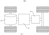
- Fig. 1 is a schematic structural diagram of a vehicle 1000 in some embodiments of the present application.
- the vehicle 1000 may be a fuel-powered vehicle, a gas-powered vehicle, or a new energy vehicle
- the new energy vehicle may be a battery electric vehicle, a hybrid electric vehicle, an extended-range vehicle, or the like.
- a battery 100 is disposed inside the vehicle 1000, and the battery 100 may be disposed at a bottom, head or tail of the vehicle 1000.
- a plurality of battery cells 20 may be disposed in the battery 100 inside the vehicle 1000.
- the battery 100 may be used for supplying power to the vehicle 1000, and for example, the battery 100 may be used as an operation power supply of the vehicle 1000.
- the vehicle 1000 may further include a controller 200 and a motor 300, and the controller 200 is used for controlling the battery 100 to supply power to the motor 300, for example, to satisfy a working power demand of the vehicle 1000 during startup, navigation and travelling.
- the battery 100 may be used not only as an operation power supply of the vehicle 1000, but also as a driving power supply of the vehicle 1000 to replace or partially replace fuel or natural gas to provide driving power for the vehicle 1000.
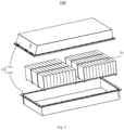
- Fig. 2 is a schematic structural diagram of a battery 100 in some embodiments of the present application.
- the battery 100 includes a casing 30, a battery cell 20, and a thermal management assembly 10.
- the casing 30 may be of a simple three-dimensional structure such as a single cuboid, cylinder or sphere, or a complex three-dimensional structure formed by combining simple three-dimensional structures such as cuboids, cylinders or spheres, which is not limited by the embodiments of the present application in this aspect.
- the material of the casing 30 may be alloy materials such as aluminum alloy and iron alloy, or polymer materials such as polycarbonate and polyisocyanurate foam plastic, or composite materials such as glass fiber combined with epoxy resin, which is not limited in the embodiments of the present application in this aspect.
- the casing 30 is used for accommodating the battery 100, and the casing 30 may be formed in various structures.
- the casing 30 may include a first casing portion 301 and a second casing portion 302, which cover and close each other, and define an accommodating space for accommodating the battery cell 20 together.
- the second casing portion 302 may be of a hollow structure with an open end, the first casing portion 301 is of a plate-like structure, and the first casing portion 301 covers and closes the open side of the second casing portion 302 to form the casing 30 with an accommodating space; or, each of the first casing portion 301 and the second casing portion 302 may be of a hollow structure with an open side, and the open side of the first casing portion 301 covers and closes the open side of the second casing portion 302 to form the casing 30 with an accommodating space.
- the first casing portion 301 and the second casing portion 302 may be in various shapes, such as in cylindrical or cuboid shapes.
- a sealing member such as a sealant or a sealing ring may be disposed between the first casing portion 301 and the second casing portion 302.
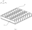
- Fig. 3 is a schematic diagram of assembly of the battery cell 20 and the thermal management assembly 10 in some embodiments of the present application.
- Fig. 4 is a schematic structural diagram of the thermal management assembly 10 in some embodiments of the present application. As shown in Fig. 3 and Fig. 4 , the thermal management assembly 10 includes a base plate 1 and a cover plate 2.
- Fig. 5 is a cross-sectional schematic diagram of the thermal management assembly 10 shown in Fig. 4 .
- Fig. 6 is an enlarged schematic diagram of region M in Fig. 5 .
- the cover plate 2 covers and closes the base plate 1 to form a flow channel A
- the flow channel A is adapted for accommodating a heat regulation medium
- the cover plate 2 includes a plurality of fins 21 and connecting portions 22 each connected with adjacent two fins 21, the plurality of fins 21 extend in a first direction and are spaced apart in a second direction, at least some of the plurality of fins 21 are formed as hollow structures each including a cavity A2, the flow channel A includes the cavity A2, and the connecting portion 22 and the corresponding adjacent two fins 21 form a placement slot B, where the first direction intersects with the second direction.
- a height direction of the battery cell 20 is the first direction, namely, a Z direction; a length direction is the second direction, namely, an X direction; and the first direction and the second direction are perpendicular to each other.
- first direction and the second direction may be considered perpendicular to each other.
- the first direction and the second direction may alternatively be other directions, and there may be other angles between them, which will not be described in the present application.
- other directions will be further defined in detail, which will not be described here.
- the fins 21 are of sheet-like structures, and all of fins 21 extend in the first direction Z, that is, a plurality of sheet-like structures extending in the first direction Z are connected to the cover plate 2 so as to protrude among battery cells 20 when the thermal management assembly 10 is assembled with the battery cells 20.
- the connecting portions 22, as a main body of the cover plate 2 are each connected between adjacent two fins 21. Since the fins 21 are spaced apart in the second direction X, the connecting portions 22 are each located in the spacing between adjacent two fins 21 to connect the adjacent fins 21 so as to form and enclose the placement slot B with the fins 21, which at least partially surrounds the battery cell 20 when the battery cell 20 is placed in the placement slot B.
- cavities A2 also extend in the first direction Z.
- the flow channel A is formed between the cover plate 2 and the base plate 1, and the flow channel A includes the cavities A2, that is, the heat regulation medium flows between the cover plate 2 and the base plate 1 and also within the cavities A2 of the fins 21.
- the heat regulation medium within the cavities A2 of the fins 21 and the heat regulation medium between the cover plate 2 and the base plate 1 will come into contact with the battery cells 20 through the fins 21 and the connecting portions 22 to achieve a heat regulation effect on the battery cells 20.
- the fins 21 are formed as hollow structures each including the cavity A2, and the heat regulation medium is introduced into the cavities A2 of the fins 21, which can achieve a better heat dissipation effect on the battery cells 20. Moreover, the fins 21 are of sheet-like structures, which occupy a small volume when protruding among the plurality of battery cells 20, so that the battery 100 can maintain a good energy density.
- the plurality of fins 21 may all include cavities A2 or merely some of the fines 21 include cavities A2. At least some of the plurality of fins 21 include the cavities A2, meaning that some of the fins 21 do not include cavities A2 while are formed as solid structures into which no heat regulation medium is introduced. In this case, the fins 21 can also transfer the heat of the battery to the heat regulation medium in the flow channel A through their ends connected to the cover plate 2, thereby achieving the thermal control effect to a certain degree.
- the base plate 1 includes a plurality of support portions 11, a channel A1 is formed between adjacent two support portions 11, and the flow channel A includes the channel A1.
- the cover plate 2 covers and closes the base plate 1, and the battery cells 20 are placed in the placement slots B of the cover plate 2.
- the base plate 1 includes the plurality of support portions 11.
- the support portions 11 are formed as raised strips extending from the base plate 1 in the first direction Z towards the cover plate 2, to provide support for the cover plate 2.
- the channel A1, formed between adjacent support portions 11, is a channel through which the heat regulation medium flows.
- the support portions 11 may be in contact with the cover plate 2 to support the cover plate 2, and in this case, gaps are formed between the cover plate 2 and other support portions 11 that are not in contact with the cover plate 2.
- the heat regulation medium may flow through the gaps, thereby increasing the contact area between the heat regulation medium and the cover plate 2 and improving the heat exchange rate between the thermal management assembly 10 and the battery cells 20.
- an orthographic projection of each fin 21 on the base plate 1 falls within a range of a corresponding channel A1.
- the flow channel A includes the cavity A2 inside the fin 21 and the channel A1, by making the orthographic projection of the fin 21 on the base plate 1 to fall within the range of the channel A1, that is, the fin 21 is located above the channel A1 in the first direction Z, it can be ensured that the channel A1 is in communication with the cavity A2.
- the orthographic projection of the fin 21 on the base plate 1 may partially overlap with the channel A1, or fall between two adjacent channels A1; in this case, the heat regulation medium may also be introduced into the cavity A2 of the fin 21, which is not limited by the embodiments of the present application in this aspect.
- an orthographic projection of the connecting portion 22 on the base plate 1 covers some of the support portions 11 and channels A1.
- the connecting portion 22 connects with adjacent fins 21, and since the fins 21 are spaced apart in the second direction X, the orthographic projection of the connecting portion 22 between the adjacent fins 21 on the base plate 1 covers the support portions 11 and the channels A1, so that the support portions 11 are at least arranged on two sides of each fin 21, so as to provide better support for the battery cell 20 placed on the connecting portion 22.
- an extension width of the connecting portion 22 may be greater than a sum of an extension width of the support portion 11 and an extension width of the channel A1, so that at least one support portion 11 is included below the connecting portion 22.
- At least some of a plurality of channels A1 are in communication with each other.
- At least some of the plurality of channels A1 are in communication with each other, so that the thermal management assembly 10 may have a plurality of flow channels A.
- the temperature of a plurality of groups of battery cells 20 can be controlled by controlling the temperature of the heat regulation medium in the plurality of flow channels A, so as to achieve thermal management on the battery 100.
- the thermal management assembly 10 further includes a medium inlet and a medium outlet disposed at two ends of the base plate 1 respectively and in communication with the flow channel A.
- the thermal management assembly 10 has only one set of medium inlet and medium outlet.
- the thermal management assembly 10 may have a corresponding number of medium inlets and medium outlets.
- the cover plate 2 includes snapping ends 23 at two opposite ends in the second direction X, and the snapping ends 23 are connected with the outermost support portions 11 of the base plate 1 in the second direction X in a snap-fit manner.
- the outermost support portions 11 of the base plate 1 in the second direction X may be regarded as edges of the base plate 1 in the second direction X, and by making the cover plate 2 to include the snapping ends 23 at two ends in the second direction X, the cover plate 2 and the base plate 1 can be connected to each other in the second direction X, thereby achieving a good sealing effect and preventing leakage of the heat regulation medium.
- the cover plate 2 may be connected to the base plate 1 by welding, bonding, or other manners that can achieve a sealing effect, which is not limited by the embodiments of the present application in this aspect.
- the cover plate 2 further includes connecting ends 24 located at two opposite ends in a third direction, the base plate 1 includes stop edges 12 opposite each other in the third direction, and the connecting ends 24 are connected to the stop edges 12 by welding.
- a width direction of the battery cell 20 is the third direction, namely, a Y direction, and the first direction, the second direction, and the third direction are perpendicular to each other. It should be understood that, when an angle among the first direction, the second direction, and the third direction is 85 to 95 degrees, the three directions may be considered perpendicular to each other.
- the first direction, the second direction, and the third direction may alternatively be other directions, which are not limited by the embodiments of the present application.
- two opposite ends of the cover plate 2 include connecting ends 24, and two opposite ends of the base plate 1 include stop edges 12, that is, the cover plate 2 and the base plate 1 are connected to each other in the third direction Y through the connecting ends 24 and the stop edges 12.
- the connecting ends 24 and the stop edges 12 are connected by welding, so that there is a relatively sealed structure between the cover plate 2 and the base plate 1, thereby preventing the heat regulation medium from leaking therefrom.
- the fin 21 includes two thermal conductive walls 211 extending in the first direction Z and opposite each other, the two thermal conductive walls 211 are spaced apart in the second direction X, and in the first direction Z, the two thermal conductive walls 211 are connected to the connecting portion 22 at one end and are connected to each other at the other end.
- the thermal conductive wall 211 is a wall, in contact with the battery cell 20, of the fin 21.
- the two thermal conductive walls 211 extend in the first direction Z and are spaced apart in the second direction X, and a distance is remained between them in the second direction X to form the cavity A2 in the fin 21.
- the thermal conductive walls 211 are connected to the connecting portion 22 at one end in the first direction Z, and are connected to each other at the other end, so that the fin 21 extends from the connecting portion 22 and is closed at the top.
- a connection position between the two thermal conductive walls 211 is rounded.
- connection position between the two thermal conductive walls 211 By making the connection position between the two thermal conductive walls 211 to be rounded, the thermal conductive walls 211 can have better bending performance, that is, can be deformed to a certain degree when the battery cell 20 expands, so as to adapt to the volume change of the battery cell 20 by compressing the volume of the cavity A2.
- the rounded connection position between the thermal conductive walls 211 can facilitate placement of the battery cell 20 into the placement slot B, and prevents the battery cell 20 from being scratched when being placed into the placement slot B.
- two ends of the fin 21 include sealing walls 212, and the sealing walls 212 are connected to the thermal conductive walls 211 and form and enclose the cavity A2 together with the thermal conductive walls 211.
- the sealing walls 212 Projections of the sealing walls 212 along the second direction X are consistent with the cavity A2 in shape, and the sealing walls 212 are connected to the two thermal conductive walls 211, so that the fin 21 is formed into a sealed hollow structure, that is, the sealing walls 212 and the two thermal conductive walls 211 form and enclose the cavity A2.
- the sealing walls 212 may be connected to the thermal conductive walls 211 by welding, bonding, or the like, as long as the sealing walls 212 and the thermal conductive walls 211 can be connected in a sealing manner, which are not limited by the embodiments of the present application in this aspect.
- a surface, in contact with the battery cell 20, of the thermal conductive wall 211 is coated with a thermal conductive adhesive.
- the thermal conductive adhesive is a colloid with good thermal conductivity, and by coating the thermal conductive wall 211 with the thermal conductive adhesive, the heat of the battery cell 20 can be better transferred to the thermal conductive wall 211 in the case that the thermal conductive wall 211 is in contact with the battery cell 20 and transferred to the heat regulation medium in the internal cavity A2 of the fin 21 through the thermal conductive wall 211, so that the thermal management assembly 10 has better heat regulation performance.
- the plurality of fins 21 are all formed as hollow structures each including a cavity A2, and the connecting portions 22 are integrally formed with the fins 21.
- connecting portions 22 By integrally forming the connecting portions 22 with the fins 21, it can avoid the poor sealing, which may lead to leakage of the heat regulation medium, from occurring when respective connecting portions 22 are connected to respective fins 21.
- the cover plate 2 is a stamping component with fins 21 formed by stamping an entire plate at predetermined positions.
- the cover plate 2 is formed by stamping the entire plate, which can facilitate manufacturing of the thermal management assembly 10, with a relatively low cost.
- the sealing walls 212 are connected between the two thermal conductive walls 211 of respective fins 21, so that the fins 21 are formed into hollow structures including the cavities A2.
- the cover plate 2 is formed by stamping an aluminum sheet, and since the aluminum sheet has a good thermal conductivity, it can well transfer the heat of the battery cells 20 to the heat regulation medium, thereby achieving thermal management on the battery cells 20. Also, the aluminum sheet itself has elasticity to a certain degree, and may be deformed to a certain degree along with the expansion of the battery cells 20, so that the overall structure of the battery cells 20 is more stable.
- one or more battery cells 20 may be disposed in the casing 30.
- at least one battery cell 20 is placed in each placement slot B.
- a plurality of battery cells 20 may be connected in series, in parallel, or in hybrid.
- the hybrid connection refers to a combination of series connection and parallel connection in the plurality of battery cells 20.
- the plurality of battery cells 20 may be directly connected in series, in parallel, or in hybrid together, and then the integrity formed by the plurality of battery cells 20 is accommodated in the casing 30.
- the plurality of battery cells 20 may be first connected in series, in parallel, or in hybrid to form a battery 100, and then a plurality of batteries 100 are connected in series, in parallel, or in hybrid to form an integrity, which is accommodated in the casing 30.
- the plurality of battery cells 20 in the battery 100 may be electrically connected through a busbar to achieve the parallel, series, or hybrid connection of the plurality of battery cells 20 in the battery 100.
- an extension height of the fin 21 is not greater than that of the battery cell 20.
- the extension height of the fin 21 matches that of the battery cell 20, which can prevent the fin 21 from extending beyond the battery cell 20 to interfere with the busbar that may be disposed at a top end of the battery cell 20, and prevent the fin 21 from affecting the electrical connection between the battery cells 20.
- an extension length of the fin 21 is not less than that of at least one battery cell 20.
- the extension length of the fin 21 may merely match the extension length of some of the battery cells 20 in the third direction Y.
- the fin 21 may be in contact with some of the battery cells 20 in the third direction Y, the thermal management effect on the battery 100 still can be achieved to a certain degree, and the embodiments of the present application are not limited in this aspect.
- a spacing width between adjacent two fins 21 is not less than an extension width of the battery cell 20.
- the spacing width between the adjacent fins 21 is not less than the extension width of the battery cell 20, so that the battery cell 20 can be placed in the placement slot B formed by adjacent two fins 21 and the corresponding connecting portion 22.
- the spacing width between the adjacent fins 21 should not be greater than the extension width of the battery cell 20 too much, so as to avoid unnecessary bump caused by the shaking of the battery cell 20 between them.
- a plurality of battery cells 20 may be arranged between adjacent two fins 21.
- two groups of battery cells 20 may be placed between the adjacent two fins 21. This setting can be determined according to specific production needs, and the embodiments of the present application do not limit this.
- the battery 100 may include a plurality of thermal management assemblies 10.
- two thermal management assemblies 10 may be opposite each other in the first direction Z, the fins 21 of one thermal management assembly 10 protrudes into the placement slots B of the other thermal management assembly 10, the fins 21 of the two thermal management assemblies 10 are arranged alternately, and the battery cells 20 are disposed between adjacent fins 21.
- the two thermal management assemblies 10 may achieve different thermal management effects on the battery cells 20, thereby avoiding multiple times of heating or cooling of the heat regulation medium, or avoiding introduction of the heat regulation medium into the same thermal management assembly 10 for multiple times.
- Fig. 7 is a schematic diagram of an internal structure of a battery cell 20 in some embodiments of the present application.
- the battery cell 20 refers to a minimum unit that constitutes the battery 100.
- the battery cell 20 further includes an end cover 201, a shell 202, an electrode assembly 203, and other functional components.
- the end cover 201 refers to a component that covers and closes an opening of the shell 202 to isolate an internal environment of the battery cell 20 from an external environment.
- a shape of the end cover 201 may adapt to that of the shell 202 to match the shell 202.
- the end cover 201 may be made of a material with certain hardness and strength (such as aluminum alloy); in this case, the end cover 201 is less prone to deformation when being squeezed and collided, so that the battery cell 20 can have higher structural strength and its safety can be improved.
- Functional components such as an electrode terminal and an explosion-proof valve are disposed on the end cover 201.
- the electrode terminal may be used for being electrically connected to the electrode assembly 203 to output or input electrical energy of the battery cell 20.
- a pressure relief mechanism may be further disposed on the end cover 201 to release internal pressure when the internal pressure or temperature of the battery cell 20 reaches a threshold.
- a material of the end cover 201 may be various, such as copper, iron, aluminum, stainless steel, aluminum alloy, or plastic, and is not specially limited in the embodiments of the present application.
- an insulating member may be further disposed on an inner side of the end cover 201, and the insulating member may be used for isolating electrical connection plate members inside the shell 202 from the end cover 201 to reduce a risk of short-circuiting.
- the insulating member may be made of plastic, rubber, or the like.
- the shell 202 is a component matching the end cover 201 to form the internal environment of the battery cell 20, where the formed internal environment may be used for accommodating the electrode assembly 203, an electrolyte (not shown), and other components.
- the shell 202 and the end cover 201 may be independent components, the shell 202 may be provided with an opening, and the end cover 201 covers and closes the opening to form the internal environment of the battery cell 20.
- the end cover 201 and the shell 202 may be integrally formed.
- the end cover 201 and the shell 202 may form a common connection surface before other components are assembled into the shell, and when the interior of the shell 202 need to be sealed, the end cover 201 covers and closes the shell 202.
- the shell 202 may be in various shapes and sizes, such as cuboid, cylinder, or hexagonal prism. Specifically, the shape of the shell 202 may be determined according to a specific shape and size of the electrode assembly 203.
- a material of the shell 202 may be various, such as copper, iron, aluminum, stainless steel, aluminum alloy, or plastic, which is not specially limited in the embodiments of the present application.
- the electrode assembly 203 is a component that undergoes electrochemical reactions in the battery cell 20.
- the shell 202 may contain one or more electrode assemblies 203.
- the electrode assembly 203 is mainly formed by winding or stacking a positive electrode plate and a negative electrode plate, and a separator is generally disposed between the positive electrode plate and the negative electrode plate. Portions of the positive electrode plate and the negative electrode plate that include active materials constitute a main body of the electrode assembly 203, while portions of the positive electrode plate and the negative electrode plate that do not include active materials constitute respective tabs.
- the positive tab and the negative tab may be located at one end of the main body or at two ends of the main body respectively. In charging or discharging process of the battery 100, the positive and negative active materials react with the electrolyte, and the tabs are connected to electrode terminals to form a current circuit.
- the thermal management assembly 10 is provided with a base plate 1 and a cover plate 2, the cover plate 2 covers and closes the base plate 1 to form a flow channel A, the flow channel A is adapted for accommodating a heat regulation medium, the cover plate 2 includes a plurality of fins 21 and connecting portions 22 each connected to adjacent two fins 21, the plurality of fins 21 extend in a first direction and are spaced apart in a second direction, at least some of the plurality of fins 21 are formed as hollow structures each including a cavity A2, the flow channel A includes the cavity A2, and the connecting portion 22 and corresponding adjacent two fins 21 form a placement slot B for placing a battery cell 20 of a battery 100.
- the thermal management assembly 10 of the embodiments of the present application can achieve a good thermal management effect on the battery 100.
Landscapes
- Engineering & Computer Science (AREA)
- Manufacturing & Machinery (AREA)
- Chemical & Material Sciences (AREA)
- Chemical Kinetics & Catalysis (AREA)
- Electrochemistry (AREA)
- General Chemical & Material Sciences (AREA)
- Secondary Cells (AREA)
- Battery Mounting, Suspending (AREA)
Abstract
Description
- The present application claims priority to
Chinese Patent Application No. 202221932075.X, entitled "THERMAL MANAGEMENT ASSEMBLY, BATTERY, AND ELECTRIC APPARATUS" and filed on July 18, 2022 - The present application belongs to the field of battery technologies, and in particular, relates to a thermal management assembly, a battery, and an electric apparatus.
- Batteries are widely used in electric apparatuses, such as mobile phones, laptops, electric scooters, electric cars, electric airplanes, electric ships, electric toy cars, electric toy ships, electric toy planes, and electric tools.
- In the development of battery technologies, effective thermal management on batteries is an important research direction in the battery technologies.
- Embodiments of the present application provide a thermal management assembly, a battery, and an electric apparatus, which can effectively meet thermal management requirements of the battery.
- In a first aspect, an embodiment of the present application provides a thermal management assembly, including a base plate and a cover plate. The cover plate covers and closes the base plate to form a flow channel, the flow channel is adapted for accommodating a heat regulation medium, the cover plate includes a plurality of fins and connecting portions each connected to adjacent two fins, the plurality of fins extend in a first direction and are spaced apart in a second direction, at least some of the plurality of fins are formed as hollow structures each including a cavity, the flow channel includes the cavity, and each connecting portion and corresponding adjacent two fins form a placement slot, where the first direction intersects with the second direction.
- According to the thermal management assembly in the embodiment of the present application, the cover plate includes a plurality of fins and connecting portions each connected to adjacent two fins, the fins are formed as hollow structures each including a cavity, the cavity is included by a flow channel formed by the cover plate and the base plate, and the heat regulation medium flows through the flow channel, so that the flow channel conducts heat of a battery cell placed in a placement slot formed by the connecting portion and corresponding adjacent two fins. The fins each with the cavity can balance the temperature of the battery cell through the internal heat regulation medium, are simple in structure, small in size, and easy to be processed, and can ensure an energy density of the battery.
- In some embodiments, the base plate includes a plurality of support portions, a channel is formed between adjacent two support portions, and the flow channel includes the channel.
- In the foregoing technical solution, the support portions can support the cover plate and prevent unnecessary deformation of the cover plate from affecting the thermal management effect of the thermal management assembly.
- In some embodiments, in at least some of the fins, an orthographic projection of each fin on the base plate falls within a range of a corresponding channel to ensure that the channel is in communication with the cavity.
- In some embodiments, an orthographic projection of the connecting portion on the base plate covers some of the support portions and channels.
- In the foregoing technical solution, the support portions are arranged at least on two sides of each fin, thereby providing better support for the battery cells placed on the connecting portions.
- In some embodiments, at least some of a plurality of channels are in communication with each other.
- In the foregoing technical solution, the thermal management assembly can control the temperature of different battery cells by controlling the temperature of the heat regulation medium in the plurality of channels.
- In some embodiments, the cover plate includes snapping ends located at two opposite ends in the second direction, and the snapping ends are connected with the outermost support portions of the base plate in the second direction in a snap-fit manner, so that the cover plate and the base plate are connected to each other in the second direction, thereby achieving a good sealing effect and preventing leakage of the heat regulation medium.
- In some embodiments, the cover plate further includes connecting ends located at two opposite ends in a third direction, the base plate includes stop edges opposite each other in the third direction, and the connecting ends are connected to the stop edges by welding, so that a relatively sealed structure is formed between the cover plate and the base plate to prevent the leakage of the heat regulation media therefrom.
- In some embodiments, the fin includes two thermal conductive walls extending in the first direction and opposite each other, the two thermal conductive walls are spaced apart in the second direction, and in the first direction, the two thermal conductive walls are connected to the connecting portion at one end and are connected to each other at the other end, so as to form the cavity in the fin.
- In some embodiments, a connection position between the two thermal conductive walls is rounded.
- In the foregoing technical solution, the thermal conductive walls are enabled to have better bending performance.
- In some embodiments, in the third direction, two ends of the fin include sealing walls, and the sealing walls are connected to the thermal conductive walls and form and enclose the cavity together with the thermal conductive walls, so that the fin is of a hollow structure.
- In some embodiments, a surface, in contact with the battery cell, of the thermal conductive wall is coated with a thermal conductive adhesive, so that the thermal management assembly has better heat regulation performance.
- In some embodiments, the plurality of fins are all formed as hollow structures each including a cavity, and the connecting portions are integrally formed with the fins.
- In the foregoing technical solution, it can avoid the poor sealing occurring when respective connecting portions are connected to respective fins, which may lead to leakage of the heat regulation medium.
- In some embodiments, the cover plate is a stamped component with fins formed by stamping an entire plate at predetermined positions, which can facilitate manufacturing of the thermal management assembly.
- In a second aspect, an embodiment of the present application provides a battery, including the above thermal management assembly and battery cells. At least one battery cell is placed in each placement slot.
- In some embodiments, in the first direction, an extension height of the fin is not greater than that of the battery cell.
- In the foregoing technical solution, the fins can be prevented from affecting the electrical connection between the battery cells.
- In some embodiments, in the third direction, an extension length of the fin is not less than that of at least one of the battery cells.
- In some embodiments, in the second direction, a spacing width between adjacent two fins is not less than an extension width of the battery cell.
- In the foregoing technical solution, the battery cell can be placed in the placement slot to avoid unnecessary bump.
- In a third aspect, an embodiment of the present application provides an electric apparatus, including the battery as described above, where the battery is adapted for providing electrical energy.
- In order to explain the technical solutions of the embodiments of the present application more clearly, the accompanying drawings required for use in the embodiments of the present application will be briefly introduced below. Apparently, the accompanying drawings described below show only some embodiments of the present application. Those of ordinary skill in the art can derive other drawings based on the accompanying drawings without any creative effort.
-
Fig. 1 is a schematic structural diagram of a vehicle in some embodiments of the present application; -
Fig. 2 is a schematic structural diagram of a battery in some embodiments of the present application; -
Fig. 3 is a schematic diagram of assembly of battery cells and a thermal management assembly in some embodiments of the present application; -
Fig. 4 is a schematic structural diagram of the thermal management assembly in some embodiments of the present application; -
Fig. 5 is a cross-sectional schematic diagram of the thermal management assembly shown inFig. 4 ; -
Fig. 6 is an enlarged schematic diagram of region M inFig. 5 ; and -
Fig. 7 is a schematic structural diagram of a battery cell in some embodiments of the present application. - Reference numerals of specific implementations are as follows:
- 1000. Vehicle; 100. Battery; 200. Controller; 300. Motor; 30. Casing; 301. First casing portion; 302. Second casing portion; 20. Battery cell; 201. End cover; 202. Shell; 203. Electrode assembly;
- 10. Thermal management assembly; 1. Base plate; 11. Support portion; 12. Stop edge; 2. Cover plate; 21. Fin; 211. Thermal conductive wall; 212. Sealing wall; 22. Connecting portion; 23. Snapping end; 24. Connecting end; A. Flow channel; A1. Channel; A2. Cavity; B. Placement slot;
- Z. First direction; X. Second direction; Y. Third direction.
- To make the objectives, technical solutions and advantages of the embodiments of the present application clearer, the technical solutions in the embodiments of the present application will be described clearly below with reference to the accompanying drawings in the embodiments of the present application. Apparently, the described embodiments are some but not all of the embodiments of the present application. All other embodiments obtained by the person skilled in the art based on the embodiments of the present application without creative efforts shall fall within the protection scope of the present application.
- Unless otherwise defined, all technical and scientific terms used in the present application have the same meanings as those commonly understood by technical personnel in the technical field of the present application; the terms used in the specification of the present application are only for the purpose of describing specific embodiments and are not intended to limit the present application; and the terms "include" and "have" and any variations thereof in the specification, claims, the above description of the accompanying drawings of the present application are intended to cover non-exclusive inclusion. The terms "first", "second", and the like in the specification, claims or the above description of accompanying drawings of the present application are adapted to distinguish different objects, rather than to describe specific sequences or primary and secondary relationships.
- The "embodiment" mentioned in the present application means that specific features, structures or characteristics described in conjunction with the embodiment may be included in at least one embodiment of the present application. This phrase at various locations in the specification does not necessarily refer to the same embodiment, or an independent or alternative embodiment exclusive of another embodiment.
- In the description of the present application, it should be noted that, unless otherwise specified and defined, the terms "mount", "connect", "couple", and "attach" should be broadly understood, for example, the terms may refer to a fixed connection, a detachable connection, or an integral connection, may refer to a direct connection, a connection through a medium, or a communication of interiors of two elements. Person skilled in the art may understand the specific meanings of the above terms in the present application according to specific circumstances.
- The term "and/or" in the present application refers to merely an association relationship for describing associated objects, and represents that three relationships may exist. For example, A and/or B may represent the following three cases: A exists alone, both A and B exist, and B exists alone. In addition, the character "/" in the present application generally indicates an "or" relationship between the associated objects.
- In the embodiments of the present application, the same reference numerals represent the same components, and for simplicity, detailed descriptions of the same components are omitted in different embodiments. It should be understood that, in the embodiments of the present application shown in the accompanying drawings, dimensions of various components and integrated apparatuses, such as thickness, length, and width, are only illustrative and should not constitute any limitations on the present application.
- In the present application, "a plurality of" means two or more (including two).
- The term "parallel" in the present application includes not only situations of absolute parallelism, but also situations of general parallelism recognized in engineering. Meanwhile, the term "perpendicular" further includes not only situations of absolute perpendicularity, but also situations of general perpendicularity recognized in engineering.
- In the present application, the battery cells may include lithium-ion secondary battery cells, lithium-ion primary battery cells, lithium-sulfur battery cells, sodium lithium-ion battery cells, sodium-ion battery cells, magnesium-ion battery cells, or the like, which are not limited by the embodiments of the present application in this aspect. The battery cells may be cylindrical, flat, cuboid, or in other shapes, which are not limited by the embodiments of the present application in this aspect either.
- The battery mentioned in the embodiments of the present application refers to a single physical module that includes one or more battery cells to provide higher voltage and capacity. The battery generally further includes a casing for packaging one or more battery cells. The casing may prevent liquid or other foreign matters from affecting charging or discharging of the battery cells.
- The battery cell includes an electrode assembly and an electrolyte, and the electrode assembly includes a positive electrode plate, a negative electrode plate, and a separator. The battery cell mainly relies on migration of metal ions between the positive electrode plate and the negative electrode plate to work. The positive electrode plate includes a positive current collector and a positive active material layer applied on a surface of the positive current collector. Taking a lithium-ion battery as an example, a material for the positive current collector may be aluminum, and the positive active material layer includes a positive active material, which may be lithium cobalt oxide, lithium iron phosphate, ternary lithium, lithium manganate, or the like. The negative electrode plate includes a negative current collector and a negative active material layer applied on a surface of the negative current collector. A material for the negative current collector may be copper, and the negative active material layer includes a negative active material, which may be carbon, silicon, or the like. A material for the separator may be polypropylene (PP), polyethylene (PE), or the like.
- At present, in view of the development of the market situation, the application of power batteries is increasingly widespread. The power batteries are not only applied in energy storage power systems such as hydropower, firepower, wind power, and solar power plants, but also widely applied in electric transportation vehicles such as electric bicycles, electric motorcycles, and electric vehicles, as well as in various fields such as military equipment and aerospace. With the continuous expansion of the application fields of power batteries, their market demand is also increasing.
- In related technologies, a thermal management assembly is often disposed at a bottom of the battery casing, bottoms of the battery cells are in contact with the thermal management assembly, a heat regulation medium flows through the thermal management assembly, the thermal management assembly includes fins that extend among a plurality of battery cells, and the fins are supported by a metal material that can conduct heat so as to transfer the heat of the battery cells to the heat regulation medium, thereby achieving thermal management effects. However, the inventor noticed that, in the above configuration, the fins are made of a single-layer aluminum plate, poor sealing is prone to occur at positions where the fins are inserted into a cover plate, and only roots of the fins are in contact with the heat regulation medium, so the heat dissipation efficiency is relatively low.
- In view of this, an embodiment of the present application provides a thermal management assembly, where a cover plate includes a plurality of fins and connecting portions each connected to adjacent two fins, the fins are formed as hollow structures each including a cavity, the cavity is included by a flow channel formed by the cover plate and the base plate, and a heat regulation medium flows through the flow channel, so that the flow channel conducts heat of a battery cell placed in a placement slot formed by the connecting portion and the corresponding adjacent two fins. The fins with the cavities can balance the temperature of battery cells through the internal heat regulation medium, are simple in structure, small in size, and easy to be processed, and can ensure an energy density of the battery.
- The technical solutions described in the embodiments of the present application are applicable to a thermal management assembly, a battery using the thermal management assembly, and an electric apparatus powered by a battery.
- The electric apparatus may be a vehicle, a mobile phone, a portable device, a notebook computer, a ship, a spacecraft, an electric toy, an electric tool, or the like. The vehicle may be a fuel-powered vehicle, a gas-powered vehicle, or a new energy vehicle. The new energy vehicle may be a battery electric vehicle, a hybrid electric vehicle, an extended-range vehicle, or the like. The spacecraft includes an airplane, a rocket, a space shuttle, a spaceship, or the like. The electric toy includes a fixed or mobile electric toy, such as a game console, an electric car toy, an electric ship toy, or an electric aircraft toy. The electric tool includes a metal cutting electric tool, a grinding electric tool, an assembly electric tool, or a railway electric tool, such as an electric drill, an electric grinder, an electric wrench, an electric screwdriver, an electric hammer, an impact electric drill, a concrete vibrator, or an electric planer. The embodiments of the present application do not impose special restrictions on the foregoing electric apparatus.
- It should be understood that the technical solutions described in the embodiments of the present application are not only applicable to the electric apparatuses described above, but for the sake of simplicity, the following embodiments are all illustrated using a
vehicle 1000 as an example. -
Fig. 1 is a schematic structural diagram of avehicle 1000 in some embodiments of the present application. As shown inFig. 1 , thevehicle 1000 may be a fuel-powered vehicle, a gas-powered vehicle, or a new energy vehicle, and the new energy vehicle may be a battery electric vehicle, a hybrid electric vehicle, an extended-range vehicle, or the like. Abattery 100 is disposed inside thevehicle 1000, and thebattery 100 may be disposed at a bottom, head or tail of thevehicle 1000. - In order to meet different power usage requirements, a plurality of
battery cells 20 may be disposed in thebattery 100 inside thevehicle 1000. Thebattery 100 may be used for supplying power to thevehicle 1000, and for example, thebattery 100 may be used as an operation power supply of thevehicle 1000. Thevehicle 1000 may further include acontroller 200 and amotor 300, and thecontroller 200 is used for controlling thebattery 100 to supply power to themotor 300, for example, to satisfy a working power demand of thevehicle 1000 during startup, navigation and travelling. In some embodiments of the present application, thebattery 100 may be used not only as an operation power supply of thevehicle 1000, but also as a driving power supply of thevehicle 1000 to replace or partially replace fuel or natural gas to provide driving power for thevehicle 1000. -
Fig. 2 is a schematic structural diagram of abattery 100 in some embodiments of the present application. As shown inFig. 2 , thebattery 100 includes acasing 30, abattery cell 20, and athermal management assembly 10. - The
casing 30 may be of a simple three-dimensional structure such as a single cuboid, cylinder or sphere, or a complex three-dimensional structure formed by combining simple three-dimensional structures such as cuboids, cylinders or spheres, which is not limited by the embodiments of the present application in this aspect. The material of thecasing 30 may be alloy materials such as aluminum alloy and iron alloy, or polymer materials such as polycarbonate and polyisocyanurate foam plastic, or composite materials such as glass fiber combined with epoxy resin, which is not limited in the embodiments of the present application in this aspect. - The
casing 30 is used for accommodating thebattery 100, and thecasing 30 may be formed in various structures. In some embodiments, thecasing 30 may include afirst casing portion 301 and asecond casing portion 302, which cover and close each other, and define an accommodating space for accommodating thebattery cell 20 together. Thesecond casing portion 302 may be of a hollow structure with an open end, thefirst casing portion 301 is of a plate-like structure, and thefirst casing portion 301 covers and closes the open side of thesecond casing portion 302 to form thecasing 30 with an accommodating space; or, each of thefirst casing portion 301 and thesecond casing portion 302 may be of a hollow structure with an open side, and the open side of thefirst casing portion 301 covers and closes the open side of thesecond casing portion 302 to form thecasing 30 with an accommodating space. Thefirst casing portion 301 and thesecond casing portion 302 may be in various shapes, such as in cylindrical or cuboid shapes. - To improve the sealing performance after the
first casing portion 301 is connected to thesecond casing portion 302, a sealing member such as a sealant or a sealing ring may be disposed between thefirst casing portion 301 and thesecond casing portion 302. -
Fig. 3 is a schematic diagram of assembly of thebattery cell 20 and thethermal management assembly 10 in some embodiments of the present application.Fig. 4 is a schematic structural diagram of thethermal management assembly 10 in some embodiments of the present application. As shown inFig. 3 andFig. 4 , thethermal management assembly 10 includes a base plate 1 and acover plate 2. -
Fig. 5 is a cross-sectional schematic diagram of thethermal management assembly 10 shown inFig. 4 .Fig. 6 is an enlarged schematic diagram of region M inFig. 5 . As shown inFigs. 3 ,4 ,5 , and6 , in some embodiments of the present application, thecover plate 2 covers and closes the base plate 1 to form a flow channel A, the flow channel A is adapted for accommodating a heat regulation medium, thecover plate 2 includes a plurality offins 21 and connectingportions 22 each connected with adjacent twofins 21, the plurality offins 21 extend in a first direction and are spaced apart in a second direction, at least some of the plurality offins 21 are formed as hollow structures each including a cavity A2, the flow channel A includes the cavity A2, and the connectingportion 22 and the corresponding adjacent twofins 21 form a placement slot B, where the first direction intersects with the second direction. - For ease of description, in the embodiments of the present application, a height direction of the
battery cell 20 is the first direction, namely, a Z direction; a length direction is the second direction, namely, an X direction; and the first direction and the second direction are perpendicular to each other. It should be understood that, when an angle between the first direction and the second direction is 85 to 95 degrees, the first direction and the second direction may be considered perpendicular to each other. The first direction and the second direction may alternatively be other directions, and there may be other angles between them, which will not be described in the present application. In order to indicate other factors of thethermal management assembly 10 in the following description, other directions will be further defined in detail, which will not be described here. - The
fins 21 are of sheet-like structures, and all offins 21 extend in the first direction Z, that is, a plurality of sheet-like structures extending in the first direction Z are connected to thecover plate 2 so as to protrude amongbattery cells 20 when thethermal management assembly 10 is assembled with thebattery cells 20. The connectingportions 22, as a main body of thecover plate 2, are each connected between adjacent twofins 21. Since thefins 21 are spaced apart in the second direction X, the connectingportions 22 are each located in the spacing between adjacent twofins 21 to connect theadjacent fins 21 so as to form and enclose the placement slot B with thefins 21, which at least partially surrounds thebattery cell 20 when thebattery cell 20 is placed in the placement slot B. - Within the
fins 21 extending in the first direction Z, cavities A2 also extend in the first direction Z. The flow channel A is formed between thecover plate 2 and the base plate 1, and the flow channel A includes the cavities A2, that is, the heat regulation medium flows between thecover plate 2 and the base plate 1 and also within the cavities A2 of thefins 21. When thebattery cells 20 are placed in placement slots B, the heat regulation medium within the cavities A2 of thefins 21 and the heat regulation medium between thecover plate 2 and the base plate 1 will come into contact with thebattery cells 20 through thefins 21 and the connectingportions 22 to achieve a heat regulation effect on thebattery cells 20. - The
fins 21 are formed as hollow structures each including the cavity A2, and the heat regulation medium is introduced into the cavities A2 of thefins 21, which can achieve a better heat dissipation effect on thebattery cells 20. Moreover, thefins 21 are of sheet-like structures, which occupy a small volume when protruding among the plurality ofbattery cells 20, so that thebattery 100 can maintain a good energy density. - Optionally, the plurality of
fins 21 may all include cavities A2 or merely some of thefines 21 include cavities A2. At least some of the plurality offins 21 include the cavities A2, meaning that some of thefins 21 do not include cavities A2 while are formed as solid structures into which no heat regulation medium is introduced. In this case, thefins 21 can also transfer the heat of the battery to the heat regulation medium in the flow channel A through their ends connected to thecover plate 2, thereby achieving the thermal control effect to a certain degree. - In some embodiments of the present application, the base plate 1 includes a plurality of
support portions 11, a channel A1 is formed between adjacent twosupport portions 11, and the flow channel A includes the channel A1. - The
cover plate 2 covers and closes the base plate 1, and thebattery cells 20 are placed in the placement slots B of thecover plate 2. To prevent unnecessary deformation of thecover plate 2 from affecting the thermal management effect, the base plate 1 includes the plurality ofsupport portions 11. Thesupport portions 11 are formed as raised strips extending from the base plate 1 in the first direction Z towards thecover plate 2, to provide support for thecover plate 2. - The channel A1, formed between
adjacent support portions 11, is a channel through which the heat regulation medium flows. Optionally, merely some of thesupport portions 11 may be in contact with thecover plate 2 to support thecover plate 2, and in this case, gaps are formed between thecover plate 2 andother support portions 11 that are not in contact with thecover plate 2. The heat regulation medium may flow through the gaps, thereby increasing the contact area between the heat regulation medium and thecover plate 2 and improving the heat exchange rate between thethermal management assembly 10 and thebattery cells 20. - In some embodiments of the present application, in at least some of the
fins 21, an orthographic projection of eachfin 21 on the base plate 1 falls within a range of a corresponding channel A1. - Since the flow channel A includes the cavity A2 inside the
fin 21 and the channel A1, by making the orthographic projection of thefin 21 on the base plate 1 to fall within the range of the channel A1, that is, thefin 21 is located above the channel A1 in the first direction Z, it can be ensured that the channel A1 is in communication with the cavity A2. - Optionally, the orthographic projection of the
fin 21 on the base plate 1 may partially overlap with the channel A1, or fall between two adjacent channels A1; in this case, the heat regulation medium may also be introduced into the cavity A2 of thefin 21, which is not limited by the embodiments of the present application in this aspect. - In some embodiments of the present application, an orthographic projection of the connecting
portion 22 on the base plate 1 covers some of thesupport portions 11 and channels A1. - The connecting
portion 22 connects withadjacent fins 21, and since thefins 21 are spaced apart in the second direction X, the orthographic projection of the connectingportion 22 between theadjacent fins 21 on the base plate 1 covers thesupport portions 11 and the channels A1, so that thesupport portions 11 are at least arranged on two sides of eachfin 21, so as to provide better support for thebattery cell 20 placed on the connectingportion 22. - Optionally, in the second direction X, an extension width of the connecting
portion 22 may be greater than a sum of an extension width of thesupport portion 11 and an extension width of the channel A1, so that at least onesupport portion 11 is included below the connectingportion 22. - In some embodiments of the present application, at least some of a plurality of channels A1 are in communication with each other.
- At least some of the plurality of channels A1 are in communication with each other, so that the
thermal management assembly 10 may have a plurality of flow channels A. The temperature of a plurality of groups ofbattery cells 20 can be controlled by controlling the temperature of the heat regulation medium in the plurality of flow channels A, so as to achieve thermal management on thebattery 100. - Optionally, the
thermal management assembly 10 further includes a medium inlet and a medium outlet disposed at two ends of the base plate 1 respectively and in communication with the flow channel A. In a case that the plurality of channels A1 are in communication with each other, thethermal management assembly 10 has only one set of medium inlet and medium outlet. In a case that merely some of the channels A1 are in communication with each other, thethermal management assembly 10 may have a corresponding number of medium inlets and medium outlets. - In some embodiments of the present application, the
cover plate 2 includes snapping ends 23 at two opposite ends in the second direction X, and the snapping ends 23 are connected with theoutermost support portions 11 of the base plate 1 in the second direction X in a snap-fit manner. - The
outermost support portions 11 of the base plate 1 in the second direction X may be regarded as edges of the base plate 1 in the second direction X, and by making thecover plate 2 to include the snapping ends 23 at two ends in the second direction X, thecover plate 2 and the base plate 1 can be connected to each other in the second direction X, thereby achieving a good sealing effect and preventing leakage of the heat regulation medium. - Optionally, the
cover plate 2 may be connected to the base plate 1 by welding, bonding, or other manners that can achieve a sealing effect, which is not limited by the embodiments of the present application in this aspect. - In some embodiments of the present application, the
cover plate 2 further includes connecting ends 24 located at two opposite ends in a third direction, the base plate 1 includes stop edges 12 opposite each other in the third direction, and the connecting ends 24 are connected to the stop edges 12 by welding. - For ease of description, in the embodiments of the present application, a width direction of the
battery cell 20 is the third direction, namely, a Y direction, and the first direction, the second direction, and the third direction are perpendicular to each other. It should be understood that, when an angle among the first direction, the second direction, and the third direction is 85 to 95 degrees, the three directions may be considered perpendicular to each other. The first direction, the second direction, and the third direction may alternatively be other directions, which are not limited by the embodiments of the present application. - In the third direction Y, two opposite ends of the
cover plate 2 include connecting ends 24, and two opposite ends of the base plate 1 include stop edges 12, that is, thecover plate 2 and the base plate 1 are connected to each other in the third direction Y through the connecting ends 24 and the stop edges 12. The connecting ends 24 and the stop edges 12 are connected by welding, so that there is a relatively sealed structure between thecover plate 2 and the base plate 1, thereby preventing the heat regulation medium from leaking therefrom. - In some embodiments of the present application, the
fin 21 includes two thermalconductive walls 211 extending in the first direction Z and opposite each other, the two thermalconductive walls 211 are spaced apart in the second direction X, and in the first direction Z, the two thermalconductive walls 211 are connected to the connectingportion 22 at one end and are connected to each other at the other end. - The thermal
conductive wall 211 is a wall, in contact with thebattery cell 20, of thefin 21. The two thermalconductive walls 211 extend in the first direction Z and are spaced apart in the second direction X, and a distance is remained between them in the second direction X to form the cavity A2 in thefin 21. The thermalconductive walls 211 are connected to the connectingportion 22 at one end in the first direction Z, and are connected to each other at the other end, so that thefin 21 extends from the connectingportion 22 and is closed at the top. - In some embodiments of the present application, a connection position between the two thermal
conductive walls 211 is rounded. - By making the connection position between the two thermal
conductive walls 211 to be rounded, the thermalconductive walls 211 can have better bending performance, that is, can be deformed to a certain degree when thebattery cell 20 expands, so as to adapt to the volume change of thebattery cell 20 by compressing the volume of the cavity A2. In addition, the rounded connection position between the thermalconductive walls 211 can facilitate placement of thebattery cell 20 into the placement slot B, and prevents thebattery cell 20 from being scratched when being placed into the placement slot B. - In some embodiments of the present application, in the third direction Y, two ends of the
fin 21 include sealingwalls 212, and the sealingwalls 212 are connected to the thermalconductive walls 211 and form and enclose the cavity A2 together with the thermalconductive walls 211. - Projections of the sealing
walls 212 along the second direction X are consistent with the cavity A2 in shape, and the sealingwalls 212 are connected to the two thermalconductive walls 211, so that thefin 21 is formed into a sealed hollow structure, that is, the sealingwalls 212 and the two thermalconductive walls 211 form and enclose the cavity A2. Optionally, the sealingwalls 212 may be connected to the thermalconductive walls 211 by welding, bonding, or the like, as long as the sealingwalls 212 and the thermalconductive walls 211 can be connected in a sealing manner, which are not limited by the embodiments of the present application in this aspect. - In some embodiments of the present application, a surface, in contact with the
battery cell 20, of the thermalconductive wall 211 is coated with a thermal conductive adhesive. - The thermal conductive adhesive is a colloid with good thermal conductivity, and by coating the thermal
conductive wall 211 with the thermal conductive adhesive, the heat of thebattery cell 20 can be better transferred to the thermalconductive wall 211 in the case that the thermalconductive wall 211 is in contact with thebattery cell 20 and transferred to the heat regulation medium in the internal cavity A2 of thefin 21 through the thermalconductive wall 211, so that thethermal management assembly 10 has better heat regulation performance. - In some embodiments of the present application, the plurality of
fins 21 are all formed as hollow structures each including a cavity A2, and the connectingportions 22 are integrally formed with thefins 21. - By integrally forming the connecting
portions 22 with thefins 21, it can avoid the poor sealing, which may lead to leakage of the heat regulation medium, from occurring when respective connectingportions 22 are connected torespective fins 21. - In some embodiments of the present application, the
cover plate 2 is a stamping component withfins 21 formed by stamping an entire plate at predetermined positions. - The
cover plate 2 is formed by stamping the entire plate, which can facilitate manufacturing of thethermal management assembly 10, with a relatively low cost. After thefins 21 and the connectingportions 22 are formed by stamping the plate, the sealingwalls 212 are connected between the two thermalconductive walls 211 ofrespective fins 21, so that thefins 21 are formed into hollow structures including the cavities A2. - In the embodiments of the present application, the
cover plate 2 is formed by stamping an aluminum sheet, and since the aluminum sheet has a good thermal conductivity, it can well transfer the heat of thebattery cells 20 to the heat regulation medium, thereby achieving thermal management on thebattery cells 20. Also, the aluminum sheet itself has elasticity to a certain degree, and may be deformed to a certain degree along with the expansion of thebattery cells 20, so that the overall structure of thebattery cells 20 is more stable. - With reference to
Fig. 3 andFig. 4 again, one ormore battery cells 20 may be disposed in thecasing 30. In some embodiments of the present application, at least onebattery cell 20 is placed in each placement slot B. - A plurality of
battery cells 20 may be connected in series, in parallel, or in hybrid. The hybrid connection refers to a combination of series connection and parallel connection in the plurality ofbattery cells 20. The plurality ofbattery cells 20 may be directly connected in series, in parallel, or in hybrid together, and then the integrity formed by the plurality ofbattery cells 20 is accommodated in thecasing 30. Alternatively, the plurality ofbattery cells 20 may be first connected in series, in parallel, or in hybrid to form abattery 100, and then a plurality ofbatteries 100 are connected in series, in parallel, or in hybrid to form an integrity, which is accommodated in thecasing 30. The plurality ofbattery cells 20 in thebattery 100 may be electrically connected through a busbar to achieve the parallel, series, or hybrid connection of the plurality ofbattery cells 20 in thebattery 100. - In some embodiments of the present application, in the first direction Z, an extension height of the
fin 21 is not greater than that of thebattery cell 20. - In the first direction Z, the extension height of the
fin 21 matches that of thebattery cell 20, which can prevent thefin 21 from extending beyond thebattery cell 20 to interfere with the busbar that may be disposed at a top end of thebattery cell 20, and prevent thefin 21 from affecting the electrical connection between thebattery cells 20. - In some embodiments of the present application, in the third direction Y, an extension length of the
fin 21 is not less than that of at least onebattery cell 20. - Since at least one
battery cell 20 is placed in each placement slot B, in a case that a plurality ofbattery cells 20 are placed in the placement slot B, the extension length of thefin 21 may merely match the extension length of some of thebattery cells 20 in the third direction Y. In this case, thefin 21 may be in contact with some of thebattery cells 20 in the third direction Y, the thermal management effect on thebattery 100 still can be achieved to a certain degree, and the embodiments of the present application are not limited in this aspect. - In some embodiments of the present application, in the second direction X, a spacing width between adjacent two
fins 21 is not less than an extension width of thebattery cell 20. - In the second direction X, the spacing width between the
adjacent fins 21 is not less than the extension width of thebattery cell 20, so that thebattery cell 20 can be placed in the placement slot B formed by adjacent twofins 21 and the corresponding connectingportion 22. However, it should be noted that the spacing width between theadjacent fins 21 should not be greater than the extension width of thebattery cell 20 too much, so as to avoid unnecessary bump caused by the shaking of thebattery cell 20 between them. - Optionally, in the second direction X, a plurality of
battery cells 20 may be arranged between adjacent twofins 21. For example, two groups ofbattery cells 20 may be placed between the adjacent twofins 21. This setting can be determined according to specific production needs, and the embodiments of the present application do not limit this. - In some optional embodiments, the
battery 100 may include a plurality ofthermal management assemblies 10. For example, twothermal management assemblies 10 may be opposite each other in the first direction Z, thefins 21 of onethermal management assembly 10 protrudes into the placement slots B of the otherthermal management assembly 10, thefins 21 of the twothermal management assemblies 10 are arranged alternately, and thebattery cells 20 are disposed betweenadjacent fins 21. In this case, the twothermal management assemblies 10 may achieve different thermal management effects on thebattery cells 20, thereby avoiding multiple times of heating or cooling of the heat regulation medium, or avoiding introduction of the heat regulation medium into the samethermal management assembly 10 for multiple times. -
Fig. 7 is a schematic diagram of an internal structure of abattery cell 20 in some embodiments of the present application. Thebattery cell 20 refers to a minimum unit that constitutes thebattery 100. As shown inFig. 7 , thebattery cell 20 further includes anend cover 201, ashell 202, anelectrode assembly 203, and other functional components. - The
end cover 201 refers to a component that covers and closes an opening of theshell 202 to isolate an internal environment of thebattery cell 20 from an external environment. Unlimitedly, a shape of theend cover 201 may adapt to that of theshell 202 to match theshell 202. Optionally, theend cover 201 may be made of a material with certain hardness and strength (such as aluminum alloy); in this case, theend cover 201 is less prone to deformation when being squeezed and collided, so that thebattery cell 20 can have higher structural strength and its safety can be improved. Functional components such as an electrode terminal and an explosion-proof valve are disposed on theend cover 201. The electrode terminal may be used for being electrically connected to theelectrode assembly 203 to output or input electrical energy of thebattery cell 20. In some embodiments, a pressure relief mechanism may be further disposed on theend cover 201 to release internal pressure when the internal pressure or temperature of thebattery cell 20 reaches a threshold. A material of theend cover 201 may be various, such as copper, iron, aluminum, stainless steel, aluminum alloy, or plastic, and is not specially limited in the embodiments of the present application. In some embodiments, an insulating member may be further disposed on an inner side of theend cover 201, and the insulating member may be used for isolating electrical connection plate members inside theshell 202 from theend cover 201 to reduce a risk of short-circuiting. For example, the insulating member may be made of plastic, rubber, or the like. - The
shell 202 is a component matching theend cover 201 to form the internal environment of thebattery cell 20, where the formed internal environment may be used for accommodating theelectrode assembly 203, an electrolyte (not shown), and other components. Theshell 202 and theend cover 201 may be independent components, theshell 202 may be provided with an opening, and theend cover 201 covers and closes the opening to form the internal environment of thebattery cell 20. Unlimitedly, theend cover 201 and theshell 202 may be integrally formed. Specifically, theend cover 201 and theshell 202 may form a common connection surface before other components are assembled into the shell, and when the interior of theshell 202 need to be sealed, theend cover 201 covers and closes theshell 202. Theshell 202 may be in various shapes and sizes, such as cuboid, cylinder, or hexagonal prism. Specifically, the shape of theshell 202 may be determined according to a specific shape and size of theelectrode assembly 203. A material of theshell 202 may be various, such as copper, iron, aluminum, stainless steel, aluminum alloy, or plastic, which is not specially limited in the embodiments of the present application. - The
electrode assembly 203 is a component that undergoes electrochemical reactions in thebattery cell 20. Theshell 202 may contain one ormore electrode assemblies 203. Theelectrode assembly 203 is mainly formed by winding or stacking a positive electrode plate and a negative electrode plate, and a separator is generally disposed between the positive electrode plate and the negative electrode plate. Portions of the positive electrode plate and the negative electrode plate that include active materials constitute a main body of theelectrode assembly 203, while portions of the positive electrode plate and the negative electrode plate that do not include active materials constitute respective tabs. The positive tab and the negative tab may be located at one end of the main body or at two ends of the main body respectively. In charging or discharging process of thebattery 100, the positive and negative active materials react with the electrolyte, and the tabs are connected to electrode terminals to form a current circuit. - In summary, in some optional embodiments of the present application, the
thermal management assembly 10 is provided with a base plate 1 and acover plate 2, thecover plate 2 covers and closes the base plate 1 to form a flow channel A, the flow channel A is adapted for accommodating a heat regulation medium, thecover plate 2 includes a plurality offins 21 and connectingportions 22 each connected to adjacent twofins 21, the plurality offins 21 extend in a first direction and are spaced apart in a second direction, at least some of the plurality offins 21 are formed as hollow structures each including a cavity A2, the flow channel A includes the cavity A2, and the connectingportion 22 and corresponding adjacent twofins 21 form a placement slot B for placing abattery cell 20 of abattery 100. In some cases, thethermal management assembly 10 of the embodiments of the present application can achieve a good thermal management effect on thebattery 100. - It should be noted that the embodiments in the present application and the features in the embodiments may be combined with each other on a non-conflict basis.
- In conclusion, it should be noted that the above embodiments are merely used for explaining the technical solutions of the present application, but not for limiting the present application. Although the present application is described in detail with reference to the foregoing embodiments, the person skilled in the art should understand that they can still make modifications to the technical solutions described in the foregoing embodiments or make equivalent replacements to some technical features thereof, but these modifications or replacements do not make the essences of the corresponding technical solutions depart from the spirit and scope of the technical solutions of the embodiments of the present application.
Claims (18)
- A thermal management assembly for a vehicle, comprising:a base plate (1); anda cover plate (2) covering and closing the base plate (1) to form a flow channel (A), wherein the flow channel (A) is adapted for accommodating a heat regulation medium, the cover plate (2) comprises a plurality of fins (21) and connecting portions (22) each connected to adjacent two fins (21), the plurality of fins (21) extend in a first direction and are spaced apart in a second direction, at least some of the plurality of fins (21) are formed as hollow structures each comprising a cavity (A2), the flow channel (A) comprises the cavity (A2), and each connecting portion (22) and corresponding adjacent two fins (21) form a placement slot (B),wherein the first direction intersects with the second direction.
- The thermal management assembly according to claim 1, wherein the base plate (1) comprises a plurality of support portions (11), a channel (A1) is formed between adjacent two support portions (11), and the flow channel (A) comprises the channel (A1).
- The thermal management assembly according to claim 2, wherein in at least some of the fins (21), an orthographic projection of each fin (21) on the base plate (1) falls within a range of a corresponding channel (A1).
- The thermal management assembly according to claim 2, wherein an orthographic projection of the connecting portion (22) on the base plate (1) covers some of the support portions (11) and channels (A1).
- The thermal management assembly according to any one of claims 2-4, wherein at least some of a plurality of channels (A1) are in communication with each other.
- The thermal management assembly according to claim 2, wherein the cover plate (2) comprises snapping ends (23) located at two opposite ends in the second direction, and the snapping ends (23) are connected with the outermost support portions (11) of the base plate (1) in the second direction in a snap-fit manner.
- The thermal management assembly according to claim 6, wherein the cover plate (2) further comprises connecting ends (24) located at two opposite ends in a third direction, the base plate (1) comprises stop edges (12) opposite each other in the third direction, and the connecting ends (24) are connected to the stop edges (12) by welding.
- The thermal management assembly according to claim 1, wherein the fin (21) comprises two thermal conductive walls (211) extending in the first direction and opposite each other, the two thermal conductive walls (211) are spaced apart in the second direction, and in the first direction, the two thermal conductive walls (211) are connected at one end and are connected to each other at the other end.
- The thermal management assembly according to claim 8, wherein a connection position between the two thermal conductive walls (211) is rounded.
- The thermal management assembly according to claim 8, wherein in the third direction, two ends of the fin (21) comprise sealing walls (212), and the sealing walls (212) are connected to the thermal conductive walls (211) and form and enclose the cavity (A2) together with the thermal conductive walls (211).
- The thermal management assembly according to claim 8, wherein a surface, in contact with a battery cell, of the thermal conductive wall (211) is coated with a thermal conductive adhesive.
- The thermal management assembly according to claim 8 or claim 10, wherein the plurality of fins (21) are all formed as hollow structures each comprising a cavity (A2), and the connecting portions (22) are integrally formed with the fins (21).
- The thermal management assembly according to claim 12, wherein the cover plate (2) is a stamping component with the fins (21) formed by stamping an entire plate at predetermined positions.
- A battery, comprising:the thermal management assembly according to any one of claims 1-13; andbattery cells, wherein at least one of the battery cells is placed in each placement slot (B).
- The battery according to claim 14, wherein in the first direction, an extension height of the fin (21) is not greater than that of the battery cell.
- The battery according to claim 14 or 15, wherein in the third direction, an extension length of the fin (21) is not less than that of at least one of the battery cells.
- The battery according to any one of claims 14-16, wherein in the second direction, a spacing width between adjacent two fins (21) is not less than an extension width of the battery cell.
- An electric apparatus, comprising:
the battery according to any one of claims 14-17, wherein the battery is adapted for providing electrical energy.
Applications Claiming Priority (2)
| Application Number | Priority Date | Filing Date | Title |
|---|---|---|---|
| CN202221932075.XU CN217719769U (en) | 2022-07-26 | 2022-07-26 | Thermal management member, battery, and power consumption device |
| PCT/CN2022/121898 WO2024021293A1 (en) | 2022-07-26 | 2022-09-27 | Thermal management component, battery, and electrical device |
Publications (2)
| Publication Number | Publication Date |
|---|---|
| EP4507071A1 true EP4507071A1 (en) | 2025-02-12 |
| EP4507071A4 EP4507071A4 (en) | 2025-08-20 |
Family
ID=83781018
Family Applications (1)
| Application Number | Title | Priority Date | Filing Date |
|---|---|---|---|
| EP22952734.6A Pending EP4507071A4 (en) | 2022-07-26 | 2022-09-27 | HEAT MANAGEMENT COMPONENT, BATTERY AND ELECTRICAL DEVICE |
Country Status (4)
| Country | Link |
|---|---|
| US (1) | US20250055063A1 (en) |
| EP (1) | EP4507071A4 (en) |
| CN (1) | CN217719769U (en) |
| WO (1) | WO2024021293A1 (en) |
Families Citing this family (6)
| Publication number | Priority date | Publication date | Assignee | Title |
|---|---|---|---|---|
| CN218677326U (en) * | 2022-12-13 | 2023-03-21 | 宁德时代新能源科技股份有限公司 | Battery and power consumption device |
| CN219534587U (en) * | 2023-03-01 | 2023-08-15 | 欣旺达电动汽车电池有限公司 | Battery pack and vehicle |
| CN116130835A (en) * | 2023-04-17 | 2023-05-16 | 宁德时代新能源科技股份有限公司 | Battery and electric equipment |
| CN220341311U (en) * | 2023-05-08 | 2024-01-12 | 宁德时代新能源科技股份有限公司 | Battery and electricity utilization device |
| CN118919800A (en) * | 2023-05-08 | 2024-11-08 | 宁德时代新能源科技股份有限公司 | Battery and power utilization device with same |
| CN119108712A (en) * | 2023-06-09 | 2024-12-10 | 宁德时代新能源科技股份有限公司 | Batteries and electrical equipment |
Family Cites Families (8)
| Publication number | Priority date | Publication date | Assignee | Title |
|---|---|---|---|---|
| US20110206964A1 (en) * | 2010-02-24 | 2011-08-25 | Gm Global Technology Operations, Inc. | Cooling system for a battery assembly |
| US8383260B2 (en) * | 2010-02-26 | 2013-02-26 | GM Global Technology Operations LLC | U-formed cooling plate with solid fins for lithium pouch cells |
| WO2012003260A2 (en) * | 2010-07-01 | 2012-01-05 | Johnson Controls - Saft Advanced Power Solutions Llc | Thermal management of a battery system |
| JP2012160542A (en) * | 2011-01-31 | 2012-08-23 | Jm Energy Corp | Power storage device |
| JP5422596B2 (en) * | 2011-04-22 | 2014-02-19 | 株式会社日立製作所 | Secondary battery module and secondary battery pack |
| TWI489674B (en) * | 2014-01-13 | 2015-06-21 | 新普科技股份有限公司 | Heat spreader and battery module |
| CN110822955A (en) * | 2016-02-03 | 2020-02-21 | 摩丁制造公司 | Battery Cooling Plate Heat Exchangers and Plate Assemblies |
| FR3094470B1 (en) * | 2019-03-29 | 2021-08-20 | Valeo Systemes Thermiques | Thermal regulation device |
-
2022
- 2022-07-26 CN CN202221932075.XU patent/CN217719769U/en active Active
- 2022-09-27 EP EP22952734.6A patent/EP4507071A4/en active Pending
- 2022-09-27 WO PCT/CN2022/121898 patent/WO2024021293A1/en not_active Ceased
-
2024
- 2024-10-30 US US18/932,145 patent/US20250055063A1/en active Pending
Also Published As
| Publication number | Publication date |
|---|---|
| US20250055063A1 (en) | 2025-02-13 |
| EP4507071A4 (en) | 2025-08-20 |
| WO2024021293A1 (en) | 2024-02-01 |
| CN217719769U (en) | 2022-11-01 |
Similar Documents
| Publication | Publication Date | Title |
|---|---|---|
| US20250055063A1 (en) | Thermal management assembly, battery, and electric apparatus | |
| EP4485660A1 (en) | Housing, battery cell, battery, and electrical device | |
| EP4571985A1 (en) | Battery and electric device | |
| CN219350464U (en) | Thermal management component, thermal management system, battery and electricity utilization device | |
| JP7470136B2 (en) | HEAT EXCHANGE MEMBER AND ITS MANUFACTURING METHOD, MANUFACTURING SYSTEM, BATTERY AND ELECTRIC DEVICE | |
| CN217562707U (en) | Battery monomer, battery and consumer | |
| JP7637136B2 (en) | Batteries, power consuming devices, battery manufacturing methods and devices | |
| CN116231159B (en) | Battery and electricity utilization device | |
| CN217485575U (en) | Battery box, battery and power consumption device | |
| CN219350408U (en) | Thermal management component, thermal management system, battery and electricity utilization device | |
| EP4579879A1 (en) | Battery and electrical device | |
| EP4531168A1 (en) | Thermal management component, battery, and electrical device | |
| CN220065842U (en) | Pipeline connecting assembly, battery box, battery, electric equipment and energy storage equipment | |
| US20260018690A1 (en) | High-voltage box, battery, and electrical device | |
| CN217182280U (en) | Electrode assembly, battery cell, battery and electric equipment | |
| WO2023155609A1 (en) | Battery cell, battery, electrical device, and manufacturing method | |
| EP4395013A1 (en) | Battery, power-consuming device, method for preparing battery, and device for preparing battery | |
| CN222507675U (en) | Batteries and their manufacturing systems, and electrical devices | |
| CN116745987A (en) | Battery cells and manufacturing methods, manufacturing devices, batteries, and electrical devices | |
| WO2025148310A1 (en) | Thermal management assembly, battery, electric device, and energy storage device | |
| KR102951182B1 (en) | Battery, electric device, battery manufacturing method and device | |
| CN217788569U (en) | Battery cell, battery and power consumption device | |
| CN221427955U (en) | Batteries and electrical devices | |
| CN221614048U (en) | Housing, battery and power utilization device | |
| EP4546505A1 (en) | Battery and electrical apparatus |
Legal Events
| Date | Code | Title | Description |
|---|---|---|---|
| STAA | Information on the status of an ep patent application or granted ep patent |
Free format text: STATUS: THE INTERNATIONAL PUBLICATION HAS BEEN MADE |
|
| PUAI | Public reference made under article 153(3) epc to a published international application that has entered the european phase |
Free format text: ORIGINAL CODE: 0009012 |
|
| STAA | Information on the status of an ep patent application or granted ep patent |
Free format text: STATUS: REQUEST FOR EXAMINATION WAS MADE |
|
| 17P | Request for examination filed |
Effective date: 20241108 |
|
| AK | Designated contracting states |
Kind code of ref document: A1 Designated state(s): AL AT BE BG CH CY CZ DE DK EE ES FI FR GB GR HR HU IE IS IT LI LT LU LV MC MK MT NL NO PL PT RO RS SE SI SK SM TR |
|
| A4 | Supplementary search report drawn up and despatched |
Effective date: 20250721 |
|
| RIC1 | Information provided on ipc code assigned before grant |
Ipc: H01M 10/6557 20140101AFI20250715BHEP Ipc: H01M 10/647 20140101ALI20250715BHEP Ipc: H01M 6/50 20060101ALI20250715BHEP Ipc: H01M 10/613 20140101ALI20250715BHEP Ipc: H01M 10/617 20140101ALI20250715BHEP Ipc: H01M 10/625 20140101ALI20250715BHEP Ipc: H01M 10/6551 20140101ALI20250715BHEP Ipc: H01M 10/656 20140101ALI20250715BHEP |
|
| DAV | Request for validation of the european patent (deleted) | ||
| DAX | Request for extension of the european patent (deleted) |