EP4507065A1 - Temperature sensor, secondary battery including same, and method for manufacturing secondary battery - Google Patents
Temperature sensor, secondary battery including same, and method for manufacturing secondary battery Download PDFInfo
- Publication number
- EP4507065A1 EP4507065A1 EP23843238.9A EP23843238A EP4507065A1 EP 4507065 A1 EP4507065 A1 EP 4507065A1 EP 23843238 A EP23843238 A EP 23843238A EP 4507065 A1 EP4507065 A1 EP 4507065A1
- Authority
- EP
- European Patent Office
- Prior art keywords
- temperature sensor
- pouch
- secondary battery
- insertion hole
- temperature
- Prior art date
- Legal status (The legal status is an assumption and is not a legal conclusion. Google has not performed a legal analysis and makes no representation as to the accuracy of the status listed.)
- Pending
Links
Images





Classifications
-
- G—PHYSICS
- G01—MEASURING; TESTING
- G01K—MEASURING TEMPERATURE; MEASURING QUANTITY OF HEAT; THERMALLY-SENSITIVE ELEMENTS NOT OTHERWISE PROVIDED FOR
- G01K1/00—Details of thermometers not specially adapted for particular types of thermometer
- G01K1/14—Supports; Fastening devices; Arrangements for mounting thermometers in particular locations
-
- G—PHYSICS
- G01—MEASURING; TESTING
- G01K—MEASURING TEMPERATURE; MEASURING QUANTITY OF HEAT; THERMALLY-SENSITIVE ELEMENTS NOT OTHERWISE PROVIDED FOR
- G01K7/00—Measuring temperature based on the use of electric or magnetic elements directly sensitive to heat ; Power supply therefor, e.g. using thermoelectric elements
- G01K7/16—Measuring temperature based on the use of electric or magnetic elements directly sensitive to heat ; Power supply therefor, e.g. using thermoelectric elements using resistive elements
- G01K7/22—Measuring temperature based on the use of electric or magnetic elements directly sensitive to heat ; Power supply therefor, e.g. using thermoelectric elements using resistive elements the element being a non-linear resistance, e.g. thermistor
-
- H—ELECTRICITY
- H01—ELECTRIC ELEMENTS
- H01M—PROCESSES OR MEANS, e.g. BATTERIES, FOR THE DIRECT CONVERSION OF CHEMICAL ENERGY INTO ELECTRICAL ENERGY
- H01M10/00—Secondary cells; Manufacture thereof
- H01M10/04—Construction or manufacture in general
-
- H—ELECTRICITY
- H01—ELECTRIC ELEMENTS
- H01M—PROCESSES OR MEANS, e.g. BATTERIES, FOR THE DIRECT CONVERSION OF CHEMICAL ENERGY INTO ELECTRICAL ENERGY
- H01M10/00—Secondary cells; Manufacture thereof
- H01M10/04—Construction or manufacture in general
- H01M10/049—Processes for forming or storing electrodes in the battery container
-
- H—ELECTRICITY
- H01—ELECTRIC ELEMENTS
- H01M—PROCESSES OR MEANS, e.g. BATTERIES, FOR THE DIRECT CONVERSION OF CHEMICAL ENERGY INTO ELECTRICAL ENERGY
- H01M10/00—Secondary cells; Manufacture thereof
- H01M10/42—Methods or arrangements for servicing or maintenance of secondary cells or secondary half-cells
-
- H—ELECTRICITY
- H01—ELECTRIC ELEMENTS
- H01M—PROCESSES OR MEANS, e.g. BATTERIES, FOR THE DIRECT CONVERSION OF CHEMICAL ENERGY INTO ELECTRICAL ENERGY
- H01M10/00—Secondary cells; Manufacture thereof
- H01M10/42—Methods or arrangements for servicing or maintenance of secondary cells or secondary half-cells
- H01M10/48—Accumulators combined with arrangements for measuring, testing or indicating the condition of cells, e.g. the level or density of the electrolyte
-
- H—ELECTRICITY
- H01—ELECTRIC ELEMENTS
- H01M—PROCESSES OR MEANS, e.g. BATTERIES, FOR THE DIRECT CONVERSION OF CHEMICAL ENERGY INTO ELECTRICAL ENERGY
- H01M10/00—Secondary cells; Manufacture thereof
- H01M10/42—Methods or arrangements for servicing or maintenance of secondary cells or secondary half-cells
- H01M10/48—Accumulators combined with arrangements for measuring, testing or indicating the condition of cells, e.g. the level or density of the electrolyte
- H01M10/486—Accumulators combined with arrangements for measuring, testing or indicating the condition of cells, e.g. the level or density of the electrolyte for measuring temperature
-
- H—ELECTRICITY
- H01—ELECTRIC ELEMENTS
- H01M—PROCESSES OR MEANS, e.g. BATTERIES, FOR THE DIRECT CONVERSION OF CHEMICAL ENERGY INTO ELECTRICAL ENERGY
- H01M50/00—Constructional details or processes of manufacture of the non-active parts of electrochemical cells other than fuel cells, e.g. hybrid cells
- H01M50/10—Primary casings; Jackets or wrappings
- H01M50/102—Primary casings; Jackets or wrappings characterised by their shape or physical structure
- H01M50/105—Pouches or flexible bags
-
- H—ELECTRICITY
- H01—ELECTRIC ELEMENTS
- H01M—PROCESSES OR MEANS, e.g. BATTERIES, FOR THE DIRECT CONVERSION OF CHEMICAL ENERGY INTO ELECTRICAL ENERGY
- H01M50/00—Constructional details or processes of manufacture of the non-active parts of electrochemical cells other than fuel cells, e.g. hybrid cells
- H01M50/10—Primary casings; Jackets or wrappings
- H01M50/172—Arrangements of electric connectors penetrating the casing
- H01M50/174—Arrangements of electric connectors penetrating the casing adapted for the shape of the cells
- H01M50/178—Arrangements of electric connectors penetrating the casing adapted for the shape of the cells for pouch or flexible bag cells
-
- H—ELECTRICITY
- H01—ELECTRIC ELEMENTS
- H01M—PROCESSES OR MEANS, e.g. BATTERIES, FOR THE DIRECT CONVERSION OF CHEMICAL ENERGY INTO ELECTRICAL ENERGY
- H01M50/00—Constructional details or processes of manufacture of the non-active parts of electrochemical cells other than fuel cells, e.g. hybrid cells
- H01M50/10—Primary casings; Jackets or wrappings
- H01M50/183—Sealing members
- H01M50/186—Sealing members characterised by the disposition of the sealing members
-
- H—ELECTRICITY
- H01—ELECTRIC ELEMENTS
- H01M—PROCESSES OR MEANS, e.g. BATTERIES, FOR THE DIRECT CONVERSION OF CHEMICAL ENERGY INTO ELECTRICAL ENERGY
- H01M50/00—Constructional details or processes of manufacture of the non-active parts of electrochemical cells other than fuel cells, e.g. hybrid cells
- H01M50/50—Current conducting connections for cells or batteries
- H01M50/543—Terminals
- H01M50/552—Terminals characterised by their shape
- H01M50/553—Terminals adapted for prismatic, pouch or rectangular cells
-
- H—ELECTRICITY
- H01—ELECTRIC ELEMENTS
- H01M—PROCESSES OR MEANS, e.g. BATTERIES, FOR THE DIRECT CONVERSION OF CHEMICAL ENERGY INTO ELECTRICAL ENERGY
- H01M50/00—Constructional details or processes of manufacture of the non-active parts of electrochemical cells other than fuel cells, e.g. hybrid cells
- H01M50/50—Current conducting connections for cells or batteries
- H01M50/543—Terminals
- H01M50/562—Terminals characterised by the material
-
- H—ELECTRICITY
- H01—ELECTRIC ELEMENTS
- H01M—PROCESSES OR MEANS, e.g. BATTERIES, FOR THE DIRECT CONVERSION OF CHEMICAL ENERGY INTO ELECTRICAL ENERGY
- H01M50/00—Constructional details or processes of manufacture of the non-active parts of electrochemical cells other than fuel cells, e.g. hybrid cells
- H01M50/50—Current conducting connections for cells or batteries
- H01M50/569—Constructional details of current conducting connections for detecting conditions inside cells or batteries, e.g. details of voltage sensing terminals
-
- Y—GENERAL TAGGING OF NEW TECHNOLOGICAL DEVELOPMENTS; GENERAL TAGGING OF CROSS-SECTIONAL TECHNOLOGIES SPANNING OVER SEVERAL SECTIONS OF THE IPC; TECHNICAL SUBJECTS COVERED BY FORMER USPC CROSS-REFERENCE ART COLLECTIONS [XRACs] AND DIGESTS
- Y02—TECHNOLOGIES OR APPLICATIONS FOR MITIGATION OR ADAPTATION AGAINST CLIMATE CHANGE
- Y02E—REDUCTION OF GREENHOUSE GAS [GHG] EMISSIONS, RELATED TO ENERGY GENERATION, TRANSMISSION OR DISTRIBUTION
- Y02E60/00—Enabling technologies; Technologies with a potential or indirect contribution to GHG emissions mitigation
- Y02E60/10—Energy storage using batteries
Definitions
- the present invention relates to a temperature sensor, a secondary battery including the same, and a method for manufacturing the secondary battery.
- the present invention relates to a temperature sensor capable of measuring a temperature inside a pouch, a secondary battery including the same, and a method for manufacturing the secondary battery.
- secondary batteries refer to chargeable and dischargeable batteries, unlike primary batteries that is impossible to charge.
- Such secondary batteries are widely used in high-tech electronic devices such as phones, notebook computers, and camcorders.
- the secondary batteries are classified into a can-type secondary battery, in which an electrode assembly is embedded in a metal can, and a pouch-type secondary battery in which an electrode assembly is embedded in a pouch.
- a can-type secondary battery includes an electrode assembly, a can accommodating the electrode assembly, and a cap assembly mounted in an opening of the can.
- the pouch-type secondary battery includes an electrode assembly and a pouch accommodating the electrode assembly.
- the electrode assembly is divided into a jelly-roll type (wound type) electrode assembly, a stack type electrode assembly, and a stack/folding type electrode assembly.
- the pouch-type secondary battery use a method for measuring a temperature at the outside of the pouch when measuring the temperature.
- An object of the present invention is to provide a temperature sensor capable of accurately measuring a temperature inside a pouch, a secondary battery including the same, and a method for manufacturing the secondary battery.
- a secondary battery of the present invention may include: an electrode assembly; a pouch configured to accommodate the electrode assembly; an electrode lead which is coupled to an electrode tab provided on the electrode assembly, of which a front end is withdrawn out of the pouch, and in which an insertion hole extending from the inside to the outside of the pouch is defined; and a temperature sensor inserted into the insertion hole, wherein the temperature sensor comprises a temperature measurement part disposed inside the pouch to measure a temperature inside the pouch and a connector disposed outside the pouch.
- the temperature sensor may be provided at a thickness smaller than or equal to that of the electrode lead in which the insertion hole is defined.
- the temperature measurement part may be coated with an anti-oxidation protection layer.
- the anti-oxidation protection layer may be provided as a polymer coating layer, and the polymer coating layer may be made of a Parylene material.
- a lead film may be provided on the electrode lead disposed on a sealing part of the pouch, the temperature sensor may be provided with a connection part that is disposed between the temperature measurement part and the connector and is in contact with the lead film, and the connection part may be provided with a reinforcement layer that increases in adhesion to the lead film.
- the reinforcement layer may be made of a metal material that is plated on the connection part.
- the secondary battery may further include a sealing material provided between the temperature sensor and an inner wall of the insertion hole to seal a gap between the temperature sensor and the inner wall of the insertion hole.
- the sealing material may be made of the same material as the lead film.
- a method for manufacturing a secondary battery of the present invention may include: a process (a) of preparing a temperature sensor; a process (b) of cutting a surface of one side of the electrode lead to process an insertion hole; a process (c) of coupling a rear end of the electrode lead to an electrode tab of an electrode assembly and inserting the temperature sensor into an insertion hole of the electrode lead; a process (d) of accommodating the electrode assembly into a pouch, wherein a temperature measurement part of the temperature sensor may be disposed inside the pouch, and a connector of the temperature sensor may be disposed outside the pouch.
- the temperature sensor may be provided at a thickness smaller than or equal to that of the electrode lead in which the insertion hole is defined.
- the process (a) may further include a process of applying an anti-oxidization protection layer on a surface of the temperature measurement part, wherein the anti-oxidization protection layer may be formed by depositing Parylene coating on the temperature measurement part.
- the process (a) may further include a process of forming a reinforcement layer for increasing in adhesion to a connection part provided between the temperature measurement and the connector, wherein the reinforcement layer may be made of a metal material and formed by being plated on a surface of the connection part.
- the process (c) may further include a process of inserting a sealing material into a gap between an inner wall of an insertion hole and the temperature sensor to seal the gap after the temperature sensor is inserted into the insertion hole of the electrode lead.
- the method may further include, after the process (d),: a process (e) disposing a lead film surrounding the electrode lead to pass between the temperature measurement part and the connector; and a process of sealing a portion of the sealing part of the pouch, injecting an electrolyte into a non-sealed portion of the pouch to impregnate the electrode assembly, and sealing the non-sealed portion of the pouch to manufacture a secondary battery.
- a temperature sensor of the present invention includes: a temperature measurement part having a thermistor provided on one end thereof to measure a temperature; a connector provided on the other end thereof; and a connection part configured to connect the temperature measurement part to the connector, wherein the connection part may be provided with a reinforcement layer that increases in adhesion.
- the secondary battery of the present invention may include the temperature sensor that measures the internal temperature of the pouch, and the temperature sensor may be provided to be inserted into the insertion hole defined in the electrode lead. Due to these features, the increase in thickness of the sealing part of the pouch in which the electrode lead is disposed may be minimized, and in particular, the temperature sensor may be more stably fixed.
- the temperature sensor may be provided at the temperature less than or equal to that of the electrode lead in which the insertion hole is defined. Due to this feature, the sealing part of the pouch may be prevented from increasing in thickness.
- the anti-oxidation protection layer may be applied on the temperature measurement part of the temperature sensor, and the anti-oxidation protection layer may be made of a Parylene material. Due to this feature, the temperature measurement part may be greatly prevented from being oxidized by the electrolyte.
- connection part may be provided between the temperature measurement part and the connector, and the connection part may be plated with the reinforcement layer made of the metal material to improve the adhesion to the lead film. Due to these features, the sealing force between the temperature sensor and the lead film may increase.
- the sealing material may be provided between the temperature sensor and the inner wall of the insertion hole of the electrode lead. Due to this feature, the portion between the temperature sensor and the inner wall of the insertion hole may be stably sealed.
- FIG. 1 is a perspective view of a secondary battery according to a first embodiment of the present invention
- FIG. 2 is a plan view of FIG. 1
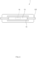
- FIG. 3 is a left view of FIG. 1 .
- a secondary battery 1 As illustrated in FIGS. 1 to 3 , a secondary battery 1 according to the first embodiment of the present invention has a structure including a temperature sensor 15 that measures a temperature inside a pouch 12.
- the secondary battery 1 includes an electrode assembly 11, a pouch 12 accommodating the electrode assembly 11, an electrode lead 13 coupled to the electrode assembly 11, a lead film 14 provided on the electrode lead 13, and a temperature sensor 15 that measures a temperature inside the pouch 12.
- the electrode assembly 11 has a structure in which separators and electrodes are alternately stacked, and each of the electrodes includes an electrode tab 111.
- the electrode comprises a positive electrode and a negative electrode
- the electrode tab 111 includes a positive electrode tab provided on the positive electrode and a negative electrode tab provided on the negative electrode.
- the pouch 12 includes an accommodation part 121 that accommodates the electrode assembly 11, and a sealing part 122 disposed along an edge surface of the accommodation part 121 to seal the accommodation part 121.
- the electrode lead 13 has a long rectangular plate shape and has a structure in which a rear end (end facing the electrode assembly in FIG. 2 ) is coupled to the electrode tab 111, and a front end is withdrawn out of the pouch 12.
- FIG. 4 is a perspective view illustrating the temperature sensor and the electrode lead of the secondary battery according to the first embodiment of the present invention.
- the electrode lead 13 is provided with an insertion hole 131 extending from the inside to the outside of the pouch 12, and referring to FIG. 4 , the insertion hole 131 passes in a vertical direction (vertical direction when viewed in FIG. 4 ). That is, the insertion hole 131 is provided to be elongated in a full-length direction of the electrode lead 13.
- the temperature sensor 15 is inserted into the insertion hole 131.
- the lead film 14 is configured to increase in sealing force between the sealing part 122 of the pouch 12 and the electrode lead 13. That is, the lead film 14 is provided in a shape that surrounds a circumferential surface of the electrode lead 13 disposed on the sealing part 122 of the pouch 12.
- FIG. 5 is a plan view illustrating the temperature sensor 15 illustrated in FIG. 4
- FIG. 6 is a cross-sectional view taken along line A-A of FIG. 4 .
- the temperature sensor 15 has a structure to be inserted into the insertion hole 131, as illustrated in FIGS. 5 and 6 .
- the temperature sensor 15 includes a temperature measurement part 151 having a thermistor chip 1511 disposed inside the pouch 12 to measure the temperature inside the pouch 12 and a connector 152 having a terminal 1521 disposed outside the pouch 12.
- the connector 152 includes the terminal 1521 connected to a temperature measurement device (not shown), and the temperature measurement device compares an internal temperature of the pouch 12 received from the connector 152 to a set temperature in real time. Particularly, the temperature measurement device displays the internal temperature of the pouch 12 received from the connector 152 on an external display window in real time.
- the temperature sensor 15 measures the internal temperature of the pouch 12 through the thermistor chip 1511 of the temperature measurement part 151, and the connector 152 transmits the measured temperature that is measured by the thermistor chip 1511 to the temperature measurement device to inspect and display the internal temperature of the pouch 12.
- the temperature sensor 15 may be inserted into the insertion hole 131 defined in the electrode lead 13 to increase in fixing force of the temperature sensor 15 and also accurately measure the internal temperature of the pouch 12 and quickly transmit the measured internal temperature to the outside. Particularly, the temperature sensor 15 may prevent the sealing force between the sealing part 122 of the pouch 12 and the lead film 14 from being deteriorated by minimizing the increase in thickness of the electrode lead 13.
- the temperature sensor 15 may be provided at a thickness smaller than or equal to that of the electrode lead 13 in which the insertion hole 131 is defined. Preferably, the temperature sensor 15 may be provided at the same thickness as the electrode lead 13. Thus, an occurrence of a height difference between the temperature sensor 15 and the electrode lead 13 may be minimized, and as a result, adhesion and attachment between the temperature sensor 15 and the lead film 14 may increase.
- an anti-oxidation protection layer 154 may be applied on a surface of the temperature measurement part 151 to prevent the temperature measurement part 151 from being oxidized by the electrolyte.
- the anti-oxidation protection layer 154 may be provided as a polymer coating layer.
- the protection layer 154 for preventing the oxidation may be made of a Parylene material.
- the Parylene coating refers to polymer coating that is deposited on an object in the form of a gas in a vacuum state in a micro-thickness unit, regardless of a shape thereof.
- the Parylene coating may be used on portions that require LED surface protection, PCB surface protection, corrosion resistance, chemical resistance, chemical resistance, lubricity, etc.
- the temperature sensor 15 is provided between the temperature measurement part 151 and the connector 152 and is provided with a connection part 153 that is in contact with the lead film 14.
- the connection part 153 may be provided with a reinforcement layer 155 to increase in adhesion with the lead film 14.
- the reinforcement layer 155 may be made of a metal material plated on a surface of the connection part 153, and the metal material may be gold or nickel (Ni). Thus, the reinforcement layer 155 may be plated on the surface of the connection part 153 to increase in adhesion and sealing force between the connection part 153 and the lead film 14.
- FIG. 7 is a plan view illustrating a state in which the temperature sensor and the electrode lead are coupled to each other in the present invention.
- a sealing material 156 provided between the temperature sensor 15 and the inner wall of the insertion hole 131 to seal a gap between the temperature sensor 15 and the inner wall of the insertion hole 131 may be further provided. That is, as illustrated in FIG. 7 , the sealing material 156 serves to close the gap between the temperature sensor 15 and the insertion hole 131. Thus, a gap between the insertion hole 131 and the temperature sensor 15 may be stably sealed.
- the sealing material 156 may be made of the same material as the lead film 14.
- the sealing material 156 may be polypropylene.
- the temperature sensor 15 having the above-described structure may be stably fixed to the secondary battery by being inserted into the insertion hole 131 defined in the electrode lead 13 and may accurately measure the temperature inside the pouch 12.
- the secondary battery 1 may accurately measure the temperature inside the pouch 12 by including the temperature sensor 15 that measures the temperature inside the pouch 12.
- FIG. 8 is a flowchart illustrating a method for manufacturing the secondary battery according to the first embodiment of the present invention.
- a method for manufacturing a secondary battery according to the first embodiment of the present invention includes a process (a) of preparing a temperature sensor 15, a process (b) of processing an electrode lead 13, a process (c) of inserting the temperature sensor 15 into the electrode lead 13, a process (d) of disposing the electrode assembly 11, into which the temperature sensor 15 is inserted, in a pouch 12, a process (e) of disposing a lead film 14, and a process (f) of sealing the pouch 12.
- the temperature sensor 15 is prepared.
- the temperature sensor 15 includes a temperature measurement part 151 having a thermistor chip 1511 that measures a temperature, a connector 152 through which the temperature of the temperature measurement part 151 is transmitted, and a connection part 153 that connects the temperature measurement part 151 to the connector 152.
- the process (a) may further include a process of applying an anti-oxidation protection layer 154 on a surface of the temperature measurement part 151 to prevent the temperature measurement part 151 from being oxidized by an electrolyte. That is, the anti-oxidation protection layer 154 is formed by depositing Parylene coating on the temperature measurement part 151.
- the process (a) may further include a process of forming a reinforcement layer 155 on a surface of the connection part 153 to increase in adhesion between the connection part 153 and the lead film 14. That is, the reinforcement layer 155 is made of a metal material and is formed by being plated on the surface of the connection part 153.
- the metal material may be nickel (Ni) or gold.
- an insertion hole 131 is processed by cutting or punching a surface of one side of the pouch 12.
- the insertion hole 131 has a length so that one end there of is disposed inside the pouch 12, and the other end thereof is disposed outside the pouch 12.
- the insertion hole 131 may have a width corresponding to the length in a full-width direction of the temperature sensor 15 to minimize a gap between the insertion hole 131 and the temperature sensor 15 and prevent the temperature sensor 15 from moving within the insertion hole 131.
- the temperature sensor 15 may be provided at a thickness smaller than or equal to that of the electrode lead 13 in which the insertion hole 131 is defined.
- the temperature sensor 15 may be provided at the same thickness as the electrode lead 13.
- a rear end of the electrode lead 13 is coupled to an electrode tab 111 provided on the electrode assembly 11, and the temperature sensor 15 is installed in the insertion hole 131 of the electrode lead 13.
- the temperature measurement part 151 of the temperature sensor 15 is disposed inside the pouch 12, and the connector 152 of the temperature sensor 15 is inserted to be disposed outside the housing 12.
- the process (c) further includes a process of inserting a sealing material 156 into the gap between the inner wall of the insertion hole 131 and the temperature sensor to seal the gap after the temperature sensor 15 is inserted into the insertion hole 131 of the electrode lead 13.
- the gap between the insertion hole 131 and the temperature sensor 15 may be stably sealed.
- the sealing material 156 may be made of the same material as the lead film 14.
- the adhesion between the sealing material 156 and the lead film 14 may increase.
- the electrode assembly 11 is accommodated in the pouch 12, the temperature measurement part 151 of the temperature sensor 15 is disposed inside the pouch 12, and the connector 152 of the temperature sensor 15 is disposed outside the pouch 12.
- the lead film 14 surrounding the electrode lead 13 is coupled to pass between the temperature measurement part 151 and the connector 152.
- a portion of the sealing part 122 of the pouch 12 is sealed, and then, an electrolyte is injected into a non-sealed portion of the pouch 12 to impregnate the electrode assembly 11, thereby sealing the non-sealed portion of the pouch 12.
- a finished secondary battery 1 may be manufactured.
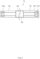
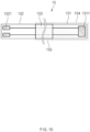
- FIG. 9 is a perspective view of a temperature sensor according to a second embodiment of the present invention
- FIG. 10 is a plan view of FIG. 9 .
- a temperature sensor 15 according to the second embodiment of the present invention is manufactured by separately commercializing only the temperature sensor 15 from the secondary battery 1 according to the first embodiment described above.
- the temperature sensor 15 includes a thermistor chip 1511 provided at one end thereof to measure a temperature, a connector 152 provided at the other end thereof, and a connection part 153 connecting the temperature measurement part 151 to the connector 152.
- connection part 153 may be provided with a reinforcement layer 155 to increase in adhesion, and the reinforcement layer 155 may be made of a metal material that is plated on the connection part 153. Since the reinforcement layer 155 has been described in detail in the first embodiment, detailed description thereof will be omitted.
- the temperature measurement part 151 may be coated with an anti-oxidation protection layer 154. Since the anti-oxidation protection layer 154 has been described in detail in the first embodiment, detailed description thereof will be omitted.
- the temperature sensor 15 according to the second embodiment of the present invention may improve marketability by commercializing only the temperature sensor 15 separately from the secondary battery 1 according to the first embodiment.
Landscapes
- Chemical & Material Sciences (AREA)
- Chemical Kinetics & Catalysis (AREA)
- Electrochemistry (AREA)
- General Chemical & Material Sciences (AREA)
- Physics & Mathematics (AREA)
- Engineering & Computer Science (AREA)
- Manufacturing & Machinery (AREA)
- General Physics & Mathematics (AREA)
- Nonlinear Science (AREA)
- Secondary Cells (AREA)
- Measuring Temperature Or Quantity Of Heat (AREA)
Abstract
Description
- The present application claims the benefit of the priority of
Korean Patent Application No. 10-2022-0088571, filed on July 18, 2022 - The present invention relates to a temperature sensor, a secondary battery including the same, and a method for manufacturing the secondary battery. Particularly, the present invention relates to a temperature sensor capable of measuring a temperature inside a pouch, a secondary battery including the same, and a method for manufacturing the secondary battery.
- In general, secondary batteries refer to chargeable and dischargeable batteries, unlike primary batteries that is impossible to charge. Such secondary batteries are widely used in high-tech electronic devices such as phones, notebook computers, and camcorders.
- The secondary batteries are classified into a can-type secondary battery, in which an electrode assembly is embedded in a metal can, and a pouch-type secondary battery in which an electrode assembly is embedded in a pouch. A can-type secondary battery includes an electrode assembly, a can accommodating the electrode assembly, and a cap assembly mounted in an opening of the can. The pouch-type secondary battery includes an electrode assembly and a pouch accommodating the electrode assembly. The electrode assembly is divided into a jelly-roll type (wound type) electrode assembly, a stack type electrode assembly, and a stack/folding type electrode assembly.
- The pouch-type secondary battery use a method for measuring a temperature at the outside of the pouch when measuring the temperature.
- However, in pouch-type secondary battery, there is a temperature difference between the inside and outside of the pouch, and thus, there is a limitation that it is difficult to accurately measure the temperature without measuring an internal temperature of the pouch.
- An object of the present invention is to provide a temperature sensor capable of accurately measuring a temperature inside a pouch, a secondary battery including the same, and a method for manufacturing the secondary battery.
- A secondary battery of the present invention may include: an electrode assembly; a pouch configured to accommodate the electrode assembly; an electrode lead which is coupled to an electrode tab provided on the electrode assembly, of which a front end is withdrawn out of the pouch, and in which an insertion hole extending from the inside to the outside of the pouch is defined; and a temperature sensor inserted into the insertion hole, wherein the temperature sensor comprises a temperature measurement part disposed inside the pouch to measure a temperature inside the pouch and a connector disposed outside the pouch.
- The temperature sensor may be provided at a thickness smaller than or equal to that of the electrode lead in which the insertion hole is defined.
- The temperature measurement part may be coated with an anti-oxidation protection layer.
- The anti-oxidation protection layer may be provided as a polymer coating layer, and the polymer coating layer may be made of a Parylene material.
- A lead film may be provided on the electrode lead disposed on a sealing part of the pouch, the temperature sensor may be provided with a connection part that is disposed between the temperature measurement part and the connector and is in contact with the lead film, and the connection part may be provided with a reinforcement layer that increases in adhesion to the lead film.
- The reinforcement layer may be made of a metal material that is plated on the connection part.
- The secondary battery may further include a sealing material provided between the temperature sensor and an inner wall of the insertion hole to seal a gap between the temperature sensor and the inner wall of the insertion hole.
- The sealing material may be made of the same material as the lead film.
- A method for manufacturing a secondary battery of the present invention may include: a process (a) of preparing a temperature sensor; a process (b) of cutting a surface of one side of the electrode lead to process an insertion hole; a process (c) of coupling a rear end of the electrode lead to an electrode tab of an electrode assembly and inserting the temperature sensor into an insertion hole of the electrode lead; a process (d) of accommodating the electrode assembly into a pouch, wherein a temperature measurement part of the temperature sensor may be disposed inside the pouch, and a connector of the temperature sensor may be disposed outside the pouch.
- In the process (b), the temperature sensor may be provided at a thickness smaller than or equal to that of the electrode lead in which the insertion hole is defined.
- The process (a) may further include a process of applying an anti-oxidization protection layer on a surface of the temperature measurement part, wherein the anti-oxidization protection layer may be formed by depositing Parylene coating on the temperature measurement part.
- The process (a) may further include a process of forming a reinforcement layer for increasing in adhesion to a connection part provided between the temperature measurement and the connector, wherein the reinforcement layer may be made of a metal material and formed by being plated on a surface of the connection part.
- The process (c) may further include a process of inserting a sealing material into a gap between an inner wall of an insertion hole and the temperature sensor to seal the gap after the temperature sensor is inserted into the insertion hole of the electrode lead.
- The method may further include, after the process (d),: a process (e) disposing a lead film surrounding the electrode lead to pass between the temperature measurement part and the connector; and a process of sealing a portion of the sealing part of the pouch, injecting an electrolyte into a non-sealed portion of the pouch to impregnate the electrode assembly, and sealing the non-sealed portion of the pouch to manufacture a secondary battery.
- A temperature sensor of the present invention includes: a temperature measurement part having a thermistor provided on one end thereof to measure a temperature; a connector provided on the other end thereof; and a connection part configured to connect the temperature measurement part to the connector, wherein the connection part may be provided with a reinforcement layer that increases in adhesion.
- The secondary battery of the present invention may include the temperature sensor that measures the internal temperature of the pouch, and the temperature sensor may be provided to be inserted into the insertion hole defined in the electrode lead. Due to these features, the increase in thickness of the sealing part of the pouch in which the electrode lead is disposed may be minimized, and in particular, the temperature sensor may be more stably fixed.
- In addition, in the secondary battery of the present invention, the temperature sensor may be provided at the temperature less than or equal to that of the electrode lead in which the insertion hole is defined. Due to this feature, the sealing part of the pouch may be prevented from increasing in thickness.
- In addition, in the secondary battery of the present invention, the anti-oxidation protection layer may be applied on the temperature measurement part of the temperature sensor, and the anti-oxidation protection layer may be made of a Parylene material. Due to this feature, the temperature measurement part may be greatly prevented from being oxidized by the electrolyte.
- In addition, in the temperature sensor in the secondary battery of the present invention, the connection part may be provided between the temperature measurement part and the connector, and the connection part may be plated with the reinforcement layer made of the metal material to improve the adhesion to the lead film. Due to these features, the sealing force between the temperature sensor and the lead film may increase.
- In addition, in the secondary battery of the present invention, the sealing material may be provided between the temperature sensor and the inner wall of the insertion hole of the electrode lead. Due to this feature, the portion between the temperature sensor and the inner wall of the insertion hole may be stably sealed.
-
-
FIG. 1 is a perspective view of a secondary battery according to a first embodiment of the present invention. -
FIG. 2 is a plan view ofFIG. 1 . -
FIG. 3 is a left view ofFIG. 1 . -
FIG. 4 is a perspective view illustrating a temperature sensor and an electrode lead of the secondary battery according to the first embodiment of the present invention. -
FIG. 5 is a plan view illustrating the temperature sensor illustrated inFIG. 4 . -
FIG. 6 is a cross-sectional view taken along line A-A ofFIG. 4 . -
FIG. 7 is a plan view illustrating a state in which the temperature sensor and the electrode lead are coupled to each other in the present invention. -
FIG. 8 is a flowchart illustrating a method for manufacturing the secondary battery according to the first embodiment of the present invention. -
FIG. 9 is a perspective view of a temperature sensor according to a second embodiment of the present invention. -
FIG. 10 is a plan view ofFIG. 9 . - Hereinafter, embodiments of the present invention will be described in detail with reference to the accompanying drawings in such a manner that the technical idea of the present invention may easily be carried out by a person with ordinary skill in the art to which the invention pertains. The present invention may, however, be embodied in different forms and should not be construed as limited to the embodiments set forth herein. In the drawings, anything unnecessary for describing the present invention will be omitted for clarity, and also like reference numerals in the drawings denote like elements.
-
FIG. 1 is a perspective view of a secondary battery according to a first embodiment of the present invention,FIG. 2 is a plan view ofFIG. 1 , andFIG. 3 is a left view ofFIG. 1 . - As illustrated in
FIGS. 1 to 3 , asecondary battery 1 according to the first embodiment of the present invention has a structure including atemperature sensor 15 that measures a temperature inside apouch 12. - That is, the
secondary battery 1 according to the first embodiment of the present invention includes anelectrode assembly 11, apouch 12 accommodating theelectrode assembly 11, anelectrode lead 13 coupled to theelectrode assembly 11, alead film 14 provided on theelectrode lead 13, and atemperature sensor 15 that measures a temperature inside thepouch 12. - The
electrode assembly 11 has a structure in which separators and electrodes are alternately stacked, and each of the electrodes includes anelectrode tab 111. - The electrode comprises a positive electrode and a negative electrode, and the
electrode tab 111 includes a positive electrode tab provided on the positive electrode and a negative electrode tab provided on the negative electrode. - The
pouch 12 includes anaccommodation part 121 that accommodates theelectrode assembly 11, and a sealingpart 122 disposed along an edge surface of theaccommodation part 121 to seal theaccommodation part 121. - The
electrode lead 13 has a long rectangular plate shape and has a structure in which a rear end (end facing the electrode assembly inFIG. 2 ) is coupled to theelectrode tab 111, and a front end is withdrawn out of thepouch 12. -
FIG. 4 is a perspective view illustrating the temperature sensor and the electrode lead of the secondary battery according to the first embodiment of the present invention. - Particularly, referring to
FIG. 4 , theelectrode lead 13 is provided with aninsertion hole 131 extending from the inside to the outside of thepouch 12, and referring toFIG. 4 , theinsertion hole 131 passes in a vertical direction (vertical direction when viewed inFIG. 4 ). That is, theinsertion hole 131 is provided to be elongated in a full-length direction of theelectrode lead 13. - The
temperature sensor 15 is inserted into theinsertion hole 131. - The
lead film 14 is configured to increase in sealing force between the sealingpart 122 of thepouch 12 and theelectrode lead 13. That is, thelead film 14 is provided in a shape that surrounds a circumferential surface of theelectrode lead 13 disposed on the sealingpart 122 of thepouch 12. -
FIG. 5 is a plan view illustrating thetemperature sensor 15 illustrated inFIG. 4 , andFIG. 6 is a cross-sectional view taken along line A-A ofFIG. 4 . - The
temperature sensor 15 has a structure to be inserted into theinsertion hole 131, as illustrated inFIGS. 5 and6 . - Particularly, the
temperature sensor 15 includes atemperature measurement part 151 having athermistor chip 1511 disposed inside thepouch 12 to measure the temperature inside thepouch 12 and aconnector 152 having a terminal 1521 disposed outside thepouch 12. - Here, the
connector 152 includes the terminal 1521 connected to a temperature measurement device (not shown), and the temperature measurement device compares an internal temperature of thepouch 12 received from theconnector 152 to a set temperature in real time. Particularly, the temperature measurement device displays the internal temperature of thepouch 12 received from theconnector 152 on an external display window in real time. - That is, the
temperature sensor 15 measures the internal temperature of thepouch 12 through thethermistor chip 1511 of thetemperature measurement part 151, and theconnector 152 transmits the measured temperature that is measured by thethermistor chip 1511 to the temperature measurement device to inspect and display the internal temperature of thepouch 12. - As described above, the
temperature sensor 15 may be inserted into theinsertion hole 131 defined in theelectrode lead 13 to increase in fixing force of thetemperature sensor 15 and also accurately measure the internal temperature of thepouch 12 and quickly transmit the measured internal temperature to the outside. Particularly, thetemperature sensor 15 may prevent the sealing force between the sealingpart 122 of thepouch 12 and thelead film 14 from being deteriorated by minimizing the increase in thickness of theelectrode lead 13. - The
temperature sensor 15 may be provided at a thickness smaller than or equal to that of theelectrode lead 13 in which theinsertion hole 131 is defined. Preferably, thetemperature sensor 15 may be provided at the same thickness as theelectrode lead 13. Thus, an occurrence of a height difference between thetemperature sensor 15 and theelectrode lead 13 may be minimized, and as a result, adhesion and attachment between thetemperature sensor 15 and thelead film 14 may increase. - Since the
temperature measurement part 151 is disposed inside thepouch 12, oxidation may occur due to the electrolyte. To prevent the oxidation, ananti-oxidation protection layer 154 may be applied on a surface of thetemperature measurement part 151 to prevent thetemperature measurement part 151 from being oxidized by the electrolyte. - Here, the
anti-oxidation protection layer 154 may be provided as a polymer coating layer. In more detail, theprotection layer 154 for preventing the oxidation may be made of a Parylene material. - Here, the Parylene coating refers to polymer coating that is deposited on an object in the form of a gas in a vacuum state in a micro-thickness unit, regardless of a shape thereof. The Parylene coating may be used on portions that require LED surface protection, PCB surface protection, corrosion resistance, chemical resistance, chemical resistance, lubricity, etc.
- The
temperature sensor 15 is provided between thetemperature measurement part 151 and theconnector 152 and is provided with aconnection part 153 that is in contact with thelead film 14. Here, theconnection part 153 may be provided with areinforcement layer 155 to increase in adhesion with thelead film 14. - The
reinforcement layer 155 may be made of a metal material plated on a surface of theconnection part 153, and the metal material may be gold or nickel (Ni). Thus, thereinforcement layer 155 may be plated on the surface of theconnection part 153 to increase in adhesion and sealing force between theconnection part 153 and thelead film 14. -
FIG. 7 is a plan view illustrating a state in which the temperature sensor and the electrode lead are coupled to each other in the present invention. - A sealing
material 156 provided between thetemperature sensor 15 and the inner wall of theinsertion hole 131 to seal a gap between thetemperature sensor 15 and the inner wall of theinsertion hole 131 may be further provided. That is, as illustrated inFIG. 7 , the sealingmaterial 156 serves to close the gap between thetemperature sensor 15 and theinsertion hole 131. Thus, a gap between theinsertion hole 131 and thetemperature sensor 15 may be stably sealed. - The sealing
material 156 may be made of the same material as thelead film 14. Preferably, the sealingmaterial 156 may be polypropylene. - The
temperature sensor 15 having the above-described structure may be stably fixed to the secondary battery by being inserted into theinsertion hole 131 defined in theelectrode lead 13 and may accurately measure the temperature inside thepouch 12. - Therefore, the
secondary battery 1 according to the first embodiment of the present invention may accurately measure the temperature inside thepouch 12 by including thetemperature sensor 15 that measures the temperature inside thepouch 12. - Hereinafter, a method for manufacturing the
secondary battery 1 according to the first embodiment of the present invention will be described. -
FIG. 8 is a flowchart illustrating a method for manufacturing the secondary battery according to the first embodiment of the present invention. - As illustrated in
FIG. 8 , a method for manufacturing a secondary battery according to the first embodiment of the present invention includes a process (a) of preparing atemperature sensor 15, a process (b) of processing anelectrode lead 13, a process (c) of inserting thetemperature sensor 15 into theelectrode lead 13, a process (d) of disposing theelectrode assembly 11, into which thetemperature sensor 15 is inserted, in apouch 12, a process (e) of disposing alead film 14, and a process (f) of sealing thepouch 12. - In the process (a), the
temperature sensor 15 is prepared. Thetemperature sensor 15 includes atemperature measurement part 151 having athermistor chip 1511 that measures a temperature, aconnector 152 through which the temperature of thetemperature measurement part 151 is transmitted, and aconnection part 153 that connects thetemperature measurement part 151 to theconnector 152. - The process (a) may further include a process of applying an
anti-oxidation protection layer 154 on a surface of thetemperature measurement part 151 to prevent thetemperature measurement part 151 from being oxidized by an electrolyte. That is, theanti-oxidation protection layer 154 is formed by depositing Parylene coating on thetemperature measurement part 151. - The process (a) may further include a process of forming a
reinforcement layer 155 on a surface of theconnection part 153 to increase in adhesion between theconnection part 153 and thelead film 14. That is, thereinforcement layer 155 is made of a metal material and is formed by being plated on the surface of theconnection part 153. - The metal material may be nickel (Ni) or gold.
- In the process (b), an
insertion hole 131 is processed by cutting or punching a surface of one side of thepouch 12. Here, theinsertion hole 131 has a length so that one end there of is disposed inside thepouch 12, and the other end thereof is disposed outside thepouch 12. In addition, theinsertion hole 131 may have a width corresponding to the length in a full-width direction of thetemperature sensor 15 to minimize a gap between theinsertion hole 131 and thetemperature sensor 15 and prevent thetemperature sensor 15 from moving within theinsertion hole 131. - In addition, in the process (b), the
temperature sensor 15 may be provided at a thickness smaller than or equal to that of theelectrode lead 13 in which theinsertion hole 131 is defined. Preferably, thetemperature sensor 15 may be provided at the same thickness as theelectrode lead 13. Thus, the occurrence of the height difference between thetemperature sensor 15 and theelectrode lead 13 may be prevented, and as a result, the adhesion and sealing force between thetemperature sensor 15 and thelead film 14 may increase. - In the process (c), a rear end of the
electrode lead 13 is coupled to anelectrode tab 111 provided on theelectrode assembly 11, and thetemperature sensor 15 is installed in theinsertion hole 131 of theelectrode lead 13. Here, thetemperature measurement part 151 of thetemperature sensor 15 is disposed inside thepouch 12, and theconnector 152 of thetemperature sensor 15 is inserted to be disposed outside thehousing 12. - The process (c) further includes a process of inserting a sealing
material 156 into the gap between the inner wall of theinsertion hole 131 and the temperature sensor to seal the gap after thetemperature sensor 15 is inserted into theinsertion hole 131 of theelectrode lead 13. Thus, the gap between theinsertion hole 131 and thetemperature sensor 15 may be stably sealed. Here, the sealingmaterial 156 may be made of the same material as thelead film 14. Thus, the adhesion between the sealingmaterial 156 and thelead film 14 may increase. - In the process (d), the
electrode assembly 11 is accommodated in thepouch 12, thetemperature measurement part 151 of thetemperature sensor 15 is disposed inside thepouch 12, and theconnector 152 of thetemperature sensor 15 is disposed outside thepouch 12. - In the process (e), the
lead film 14 surrounding theelectrode lead 13 is coupled to pass between thetemperature measurement part 151 and theconnector 152. - In the process (f), a portion of the sealing
part 122 of thepouch 12 is sealed, and then, an electrolyte is injected into a non-sealed portion of thepouch 12 to impregnate theelectrode assembly 11, thereby sealing the non-sealed portion of thepouch 12. - When the above processes are completed, a finished
secondary battery 1 may be manufactured. - Hereinafter, in descriptions of another embodiment of the present invention, constituents having the same function as the above-mentioned embodiment have been given the same reference numeral in the drawings, and thus duplicated description will be omitted.
-
FIG. 9 is a perspective view of a temperature sensor according to a second embodiment of the present invention, andFIG. 10 is a plan view ofFIG. 9 . - A
temperature sensor 15 according to the second embodiment of the present invention is manufactured by separately commercializing only thetemperature sensor 15 from thesecondary battery 1 according to the first embodiment described above. - That is, as illustrated in
FIGS. 9 and10 , thetemperature sensor 15 according to the second embodiment of the present invention includes athermistor chip 1511 provided at one end thereof to measure a temperature, aconnector 152 provided at the other end thereof, and aconnection part 153 connecting thetemperature measurement part 151 to theconnector 152. - Here, the
connection part 153 may be provided with areinforcement layer 155 to increase in adhesion, and thereinforcement layer 155 may be made of a metal material that is plated on theconnection part 153. Since thereinforcement layer 155 has been described in detail in the first embodiment, detailed description thereof will be omitted. - The
temperature measurement part 151 may be coated with ananti-oxidation protection layer 154. Since theanti-oxidation protection layer 154 has been described in detail in the first embodiment, detailed description thereof will be omitted. - Therefore, the
temperature sensor 15 according to the second embodiment of the present invention may improve marketability by commercializing only thetemperature sensor 15 separately from thesecondary battery 1 according to the first embodiment. - Accordingly, the scope of the present invention is defined by the appended claims more than the foregoing description and the exemplary embodiments described therein. Various modifications made within the meaning of an equivalent of the claims of the invention and within the claims are to be regarded to be in the scope of the present invention.
-
- 1: Secondary battery
- 11: Electrode assembly
- 111: Electrode tab
- 12: Pouch
- 121: Accommodation part
- 122: Sealing part
- 13: Electrode lead
- 131: Insertion hole
- 14: Lead film
- 15: Temperature sensor
- 151: Temperature measurement part
- 1511: Thermistor chip
- 152: Connector
- 153: Connection part
- 154: Anti-oxidation protection layer
- 155: Reinforcement layer
- 156: Sealing material
Claims (15)
- A secondary battery comprising:an electrode assembly;a pouch configured to accommodate the electrode assembly;an electrode lead which is coupled to an electrode tab provided on the electrode assembly, of which a front end is withdrawn out of the pouch, and in which an insertion hole extending from the inside to the outside of the pouch is defined; anda temperature sensor inserted into the insertion hole, wherein the temperature sensor comprises a temperature measurement part disposed inside the pouch to measure a temperature inside the pouch and a connector disposed outside the pouch.
- The secondary battery of claim 1, wherein the temperature sensor is provided at a thickness smaller than or equal to that of the electrode lead in which the insertion hole is defined.
- The secondary battery of claim 1, wherein the temperature measurement part is coated with an anti-oxidation protection layer.
- The secondary battery of claim 3, wherein the anti-oxidation protection layer is provided as a polymer coating layer, and
the polymer coating layer is made of a Parylene material. - The secondary battery of claim 1, wherein a lead film is provided on the electrode lead disposed on a sealing part of the pouch,the temperature sensor is provided with a connection part that is disposed between the temperature measurement part and the connector and is in contact with the lead film, andthe connection part is provided with a reinforcement layer that increases in adhesion to the lead film.
- The secondary battery of claim 5, wherein the reinforcement layer is made of a metal material that is plated on the connection part.
- The secondary battery of claim 5, further comprising a sealing material provided between the temperature sensor and an inner wall of the insertion hole to seal a gap between the temperature sensor and the inner wall of the insertion hole.
- The secondary battery of claim 7, wherein the sealing material is made of the same material as the lead film.
- A method for manufacturing a secondary battery, the method comprising:a process (a) of preparing a temperature sensor;a process (b) of cutting a surface of one side of the electrode lead to process an insertion hole;a process (c) of coupling a rear end of the electrode lead to an electrode tab of an electrode assembly and inserting the temperature sensor into an insertion hole of the electrode lead;a process (d) of accommodating the electrode assembly into a pouch, wherein a temperature measurement part of the temperature sensor is disposed inside the pouch, and a connector of the temperature sensor is disposed outside the pouch.
- The method of claim 9, wherein, in the process (b), the temperature sensor is provided at a thickness smaller than or equal to that of the electrode lead in which the insertion hole is defined.
- The method of claim 9, wherein the process (a) further comprises a process of applying an anti-oxidization protection layer on a surface of the temperature measurement part,
wherein the anti-oxidization protection layer is formed by depositing Parylene coating on the temperature measurement part. - The method of claim 9, wherein the process (a) further comprises a process of forming a reinforcement layer for increasing in adhesion to a connection part provided between the temperature measurement and the connector,
wherein the reinforcement layer is made of a metal material and formed by being plated on a surface of the connection part. - The method of claim 9, wherein the process (c) further comprises a process of inserting a sealing material into a gap between an inner wall of an insertion hole and the temperature sensor to seal the gap after the temperature sensor is inserted into the insertion hole of the electrode lead.
- The method of claim 9, further comprising, after the process (d),:a process (e) disposing a lead film surrounding the electrode lead to pass between the temperature measurement part and the connector; anda process of sealing a portion of the sealing part of the pouch, injecting an electrolyte into a non-sealed portion of the pouch to impregnate the electrode assembly, and sealing the non-sealed portion of the pouch to manufacture a secondary battery.
- A temperature sensor comprising:a temperature measurement part having a thermistor provided on one end thereof to measure a temperature;a connector provided on the other end thereof; anda connection part configured to connect the temperature measurement part to the connector,wherein the connection part is provided with a reinforcement layer that increases in adhesion.
Applications Claiming Priority (2)
| Application Number | Priority Date | Filing Date | Title |
|---|---|---|---|
| KR1020220088571A KR20240011041A (en) | 2022-07-18 | 2022-07-18 | Temperature sensor, secondary battery comprising the same, and method manufacturing of secondary battery |
| PCT/KR2023/009762 WO2024019387A1 (en) | 2022-07-18 | 2023-07-10 | Temperature sensor, secondary battery including same, and method for manufacturing secondary battery |
Publications (2)
| Publication Number | Publication Date |
|---|---|
| EP4507065A1 true EP4507065A1 (en) | 2025-02-12 |
| EP4507065A4 EP4507065A4 (en) | 2025-12-24 |
Family
ID=89618237
Family Applications (1)
| Application Number | Title | Priority Date | Filing Date |
|---|---|---|---|
| EP23843238.9A Pending EP4507065A4 (en) | 2022-07-18 | 2023-07-10 | TEMPERATURE SENSOR, SECONDARY BATTERY, AND METHOD FOR MAKING A SECONDARY BATTERY |
Country Status (6)
| Country | Link |
|---|---|
| US (1) | US20250341429A1 (en) |
| EP (1) | EP4507065A4 (en) |
| JP (1) | JP2025520762A (en) |
| KR (1) | KR20240011041A (en) |
| CN (1) | CN119256423A (en) |
| WO (1) | WO2024019387A1 (en) |
Family Cites Families (13)
| Publication number | Priority date | Publication date | Assignee | Title |
|---|---|---|---|---|
| JP4082071B2 (en) * | 2002-04-12 | 2008-04-30 | 株式会社ジーエス・ユアサコーポレーション | Nonaqueous electrolyte secondary battery |
| JP4569886B2 (en) * | 2003-12-25 | 2010-10-27 | 株式会社大泉製作所 | Manufacturing method of temperature sensor |
| JP2007335352A (en) * | 2006-06-19 | 2007-12-27 | Sony Corp | Nonaqueous electrolyte secondary battery and battery control system |
| JP5249143B2 (en) * | 2009-06-25 | 2013-07-31 | 三菱電線工業株式会社 | Sensor with terminal |
| KR101249347B1 (en) * | 2010-11-04 | 2013-04-01 | 주식회사 엘지화학 | Secondary battery having temperature measuring pad and Protection apparatus for the same |
| KR20130034282A (en) | 2011-09-28 | 2013-04-05 | 에스케이이노베이션 주식회사 | Battery cell having temperature sensor |
| DE102012207999A1 (en) * | 2012-05-14 | 2013-11-14 | Robert Bosch Gmbh | Sheath foil for a galvanic cell, electrochemical storage, electrochemical storage system, flexible foil for a sheath of a galvanic cell and method for determining a state quantity of an electrochemical storage |
| KR101577387B1 (en) * | 2013-05-06 | 2015-12-16 | 주식회사 엘지화학 | Secondary battery, and secondary battery module and secondary battery pack comprising the same |
| CN204558611U (en) * | 2015-03-17 | 2015-08-12 | 北汽福田汽车股份有限公司 | A kind of cell apparatus for internal temperature of battery test |
| JP6612720B2 (en) * | 2016-11-28 | 2019-11-27 | 本田技研工業株式会社 | Secondary battery |
| CN210245669U (en) * | 2019-06-20 | 2020-04-03 | 江西瑞隆锂能科技有限公司 | Inside temperature rise measuring device of soft packet of lithium cell |
| KR102779080B1 (en) * | 2019-07-03 | 2025-03-11 | 주식회사 엘지에너지솔루션 | Secondary battery, method of manufacturing the same and battery module including the same |
| CN214957011U (en) * | 2021-05-21 | 2021-11-30 | 重庆市紫建新能源有限公司 | Lithium ion battery with measurable internal temperature |
-
2022
- 2022-07-18 KR KR1020220088571A patent/KR20240011041A/en active Pending
-
2023
- 2023-07-10 WO PCT/KR2023/009762 patent/WO2024019387A1/en not_active Ceased
- 2023-07-10 JP JP2024575790A patent/JP2025520762A/en active Pending
- 2023-07-10 US US18/866,654 patent/US20250341429A1/en active Pending
- 2023-07-10 CN CN202380041800.5A patent/CN119256423A/en active Pending
- 2023-07-10 EP EP23843238.9A patent/EP4507065A4/en active Pending
Also Published As
| Publication number | Publication date |
|---|---|
| EP4507065A4 (en) | 2025-12-24 |
| CN119256423A (en) | 2025-01-03 |
| WO2024019387A1 (en) | 2024-01-25 |
| KR20240011041A (en) | 2024-01-25 |
| JP2025520762A (en) | 2025-07-03 |
| US20250341429A1 (en) | 2025-11-06 |
Similar Documents
| Publication | Publication Date | Title |
|---|---|---|
| KR102230889B1 (en) | Embedded fiber optic cables for battery management | |
| EP2924761B1 (en) | Rectangular secondary battery | |
| US9793569B2 (en) | Electric storage element | |
| CN103180996B (en) | The manufacture method of the battery cover of belt electrode terminal, the battery cover of belt electrode terminal and enclosed-type battery | |
| US10573939B2 (en) | Secondary battery with film shaped sensor | |
| KR102455848B1 (en) | Jig for measuring internal pressure of cylindrical battery cell | |
| EP2738836A1 (en) | Rectangular battery | |
| US9312573B2 (en) | Battery pack | |
| US11450878B2 (en) | Method for manufacturing cylindrical three-electrode cell, and cylindrical three-electrode cell manufactured thereby | |
| US12166182B2 (en) | Battery with separately arranged winding stop tapes | |
| EP3327820A1 (en) | Cap assembly having improved stability, and circular secondary battery comprising same | |
| KR20030045662A (en) | Sealed battery | |
| EP4044323B1 (en) | Secondary battery and manufacturing method of same | |
| EP3979352B1 (en) | Cylindrical battery | |
| US20250341429A1 (en) | Temperature Sensor, Secondary Battery Including the Same, and Method for Manufacturing the Secondary Battery | |
| EP3690976B1 (en) | Battery cell and battery | |
| EP4398391A1 (en) | Rechargeable battery pack | |
| CN217405508U (en) | Three-electrode battery | |
| JP7333299B2 (en) | BATTERY, BATTERY BATTERY, AND BATTERY MANUFACTURING METHOD | |
| KR102948314B1 (en) | Battery cell | |
| CN114649643A (en) | Secondary battery | |
| CN109154488B (en) | Device for measuring thickness change of electrode of secondary battery and secondary battery in which the device is installed | |
| US20260066501A1 (en) | Secondary battery temperature evaluation apparatus and method and secondary battery for temperature evaluation | |
| KR20230095016A (en) | Cap assembly and secondary battery comprising the same | |
| KR102931500B1 (en) | Secondary battery and battery module including the same |
Legal Events
| Date | Code | Title | Description |
|---|---|---|---|
| STAA | Information on the status of an ep patent application or granted ep patent |
Free format text: STATUS: THE INTERNATIONAL PUBLICATION HAS BEEN MADE |
|
| PUAI | Public reference made under article 153(3) epc to a published international application that has entered the european phase |
Free format text: ORIGINAL CODE: 0009012 |
|
| STAA | Information on the status of an ep patent application or granted ep patent |
Free format text: STATUS: REQUEST FOR EXAMINATION WAS MADE |
|
| 17P | Request for examination filed |
Effective date: 20241106 |
|
| AK | Designated contracting states |
Kind code of ref document: A1 Designated state(s): AL AT BE BG CH CY CZ DE DK EE ES FI FR GB GR HR HU IE IS IT LI LT LU LV MC ME MK MT NL NO PL PT RO RS SE SI SK SM TR |
|
| REG | Reference to a national code |
Ref country code: DE Ref legal event code: R079 Free format text: PREVIOUS MAIN CLASS: H01M0010480000 Ipc: G01K0001140000 |
|
| RIC1 | Information provided on ipc code assigned before grant |
Ipc: G01K 1/14 20210101AFI20250901BHEP Ipc: H01M 10/04 20060101ALI20250901BHEP Ipc: H01M 10/42 20060101ALI20250901BHEP Ipc: H01M 10/48 20060101ALI20250901BHEP Ipc: H01M 50/105 20210101ALI20250901BHEP Ipc: H01M 50/178 20210101ALI20250901BHEP Ipc: H01M 50/186 20210101ALI20250901BHEP Ipc: H01M 50/553 20210101ALI20250901BHEP Ipc: H01M 50/562 20210101ALI20250901BHEP Ipc: H01M 50/569 20210101ALI20250901BHEP Ipc: G01K 7/22 20060101ALI20250901BHEP |
|
| DAV | Request for validation of the european patent (deleted) | ||
| DAX | Request for extension of the european patent (deleted) | ||
| A4 | Supplementary search report drawn up and despatched |
Effective date: 20251126 |
|
| RIC1 | Information provided on ipc code assigned before grant |
Ipc: G01K 1/14 20210101AFI20251120BHEP Ipc: H01M 10/04 20060101ALI20251120BHEP Ipc: H01M 10/42 20060101ALI20251120BHEP Ipc: H01M 10/48 20060101ALI20251120BHEP Ipc: H01M 50/105 20210101ALI20251120BHEP Ipc: H01M 50/178 20210101ALI20251120BHEP Ipc: H01M 50/186 20210101ALI20251120BHEP Ipc: H01M 50/553 20210101ALI20251120BHEP Ipc: H01M 50/562 20210101ALI20251120BHEP Ipc: H01M 50/569 20210101ALI20251120BHEP Ipc: G01K 7/22 20060101ALI20251120BHEP |
|
| GRAP | Despatch of communication of intention to grant a patent |
Free format text: ORIGINAL CODE: EPIDOSNIGR1 |
|
| STAA | Information on the status of an ep patent application or granted ep patent |
Free format text: STATUS: GRANT OF PATENT IS INTENDED |