EP4506974A1 - Actuator for an electrical switching device, electrical switching device and method - Google Patents
Actuator for an electrical switching device, electrical switching device and method Download PDFInfo
- Publication number
- EP4506974A1 EP4506974A1 EP23191099.3A EP23191099A EP4506974A1 EP 4506974 A1 EP4506974 A1 EP 4506974A1 EP 23191099 A EP23191099 A EP 23191099A EP 4506974 A1 EP4506974 A1 EP 4506974A1
- Authority
- EP
- European Patent Office
- Prior art keywords
- actuator
- spring
- actuator structure
- loaded
- coupled
- Prior art date
- Legal status (The legal status is an assumption and is not a legal conclusion. Google has not performed a legal analysis and makes no representation as to the accuracy of the status listed.)
- Pending
Links
Images



Classifications
-
- H—ELECTRICITY
- H01—ELECTRIC ELEMENTS
- H01H—ELECTRIC SWITCHES; RELAYS; SELECTORS; EMERGENCY PROTECTIVE DEVICES
- H01H5/00—Snap-action arrangements, i.e. in which during a single opening operation or a single closing operation energy is first stored and then released to produce or assist the contact movement
- H01H5/04—Energy stored by deformation of elastic members
- H01H5/06—Energy stored by deformation of elastic members by compression or extension of coil springs
-
- H—ELECTRICITY
- H01—ELECTRIC ELEMENTS
- H01H—ELECTRIC SWITCHES; RELAYS; SELECTORS; EMERGENCY PROTECTIVE DEVICES
- H01H3/00—Mechanisms for operating contacts
- H01H3/22—Power arrangements internal to the switch for operating the driving mechanism
- H01H3/30—Power arrangements internal to the switch for operating the driving mechanism using spring motor
-
- H—ELECTRICITY
- H01—ELECTRIC ELEMENTS
- H01H—ELECTRIC SWITCHES; RELAYS; SELECTORS; EMERGENCY PROTECTIVE DEVICES
- H01H3/00—Mechanisms for operating contacts
- H01H3/22—Power arrangements internal to the switch for operating the driving mechanism
- H01H3/30—Power arrangements internal to the switch for operating the driving mechanism using spring motor
- H01H3/3031—Means for locking the spring in a charged state
-
- H—ELECTRICITY
- H01—ELECTRIC ELEMENTS
- H01H—ELECTRIC SWITCHES; RELAYS; SELECTORS; EMERGENCY PROTECTIVE DEVICES
- H01H3/00—Mechanisms for operating contacts
- H01H3/22—Power arrangements internal to the switch for operating the driving mechanism
- H01H3/30—Power arrangements internal to the switch for operating the driving mechanism using spring motor
- H01H3/3005—Charging means
- H01H3/3015—Charging means using cam devices
Definitions
- the invention relates to a spring-loaded actuator for an electrical switching device, the spring-loaded actuator comprising a driver structure for switching the electrical switching device, an actuator structure engaging with the driver structure, and a spring accumulator configured to store energy by means of moving the actuator structure.
- An electrical switching device such as a disconnector or earthing switch, also known a grounding switch, is a protective device included in switchgear components like circuit breakers and isolators.
- earthing switches When circuit breakers are removed and racked out, earthing switches automatically ground a part of a bus bar adjacent to the circuit breakers.
- the earthing switches make contact with the bus bar when the isolator isolates the circuits, discharging any charges that may have gathered there.
- an earthing switch in switchgear is used to ground a remaining charge in a power line after the power line has been removed from its source. A residual charge often remains in a circuit after it has been severed or opened by the circuit breaker and isolator.
- An earthing switch is usually provided to discharge the charge.
- Electrical switching devices often have a snap action closing mechanism for protecting technicians and staff when there is an abnormal current.
- electrical switching devices are designed to withstand short circuits.
- the electrical switching device in a substation has an ability to create short circuits in order to safeguard other electrical devices from damage.
- the electrical switching device is often used with several high-voltage switchgear and also serves as a protective device in an overhaul of high-voltage electrical equipment.
- Such electrical switching device can be actuated by means of the spring-loaded actuator.
- the energy stored in the spring accumulator may be used for the switching operation.
- the spring accumulator may be moved or recharged with energy by a movement of specific parts.
- end switches must be present for delimit traverse of an operating mechanism being moved.
- end positions need to be defined.
- prior art solutions unfortunately do not provide sufficiently secure and easy operation mechanism for moving or recharging such spring-loaded actuators.
- a spring-loaded actuator for an electrical switching device comprising
- the proposed solution thus constitutes an actuator involving a spring load and configured for an electrical switching device.
- the actuator has a first movable part for coupling with and switching the electrical switching device.
- the actuator typically has a second movable part engaging with the first movable part.
- the actuator particularly has an energy storage based on a spring mechanism and coupled to the second movable part. In that way, a movement of the second part at least indirectly may move and switch the electrical switching device.
- a means is provided that merely allows for a one-way movement of the second part from one to another position or the other direction.
- the invention is based on the idea that the actuator structure shall be moved from end to end in order to assure functionality.
- the driver structure may rest in undefined positions when it is not assured that the actuator structure is moved fully from end to end.
- the locking device has been implemented in the actuator in order to make sure that the end positions are achieved when the actuator structure is moved.
- the object is furthermore solved by a system comprising an electrical switching device, the spring-loaded actuator as described herein, and at least one movable contact coupled to the driver structure of the spring-loaded actuator.
- the object is furthermore solved by a method for operating a spring-loaded actuator of an electrical switching device, particularly the spring-loaded actuator or electrical switching device as described herein, comprising
- the driver structure typically relates to a component coupled or to be coupled to the electrical switching device (especially directly coupled) in order to realize a switching based on mechanical energy stored in the spring accumulator.
- the driver structure may be coupled with a pivotable gable to a linearly guided pin of a contact structure.
- the driver structure may comprise a shaft.
- the driver structure may be arranged within the actuator structure, especially coaxially therewith.
- the actuator structure typically relates to a component coupled or to be coupled to the spring accumulator (especially directly coupled) in order to act on the spring accumulator.
- the actuator structure may comprise a lever element that is coupled via a joint to the spring accumulator, especially such that a movement of the actuator structure may realize a change in energy stored in the spring accumulator and/or move the spring accumulator.
- the actuator structure is typically the interface for triggering the actuator to switch the electrical switching device by means of the actuator. This is due to engagement of the actuator structure with the driver structure.
- the engagement section relates to means for engagement with another section. Engagement or engaged typically translate(s) to motion-coupling or motion-coupled.
- the spring accumulator has at least one spring or compressible means to store mechanical energy.
- the spring accumulator can be compressed in a substantially straight or linear direction.
- the spring accumulator is typically held to pivot on one end and to be moved rotationally and/or translationally on another end.
- the spring accumulator stores energy.
- the spring accumulator releases energy.
- the spring accumulator may move the component when decompressing and may store energy when the component is moved.
- the peak in stored energy typically relates to a local maximum amount of energy stored relative to adjacent positions or regions.
- the spring accumulator may assume a maximally compressed arrangement when the peak in stored energy is present.
- the spring accumulator may assume a dead center point with the actuator structure so that the actuator structure can be moved in two opposing directions.
- ⁇ coupled' typically relates to a mechanical connection, preferably indirectly or directly.
- a motion-coupling can be meant.
- a fixed attachment can be meant.
- the locking device typically relates to means that serve to lock a direction of movement and thereby merely allowing a one-way movement after the direction of movement is locked, which movement may be translational and/or rotational in nature.
- the first position typically relates to the position of the spring-loaded actuator, especially the actuator structure, where the spring accumulator is charged or preloaded and/or where the electrical switching device may be disconnected.
- the second position typically relates to the position of the spring-loaded actuator, especially the actuator structure, where the spring accumulator is substantially discharged or un-loaded and/or where the electrical switching device may be connected or earthed.
- high voltage means preferably a voltage ranging from 36 to 1,100 kV.
- a high voltage preferably relates to nominal voltages in the range from above 72 kV to 550 kV, like 145 kV, 245 kV or 420 kV, or even more.
- Nominal currents of the disconnector or earthing switch can be in the range from 1 kA to 5 kA, even high-er such as 80 kA for one second.
- the conductors can be part of a grid for distribution of said high voltage.
- the spring-loaded accumulator and/or the electrical switching device is typically configured for high voltage applications.
- the driver structure and/or the actuator structure is/are mounted movable along and/or about an actuator axis.
- the driver structure and/or the actuator structure may be guided to move along and/or about the actuator axis.
- the driver structure may be guided with a guiding, e.g. a linear or a rotational guiding and/or bearing.
- the actuator structure may be guided with a guiding, e.g. a linear or a rotational guiding and/or bearing.
- the driver structure and/or the actuator structure is/are preferably mounted movable, namely rotatably, especially parallelly, coaxially and/or about the actuator axis.
- the driver structure and/or the actuator structure is/are configured for a rotational movement and/or for a rotation.
- the driver structure and the actuator structure may rotate or pivot about the actuator axis, especially coaxially.
- the engagement section comprises an actuator element, such as a recess and/or protrusion in particular extending in a radial direction.
- the actuator element particularly corresponds to a driver element.
- the driver element may be provided, which driver element may be a recess and/or protrusion in particular extending in the radial direction.
- the driver element is typically comprised by the driver structure.
- the actuator element and the driver element engage with each other for motion-coupling the driver structure and the actuator structure.
- a recess may be configured for a protrusion to stop on circumferential ends of the recess.
- the actuator element and driver element form, preferably along or about a movement axis of the actuator structure, particularly the actuator axis, a clearance.
- the recess in combination with a protrusion may provide a play or clearance or backlash between driver structure and actuator structure.
- the spring accumulator assumes the peak in stored energy when the actuator structure is in a dead center region.
- the actuator structure may be pushed by the spring accumulator in substantially no direction and/or may be pushed by the spring accumulator to stop in the dead center region.
- the driver structure is entrained by and/or mechanically contacts the actuator structure towards the second position in order to switch the electrical switching device.
- the actuator is designed such that a movement of the actuator structure from end to end would be such that in an intermediate position the driver structure is mechanically carried along until the other end. This ensures a reliable and quick switching.
- the dead center region may make up to 5 % or up to 10 % of the movement between the first and second positions.
- the locking device comprising at least one direction locking unit configured to be coupled to the actuator structure and to allow the one-way movement from the first position towards the second position or from the second position towards the first position when coupled to the actuator structure.
- the at least one direction locking unit is movable between an active and an off position and coupled to the actuator structure in the active position and uncoupled in the off position.
- the direction locking unit can be selectively coupled to the actuator structure in order to allow the one-way movement.
- the direction locking unit can be activated and deactivated by a movement into corresponding positions.
- the actuator may be constructed such that the actuator structure can only be moved or rotated when the direction locking unit is in an/the active position.
- a cam disc of the locking device may be provided that may interact with the direction locking unit(s) when being pivoted, for example to move the direction locking unit(s) between positions. This enhances safety.
- the at least one direction locking unit has a ratchet means configured to engage with teeth comprised by the locking device and coupled to the actuator structure.
- the ratchet means may have a lock pawl movable between the off and active positions and/or wherein may be spring-loaded to automatically engage with the teeth.
- the ratchet means may comprise engagement means or the lock pawl for engaging with the teeth of the locking device.
- the engagement means or lock pawl may be pushed by spring load to engage with the teeth.
- the teeth are typically a section of the actuator structure.
- the engagement means or lock pawl may be pivotable between off and active positions.
- the locking device has a control element configured to move the at least one direction locking unit between the off and active position(s), especially against a/the spring-load acting on the ratchet means.
- the control element may be a switch or knob especially for manual operation.
- the control element may be configured for a translational and/or rotational movement.
- each of the at least one direction locking unit overlap so that all off positions can be assumed at a time.
- the direction locking units are both switched off in the case one is switched off.
- the construction can be realized, for example, in that both direction locking units are operated with the same control element.
- each of the at least one direction locking unit are aligned oppositely so that only one active position can be assumed at a time, especially in a normal mode of the locking device.
- the active positions may exclude each other, especially in a/the normal mode of the locking device. For example, when one active position is selected another active position is not possible to be assumed, especially in the normal mode. This can also be realized, for example, in that both direction locking units are operated with the same control element.
- the locking device may assume the normal mode for switching between off and active position(s).
- the locking device may assume a lock mode which is different from the normal mode and/or which is configured to prohibit any movement and/or one-way movement of the actuator structure, especially from the first or the second position towards the other of the first and the second position.
- the lock mode may be that all active positions are assumed concurrently. Switching between lock mode and normal mode may require a translational and/or rotational movement of the locking device, especially starting from the off position(s).
- each of the at least one direction locking units are configured to be assumed simultaneously in a/the lock mode of the locking device, especially wherein the control element can be moved to/into the lock mode, for example starting from a/the normal mode.
- the normal mode may be understood to be present when the lock mode is not present, and/or vice versa.
- the control element may be movable along one direction or path for switching between active and off positions and movable along another direction or path for switching between normal mode, especially off position(s), and lock mode, especially lock position.
- all direction locking units are coupled with the actuator structure to prevent movement in all directions and/or to fix the actuator structure in place.
- the actuator structure is rotatable/pivotable by +/- 6°, +/- 3° or +/- 1,5° when the lock mode is assumed.
- the actuator structure has a first segment coupled to the spring accumulator and a second segment movably coupled to and forming a play with the first segment.
- the first segment and the second segment may be movable along and/or around the actuator axis, especially coaxially, especially rotatably.
- the first and second segments may be provided engaging with each other including a play and/or a backlash.
- the first and second segments may engage via segment elements especially forming the play/backlash.
- the segment elements may be a protrusion and/or a recess.
- the play/backlash may be provided so that the first segment may move at least within the play independently from the second segment, for example to reduce friction and/or realize a freewheel mechanism for the first segment, especially while the second segment may be engaged elsewhere, like a drive unit.
- the first segment is meant to assume the first position, second position and/or dead center region.
- the spring accumulator is coupled directly to the first and/or to the second segment, especially only to the first segment of the segments.
- a drive unit may be provided, which drive unit is coupled to the actuator structure, especially including a play.
- the drive unit is preferably configured to move/rotate/actuate the actuator structure to/towards the dead center region, to the first position and/or to the second position.
- the drive unit may be able to move the actuator structure between the first and second positions especially via the dead center region.
- the drive unit may be an actuator and/or a motor, especially driven by electricity.
- the drive unit may engage directly on the actuator structure, especially on the first and/or on the second segment.
- the drive unit may engage on a lever formed with the actuator structure.
- the lever may be formed directly on the first and/or on the second segment of the actuator structure.
- the drive unit may engage, especially rotationally, with the actuator structure, especially with the first segment and/or with the second segment thereof.
- the drive unit may serve to automatically bring the actuator structure to actuate on the electrical switching device by moving the actuator structure.
- the drive unit may be configured to move the actuator structure from the first position to the dead center region where the driver structure is then also moved; then, the spring accumulator may unload stored energy which results in a further movement of the actuator structure to the second position including a further movement of the driver structure that actuates on the electrical switching device.
- the drive unit may as well be configured to bring back the actuator structure from the second position - especially via the dead center region - to the first position, which of course may include a back-movement of the driver structure.
- the actuator structure has a connector for connecting with a hand crank in order to manually move the actuator structure between the first and the second position.
- the connector may be a free end of a shaft.
- the hand crank may comprise a socket for connection with the connector and/or the free end.
- the connector provides an option for a manual operation and/or setback of the actuator.
- the actuator may be configured such that) in the off position(s) the connector is blocked, for example by means of a movable blocking element comprised by the locking device and/or in order to prohibit a connection with the hand crank.
- the movable locking element may be actuated by and/or motion-coupled with the actuator structure.
- the actuator may be configured such that) in the active position(s) and/or between the first and second position the connector is unblocked in order to enable a/the connection with the hand crank. This enhances safety.
- the locking device has a crank locking means configured for locking the connected hand crank against disconnecting the hand crank especially between the first and the second position.
- the crank locking means may be actuated by and/or motion-coupled with the actuator structure.
- the actuator may be configured such that) in the active position(s) and/or between the first and second position the hand crank is locked in order to secure the hand crank in place.
- the crank locking means may be formed by the blocking element. This enhances safety.
- the blocking element and/or the crank locking means may be actuated by a cam plate or cam disc especially mounted or formed with the actuator structure.
- Said cam plate or cam disc may move together with the movement of the actuator structure.
- Fig. 1 a system with an electrical switching device 1 and a spring-loaded actuator 2 is shown.
- the electrical switching device 1 is coupled to the spring-loaded actuator 2.
- a contact 8 can be moved by means of the actuator 2, especially by means of energy stored in a spring accumulator 70 of the actuator 2.
- the actuator 2 comprises a driver structure 20 mounted movable and coupled to the electrical switching device 1 for switching the electrical switching device 1.
- the actuator 2 furthermore comprises an actuator structure 40 mounted movable between a first A and a second B position.
- the actuator structure 40 has an engagement section 42 engaging with the driver structure 20.
- the spring accumulator 70 is coupled with a joint on one end to a lever element 46 formed at the actuator structure 20 and configured to store energy by means of moving or rotating the actuator structure 20. Another end of the spring accumulator 70 is pivotably or rotatably held. The spring accumulator 70 is arranged in order to have a peak in stored energy between the first position A and the second position B.
- the actuator 2 also has a locking device 80 configured to allow a one-way movement of the actuator structure 20 from the first A or the second B position towards the other of the first A and the second B position.
- the driver structure 20 and the actuator structure 40 are mounted movable, i.e. rotatable, about an actuator axis X. Particularly, a rotational bearing is provided for the structure 20 and/or 40.
- the structures 20 and 40 are mounted rotatably coaxially about the actuator axis X. The driver structure 20 and the actuator structure 40 may thus rotate, especially pivot, about the actuator axis X.
- the engagement section 42 comprises an actuator element 44 formed with a recess extending in a radial direction R especially with respect to the axis X.
- the actuator element 44 particularly corresponds to a driver element 24.
- the driver structure 20 has the driver element 24 which corresponds to the actuator element 44.
- the driver element 24 is formed with a protrusion extending in the radial direction R.
- the driver element 24 and the actuator element 4 engage with each other for motion-coupling the driver structure 20 and the actuator structure 40.
- the actuator element 44 is configured for the driver element 24 to stop on circumferential ends of the actuator element 44.
- the elements 24 and 44 form about the actuator axis X a clearance 3.
- the spring accumulator 70 assumes the peak in stored energy when the actuator structure 40 is in a dead center region C. In the dead center region C, the actuator structure 40 can be pushed by the spring accumulator 70 in substantially no direction and may be pushed to stop in the dead center region C.
- the first position A, the second position B, and the dead center region C are arranged on a curve, particularly a circular curve and/or about the axis X.
- the actuator 2 is designed such that in a movement of the actuator structure 40 from one end position (first position A) to another end (second position B) actuator structure 40 goes along an intermediate position (dead center region C) where the driver structure 20 is mechanically contacted and/or carried along until the other end (second position B).
- the dead center region C makes approx. 5 to 10 % of the angle and/or distance between the first A and second positions B.
- the locking device 80 comprises two direction locking units 81, 82 configured to be selectively coupled to the actuator structure 40.
- a first direction locking unit 81 of the two direction locking units 81, 82 is configured to allow the one-way movement from the first position A towards the second position B when coupled to the actuator structure 40.
- a second direction locking unit 82 of the two direction locking units 81, 82 is configured to allow the one-way movement from the second position B towards the first position A when coupled to the actuator structure 40.
- Each of the two direction locking units 81, 82 is movable between an active and an off position and coupled to the actuator structure 40 in the active position and uncoupled in the off position.
- the actuator 2 is constructed such that the actuator structure 40 can only be moved/rotated when one of the direction locking units 81, 82 is in its active position.
- a cam disc 87 of the locking device 80 is provided that interacts with the direction locking units 81, 82 when being pivoted in order to move the direction locking units 81, 82 between the active and off positions.
- the direction locking units 81, 82 each have a ratchet means 84 configured to engage with teeth 88 of the locking device 80 when in an/the active position.
- Each ratchet means 84 has a lock pawl 86 pivotable between the off and active position.
- the lock pawls 86 are spring-loaded by a spring 96 to automatically engage, particularly re-engage, with the teeth 88.
- the teeth 88 are external teeth or gearings.
- the teeth 88 are a section of the actuator structure 40. Particularly, the lock pawl(s) 86 and/or cam disc 87 may pivot in parallel to the actuator axis X.
- the actuator structure 40 may merely rotate anti-clockwise, wherein during an anti-clockwise rotation of the actuator structure 40 said lock pawl 86 will be repetitively pushed out from the teeth 88 and re-engage with the teeth 88.
- said lock pawl 86 when applying a torque to the actuator structure 40 about the actuator axis X for a desired rotation of the actuator structure 40 in a clockwise direction, said lock pawl 86 will prohibit/block the actuator structure 40 from moving in the clockwise direction.
- the locking device 80 has a control element 90 in the form of a switch or knob configured to move the direction locking units 81, 82 between the off and active positions and partially against the spring-load acting on the ratchet means 86.
- the control element 90 is furthermore guided along a guiding 94 for a substantially linear movement of the control element 90 which facilitates easy manual operation.
- each of the direction locking units 81, 82 fall together so that all off positions can be assumed at a time. Both direction locking units 81, 82 can be operated with the same control element 90.
- each of the direction locking units 81, 82 are aligned oppositely so that only one active position can be assumed at a time.
- the active positions thus exclude each other. For example, as shown in Fig. 1 , when the active position of the first direction locking unit 81 is selected the active position of the second direction locking unit 82 is not possible to be assumed.
- the actuator structure 40 has a first segment 56 coupled to the spring accumulator 70 and a second segment 58 movably coupled to and forming a play 12 with the first segment 56.
- the first segment 56 and the second segment 58 are arranged to coaxially rotate about the actuator axis X.
- the first segment 56 is meant to assume the first position A, second position B and dead center region C.
- the spring accumulator 70 is coupled directly only to the first segment 56 of the two segments 56 and 58.
- the first 56 and second segments 58 engage with each other including the play 12 as a backlash.
- a first segment element 60 of the first segment 56 comprises a protrusion.
- a second segment element 62 of the second segment 58 comprises a recess, e.g. a groove, wherein the segment elements 60 and 62 together constitute the play 12.
- the play 12 is provided so that the first segment 52 can move within the play 12 substantially independently from the second segment 56 to reduce friction when actuating and realize a freewheel mechanism for the first segment 56 while the second segment is engaged with a drive unit 10 and/or the locking device 80.
- the second segment 58 is configured for engagement with the locking device 80 especially as follows.
- the locking units 81 and 82 are optionally coupled in their active positions via the teeth 88 to the second segment 58 for allowing the one-way movement of the actuator structure 40, especially aside from the play 12.
- the drive unit 10 is coupled via a gear especially engaging on the teeth 88 at the second segment 58 of the actuator structure 40.
- the play 12 is included for the drive unit 10 relative to the first segment 56.
- the drive unit 10 is configured to move the actuator structure 40 to the dead center region C, to the second position B, and back to the first position A.
- the drive unit 10 can move the actuator structure 40 between the first A and second B positions via the dead center region C.
- the drive unit 10 has an electrical motor.
- the drive unit 10 engages rotationally with the actuator structure 40, especially with the second segment 58.
- the drive unit 10 can bring the actuator structure 40 to actuate on the electrical switching device 1 by moving the first segment 56 of the actuator structure 40.
- the drive unit 10 can move the actuator structure 40 from the first position A to the dead center region C from where on the driver structure 20 is also being moved until the second position B.
- the spring accumulator 70 will unload stored energy which results in a further movement of the actuator structure 40 to the second position B including a further movement of the driver structure 20 that actuates on the electrical switching device 1 via a gable.
- the gable may guide a pin of the contact 8 in order to close or open an electrical connection by pushing the contact 8 into another contact, especially a tulip contact, or pulling the contact 8 out.
- the drive unit 10 can bring back the actuator structure 40 from the second position B via the dead center region C to the first position A which includes a back-movement of the driver structure 20 and thus another actuation of the electrical switching device 1.
- the actuator structure 40 has a connector 48 for connecting with a hand crank 4 in order to manually move the actuator structure 40 between the first A and the second B position.
- the connector 48 is formed at a free end of a shaft.
- the hand crank 4 has a socket for connection with the connector 48 configured for torque transmission.
- the connector 48 can be blocked by means of a movable blocking element 50 in order to prohibit a connection with the hand crank 4.
- the movable locking element 50 can be actuated by and is motion-coupled to the actuator structure 40.
- the locking device 80 has a crank locking means 52 configured for locking the connected hand crank 4 against disconnecting the hand crank 4 especially between the first A and the second B position.
- the crank locking means 52 is actuated by and is motion-coupled to the actuator structure 40. Between the first A and second B position the hand crank 4 is locked in order to secure the hand crank 4 in place.
- the crank locking means 52 is formed by the blocking element 50.
- the blocking element 50 and the crank locking means 52 are configured to be actuated by a cam disc 54 mounted or formed with the actuator structure 40.
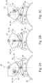
- Fig. 2A-C shows different positions of the direction locking units 81, 82 of Fig. 1 .
- the locking device 80 is in a normal mode for switching between active and off positions.
- the second locking unit 82 is in the active position, where its lock pawl 86 engages with the teeth 88 of the actuator structure 40, particularly the second segment 58.
- the lock pawn 86 is spring-loaded by means of a spring 96 towards the actuator structure 40.
- the actuator structure 40 especially the second segment 58, is bound to an anti-clockwise rotation.
- the first locking unit 81 is in the off position, and the second locking unit 82 is in its off position.
- the off positions of the units 81 and 82 fall together.
- the actuator structure 40 especially the second segment 58 thereof, may rotate clockwise and anti-clockwise.
- the cam disc 87 of the locking device 80 provides a corresponding mechanism for the units 81 and 82 to be moved when the cam disc 87 is pivoted.
- the cam disc 87 thus provides with the control element 90 an interface to move one of the two direction locking units 81 and 82 from its off position in its active position.
- the first locking unit 91 is in the active position, where its lock pawl 86 engages with the teeth 88 of the actuator structure 40, particularly the second segment 58.
- the lock pawn 86 is spring loaded towards the actuator structure 40.
- the actuator structure 40, especially the second segment 58 is bound to a clockwise rotation. This is because the lock pawl 86 of the ratchet means 84 of the first direction locking unit 81 may be pushed out from the teeth 88 in the clockwise rotation and pushed back in from the spring load into the next groove at the teeth 88, while said lock pawl 86 may be fixed in place in an anti-clockwise rotation of the actuator structure 40.
- Fig. 2D the locking device 80 is in a lock mode.
- the active positions of each of the direction locking units 81, 82 are configured to be assumed simultaneously, wherein the control element 90 is positioned in the lock mode, for example starting from the normal mode like shown in Fig. 2A-C , especially starting when in the off positions like shown in Fig. 2C .
- the lock mode being present means that the normal mode is not present.
- the control element 90 is movable along one direction or path, especially by means of the guiding 94, for switching between active and off positions and movable along another direction or path, especially by means of another guiding (not shown), for switching between normal mode (off positions) and lock mode (lock position).
- the cam disc 97 When switching between normal and lock mode (see transition of Fig. 2C to Fig. 2D ), the cam disc 97 may be moved substantially translationally, wherein when switching between active and off positions (see transitions between Figs. 2A-C ), the cam disc 97 may be pivoted.
- the two direction locking units 81, 82 are coupled with the actuator structure 40 to prevent movement in all directions and to fix the actuator structure 40 in place.
- the direction locking units 81, 82 both engage with the teeth 88 simultaneously. It may be that the actuator structure 40 is rotatable/pivotable by +/- 1,5° (overall 3° from one end to another end), when the lock mode is assumed.
- FIG. 3 another construction of a locking device 80 of a spring-loaded actuator 2 is shown in perspective view.
- the locking device 80 is configured to rotate about an actuator axis X in order to rotate an actuator structure 40 of the actuator 2.
- the actuator structure 40 is merely shown in part.
- the locking device 80 may engage by means of its shaft 92 to the actuator structure 40, especially a second segment of the actuator structure 40, in order to rotate the actuator structure 40 between different positions, especially in order to store energy in a spring accumulator (not shown).
- the locking device 80 has two direction locking units 81, 82, namely a first 81 and a second 82 direction locking unit, one for each direction of rotation about an actuator axis X.
- the direction locking units 81, 82 each comprise ratchet means 84 with a spring-loaded lock pawl 96 to engage on teeth 88.
- Each lock pawl 86 has a spring 96 acting on the lock pawl 86 for pushing the lock pawl 86 towards the teeth 88.
- the teeth 88 are formed with curved tips for an enhanced engagement with the lock pawls 86 in one direction and/or for enhanced slipping off from the lock pawls 86 in the other direction.
- the lock pawls 86 are spring loaded to be pushed towards the teeth 88 for an automatic engagement.
- a cam disc 87 is provided for bringing the lock pawls 86 in an off or an active position. As with Figs. 1 and 2 , the off positions fall together and the active positions are in opposing directions to not be assumed simultaneously.
- the cam disc 87 can be operated manually, for example, via a control element 90.
- a hand crank 4 is connected to the locking device 80 for torque transmission.
- the locking device 80 is connected via a shaft 92 for torque transmission with the actuator structure 40.
- Fig. 4A-C shows the locking device 80 of Fig. 3 in different positions.
- the locking device 80 is in an active position of a first locking unit 81 which is configured for allowing a one-way movement of the shaft 92, especially the actuator structure 40, which is in this case a clockwise rotation. An anti-clockwise rotation is thus mechanically blocked by means of the ratchet means 84.
- both locking units 81, 82 allow a free rotation of the shaft 92, especially the teeth 80 attached to the shaft 92 and/or rotationally coupled with the actuator structure 40.
- the locking device 80 is in another active position of a second locking unit 82 which is configured for allowing a one-way movement of the shaft 92, especially the actuator structure 40, which is in this case an anti-clockwise rotation.
- the clockwise rotation is thus mechanically blocked by means of the ratchet means 84.
- Each of the active positions can be achieved by moving, especially rotating, the cam disc 70 such that the cam disc 70 allows the lock pawl 86 to engage with the teeth 88 by the lock pawl 86 being pushed towards the teeth 88 due to its spring-load. Since both lock pawls 86 mechanically interact with the cam disc 70, they can be moved in a coordinated manner between positions.
- the control element 90 is typically guided and movable in a groove at the cam disc 87.
- the control element 90 can be guided in a guiding 94.
- the electrical switching device 1 of Fig. 1 makes possible to conduct a method for operating the spring-loaded actuator 2.
- the method comprises the steps of locking a current direction of movement of the actuator structure 40, and moving, especially rotating, the actuator structure 40 from the first position A to the second position B or from the second position B to the first position A and thereby changing an energy stored within the spring accumulator 70, and optionally unlocking the current direction of movement, especially rotation, of the actuator structure 40.
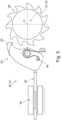
- Fig. 5 shows a locking device 80 with a direction locking unit 81, which unit 81 can block an actuator structure 40 from a rotation in a counter-clockwise direction about an actuator axis X.
- a pivotably mounted lock pawl 86 is actuated by a spring 96, which spring 96 presses the pawl against teeth 88 of a ratchet wheel, particularly coupled with an actuator structure 40 and/or a shaft 90.
- a control element 90 can lift the lock pawl 86 in order to move it to an off position as shown and to stop the function of the direction locking unit 81.
- the control element 90 is guided by a guiding 94.
- the control element 90 can be moved with an actuator, by manual operation, or the like.
- the lock pawl When the actuator structure 40 is in a first A or second B position, which typically correspond to end positions, the lock pawl may be lifted up like shown Fig. 5 to assume the off position.
- the lock pawl 86 When the actuator structure 40 is between the first and second positions A and B, for example in a dead center region C, the lock pawl 86 may be engaging with the teeth 80 for achieving the one-way movement, e.g. when a coupled spring accumulator 90 shall be pre-loaded with energy and/or the first position A shall be assumed by the actuator structure 40 by rotating the shaft 92 and/or the actuator structure 40.
- the lock pawl 86 is activated (in an active position) and interacts with the teeth 88 and prevents the shaft 92 and/or actuator structure 40 from a counter rotation.
Landscapes
- Lock And Its Accessories (AREA)
Abstract
The invention relates to a spring-loaded actuator (2) for an electrical switching device (1), comprising
a driver structure (20) mounted movable and configured to be coupled to the electrical switching device (1) for switching the electrical switching device (1);
an actuator structure (40) mounted movable between a first (A) and a second (B) position and having an engagement section (42) engaging with the driver structure (20);
a spring accumulator (70) coupled to the actuator structure (40) and configured to store energy by means of moving the actuator structure (40) and having a peak in stored energy between the first (A) and the second position (B); and
a locking device (80) configured to allow a one-way movement of the actuator structure (40) from the first (A) or the second (B) position towards the other of the first (A) and the second (B) position.
a driver structure (20) mounted movable and configured to be coupled to the electrical switching device (1) for switching the electrical switching device (1);
an actuator structure (40) mounted movable between a first (A) and a second (B) position and having an engagement section (42) engaging with the driver structure (20);
a spring accumulator (70) coupled to the actuator structure (40) and configured to store energy by means of moving the actuator structure (40) and having a peak in stored energy between the first (A) and the second position (B); and
a locking device (80) configured to allow a one-way movement of the actuator structure (40) from the first (A) or the second (B) position towards the other of the first (A) and the second (B) position.
Description
- The invention relates to a spring-loaded actuator for an electrical switching device, the spring-loaded actuator comprising a driver structure for switching the electrical switching device, an actuator structure engaging with the driver structure, and a spring accumulator configured to store energy by means of moving the actuator structure.
- An electrical switching device, such as a disconnector or earthing switch, also known a grounding switch, is a protective device included in switchgear components like circuit breakers and isolators. When circuit breakers are removed and racked out, earthing switches automatically ground a part of a bus bar adjacent to the circuit breakers. For isolators, the earthing switches make contact with the bus bar when the isolator isolates the circuits, discharging any charges that may have gathered there. For example, an earthing switch in switchgear is used to ground a remaining charge in a power line after the power line has been removed from its source. A residual charge often remains in a circuit after it has been severed or opened by the circuit breaker and isolator. An earthing switch is usually provided to discharge the charge.
- Electrical switching devices often have a snap action closing mechanism for protecting technicians and staff when there is an abnormal current. Generally, electrical switching devices are designed to withstand short circuits. The electrical switching device in a substation has an ability to create short circuits in order to safeguard other electrical devices from damage. The electrical switching device is often used with several high-voltage switchgear and also serves as a protective device in an overhaul of high-voltage electrical equipment.
- Such electrical switching device can be actuated by means of the spring-loaded actuator. The energy stored in the spring accumulator may be used for the switching operation. The spring accumulator may be moved or recharged with energy by a movement of specific parts. When specific parts are moved by means of a motor or by manual operation, end switches must be present for delimit traverse of an operating mechanism being moved. During hand operation defined end positions need to be defined. However, prior art solutions unfortunately do not provide sufficiently secure and easy operation mechanism for moving or recharging such spring-loaded actuators.
- It is therefore an object of the invention to provide solutions for improving the actuation of an electrical switching device.
- The object of the invention is solved by the features of the independent claims. Preferred implementations are detailed in the dependent claims.
- Thus, the object is solved by a spring-loaded actuator for an electrical switching device, comprising
- a driver structure mounted movable and configured to be coupled to the electrical switching device for switching the electrical switching device;
- an actuator structure mounted movable between a first and a second position and having an engagement section engaging with the driver structure;
- a spring accumulator coupled to the actuator structure and configured to store energy by means of moving the actuator structure and having a peak in stored energy between the first and the second position; and
- a locking device configured to allow a one-way movement of the actuator structure from the first or the second position towards the other of the first and the second position.
- The proposed solution thus constitutes an actuator involving a spring load and configured for an electrical switching device. Typically, the actuator has a first movable part for coupling with and switching the electrical switching device. Furthermore, the actuator typically has a second movable part engaging with the first movable part. The actuator particularly has an energy storage based on a spring mechanism and coupled to the second movable part. In that way, a movement of the second part at least indirectly may move and switch the electrical switching device. According to the invention, particularly, a means is provided that merely allows for a one-way movement of the second part from one to another position or the other direction.
- The invention is based on the idea that the actuator structure shall be moved from end to end in order to assure functionality. In practice it has been found that the driver structure may rest in undefined positions when it is not assured that the actuator structure is moved fully from end to end. Thus, the locking device has been implemented in the actuator in order to make sure that the end positions are achieved when the actuator structure is moved.
- The object is furthermore solved by a system comprising an electrical switching device, the spring-loaded actuator as described herein, and at least one movable contact coupled to the driver structure of the spring-loaded actuator.
- The object is furthermore solved by a method for operating a spring-loaded actuator of an electrical switching device, particularly the spring-loaded actuator or electrical switching device as described herein, comprising
- locking a current direction of movement of a movable actuator structure comprised by the spring-loaded actuator,
- moving, especially rotating, the actuator structure from a first position to a second position or vice versa and thereby changing an energy stored within a spring accumulator comprised by the spring-loaded actuator,
- unlocking the current direction of movement of the actuator structure.
- The driver structure typically relates to a component coupled or to be coupled to the electrical switching device (especially directly coupled) in order to realize a switching based on mechanical energy stored in the spring accumulator. The driver structure may be coupled with a pivotable gable to a linearly guided pin of a contact structure. The driver structure may comprise a shaft. The driver structure may be arranged within the actuator structure, especially coaxially therewith.
- The actuator structure typically relates to a component coupled or to be coupled to the spring accumulator (especially directly coupled) in order to act on the spring accumulator. For example, the actuator structure may comprise a lever element that is coupled via a joint to the spring accumulator, especially such that a movement of the actuator structure may realize a change in energy stored in the spring accumulator and/or move the spring accumulator. The actuator structure is typically the interface for triggering the actuator to switch the electrical switching device by means of the actuator. This is due to engagement of the actuator structure with the driver structure.
- The engagement section relates to means for engagement with another section. Engagement or engaged typically translate(s) to motion-coupling or motion-coupled.
- The spring accumulator has at least one spring or compressible means to store mechanical energy. For example, the spring accumulator can be compressed in a substantially straight or linear direction. The spring accumulator is typically held to pivot on one end and to be moved rotationally and/or translationally on another end. When being compressed, the spring accumulator stores energy. When being decompressed, the spring accumulator releases energy. When coupled to a movable, especially rotatable, component on one end and fixed on another end, the spring accumulator may move the component when decompressing and may store energy when the component is moved.
- The peak in stored energy typically relates to a local maximum amount of energy stored relative to adjacent positions or regions. The spring accumulator may assume a maximally compressed arrangement when the peak in stored energy is present. When the peak in stored energy is achieved, typically, the spring accumulator may assume a dead center point with the actuator structure so that the actuator structure can be moved in two opposing directions.
- The term `coupled' typically relates to a mechanical connection, preferably indirectly or directly. Typically, a motion-coupling can be meant. Alternatively or additionally, a fixed attachment can be meant.
- The locking device typically relates to means that serve to lock a direction of movement and thereby merely allowing a one-way movement after the direction of movement is locked, which movement may be translational and/or rotational in nature.
- The first position typically relates to the position of the spring-loaded actuator, especially the actuator structure, where the spring accumulator is charged or preloaded and/or where the electrical switching device may be disconnected.
- The second position typically relates to the position of the spring-loaded actuator, especially the actuator structure, where the spring accumulator is substantially discharged or un-loaded and/or where the electrical switching device may be connected or earthed.
- The term high voltage means preferably a voltage ranging from 36 to 1,100 kV. A high voltage preferably relates to nominal voltages in the range from above 72 kV to 550 kV, like 145 kV, 245 kV or 420 kV, or even more. Nominal currents of the disconnector or earthing switch can be in the range from 1 kA to 5 kA, even high-er such as 80 kA for one second. The conductors can be part of a grid for distribution of said high voltage. The spring-loaded accumulator and/or the electrical switching device is typically configured for high voltage applications.
- In the following, implementations of the invention are described. The implementations may be combined or considered individually. Specific aspects/features described in the context of any of the implementations may be considered individually or in combination. The implementations pursue further optimization of the invention and provide the advantages as described herein.
- In a first preferred implementation the driver structure and/or the actuator structure is/are mounted movable along and/or about an actuator axis. For example, the driver structure and/or the actuator structure may be guided to move along and/or about the actuator axis. The driver structure may be guided with a guiding, e.g. a linear or a rotational guiding and/or bearing. The actuator structure may be guided with a guiding, e.g. a linear or a rotational guiding and/or bearing. The driver structure and/or the actuator structure is/are preferably mounted movable, namely rotatably, especially parallelly, coaxially and/or about the actuator axis. Typically, the driver structure and/or the actuator structure is/are configured for a rotational movement and/or for a rotation.
- The driver structure and the actuator structure may rotate or pivot about the actuator axis, especially coaxially.
- In another implementation the engagement section comprises an actuator element, such as a recess and/or protrusion in particular extending in a radial direction. The actuator element particularly corresponds to a driver element. The driver element may be provided, which driver element may be a recess and/or protrusion in particular extending in the radial direction. The driver element is typically comprised by the driver structure. Preferably, the actuator element and the driver element engage with each other for motion-coupling the driver structure and the actuator structure. A recess may be configured for a protrusion to stop on circumferential ends of the recess. The actuator element and driver element form, preferably along or about a movement axis of the actuator structure, particularly the actuator axis, a clearance. For example, the recess in combination with a protrusion may provide a play or clearance or backlash between driver structure and actuator structure.
- In another implementation the spring accumulator assumes the peak in stored energy when the actuator structure is in a dead center region. In the dead center region, the actuator structure may be pushed by the spring accumulator in substantially no direction and/or may be pushed by the spring accumulator to stop in the dead center region. It may be provided that, when moving from the first towards or to the second position and when the actuator structure reaches the dead center region and, the driver structure is entrained by and/or mechanically contacts the actuator structure towards the second position in order to switch the electrical switching device. In other words, for example, the actuator is designed such that a movement of the actuator structure from end to end would be such that in an intermediate position the driver structure is mechanically carried along until the other end. This ensures a reliable and quick switching. The dead center region may make up to 5 % or up to 10 % of the movement between the first and second positions.
- In another implementation the locking device comprising at least one direction locking unit configured to be coupled to the actuator structure and to allow the one-way movement from the first position towards the second position or from the second position towards the first position when coupled to the actuator structure. The at least one direction locking unit is movable between an active and an off position and coupled to the actuator structure in the active position and uncoupled in the off position. In other words, the direction locking unit can be selectively coupled to the actuator structure in order to allow the one-way movement. The direction locking unit can be activated and deactivated by a movement into corresponding positions. For example, the actuator may be constructed such that the actuator structure can only be moved or rotated when the direction locking unit is in an/the active position. For example, a cam disc of the locking device may be provided that may interact with the direction locking unit(s) when being pivoted, for example to move the direction locking unit(s) between positions. This enhances safety.
- In another implementation the at least one direction locking unit has a ratchet means configured to engage with teeth comprised by the locking device and coupled to the actuator structure. The ratchet means may have a lock pawl movable between the off and active positions and/or wherein may be spring-loaded to automatically engage with the teeth. The ratchet means may comprise engagement means or the lock pawl for engaging with the teeth of the locking device. The engagement means or lock pawl may be pushed by spring load to engage with the teeth. The teeth are typically a section of the actuator structure. The engagement means or lock pawl may be pivotable between off and active positions.
- In another implementation the locking device has a control element configured to move the at least one direction locking unit between the off and active position(s), especially against a/the spring-load acting on the ratchet means. The control element may be a switch or knob especially for manual operation. The control element may be configured for a translational and/or rotational movement.
- In another implementation the off positions of each of the at least one direction locking unit overlap so that all off positions can be assumed at a time. Thus, it can be assured that the direction locking units are both switched off in the case one is switched off. The construction can be realized, for example, in that both direction locking units are operated with the same control element.
- Alternatively or additionally the active positions of each of the at least one direction locking unit are aligned oppositely so that only one active position can be assumed at a time, especially in a normal mode of the locking device. The active positions may exclude each other, especially in a/the normal mode of the locking device. For example, when one active position is selected another active position is not possible to be assumed, especially in the normal mode. This can also be realized, for example, in that both direction locking units are operated with the same control element.
- Particularly, the locking device may assume the normal mode for switching between off and active position(s). The locking device may assume a lock mode which is different from the normal mode and/or which is configured to prohibit any movement and/or one-way movement of the actuator structure, especially from the first or the second position towards the other of the first and the second position. The lock mode may be that all active positions are assumed concurrently. Switching between lock mode and normal mode may require a translational and/or rotational movement of the locking device, especially starting from the off position(s).
- It may be that the active positions of each of the at least one direction locking units are configured to be assumed simultaneously in a/the lock mode of the locking device, especially wherein the control element can be moved to/into the lock mode, for example starting from a/the normal mode. The normal mode may be understood to be present when the lock mode is not present, and/or vice versa. For example, the control element may be movable along one direction or path for switching between active and off positions and movable along another direction or path for switching between normal mode, especially off position(s), and lock mode, especially lock position.
- Particularly, when in the lock mode and/or the lock mode is assumed, all direction locking units are coupled with the actuator structure to prevent movement in all directions and/or to fix the actuator structure in place. Optionally, it may be that the actuator structure is rotatable/pivotable by +/- 6°, +/- 3° or +/- 1,5° when the lock mode is assumed.
- In another implementation the actuator structure has a first segment coupled to the spring accumulator and a second segment movably coupled to and forming a play with the first segment. The first segment and the second segment may be movable along and/or around the actuator axis, especially coaxially, especially rotatably. The first and second segments may be provided engaging with each other including a play and/or a backlash. The first and second segments may engage via segment elements especially forming the play/backlash. The segment elements may be a protrusion and/or a recess. The play/backlash may be provided so that the first segment may move at least within the play independently from the second segment, for example to reduce friction and/or realize a freewheel mechanism for the first segment, especially while the second segment may be engaged elsewhere, like a drive unit. Particularly, the first segment is meant to assume the first position, second position and/or dead center region. Particularly, the spring accumulator is coupled directly to the first and/or to the second segment, especially only to the first segment of the segments.
- Alternatively or additionally a drive unit may be provided, which drive unit is coupled to the actuator structure, especially including a play. The drive unit is preferably configured to move/rotate/actuate the actuator structure to/towards the dead center region, to the first position and/or to the second position. The drive unit may be able to move the actuator structure between the first and second positions especially via the dead center region. The drive unit may be an actuator and/or a motor, especially driven by electricity. The drive unit may engage directly on the actuator structure, especially on the first and/or on the second segment. The drive unit may engage on a lever formed with the actuator structure. The lever may be formed directly on the first and/or on the second segment of the actuator structure.
- The drive unit may engage, especially rotationally, with the actuator structure, especially with the first segment and/or with the second segment thereof. The drive unit may serve to automatically bring the actuator structure to actuate on the electrical switching device by moving the actuator structure. For example, the drive unit may be configured to move the actuator structure from the first position to the dead center region where the driver structure is then also moved; then, the spring accumulator may unload stored energy which results in a further movement of the actuator structure to the second position including a further movement of the driver structure that actuates on the electrical switching device. The drive unit may as well be configured to bring back the actuator structure from the second position - especially via the dead center region - to the first position, which of course may include a back-movement of the driver structure.
- In another implementation the actuator structure has a connector for connecting with a hand crank in order to manually move the actuator structure between the first and the second position. The connector may be a free end of a shaft. The hand crank may comprise a socket for connection with the connector and/or the free end. The connector provides an option for a manual operation and/or setback of the actuator.
- Preferably, (the actuator may be configured such that) in the off position(s) the connector is blocked, for example by means of a movable blocking element comprised by the locking device and/or in order to prohibit a connection with the hand crank. The movable locking element may be actuated by and/or motion-coupled with the actuator structure. Alternatively or additionally, (the actuator may be configured such that) in the active position(s) and/or between the first and second position the connector is unblocked in order to enable a/the connection with the hand crank. This enhances safety.
- In another implementation the locking device has a crank locking means configured for locking the connected hand crank against disconnecting the hand crank especially between the first and the second position. The crank locking means may be actuated by and/or motion-coupled with the actuator structure. Alternatively or additionally, (the actuator may be configured such that) in the active position(s) and/or between the first and second position the hand crank is locked in order to secure the hand crank in place. The crank locking means may be formed by the blocking element. This enhances safety.
- For example, the blocking element and/or the crank locking means may be actuated by a cam plate or cam disc especially mounted or formed with the actuator structure. Said cam plate or cam disc may move together with the movement of the actuator structure.
- The term 'or' is not meant limiting in that mere alternatives are mentioned, but may rather be replaced by 'and/or' in any case.
- These and other aspects of the invention will be apparent from and elucidated with reference to the implementations described hereinafter.
- In the drawings:
-
Fig. 1 shows a system with an electrical switching device, a movable contact and a spring-loaded actuator which is coupled to the movable contact in a schematic overview; -
Fig. 2A-D shows the locking device of the spring-loaded actuator ofFig. 1 with two locking units, where a first locking unit is in an active position (C), where both locking units are in an off position (B), where a second locking unit is in an active position (A), and where the locking device is in a lock mode (D) in a schematic overview; -
Fig. 3 shows another embodiment of a spring-loaded actuator with a locking device including two direction locking units each with ratchet means in a perspective view; -
Fig. 4A-C shows the locking device ofFig. 3 in different positions in a side view; and -
Fig. 5 shows another locking device for a spring-loaded actuator for an electrical switching device in a side view. - The description contains procedural or methodical aspects upon describing structural features of the claimed invention; the structural features can be understood well in that way. It is emphasized to the reader that such structural features can be lifted from the described context without hesitation or the question of an intermediate generalization to form aspects of the invention. It is also emphasized to the reader that any the structural features described in the following can be understood as individual aspects of the invention to distinguish from known solutions, despite being possibly lifted from the context.
- In
Fig. 1 a system with an electrical switching device 1 and a spring-loaded actuator 2 is shown. The electrical switching device 1 is coupled to the spring-loaded actuator 2. Acontact 8 can be moved by means of the actuator 2, especially by means of energy stored in aspring accumulator 70 of the actuator 2. - The actuator 2 comprises a
driver structure 20 mounted movable and coupled to the electrical switching device 1 for switching the electrical switching device 1. The actuator 2 furthermore comprises an actuator structure 40 mounted movable between a first A and a second B position. The actuator structure 40 has an engagement section 42 engaging with thedriver structure 20. - The
spring accumulator 70 is coupled with a joint on one end to alever element 46 formed at theactuator structure 20 and configured to store energy by means of moving or rotating theactuator structure 20. Another end of thespring accumulator 70 is pivotably or rotatably held. Thespring accumulator 70 is arranged in order to have a peak in stored energy between the first position A and the second position B. - The actuator 2 also has a
locking device 80 configured to allow a one-way movement of theactuator structure 20 from the first A or the second B position towards the other of the first A and the second B position. - The
driver structure 20 and the actuator structure 40 are mounted movable, i.e. rotatable, about an actuator axis X. Particularly, a rotational bearing is provided for thestructure 20 and/or 40. Thestructures 20 and 40 are mounted rotatably coaxially about the actuator axis X. Thedriver structure 20 and the actuator structure 40 may thus rotate, especially pivot, about the actuator axis X. - The engagement section 42 comprises an actuator element 44 formed with a recess extending in a radial direction R especially with respect to the axis X. The actuator element 44 particularly corresponds to a
driver element 24. - The
driver structure 20 has thedriver element 24 which corresponds to the actuator element 44. Thedriver element 24 is formed with a protrusion extending in the radial direction R. Thedriver element 24 and theactuator element 4 engage with each other for motion-coupling thedriver structure 20 and the actuator structure 40. The actuator element 44 is configured for thedriver element 24 to stop on circumferential ends of the actuator element 44. Theelements 24 and 44 form about the actuator axis X a clearance 3. - The
spring accumulator 70 assumes the peak in stored energy when the actuator structure 40 is in a dead center region C. In the dead center region C, the actuator structure 40 can be pushed by thespring accumulator 70 in substantially no direction and may be pushed to stop in the dead center region C. - Particularly, the first position A, the second position B, and the dead center region C are arranged on a curve, particularly a circular curve and/or about the axis X.
- It is provided that, when moving from the first A towards or to the second B position and when the actuator structure 40 reaches the dead center region C and, the
driver structure 20 is entrained by and mechanically contacts the actuator structure 40 towards the second position B in order to switch the electrical switching device 1. The actuator 2 is designed such that in a movement of the actuator structure 40 from one end position (first position A) to another end (second position B) actuator structure 40 goes along an intermediate position (dead center region C) where thedriver structure 20 is mechanically contacted and/or carried along until the other end (second position B). The dead center region C makes approx. 5 to 10 % of the angle and/or distance between the first A and second positions B. - When moving the actuator structure 40 from the first position A towards the second position B, switching may only take place only when the actuator structure 40 is moved sufficiently above a dead center in the dead center region C so that the torque, which results from the force of the
spring accumulator 70 and the resulting lever arm, can overcome the friction prevailing. Due to the friction present in the joints, it is not necessary to speak of a dead center, but rather of a range in which there is an inherent inhibition, i.e. the dead center region C. - The locking
device 80 comprises twodirection locking units - A first
direction locking unit 81 of the twodirection locking units - A second
direction locking unit 82 of the twodirection locking units - Each of the two
direction locking units direction locking units cam disc 87 of thelocking device 80 is provided that interacts with thedirection locking units direction locking units - The
direction locking units teeth 88 of thelocking device 80 when in an/the active position. Each ratchet means 84 has alock pawl 86 pivotable between the off and active position. The lock pawls 86 are spring-loaded by aspring 96 to automatically engage, particularly re-engage, with theteeth 88. Theteeth 88 are external teeth or gearings. Theteeth 88 are a section of the actuator structure 40. Particularly, the lock pawl(s) 86 and/orcam disc 87 may pivot in parallel to the actuator axis X. - For example, when the
lock pawl 86 of the firstdirection locking unit 81 is in the active position as shown inFig. 1 , the actuator structure 40 may merely rotate anti-clockwise, wherein during an anti-clockwise rotation of the actuator structure 40 saidlock pawl 86 will be repetitively pushed out from theteeth 88 and re-engage with theteeth 88. In contrast, when applying a torque to the actuator structure 40 about the actuator axis X for a desired rotation of the actuator structure 40 in a clockwise direction, saidlock pawl 86 will prohibit/block the actuator structure 40 from moving in the clockwise direction. - The locking
device 80 has acontrol element 90 in the form of a switch or knob configured to move thedirection locking units control element 90 is furthermore guided along a guiding 94 for a substantially linear movement of thecontrol element 90 which facilitates easy manual operation. - Here, the off positions of each of the
direction locking units direction locking units same control element 90. - The active positions of each of the
direction locking units Fig. 1 , when the active position of the firstdirection locking unit 81 is selected the active position of the seconddirection locking unit 82 is not possible to be assumed. - The actuator structure 40 has a
first segment 56 coupled to thespring accumulator 70 and asecond segment 58 movably coupled to and forming a play 12 with thefirst segment 56. Thefirst segment 56 and thesecond segment 58 are arranged to coaxially rotate about the actuator axis X. Thefirst segment 56 is meant to assume the first position A, second position B and dead center region C. Thespring accumulator 70 is coupled directly only to thefirst segment 56 of the twosegments - The first 56 and
second segments 58 engage with each other including the play 12 as a backlash. A first segment element 60 of thefirst segment 56 comprises a protrusion. A second segment element 62 of thesecond segment 58 comprises a recess, e.g. a groove, wherein the segment elements 60 and 62 together constitute the play 12. - The play 12 is provided so that the first segment 52 can move within the play 12 substantially independently from the
second segment 56 to reduce friction when actuating and realize a freewheel mechanism for thefirst segment 56 while the second segment is engaged with adrive unit 10 and/or thelocking device 80. - The
second segment 58 is configured for engagement with the lockingdevice 80 especially as follows. The lockingunits teeth 88 to thesecond segment 58 for allowing the one-way movement of the actuator structure 40, especially aside from the play 12. - The
drive unit 10 is coupled via a gear especially engaging on theteeth 88 at thesecond segment 58 of the actuator structure 40. The play 12 is included for thedrive unit 10 relative to thefirst segment 56. Thedrive unit 10 is configured to move the actuator structure 40 to the dead center region C, to the second position B, and back to the first position A. Thedrive unit 10 can move the actuator structure 40 between the first A and second B positions via the dead center region C. Thedrive unit 10 has an electrical motor. - The
drive unit 10 engages rotationally with the actuator structure 40, especially with thesecond segment 58. Thedrive unit 10 can bring the actuator structure 40 to actuate on the electrical switching device 1 by moving thefirst segment 56 of the actuator structure 40. Thedrive unit 10 can move the actuator structure 40 from the first position A to the dead center region C from where on thedriver structure 20 is also being moved until the second position B. When in the dead center region C, especially at the end thereof towards the second position B, thespring accumulator 70 will unload stored energy which results in a further movement of the actuator structure 40 to the second position B including a further movement of thedriver structure 20 that actuates on the electrical switching device 1 via a gable. The gable may guide a pin of thecontact 8 in order to close or open an electrical connection by pushing thecontact 8 into another contact, especially a tulip contact, or pulling thecontact 8 out. - The
drive unit 10 can bring back the actuator structure 40 from the second position B via the dead center region C to the first position A which includes a back-movement of thedriver structure 20 and thus another actuation of the electrical switching device 1. - The actuator structure 40 has a
connector 48 for connecting with a hand crank 4 in order to manually move the actuator structure 40 between the first A and the second B position. Theconnector 48 is formed at a free end of a shaft. The hand crank 4 has a socket for connection with theconnector 48 configured for torque transmission. - The
connector 48 can be blocked by means of a movable blocking element 50 in order to prohibit a connection with the hand crank 4. The movable locking element 50 can be actuated by and is motion-coupled to the actuator structure 40. - The locking
device 80 has a crank locking means 52 configured for locking the connected hand crank 4 against disconnecting the hand crank 4 especially between the first A and the second B position. The crank locking means 52 is actuated by and is motion-coupled to the actuator structure 40. Between the first A and second B position the hand crank 4 is locked in order to secure the hand crank 4 in place. The crank locking means 52 is formed by the blocking element 50. - The blocking element 50 and the crank locking means 52 are configured to be actuated by a
cam disc 54 mounted or formed with the actuator structure 40. -
Fig. 2A-C shows different positions of thedirection locking units Fig. 1 . InFig. 2A-C the lockingdevice 80 is in a normal mode for switching between active and off positions. InFig. 2A thesecond locking unit 82 is in the active position, where itslock pawl 86 engages with theteeth 88 of the actuator structure 40, particularly thesecond segment 58. Thelock pawn 86 is spring-loaded by means of aspring 96 towards the actuator structure 40. In the active position of thesecond locking unit 82 the actuator structure 40, especially thesecond segment 58, is bound to an anti-clockwise rotation. This is because thelock pawl 86 of the ratchet means 84 of the seconddirection locking unit 82 may be pushed out from theteeth 88 in the anti-clockwise rotation and pushed back in from the spring load into the next groove at theteeth 88, while saidlock pawl 86 may be fixed in place in a clockwise rotation of the actuator structure 40. - In
Fig. 2B thefirst locking unit 81 is in the off position, and thesecond locking unit 82 is in its off position. The off positions of theunits Fig. 2B , the actuator structure 40, especially thesecond segment 58 thereof, may rotate clockwise and anti-clockwise. - It can be seen that the
cam disc 87 of thelocking device 80 provides a corresponding mechanism for theunits cam disc 87 is pivoted. Thecam disc 87 thus provides with thecontrol element 90 an interface to move one of the twodirection locking units - In
Fig. 2C the first locking unit 91 is in the active position, where itslock pawl 86 engages with theteeth 88 of the actuator structure 40, particularly thesecond segment 58. Thelock pawn 86 is spring loaded towards the actuator structure 40. In the active position of thefirst locking unit 81 the actuator structure 40, especially thesecond segment 58, is bound to a clockwise rotation. This is because thelock pawl 86 of the ratchet means 84 of the firstdirection locking unit 81 may be pushed out from theteeth 88 in the clockwise rotation and pushed back in from the spring load into the next groove at theteeth 88, while saidlock pawl 86 may be fixed in place in an anti-clockwise rotation of the actuator structure 40. - In
Fig. 2D thelocking device 80 is in a lock mode. Here, the active positions of each of thedirection locking units control element 90 is positioned in the lock mode, for example starting from the normal mode like shown inFig. 2A-C , especially starting when in the off positions like shown inFig. 2C . The lock mode being present means that the normal mode is not present. Thecontrol element 90 is movable along one direction or path, especially by means of the guiding 94, for switching between active and off positions and movable along another direction or path, especially by means of another guiding (not shown), for switching between normal mode (off positions) and lock mode (lock position). - When switching between normal and lock mode (see transition of
Fig. 2C to Fig. 2D ), the cam disc 97 may be moved substantially translationally, wherein when switching between active and off positions (see transitions betweenFigs. 2A-C ), the cam disc 97 may be pivoted. - In the lock mode as shown in
Fig. 2D , the twodirection locking units direction locking units teeth 88 simultaneously. It may be that the actuator structure 40 is rotatable/pivotable by +/- 1,5° (overall 3° from one end to another end), when the lock mode is assumed. - In
Fig. 3 another construction of alocking device 80 of a spring-loaded actuator 2 is shown in perspective view. The lockingdevice 80 is configured to rotate about an actuator axis X in order to rotate an actuator structure 40 of the actuator 2. The actuator structure 40 is merely shown in part. For example, the lockingdevice 80 may engage by means of itsshaft 92 to the actuator structure 40, especially a second segment of the actuator structure 40, in order to rotate the actuator structure 40 between different positions, especially in order to store energy in a spring accumulator (not shown). - The locking
device 80 has twodirection locking units direction locking units lock pawl 96 to engage onteeth 88. Eachlock pawl 86 has aspring 96 acting on thelock pawl 86 for pushing thelock pawl 86 towards theteeth 88. - The
teeth 88 are formed with curved tips for an enhanced engagement with thelock pawls 86 in one direction and/or for enhanced slipping off from thelock pawls 86 in the other direction. In this case, thelock pawls 86 are spring loaded to be pushed towards theteeth 88 for an automatic engagement. - A
cam disc 87 is provided for bringing thelock pawls 86 in an off or an active position. As withFigs. 1 and2 , the off positions fall together and the active positions are in opposing directions to not be assumed simultaneously. Thecam disc 87 can be operated manually, for example, via acontrol element 90. - A hand crank 4 is connected to the
locking device 80 for torque transmission. The lockingdevice 80 is connected via ashaft 92 for torque transmission with the actuator structure 40. -
Fig. 4A-C shows thelocking device 80 ofFig. 3 in different positions. InFig. 4A , the lockingdevice 80 is in an active position of afirst locking unit 81 which is configured for allowing a one-way movement of theshaft 92, especially the actuator structure 40, which is in this case a clockwise rotation. An anti-clockwise rotation is thus mechanically blocked by means of the ratchet means 84. - In
Fig. 4B , the lockingdevice 80 is in an off position. In this position, both lockingunits shaft 92, especially theteeth 80 attached to theshaft 92 and/or rotationally coupled with the actuator structure 40. - In
Fig. 4C , the lockingdevice 80 is in another active position of asecond locking unit 82 which is configured for allowing a one-way movement of theshaft 92, especially the actuator structure 40, which is in this case an anti-clockwise rotation. The clockwise rotation is thus mechanically blocked by means of the ratchet means 84. - Each of the active positions can be achieved by moving, especially rotating, the
cam disc 70 such that thecam disc 70 allows thelock pawl 86 to engage with theteeth 88 by thelock pawl 86 being pushed towards theteeth 88 due to its spring-load. Since both lockpawls 86 mechanically interact with thecam disc 70, they can be moved in a coordinated manner between positions. - The
control element 90 is typically guided and movable in a groove at thecam disc 87. Thecontrol element 90 can be guided in a guiding 94. - The electrical switching device 1 of
Fig. 1 makes possible to conduct a method for operating the spring-loaded actuator 2. The method comprises the steps of locking a current direction of movement of the actuator structure 40, and moving, especially rotating, the actuator structure 40 from the first position A to the second position B or from the second position B to the first position A and thereby changing an energy stored within thespring accumulator 70, and optionally unlocking the current direction of movement, especially rotation, of the actuator structure 40. -
Fig. 5 shows alocking device 80 with adirection locking unit 81, whichunit 81 can block an actuator structure 40 from a rotation in a counter-clockwise direction about an actuator axis X. - A pivotably mounted
lock pawl 86 is actuated by aspring 96, which spring 96 presses the pawl againstteeth 88 of a ratchet wheel, particularly coupled with an actuator structure 40 and/or ashaft 90. - A
control element 90 can lift thelock pawl 86 in order to move it to an off position as shown and to stop the function of thedirection locking unit 81. Thecontrol element 90 is guided by a guiding 94. Thecontrol element 90 can be moved with an actuator, by manual operation, or the like. - When the actuator structure 40 is in a first A or second B position, which typically correspond to end positions, the lock pawl may be lifted up like shown
Fig. 5 to assume the off position. When the actuator structure 40 is between the first and second positions A and B, for example in a dead center region C, thelock pawl 86 may be engaging with theteeth 80 for achieving the one-way movement, e.g. when a coupledspring accumulator 90 shall be pre-loaded with energy and/or the first position A shall be assumed by the actuator structure 40 by rotating theshaft 92 and/or the actuator structure 40. In this case, thelock pawl 86 is activated (in an active position) and interacts with theteeth 88 and prevents theshaft 92 and/or actuator structure 40 from a counter rotation. This works for example as an installation of an interlock which activates thelock pawl 86 as soon as the actuator structure 40 is rotated and is only deactivated again when the actuator structure 40 has reached an end position, for example first position A or second position B, but especially not the dead center region C. -
- 1
- electrical switching device
- 2
- actuator
- 3
- clearance
- 4
- hand crank
- 8
- contact
- 10
- drive unit
- 12
- play
- 20
- driver structure
- 24
- driver element
- 40
- actuator structure
- 42
- engagement section
- 44
- actuator element
- 46
- lever element
- 48
- connector
- 50
- blocking element
- 52
- crank locking means
- 54
- cam disc
- 56
- first segment
- 58
- second segment
- 60
- segment element
- 62
- segment element
- 70
- spring accumulator
- 80
- locking device
- 81
- direction locking unit
- 82
- direction locking unit
- 84
- ratchet means
- 86
- lock pawl
- 87
- cam disc
- 88
- teeth
- 90
- control element
- 92
- shaft
- 94
- guiding
- 96
- spring
- A
- first position
- B
- second position
- C
- dead center region
- R
- radial direction
- X
- actuator axis
Claims (15)
- Spring-loaded actuator (2) for an electrical switching device (1), comprisinga driver structure (20) mounted movable and configured to be coupled to the electrical switching device (1) for switching the electrical switching device (1);an actuator structure (40) mounted movable between a first (A) and a second (B) position and having an engagement section (42) engaging with the driver structure (20);a spring accumulator (70) coupled to the actuator structure (40) and configured to store energy by means of moving the actuator structure (40) and having a peak in stored energy between the first (A) and the second position (B); anda locking device (80) configured to allow a one-way movement of the actuator structure (40) from the first (A) or the second (B) position towards the other of the first (A) and the second (B) position.
- Spring-loaded actuator (2) according to the preceding claim, wherein the driver structure (20) and/or the actuator structure (40) is/are mounted movable along and/or about an actuator axis (X).
- Spring-loaded actuator (2) according to one of the preceding claims, wherein the driver structure (20) and/or the actuator structure (40) is/are mounted movable, namely rotatably, especially parallelly, coaxially and/or about the actuator axis (X).
- Spring-loaded actuator (2) according to one of the preceding claims, wherein the engagement section (42) comprises an actuator element (44), such as a recess and/or protrusion in particular extending in a radial direction (R), corresponding to a driver element (24), such as a recess and/or protrusion in particular extending in the radial direction (R), of the driver structure (20).
- Spring-loaded actuator (2) according to one of the preceding claims, wherein the actuator element (44) and driver element (24) form along or about a movement axis of the actuator structure (40), particularly the actuator axis (X), a clearance (3).
- Spring-loaded actuator (2) according to one of the preceding claims, wherein the spring accumulator (70) assumes the peak in stored energy when the actuator structure (40) is in a dead center region (C),
wherein, when moving from the first (A) towards or to the second position (B) and when the actuator structure (40) reaches the dead center region (C) and, the driver structure (20) is entrained by and/or mechanically contacts the actuator structure (40) towards the second position (B) in order to switch the electrical switching device (1). - Spring-loaded actuator (2) according to one of the preceding claims, whereinthe locking device (80) comprising at least one direction locking unit (81, 82) configured to be coupled to the actuator structure (40) and to allow the one-way movement from the first position (A) towards the second position (B) or from the second position (B) towards the first position (A) when coupled to the actuator structure (40), particularlythe at least one direction locking unit (81, 82) movable between an active and an off position and coupled to the actuator structure (40) in the active position and uncoupled in the off position.
- Spring-loaded actuator (2) according to the preceding claim, wherein
the at least one direction locking unit (81, 82) has a ratchet means (84) configured to engage with teeth (88) comprised by the locking device (80) and coupled to the actuator structure (40), particularly wherein the ratchet means (84) has a lock pawl (86) movable between the off and active positions and/or wherein the ratchet means (84) is spring-loaded to automatically engage with the teeth (88). - Spring-loaded actuator (2) according to one of the preceding two claims, wherein
the locking device (80) has a control element (90) configured to move the at least one direction locking unit (81, 82) between the off and active position(s), especially against a/the spring-load acting on the ratchet means (84). - Spring-loaded actuator (2) according to one of the preceding three claims, whereinthe off positions of each of the at least one direction locking unit (81, 82) overlap so that all off positions can be assumed at a time, and/orthe active positions of each of the at least one direction locking unit (81, 82) are aligned oppositely so that only one active position can be assumed at a time, and/orthe active positions of each of the at least one direction locking units (81, 82) are configured to be assumed simultaneously in a lock mode of the locking device (80), especially wherein the control element (90) can be moved to the lock mode.
- Spring-loaded actuator (2) according to one of the preceding claims,wherein the actuator structure (40) has a first segment (56) coupled to the spring accumulator (70) and a second segment (58) movably coupled to and forming a play (12) with the first segment (56), the second segment (58) configured for engagement with the locking device (80) and/orcomprising a drive unit (10) coupled to the actuator structure (40), especially to the second segment (58), and configured to move the actuator structure (40) to the dead center region (C), to the first position (A) and/or to the second position (B).
- Spring-loaded actuator (2) according to one of the preceding claims, whereinthe actuator structure (40) has a connector (48) for connecting with a hand crank in order to manually move the actuator structure (40) between the first (A) and the second position (B), especially whereinin the off position(s) the connector (48) is blocked by means of a movable blocking element (50) comprised by the locking device (80) and in order to prohibit a connection with the hand crank, and/or in the active position(s) the connector (48) is unblocked in order to enable a/the connection with the hand crank.
- Spring-loaded actuator (2) according to one of the preceding claims, wherein
the locking device (80) has a crank locking means (52) configured for locking the connected hand crank against disconnecting the hand crank especially between the first (A) and the second position (B). - System comprising an electrical switching device (1), the spring-loaded actuator (2) according to one of the preceding claims, and at least one movable contact (8) coupled to the driver structure (20) of the spring-loaded actuator (2).
- Method for operating a spring-loaded actuator (2) of an electrical switching device (1), particularly according to the preceding claim, comprisinglocking a current direction of movement of a movable actuator structure (40) comprised by the spring-loaded actuator (2),moving, especially rotating, the actuator structure (40) from a first position (A) to a second position (B) or vice versa and thereby changing an energy stored within a spring accumulator (70) comprised by the spring-loaded actuator (2),unlocking the current direction of movement of the actuator structure (40).
Priority Applications (3)
| Application Number | Priority Date | Filing Date | Title |
|---|---|---|---|
| EP23191099.3A EP4506974A1 (en) | 2023-08-11 | 2023-08-11 | Actuator for an electrical switching device, electrical switching device and method |
| CN202480052909.3A CN121729753A (en) | 2023-08-11 | 2024-08-09 | Actuator for an electrical switching apparatus, electrical switching apparatus and method |
| PCT/EP2024/072646 WO2025036855A1 (en) | 2023-08-11 | 2024-08-09 | Actuator for an electrical switching device, electrical switching device and method |
Applications Claiming Priority (1)
| Application Number | Priority Date | Filing Date | Title |
|---|---|---|---|
| EP23191099.3A EP4506974A1 (en) | 2023-08-11 | 2023-08-11 | Actuator for an electrical switching device, electrical switching device and method |
Publications (1)
| Publication Number | Publication Date |
|---|---|
| EP4506974A1 true EP4506974A1 (en) | 2025-02-12 |
Family
ID=87571075
Family Applications (1)
| Application Number | Title | Priority Date | Filing Date |
|---|---|---|---|
| EP23191099.3A Pending EP4506974A1 (en) | 2023-08-11 | 2023-08-11 | Actuator for an electrical switching device, electrical switching device and method |
Country Status (3)
| Country | Link |
|---|---|
| EP (1) | EP4506974A1 (en) |
| CN (1) | CN121729753A (en) |
| WO (1) | WO2025036855A1 (en) |
Citations (2)
| Publication number | Priority date | Publication date | Assignee | Title |
|---|---|---|---|---|
| US20130062175A1 (en) * | 2011-09-08 | 2013-03-14 | Timothy Gordon Robirds | Electrical switching apparatus, and stored energy assembly and energy storage and release control mechanism therefor |
| EP3282464A1 (en) * | 2016-08-09 | 2018-02-14 | Siemens Aktiengesellschaft | Jump drive and switching device with jump drive |
-
2023
- 2023-08-11 EP EP23191099.3A patent/EP4506974A1/en active Pending
-
2024
- 2024-08-09 CN CN202480052909.3A patent/CN121729753A/en active Pending
- 2024-08-09 WO PCT/EP2024/072646 patent/WO2025036855A1/en active Pending
Patent Citations (2)
| Publication number | Priority date | Publication date | Assignee | Title |
|---|---|---|---|---|
| US20130062175A1 (en) * | 2011-09-08 | 2013-03-14 | Timothy Gordon Robirds | Electrical switching apparatus, and stored energy assembly and energy storage and release control mechanism therefor |
| EP3282464A1 (en) * | 2016-08-09 | 2018-02-14 | Siemens Aktiengesellschaft | Jump drive and switching device with jump drive |
Also Published As
| Publication number | Publication date |
|---|---|
| CN121729753A (en) | 2026-03-24 |
| WO2025036855A1 (en) | 2025-02-20 |
Similar Documents
| Publication | Publication Date | Title |
|---|---|---|
| US9875868B2 (en) | Locking device for high-voltage switchgear | |
| JP5070178B2 (en) | Switchgear | |
| US5859398A (en) | Sequential isolating circuit breaker and actuator | |
| WO2025036855A1 (en) | Actuator for an electrical switching device, electrical switching device and method | |
| EP3089186B1 (en) | Electrical switchgear and method of operating an electrical switchgear | |
| US6989498B1 (en) | Method and device for locking | |
| EP3482408B1 (en) | Fast earthing switch device for hv applications | |
| DE102008011522B4 (en) | Slide-in switching device for insertion into a slide-in cassette of a control cabinet and for use with a low voltage or medium voltage | |
| CN1257294A (en) | Electric equipment with transformer, unloading connector converter and load switching off device | |
| US7091432B2 (en) | Power circuit breaker | |
| EP4616441A1 (en) | Operating mechanism for a switchgear device | |
| GB2311654A (en) | Circuit breaker with recloser | |
| US20240203670A1 (en) | Disconnector or earthing switch | |
| EP2093780A1 (en) | A spring drive unit, an operating device for an electrical switching apparatus, and method for charging and/or discharging a spring in an operating device for an electrical switching apparatus | |
| EP4411767A1 (en) | An actuation unit for a switching apparatus | |
| US20190157017A1 (en) | Drive system for high-voltage electrical devices | |
| CA2788790C (en) | Electrical switching apparatus, and stored energy assembly and energy storage and release control mechanism therefor | |
| CN118213224B (en) | Interlocking device, system and operation method suitable for power switch | |
| EP4411768A1 (en) | An actuation unit for a switching apparatus | |
| KR102687191B1 (en) | Load breaker switch gearbox and ring main unit having the same | |
| KR200301490Y1 (en) | Disconnector Safety Device of Gas Insulated Switch-gear | |
| KR200342733Y1 (en) | Opening and closing drive mechanism of vacuum circuit breaker for gas insulated switchgear | |
| KR20230127010A (en) | Interlock Device between Disconnector and High Speed Earthing Switch | |
| KR100584826B1 (en) | Trigger device of high pressure equipment | |
| WO2023101631A1 (en) | A disconnector mechanism |
Legal Events
| Date | Code | Title | Description |
|---|---|---|---|
| PUAI | Public reference made under article 153(3) epc to a published international application that has entered the european phase |
Free format text: ORIGINAL CODE: 0009012 |
|
| STAA | Information on the status of an ep patent application or granted ep patent |
Free format text: STATUS: THE APPLICATION HAS BEEN PUBLISHED |
|
| AK | Designated contracting states |
Kind code of ref document: A1 Designated state(s): AL AT BE BG CH CY CZ DE DK EE ES FI FR GB GR HR HU IE IS IT LI LT LU LV MC ME MK MT NL NO PL PT RO RS SE SI SK SM TR |
|
| STAA | Information on the status of an ep patent application or granted ep patent |
Free format text: STATUS: REQUEST FOR EXAMINATION WAS MADE |
|
| 17P | Request for examination filed |
Effective date: 20250811 |