EP4506971A1 - Stationary induction apparatus - Google Patents
Stationary induction apparatus Download PDFInfo
- Publication number
- EP4506971A1 EP4506971A1 EP22936525.9A EP22936525A EP4506971A1 EP 4506971 A1 EP4506971 A1 EP 4506971A1 EP 22936525 A EP22936525 A EP 22936525A EP 4506971 A1 EP4506971 A1 EP 4506971A1
- Authority
- EP
- European Patent Office
- Prior art keywords
- insulating coating
- plate
- coating portion
- windings
- insulating
- Prior art date
- Legal status (The legal status is an assumption and is not a legal conclusion. Google has not performed a legal analysis and makes no representation as to the accuracy of the status listed.)
- Withdrawn
Links
Images

Classifications
-
- H—ELECTRICITY
- H05—ELECTRIC TECHNIQUES NOT OTHERWISE PROVIDED FOR
- H05B—ELECTRIC HEATING; ELECTRIC LIGHT SOURCES NOT OTHERWISE PROVIDED FOR; CIRCUIT ARRANGEMENTS FOR ELECTRIC LIGHT SOURCES, IN GENERAL
- H05B6/00—Heating by electric, magnetic or electromagnetic fields
- H05B6/02—Induction heating
- H05B6/10—Induction heating apparatus, other than furnaces, for specific applications
- H05B6/105—Induction heating apparatus, other than furnaces, for specific applications using a susceptor
- H05B6/108—Induction heating apparatus, other than furnaces, for specific applications using a susceptor for heating a fluid
-
- H—ELECTRICITY
- H01—ELECTRIC ELEMENTS
- H01F—MAGNETS; INDUCTANCES; TRANSFORMERS; SELECTION OF MATERIALS FOR THEIR MAGNETIC PROPERTIES
- H01F27/00—Details of transformers or inductances, in general
- H01F27/28—Coils; Windings; Conductive connections
- H01F27/2823—Wires
-
- H—ELECTRICITY
- H01—ELECTRIC ELEMENTS
- H01F—MAGNETS; INDUCTANCES; TRANSFORMERS; SELECTION OF MATERIALS FOR THEIR MAGNETIC PROPERTIES
- H01F27/00—Details of transformers or inductances, in general
- H01F27/28—Coils; Windings; Conductive connections
- H01F27/32—Insulating of coils, windings, or parts thereof
- H01F27/323—Insulation between winding turns, between winding layers
-
- H—ELECTRICITY
- H05—ELECTRIC TECHNIQUES NOT OTHERWISE PROVIDED FOR
- H05B—ELECTRIC HEATING; ELECTRIC LIGHT SOURCES NOT OTHERWISE PROVIDED FOR; CIRCUIT ARRANGEMENTS FOR ELECTRIC LIGHT SOURCES, IN GENERAL
- H05B6/00—Heating by electric, magnetic or electromagnetic fields
- H05B6/02—Induction heating
- H05B6/36—Coil arrangements
- H05B6/365—Coil arrangements using supplementary conductive or ferromagnetic pieces
-
- H—ELECTRICITY
- H05—ELECTRIC TECHNIQUES NOT OTHERWISE PROVIDED FOR
- H05B—ELECTRIC HEATING; ELECTRIC LIGHT SOURCES NOT OTHERWISE PROVIDED FOR; CIRCUIT ARRANGEMENTS FOR ELECTRIC LIGHT SOURCES, IN GENERAL
- H05B6/00—Heating by electric, magnetic or electromagnetic fields
- H05B6/02—Induction heating
- H05B6/36—Coil arrangements
- H05B6/42—Cooling of coils
-
- H—ELECTRICITY
- H05—ELECTRIC TECHNIQUES NOT OTHERWISE PROVIDED FOR
- H05B—ELECTRIC HEATING; ELECTRIC LIGHT SOURCES NOT OTHERWISE PROVIDED FOR; CIRCUIT ARRANGEMENTS FOR ELECTRIC LIGHT SOURCES, IN GENERAL
- H05B6/00—Heating by electric, magnetic or electromagnetic fields
- H05B6/02—Induction heating
- H05B6/36—Coil arrangements
- H05B6/44—Coil arrangements having more than one coil or coil segment
-
- H—ELECTRICITY
- H01—ELECTRIC ELEMENTS
- H01F—MAGNETS; INDUCTANCES; TRANSFORMERS; SELECTION OF MATERIALS FOR THEIR MAGNETIC PROPERTIES
- H01F27/00—Details of transformers or inductances, in general
- H01F27/02—Casings
- H01F27/025—Constructional details relating to cooling
-
- H—ELECTRICITY
- H01—ELECTRIC ELEMENTS
- H01F—MAGNETS; INDUCTANCES; TRANSFORMERS; SELECTION OF MATERIALS FOR THEIR MAGNETIC PROPERTIES
- H01F27/00—Details of transformers or inductances, in general
- H01F27/08—Cooling; Ventilating
- H01F27/10—Liquid cooling
- H01F27/12—Oil cooling
Definitions
- the present disclosure relates to a stationary induction apparatus.
- Japanese Patent Laying-Open No. 09-045551 is a prior art document that discloses the configuration of a gas-insulated stationary induction apparatus.
- the gas-insulated stationary induction apparatus described in PTL 1 includes a core and a plurality of windings.
- the plurality of windings are wound around the core.
- the plurality of windings are vertically stacked to form vertical parallel windings.
- the plurality of windings have insulating coating layers of different materials.
- An upper portion of the windings, which will have the highest temperature, is provided with an insulating coating layer having the highest heat resistance, as compared to a lower portion of the windings, which undergoes a small temperature increase.
- one plate winding of a plurality of plate windings temperature increase due to heat generation varies with location.
- a conductor portion of one plate winding is coated with an insulating coating portion having heat resistance corresponding to a location of the highest temperature. This can ensure heat resistance of the winding, but results in excessive use of the costly insulating coating portion having high heat resistance at a location of low temperature of one plate winding.
- the present disclosure was made in view of the problem described above, and has an object to provide a stationary induction apparatus that can suppress the amount of use of a costly insulating coating portion having high heat resistance, while ensuring heat resistance of a winding.
- a stationary induction apparatus based on the present disclosure includes a core and a plurality of plate windings.
- the plurality of plate windings are arranged side by side in an axial direction of the core, and wound around the core.
- Each of the plurality of plate windings includes a conductor portion and an insulating coating portion.
- the insulating coating portion is spirally wound around the conductor portion to cover the conductor portion.
- a plurality of types of insulating coating portions having different heat resistances from each other are seamed together as the insulating coating portion to cover the conductor portion.
- a conductor portion is coated with a plurality of types of insulating coating portions having different heat resistances corresponding to respective locations of the conductor portion. It is thus possible to suppress the amount of use of a costly insulating coating portion having high heat resistance, while ensuring heat resistance of the winding.
- Fig. 1 is a perspective view showing the configuration of a stationary induction apparatus according to a first embodiment.
- Fig. 2 is a cross-sectional view showing the configuration of the stationary induction apparatus according to the first embodiment.
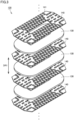
- Fig. 3 is an exploded perspective view showing the configuration of a winding group included in the stationary induction apparatus according to the first embodiment. To facilitate understanding of a structure inside the stationary induction apparatus, a tank is not shown in Fig. 1 .
- a stationary induction apparatus 100 is an on-vehicle transformer.
- Stationary induction apparatus 100 according to the present embodiment is a so-called shell-type transformer.
- Stationary induction apparatus 100 includes a core 110, a winding group 120, and a tank 150.
- core 110 includes a main leg 111 and side legs 112. Side legs 112 are connected to main leg 111.
- winding group 120 includes a plurality of plate windings 130 and a plurality of insulating plates 140.
- Each of the plurality of plate windings 130 is wound around core 110. Specifically, each of the plurality of plate windings 130 is wound around main leg 111 while being passed between main leg 111 and side legs 112. The plurality of plate windings 130 are arranged side by side in an axial direction (DR1 direction) of core 110.
- Each of the plurality of insulating plates 140 is located so as to be sandwiched between plate windings 130 adjacent to each other in the plurality of plate windings 130.
- Each of the plurality of insulating plates 140 provides insulation between plate windings 130 adjacent to each other.
- Each of the plurality of insulating plates 140 is made of an insulating material, for example, an insulating paper such as a pressboard or an insulating material such as polyamide.
- Each of the plurality of insulating plates 140 has a substantially rectangular outer shape as seen in the DR1 direction, and is provided with an opening in its center into which core 110 is inserted.
- the plurality of insulating plates 140 are provided with a plurality of spacers 141.
- Each of the plurality of spacers 141 is made of an insulating material, for example, an insulating paper such as a pressboard or an insulating resin such as polypropylene.
- Each of the plurality of spacers 141 is sandwiched between plate winding 130 and insulating plate 140 facing each other, to form a flow path 10 through which insulating oil (not shown) flows.
- Tank 150 contains core 110, the plurality of plate windings 130, and the plurality of insulating plates 140.
- Tank 150 is filled with the insulating oil.
- Tank 150 is configured to allow the insulating oil to flow in a direction (DR2 direction) orthogonal to the axial direction of core 110 in tank 150.
- Circulation pipes 151 are connected to tank 150. Circulation pipes 151 are connected to opposite ends of tank 150 in the DR2 direction. Circulation pipes 151 are provided with a pump and a cooling container (neither shown). Operation of the pump causes the insulating oil to circulate through tank 150, circulation pipes 151 and the cooling container. The insulating oil is cooled in the cooling container.
- the insulating oil flowing into tank 150 through one of circulation pipes 151 flows in the DR2 direction.
- the insulating oil flows through flow path 10 formed between the plurality of plate windings 130 adjacent to each other. Heat of plate windings 130 adjacent to flow path 10 is thereby transferred to the insulating oil. As a result, the plurality of plate windings 130 are cooled.
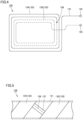
- Fig. 4 is a schematic diagram showing the configuration of the plate winding included in the stationary induction apparatus according to the first embodiment.
- Fig. 5 is a schematic diagram showing the configuration of a portion where insulating coating portions are seamed together in the plate winding according to the first embodiment.
- a conductor portion covered with an insulating coating portion is indicated by a single solid line or dotted line in Fig. 4 .
- each of the plurality of plate windings 130 includes a conductor portion 131 and an insulating coating portion 133.
- Conductor portion 131 is made of copper or aluminum, for example. Conductor portion 131 is wound to have a flat plate shape. Conductor portion 131 is provided with terminals 132 at its opposite ends. Terminals 132 are connected to a conductor portion of an adjacent plate winding, a converter (not shown), or the like.
- Insulating coating portion 133 is spirally wound around conductor portion 131 to cover conductor portion 131. Insulating coating portion 133 provides insulation between adjacent conductor portions 131 of wound conductor portions 131.
- Insulating coating portion 133 is made of an insulating paper such as a pressboard, for example. When an insulating paper is used, insulating coating portion 133 may be formed of a single layer of insulating paper or a plurality of layers of insulating paper.
- a plurality of types of insulating coating portions 133 having different heat resistances from each other are seamed together as insulating coating portion 133 to cover conductor portion 131.
- insulating coating portion 133 of this at least one plate winding 130 in the present embodiment a first insulating coating portion 134 and a second insulating coating portion 135 are seamed together to cover conductor portion 131.
- First insulating coating portion 134 has lower heat resistance than second insulating coating portion 135. Specifically, first insulating coating portion 134 has heat resistance classified into Class A of the JIS standard (JIS C 4003:2010), for example. On the other hand, second insulating coating portion 135 has heat resistance classified into Class B, for example. First insulating coating portion 134 and second insulating coating portion 135 are not limited to have heat resistances classified into Class A or Class B as long as they have different heat resistances from each other.
- each plate winding 130 including the plurality of types of insulating coating portions 133 an insulating coating portion having the lowest heat resistance has the highest arrangement ratio.
- first insulating coating portion 134 having lower heat resistance than second insulating coating portion 135 has the highest arrangement ratio.
- insulating coating portion 133 is formed by the two types of insulating coating portions, that is, first insulating coating portion 134 and second insulating coating portion 135, insulating coating portion 133 is not limited to this formation, and may be formed by three or more types of insulating coating portions. In addition, not all of the plurality of plate windings 130 in winding group 120 are required to have the plurality of types of insulating coating portions 133 having different heat resistances from each other.
- temperature increase due to heat generation caused by application of a voltage varies with location, due to a difference in the amount of magnetic flux transmitted through one plate winding 130 or a difference in the flow rate of a cooling medium.
- temperature tends to increase on the inner side of plate winding 130, and becomes higher than that on the outer side of plate winding 130.
- second insulating coating portion 135 is arranged on the inner side of one plate winding 130 with respect to first insulating coating portion 134.
- insulating coating portion 133 can coat conductor portion 131 with second insulating coating portion 135 having high heat resistance at the location of high temperature, and coat conductor portion 131 with first insulating coating portion 134 having low heat resistance at the location of low temperature.
- the different types of insulating coating portions 133 can be arranged in accordance with the temperature distribution in one plate winding 130.
- second insulating coating portion 135 is arranged on the outer side of one plate winding 130 with respect to first insulating coating portion 134.
- first insulating coating portion 134 and second insulating coating portion 135 are seamed together at a seam portion 136.
- Seam portion 136 in the present embodiment is formed by bonding of first insulating coating portion 134 and second insulating coating portion 135 together with an adhesive tape 137.
- a method for seaming first insulating coating portion 134 and second insulating coating portion 135 together is not limited to the seaming method with adhesive tape 137, as long as first insulating coating portion 134 and second insulating coating portion 135 are connected to each other.
- seam portion 136 is first formed in insulating coating portion 133 by seaming first insulating coating portion 134 and second insulating coating portion 135 together with adhesive tape 137. Seam portion 136 is formed in consideration of a location of plate winding 130 where seam portion 136 is to be arranged.
- insulating coating portion 133 having first insulating coating portion 134 and second insulating coating portion 135 seamed together is spirally wound around conductor portion 131.
- Conductor portion 131 having insulating coating portion 133 wound therearound is formed in a flat plate shape.
- plate winding 130 is formed in which the two types of insulating coating portions 133 having different heat resistances are seamed together to cover conductor portion 131.
- stationary induction apparatus 100 in one plate winding 130, conductor portion 131 is coated with the plurality of types of insulating coating portions 133 corresponding to the respective locations of conductor portion 131. It is thus possible to suppress the amount of use of costly insulating coating portion 133 having high heat resistance, while ensuring heat resistance of plate winding 130. Consequently, stationary induction apparatus 100 with ensured heat resistance of plate winding 130 can be formed at low cost.
- the amount of use of costly insulating coating portion 133 having high heat resistance can be suppressed by setting a ratio of the amount of use of low-cost insulating coating portion 133 having low heat resistance to the highest ratio.
- a stationary induction apparatus according to a second embodiment will be described hereinafter.
- the stationary induction apparatus according to the second embodiment is different from stationary induction apparatus 100 according to the first embodiment only in the configuration of the plate windings. Therefore, description of the remaining configuration will not be repeated.
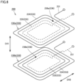
- Fig. 6 is a schematic diagram showing the configuration of a portion where insulating coating portions are seamed together in each of a plurality of plate windings according to the second embodiment.
- a conductor portion covered with an insulating coating portion is indicated by a single solid line or dotted line in Fig. 6 .
- insulating coating portions 233 have a first insulating coating portion 234 and a second insulating coating portion 235.
- each plate winding 230 has a seam portion 236.
- One plate winding 230a is provided with a first seam portion 236a.
- the other plate winding 230b is provided with a second seam portion 236b.
- First seam portion 236a and second seam portion 236b are arranged differently in plate windings 230 as seen in the axial direction (DR1 direction) of the core. Consequently, in plate windings 230a and 230b, the respective arrangements of first insulating coating portion 234 and second insulating coating portion 235 are different from each other.
- each plate winding 230 has a different temperature distribution depending on the position of stacked plate winding 230.
- the respective arrangements of first insulating coating portion 234 and second insulating coating portion 235 in plate windings 230a and 230b can be different from each other. Therefore, costly insulating coating portion 233 having high heat resistance can be used only at a location of high temperature.
- the flow direction of the insulating oil is not limited to the direction orthogonal to the axial direction of the core.
- the insulating oil may flow, for example, along the axial direction (DR1 direction) of the core.
- a plate winding on the downstream side of a flow of the insulating oil increases in temperature due to heat exchange between the insulating oil and the winding group. Therefore, it is desirable to have a higher arrangement ratio of the insulating coating portion having high heat resistance in the downstream plate winding than in a plate winding on the upstream side of the flow of the insulating oil.
- stationary induction apparatus 200 when plate winding 230 has a different temperature distribution depending on the position of stacked plate winding 230, by adjustment of the arrangement of seam portion 236 of insulating coating portion 233 in accordance with each plate winding 230, costly insulating coating portion 233 having high heat resistance can be arranged only at a location of high temperature of each plate winding 230. It is thus possible to suppress the amount of use of costly insulating coating portion 233, while ensuring heat resistance of plate winding 230. Consequently, stationary induction apparatus 200 with ensured heat resistance of plate winding 230 can be formed at low cost.
Landscapes
- Physics & Mathematics (AREA)
- Electromagnetism (AREA)
- Engineering & Computer Science (AREA)
- Power Engineering (AREA)
- Coils Of Transformers For General Uses (AREA)
- Insulating Of Coils (AREA)
Abstract
Description
- The present disclosure relates to a stationary induction apparatus.
-
Japanese Patent Laying-Open No. 09-045551 - PTL 1:
Japanese Patent Laying-Open No. 09-045551 - Generally, in one plate winding of a plurality of plate windings, temperature increase due to heat generation varies with location. A conductor portion of one plate winding is coated with an insulating coating portion having heat resistance corresponding to a location of the highest temperature. This can ensure heat resistance of the winding, but results in excessive use of the costly insulating coating portion having high heat resistance at a location of low temperature of one plate winding.
- The present disclosure was made in view of the problem described above, and has an object to provide a stationary induction apparatus that can suppress the amount of use of a costly insulating coating portion having high heat resistance, while ensuring heat resistance of a winding.
- A stationary induction apparatus based on the present disclosure includes a core and a plurality of plate windings. The plurality of plate windings are arranged side by side in an axial direction of the core, and wound around the core. Each of the plurality of plate windings includes a conductor portion and an insulating coating portion. The insulating coating portion is spirally wound around the conductor portion to cover the conductor portion. In at least one plate winding of the plurality of plate windings, a plurality of types of insulating coating portions having different heat resistances from each other are seamed together as the insulating coating portion to cover the conductor portion.
- According to the present disclosure, in at least one plate winding of a plurality of plate windings, a conductor portion is coated with a plurality of types of insulating coating portions having different heat resistances corresponding to respective locations of the conductor portion. It is thus possible to suppress the amount of use of a costly insulating coating portion having high heat resistance, while ensuring heat resistance of the winding.
-
-
Fig. 1 is a perspective view showing the configuration of a stationary induction apparatus according to a first embodiment. -
Fig. 2 is a cross-sectional view showing the configuration of the stationary induction apparatus according to the first embodiment. -
Fig. 3 is an exploded perspective view showing the configuration of a winding group included in the stationary induction apparatus according to the first embodiment. -
Fig. 4 is a schematic diagram showing the configuration of a plate winding included in the stationary induction apparatus according to the first embodiment. -
Fig. 5 is a schematic diagram showing the configuration of a portion where insulating coating portions are seamed together in the plate winding according to the first embodiment. -
Fig. 6 is a schematic diagram showing the configuration of a portion where insulating coating portions are seamed together in each of a plurality of plate windings according to a second embodiment. - A stationary induction apparatus according to each embodiment will be described hereinafter with reference to the drawings. In the following description of the embodiments, the same or corresponding parts in the drawings are denoted by the same reference characters and description thereof will not be repeated.
-
Fig. 1 is a perspective view showing the configuration of a stationary induction apparatus according to a first embodiment.Fig. 2 is a cross-sectional view showing the configuration of the stationary induction apparatus according to the first embodiment.Fig. 3 is an exploded perspective view showing the configuration of a winding group included in the stationary induction apparatus according to the first embodiment. To facilitate understanding of a structure inside the stationary induction apparatus, a tank is not shown inFig. 1 . - As shown in
Figs. 1 to 3 , astationary induction apparatus 100 according to the first embodiment of the present disclosure is an on-vehicle transformer.Stationary induction apparatus 100 according to the present embodiment is a so-called shell-type transformer.Stationary induction apparatus 100 includes acore 110, awinding group 120, and atank 150. - As shown in
Fig. 1 ,core 110 includes amain leg 111 andside legs 112.Side legs 112 are connected tomain leg 111. - As shown in
Figs. 1 to 3 ,winding group 120 includes a plurality ofplate windings 130 and a plurality ofinsulating plates 140. - Each of the plurality of
plate windings 130 is wound aroundcore 110. Specifically, each of the plurality ofplate windings 130 is wound aroundmain leg 111 while being passed betweenmain leg 111 andside legs 112. The plurality ofplate windings 130 are arranged side by side in an axial direction (DR1 direction) ofcore 110. - Each of the plurality of
insulating plates 140 is located so as to be sandwiched betweenplate windings 130 adjacent to each other in the plurality ofplate windings 130. Each of the plurality ofinsulating plates 140 provides insulation betweenplate windings 130 adjacent to each other. - Each of the plurality of
insulating plates 140 is made of an insulating material, for example, an insulating paper such as a pressboard or an insulating material such as polyamide. Each of the plurality ofinsulating plates 140 has a substantially rectangular outer shape as seen in the DR1 direction, and is provided with an opening in its center into whichcore 110 is inserted. - The plurality of
insulating plates 140 are provided with a plurality ofspacers 141. Each of the plurality ofspacers 141 is made of an insulating material, for example, an insulating paper such as a pressboard or an insulating resin such as polypropylene. Each of the plurality ofspacers 141 is sandwiched between plate winding 130 andinsulating plate 140 facing each other, to form aflow path 10 through which insulating oil (not shown) flows. - Tank 150 contains
core 110, the plurality ofplate windings 130, and the plurality ofinsulating plates 140.Tank 150 is filled with the insulating oil.Tank 150 is configured to allow the insulating oil to flow in a direction (DR2 direction) orthogonal to the axial direction ofcore 110 intank 150. -
Circulation pipes 151 are connected totank 150.Circulation pipes 151 are connected to opposite ends oftank 150 in the DR2 direction.Circulation pipes 151 are provided with a pump and a cooling container (neither shown). Operation of the pump causes the insulating oil to circulate throughtank 150,circulation pipes 151 and the cooling container. The insulating oil is cooled in the cooling container. - The insulating oil flowing into
tank 150 through one ofcirculation pipes 151 flows in the DR2 direction. In windinggroup 120, the insulating oil flows throughflow path 10 formed between the plurality ofplate windings 130 adjacent to each other. Heat ofplate windings 130 adjacent to flowpath 10 is thereby transferred to the insulating oil. As a result, the plurality ofplate windings 130 are cooled. -
Fig. 4 is a schematic diagram showing the configuration of the plate winding included in the stationary induction apparatus according to the first embodiment.Fig. 5 is a schematic diagram showing the configuration of a portion where insulating coating portions are seamed together in the plate winding according to the first embodiment. To facilitate understanding of a structure of the plate winding, a conductor portion covered with an insulating coating portion is indicated by a single solid line or dotted line inFig. 4 . - As shown in
Figs. 4 and 5 , each of the plurality ofplate windings 130 includes aconductor portion 131 and an insulatingcoating portion 133. -
Conductor portion 131 is made of copper or aluminum, for example.Conductor portion 131 is wound to have a flat plate shape.Conductor portion 131 is provided withterminals 132 at its opposite ends.Terminals 132 are connected to a conductor portion of an adjacent plate winding, a converter (not shown), or the like. - Insulating
coating portion 133 is spirally wound aroundconductor portion 131 to coverconductor portion 131. Insulatingcoating portion 133 provides insulation betweenadjacent conductor portions 131 ofwound conductor portions 131. - Insulating
coating portion 133 is made of an insulating paper such as a pressboard, for example. When an insulating paper is used, insulatingcoating portion 133 may be formed of a single layer of insulating paper or a plurality of layers of insulating paper. - In at least one plate winding 130 of the plurality of
plate windings 130, a plurality of types of insulatingcoating portions 133 having different heat resistances from each other are seamed together as insulatingcoating portion 133 to coverconductor portion 131. Specifically, in insulatingcoating portion 133 of this at least one plate winding 130 in the present embodiment, a first insulatingcoating portion 134 and a second insulatingcoating portion 135 are seamed together to coverconductor portion 131. - First insulating
coating portion 134 has lower heat resistance than second insulatingcoating portion 135. Specifically, first insulatingcoating portion 134 has heat resistance classified into Class A of the JIS standard (JIS C 4003:2010), for example. On the other hand, second insulatingcoating portion 135 has heat resistance classified into Class B, for example. First insulatingcoating portion 134 and second insulatingcoating portion 135 are not limited to have heat resistances classified into Class A or Class B as long as they have different heat resistances from each other. - In each plate winding 130 including the plurality of types of insulating
coating portions 133, an insulating coating portion having the lowest heat resistance has the highest arrangement ratio. In plate winding 130 according to the present embodiment, first insulatingcoating portion 134 having lower heat resistance than second insulatingcoating portion 135 has the highest arrangement ratio. - Although insulating
coating portion 133 according to the present embodiment is formed by the two types of insulating coating portions, that is, first insulatingcoating portion 134 and second insulatingcoating portion 135, insulatingcoating portion 133 is not limited to this formation, and may be formed by three or more types of insulating coating portions. In addition, not all of the plurality ofplate windings 130 in windinggroup 120 are required to have the plurality of types of insulatingcoating portions 133 having different heat resistances from each other. - In one plate winding 130, temperature increase due to heat generation caused by application of a voltage varies with location, due to a difference in the amount of magnetic flux transmitted through one plate winding 130 or a difference in the flow rate of a cooling medium. In plate winding 130 according to the present embodiment, for example, temperature tends to increase on the inner side of plate winding 130, and becomes higher than that on the outer side of plate winding 130.
- In this case, second insulating
coating portion 135 is arranged on the inner side of one plate winding 130 with respect to first insulatingcoating portion 134. As a result, in one plate winding 130, insulatingcoating portion 133 cancoat conductor portion 131 with second insulatingcoating portion 135 having high heat resistance at the location of high temperature, andcoat conductor portion 131 with first insulatingcoating portion 134 having low heat resistance at the location of low temperature. In this manner, the different types of insulatingcoating portions 133 can be arranged in accordance with the temperature distribution in one plate winding 130. When the inner side has a lower temperature than the outer side in one plate winding 130, second insulatingcoating portion 135 is arranged on the outer side of one plate winding 130 with respect to first insulatingcoating portion 134. - As shown in
Fig. 5 , first insulatingcoating portion 134 and second insulatingcoating portion 135 are seamed together at aseam portion 136.Seam portion 136 in the present embodiment is formed by bonding of first insulatingcoating portion 134 and second insulatingcoating portion 135 together with anadhesive tape 137. A method for seaming first insulatingcoating portion 134 and second insulatingcoating portion 135 together is not limited to the seaming method withadhesive tape 137, as long as first insulatingcoating portion 134 and second insulatingcoating portion 135 are connected to each other. - In a method for manufacturing this plate winding 130,
seam portion 136 is first formed in insulatingcoating portion 133 by seaming first insulatingcoating portion 134 and second insulatingcoating portion 135 together withadhesive tape 137.Seam portion 136 is formed in consideration of a location of plate winding 130 whereseam portion 136 is to be arranged. - Then, insulating
coating portion 133 having first insulatingcoating portion 134 and second insulatingcoating portion 135 seamed together is spirally wound aroundconductor portion 131.Conductor portion 131 having insulatingcoating portion 133 wound therearound is formed in a flat plate shape. As a result, plate winding 130 is formed in which the two types of insulatingcoating portions 133 having different heat resistances are seamed together to coverconductor portion 131. - In
stationary induction apparatus 100 according to the first embodiment of the present disclosure, in one plate winding 130,conductor portion 131 is coated with the plurality of types of insulatingcoating portions 133 corresponding to the respective locations ofconductor portion 131. It is thus possible to suppress the amount of use of costly insulatingcoating portion 133 having high heat resistance, while ensuring heat resistance of plate winding 130. Consequently,stationary induction apparatus 100 with ensured heat resistance of plate winding 130 can be formed at low cost. - In
stationary induction apparatus 100 according to the first embodiment of the present disclosure, the amount of use of costly insulatingcoating portion 133 having high heat resistance can be suppressed by setting a ratio of the amount of use of low-cost insulatingcoating portion 133 having low heat resistance to the highest ratio. - A stationary induction apparatus according to a second embodiment will be described hereinafter. The stationary induction apparatus according to the second embodiment is different from
stationary induction apparatus 100 according to the first embodiment only in the configuration of the plate windings. Therefore, description of the remaining configuration will not be repeated. -
Fig. 6 is a schematic diagram showing the configuration of a portion where insulating coating portions are seamed together in each of a plurality of plate windings according to the second embodiment. To facilitate understanding of a structure of each plate winding, a conductor portion covered with an insulating coating portion is indicated by a single solid line or dotted line inFig. 6 . - As shown in
Fig. 6 , in astationary induction apparatus 200 according to the second embodiment, in two ormore plate windings 230 of a plurality ofplate windings 230, a plurality of types of insulatingcoating portions 233 are seamed together to cover aconductor portion 231. In each plate winding 230 according to the present embodiment, insulatingcoating portions 233 have a first insulatingcoating portion 234 and a second insulatingcoating portion 235. - In these two or
more plate windings 230, respective arrangements of the plurality of types of insulatingcoating portions 233 inrespective plate windings 230 are different from each other. Specifically, each plate winding 230 has aseam portion 236. One plate winding 230a is provided with afirst seam portion 236a. The other plate winding 230b is provided with asecond seam portion 236b.First seam portion 236a andsecond seam portion 236b are arranged differently inplate windings 230 as seen in the axial direction (DR1 direction) of the core. Consequently, inplate windings coating portion 234 and second insulatingcoating portion 235 are different from each other. - In the present embodiment, each plate winding 230 has a different temperature distribution depending on the position of stacked plate winding 230. By adjustment of the arrangement of
seam portion 236 of insulatingcoating portion 233 in accordance with the temperature distribution in each ofplate windings coating portion 234 and second insulatingcoating portion 235 inplate windings coating portion 233 having high heat resistance can be used only at a location of high temperature. - Although the present embodiment describes the insulating oil as flowing along the direction (DR2 direction) orthogonal to the axial direction of the core, the flow direction of the insulating oil is not limited to the direction orthogonal to the axial direction of the core. The insulating oil may flow, for example, along the axial direction (DR1 direction) of the core. In this case, a plate winding on the downstream side of a flow of the insulating oil increases in temperature due to heat exchange between the insulating oil and the winding group. Therefore, it is desirable to have a higher arrangement ratio of the insulating coating portion having high heat resistance in the downstream plate winding than in a plate winding on the upstream side of the flow of the insulating oil.
- In
stationary induction apparatus 200 according to the second embodiment of the present disclosure, when plate winding 230 has a different temperature distribution depending on the position of stacked plate winding 230, by adjustment of the arrangement ofseam portion 236 of insulatingcoating portion 233 in accordance with each plate winding 230, costly insulatingcoating portion 233 having high heat resistance can be arranged only at a location of high temperature of each plate winding 230. It is thus possible to suppress the amount of use of costly insulatingcoating portion 233, while ensuring heat resistance of plate winding 230. Consequently,stationary induction apparatus 200 with ensured heat resistance of plate winding 230 can be formed at low cost. - It should be understood that the embodiments disclosed herein are illustrative in every respect, and do not serve as a basis for restrictive interpretation. Therefore, the technical scope of the present disclosure is not interpreted based on the foregoing embodiments only, and encompasses all modifications and variations equivalent in meaning and scope to the claims. In the description of the foregoing embodiments, configurations that can be combined with each other may be combined together.
- 10 flow path; 100, 200 stationary induction apparatus; 110 core; 111 main leg; 112 side leg; 120 winding group; 130, 230, 230a, 230b plate winding; 131, 231 conductor portion; 132 terminal; 133, 233 insulating coating portion; 134, 234 first insulating coating portion; 135, 235 second insulating coating portion; 136, 236 seam portion; 137 adhesive tape; 140 insulating plate; 141 spacer; 150 tank; 151 circulation pipe; 236a first seam portion; 236b second seam portion.
Claims (3)
- A stationary induction apparatus comprising:a core; anda plurality of plate windings arranged side by side in an axial direction of the core and wound around the core, whereineach of the plurality of plate windings includes a conductor portion, and an insulating coating portion spirally wound around the conductor portion to cover the conductor portion, andin at least one plate winding of the plurality of plate windings, a plurality of types of insulating coating portions having different heat resistances from each other are seamed together as the insulating coating portion to cover the conductor portion.
- The stationary induction apparatus according to claim 1, wherein in two or more plate windings of the plurality of plate windings, the plurality of types of insulating coating portions are seamed together to cover the conductor portion, and respective arrangements of the plurality of types of insulating coating portions in the respective plate windings are different from each other.
- The stationary induction apparatus according to claim 1 or 2, wherein in each plate winding including the plurality of types of insulating coating portions, an insulating coating portion having lowest heat resistance has a highest arrangement ratio.
Applications Claiming Priority (1)
| Application Number | Priority Date | Filing Date | Title |
|---|---|---|---|
| PCT/JP2022/017258 WO2023195126A1 (en) | 2022-04-07 | 2022-04-07 | Stationary induction apparatus |
Publications (2)
| Publication Number | Publication Date |
|---|---|
| EP4506971A1 true EP4506971A1 (en) | 2025-02-12 |
| EP4506971A4 EP4506971A4 (en) | 2025-06-04 |
Family
ID=84784203
Family Applications (1)
| Application Number | Title | Priority Date | Filing Date |
|---|---|---|---|
| EP22936525.9A Withdrawn EP4506971A4 (en) | 2022-04-07 | 2022-04-07 | FIXED INDUCTION DEVICE |
Country Status (3)
| Country | Link |
|---|---|
| EP (1) | EP4506971A4 (en) |
| JP (1) | JP7199606B1 (en) |
| WO (1) | WO2023195126A1 (en) |
Family Cites Families (9)
| Publication number | Priority date | Publication date | Assignee | Title |
|---|---|---|---|---|
| JPS4918656Y1 (en) * | 1969-03-19 | 1974-05-18 | ||
| JPS5279256A (en) * | 1975-12-25 | 1977-07-04 | Hitachi Ltd | Fabrication method for coil used in electrical machinery and apparatus |
| JPS5678311U (en) * | 1979-11-13 | 1981-06-25 | ||
| JPH0611009B2 (en) * | 1983-09-09 | 1994-02-09 | 株式会社日立製作所 | Resin mold coil |
| JPS6066014U (en) * | 1983-10-14 | 1985-05-10 | 株式会社日立製作所 | Dry transformer winding |
| JPH0917649A (en) * | 1995-06-28 | 1997-01-17 | Hitachi Ltd | Stationary induction device |
| JPH0945551A (en) * | 1995-08-02 | 1997-02-14 | Hitachi Ltd | Gas insulated static induction |
| JP2011159500A (en) * | 2010-02-01 | 2011-08-18 | Japan Ae Power Systems Corp | Insulated wire of winding for insulated oil-filled stationary induction electrical apparatus |
| JP5546051B2 (en) | 2012-03-28 | 2014-07-09 | 株式会社川島織物セルコン | Tile construction jig |
-
2022
- 2022-04-07 JP JP2022548741A patent/JP7199606B1/en active Active
- 2022-04-07 WO PCT/JP2022/017258 patent/WO2023195126A1/en not_active Ceased
- 2022-04-07 EP EP22936525.9A patent/EP4506971A4/en not_active Withdrawn
Also Published As
| Publication number | Publication date |
|---|---|
| WO2023195126A1 (en) | 2023-10-12 |
| JPWO2023195126A1 (en) | 2023-10-12 |
| JP7199606B1 (en) | 2023-01-05 |
| EP4506971A4 (en) | 2025-06-04 |
Similar Documents
| Publication | Publication Date | Title |
|---|---|---|
| EP2406798B1 (en) | An electric transformer with improved cooling system | |
| US8928441B2 (en) | Liquid cooled magnetic component with indirect cooling for high frequency and high power applications | |
| US7012497B2 (en) | Transformer for producing high electrical currents | |
| US8274351B2 (en) | Transformer device | |
| US11393621B2 (en) | Winding wire, coil, and transformer | |
| US20130135072A1 (en) | Reactor and manufacturing method for reactor | |
| JP5522658B2 (en) | Static induction equipment | |
| CN114127871B (en) | Fluid-Cooled Magnetics | |
| CN107077953A (en) | Coil form with low interwinding capacity | |
| EP4506971A1 (en) | Stationary induction apparatus | |
| KR101984464B1 (en) | Transformer and power converter with it | |
| US4489298A (en) | Insulating structure for magnetic coils | |
| US3602858A (en) | Winding with cooling ducts | |
| US7655867B2 (en) | Conductor for liquid-cooled windings | |
| JPH0945551A (en) | Gas insulated static induction | |
| US8344840B2 (en) | Transformer | |
| US12027284B2 (en) | Electrically insulated electric conductor strip, in particular for electric motors and transformers | |
| CN109065335A (en) | Transformer fe core assembly and transformer | |
| EP2618348A2 (en) | Electrical apparatus having a thermally conductive bobbin | |
| EP3961663A1 (en) | Stationary induction device | |
| JP2022152034A (en) | oil-filled transformer | |
| CN114360873A (en) | Dry-type transformer with voltage class of 72.5kV | |
| CN101341556A (en) | Interleaved planar transformer primary and secondary windings | |
| US20180197676A1 (en) | Insulation for tranformer or inductor | |
| JPH06275444A (en) | Gas insulated transformer |
Legal Events
| Date | Code | Title | Description |
|---|---|---|---|
| STAA | Information on the status of an ep patent application or granted ep patent |
Free format text: STATUS: THE INTERNATIONAL PUBLICATION HAS BEEN MADE |
|
| PUAI | Public reference made under article 153(3) epc to a published international application that has entered the european phase |
Free format text: ORIGINAL CODE: 0009012 |
|
| STAA | Information on the status of an ep patent application or granted ep patent |
Free format text: STATUS: REQUEST FOR EXAMINATION WAS MADE |
|
| 17P | Request for examination filed |
Effective date: 20240926 |
|
| AK | Designated contracting states |
Kind code of ref document: A1 Designated state(s): AL AT BE BG CH CY CZ DE DK EE ES FI FR GB GR HR HU IE IS IT LI LT LU LV MC MK MT NL NO PL PT RO RS SE SI SK SM TR |
|
| REG | Reference to a national code |
Ref country code: DE Ref legal event code: R079 Free format text: PREVIOUS MAIN CLASS: H01F0027320000 Ipc: H05B0006100000 |
|
| A4 | Supplementary search report drawn up and despatched |
Effective date: 20250507 |
|
| RIC1 | Information provided on ipc code assigned before grant |
Ipc: H01F 27/12 20060101ALI20250429BHEP Ipc: H01F 27/02 20060101ALI20250429BHEP Ipc: H01F 27/32 20060101ALI20250429BHEP Ipc: H05B 6/36 20060101ALI20250429BHEP Ipc: H05B 6/44 20060101ALI20250429BHEP Ipc: H05B 6/42 20060101ALI20250429BHEP Ipc: H05B 6/10 20060101AFI20250429BHEP |
|
| DAV | Request for validation of the european patent (deleted) | ||
| DAX | Request for extension of the european patent (deleted) | ||
| STAA | Information on the status of an ep patent application or granted ep patent |
Free format text: STATUS: THE APPLICATION HAS BEEN WITHDRAWN |
|
| 18W | Application withdrawn |
Effective date: 20251118 |