EP4506904A1 - Obstacle detection device and obstacle detection method - Google Patents
Obstacle detection device and obstacle detection method Download PDFInfo
- Publication number
- EP4506904A1 EP4506904A1 EP24188862.7A EP24188862A EP4506904A1 EP 4506904 A1 EP4506904 A1 EP 4506904A1 EP 24188862 A EP24188862 A EP 24188862A EP 4506904 A1 EP4506904 A1 EP 4506904A1
- Authority
- EP
- European Patent Office
- Prior art keywords
- image
- camera
- coordinate system
- coordinates
- detection object
- Prior art date
- Legal status (The legal status is an assumption and is not a legal conclusion. Google has not performed a legal analysis and makes no representation as to the accuracy of the status listed.)
- Pending
Links
Images


Classifications
-
- B—PERFORMING OPERATIONS; TRANSPORTING
- B66—HOISTING; LIFTING; HAULING
- B66F—HOISTING, LIFTING, HAULING OR PUSHING, NOT OTHERWISE PROVIDED FOR, e.g. DEVICES WHICH APPLY A LIFTING OR PUSHING FORCE DIRECTLY TO THE SURFACE OF A LOAD
- B66F17/00—Safety devices, e.g. for limiting or indicating lifting force
- B66F17/003—Safety devices, e.g. for limiting or indicating lifting force for fork-lift trucks
-
- G—PHYSICS
- G06—COMPUTING OR CALCULATING; COUNTING
- G06V—IMAGE OR VIDEO RECOGNITION OR UNDERSTANDING
- G06V20/00—Scenes; Scene-specific elements
- G06V20/50—Context or environment of the image
- G06V20/52—Surveillance or monitoring of activities, e.g. for recognising suspicious objects
-
- G—PHYSICS
- G06—COMPUTING OR CALCULATING; COUNTING
- G06T—IMAGE DATA PROCESSING OR GENERATION, IN GENERAL
- G06T7/00—Image analysis
- G06T7/70—Determining position or orientation of objects or cameras
-
- G—PHYSICS
- G01—MEASURING; TESTING
- G01C—MEASURING DISTANCES, LEVELS OR BEARINGS; SURVEYING; NAVIGATION; GYROSCOPIC INSTRUMENTS; PHOTOGRAMMETRY OR VIDEOGRAMMETRY
- G01C21/00—Navigation; Navigational instruments not provided for in groups G01C1/00 - G01C19/00
- G01C21/10—Navigation; Navigational instruments not provided for in groups G01C1/00 - G01C19/00 by using measurements of speed or acceleration
- G01C21/12—Navigation; Navigational instruments not provided for in groups G01C1/00 - G01C19/00 by using measurements of speed or acceleration executed aboard the object being navigated; Dead reckoning
- G01C21/16—Navigation; Navigational instruments not provided for in groups G01C1/00 - G01C19/00 by using measurements of speed or acceleration executed aboard the object being navigated; Dead reckoning by integrating acceleration or speed, i.e. inertial navigation
- G01C21/165—Navigation; Navigational instruments not provided for in groups G01C1/00 - G01C19/00 by using measurements of speed or acceleration executed aboard the object being navigated; Dead reckoning by integrating acceleration or speed, i.e. inertial navigation combined with non-inertial navigation instruments
- G01C21/1656—Navigation; Navigational instruments not provided for in groups G01C1/00 - G01C19/00 by using measurements of speed or acceleration executed aboard the object being navigated; Dead reckoning by integrating acceleration or speed, i.e. inertial navigation combined with non-inertial navigation instruments with passive imaging devices, e.g. cameras
-
- G—PHYSICS
- G01—MEASURING; TESTING
- G01S—RADIO DIRECTION-FINDING; RADIO NAVIGATION; DETERMINING DISTANCE OR VELOCITY BY USE OF RADIO WAVES; LOCATING OR PRESENCE-DETECTING BY USE OF THE REFLECTION OR RERADIATION OF RADIO WAVES; ANALOGOUS ARRANGEMENTS USING OTHER WAVES
- G01S11/00—Systems for determining distance or velocity not using reflection or reradiation
- G01S11/12—Systems for determining distance or velocity not using reflection or reradiation using electromagnetic waves other than radio waves
-
- G—PHYSICS
- G06—COMPUTING OR CALCULATING; COUNTING
- G06T—IMAGE DATA PROCESSING OR GENERATION, IN GENERAL
- G06T3/00—Geometric image transformations in the plane of the image
- G06T3/18—Image warping, e.g. rearranging pixels individually
-
- G—PHYSICS
- G06—COMPUTING OR CALCULATING; COUNTING
- G06T—IMAGE DATA PROCESSING OR GENERATION, IN GENERAL
- G06T5/00—Image enhancement or restoration
- G06T5/80—Geometric correction
-
- G—PHYSICS
- G06—COMPUTING OR CALCULATING; COUNTING
- G06T—IMAGE DATA PROCESSING OR GENERATION, IN GENERAL
- G06T7/00—Image analysis
- G06T7/70—Determining position or orientation of objects or cameras
- G06T7/73—Determining position or orientation of objects or cameras using feature-based methods
-
- G—PHYSICS
- G06—COMPUTING OR CALCULATING; COUNTING
- G06V—IMAGE OR VIDEO RECOGNITION OR UNDERSTANDING
- G06V10/00—Arrangements for image or video recognition or understanding
- G06V10/20—Image preprocessing
- G06V10/22—Image preprocessing by selection of a specific region containing or referencing a pattern; Locating or processing of specific regions to guide the detection or recognition
- G06V10/23—Image preprocessing by selection of a specific region containing or referencing a pattern; Locating or processing of specific regions to guide the detection or recognition based on positionally close patterns or neighbourhood relationships
-
- G—PHYSICS
- G06—COMPUTING OR CALCULATING; COUNTING
- G06V—IMAGE OR VIDEO RECOGNITION OR UNDERSTANDING
- G06V10/00—Arrangements for image or video recognition or understanding
- G06V10/40—Extraction of image or video features
- G06V10/44—Local feature extraction by analysis of parts of the pattern, e.g. by detecting edges, contours, loops, corners, strokes or intersections; Connectivity analysis, e.g. of connected components
-
- G—PHYSICS
- G06—COMPUTING OR CALCULATING; COUNTING
- G06V—IMAGE OR VIDEO RECOGNITION OR UNDERSTANDING
- G06V20/00—Scenes; Scene-specific elements
- G06V20/50—Context or environment of the image
- G06V20/56—Context or environment of the image exterior to a vehicle by using sensors mounted on the vehicle
-
- G—PHYSICS
- G06—COMPUTING OR CALCULATING; COUNTING
- G06V—IMAGE OR VIDEO RECOGNITION OR UNDERSTANDING
- G06V20/00—Scenes; Scene-specific elements
- G06V20/50—Context or environment of the image
- G06V20/56—Context or environment of the image exterior to a vehicle by using sensors mounted on the vehicle
- G06V20/58—Recognition of moving objects or obstacles, e.g. vehicles or pedestrians; Recognition of traffic objects, e.g. traffic signs, traffic lights or roads
-
- G—PHYSICS
- G06—COMPUTING OR CALCULATING; COUNTING
- G06V—IMAGE OR VIDEO RECOGNITION OR UNDERSTANDING
- G06V10/00—Arrangements for image or video recognition or understanding
- G06V10/20—Image preprocessing
- G06V10/24—Aligning, centring, orientation detection or correction of the image
- G06V10/243—Aligning, centring, orientation detection or correction of the image by compensating for image skew or non-uniform image deformations
-
- G—PHYSICS
- G06—COMPUTING OR CALCULATING; COUNTING
- G06V—IMAGE OR VIDEO RECOGNITION OR UNDERSTANDING
- G06V10/00—Arrangements for image or video recognition or understanding
- G06V10/20—Image preprocessing
- G06V10/24—Aligning, centring, orientation detection or correction of the image
- G06V10/247—Aligning, centring, orientation detection or correction of the image by affine transforms, e.g. correction due to perspective effects; Quadrilaterals, e.g. trapezoids
Definitions
- the present invention relates to an obstacle detection device and an obstacle detection method.
- Japanese Patent No. 6940906 discloses a monitoring device that is configured to monitor the surroundings of a working machine.
- the monitoring device includes an image capturing device and a processor.
- the image capturing device captures images of the surroundings of the working machine.
- the processor extracts an image showing the presence of a person from the images captured by the image capturing device.
- the processor measures a distance between the person and the working machine by using the image showing the presence of the person and installation parameters of the image capturing device.
- the processor acquires two dimensional coordinates of the foot (i.e., the foot coordinates) of the person in the captured image.
- the processor measures the distance between the person and the working machine by using the foot coordinates and the installation parameters of the image capturing device.
- the monitoring device disclosed in Japanese Patent No. 6940906 can acquire the distance between the person and the working machine, but cannot acquire the position of the person on the ground.
- the present invention which has been made in light of the above described problem, is directed to providing an obstacle detection device and an obstacle detection method for detecting an actual position of an obstacle in the real world.
- an obstacle detection device includes: a camera attached to an industrial vehicle; and a detector configured to detect an obstacle from a captured image captured by the camera.
- the camera is arranged such that an optical axis of the camera is inclined with respect to a reference plane that is located at a known distance from the camera. A part of the obstacle located on the reference plane serves as a detection object.
- the detector is configured to: estimate coordinates of the detection object in an image coordinate system of the captured image; convert the coordinates of the detection object in the image coordinate system of the captured image into coordinates of the detection object in an image coordinate system of a developed image that is parallel to the reference plane; and calculate a position of the detection object on the reference plane by using the distance from the camera to the reference plane and a relational expression between the coordinates of the detection object in the image coordinate system of the developed image and coordinates of the detection object in a world coordinate system that is a real world coordinate system with the camera centered.
- an obstacle detection method includes detecting an obstacle from a captured image by using a detector.
- the captured image is captured by a camera attached to an industrial vehicle.
- the camera is arranged such that an optical axis of the camera is inclined with respect to a reference plane that is located at a known distance from the camera. A part of the obstacle located on the reference plane serves as a detection object.
- the obstacle detection method includes: estimating coordinates of the detection object in an image coordinate system of the captured image; converting the coordinates of the detection object in the image coordinate system of the captured image into coordinates of the detection object in an image coordinate system of a developed image that is parallel to the reference plane; and calculating a position of the detection object on the reference plane by using the distance from the camera to the reference plane and a relational expression between the coordinates of the detection object in the image coordinate system of the developed image and coordinates of the detection object in a world coordinate system that is a real world coordinate system with the camera centered.
- the obstacle detection device and the obstacle detection method according to the present embodiment are applicable to an industrial vehicle, such as a forklift truck.
- directions such as front, rear, right, left, up, and down, refer to the direction with respect to the forward movement of the forklift truck.
- the right-left direction corresponds to the vehicle width direction of the forklift truck.
- a forklift truck 10 includes a vehicle body 11, and two drive wheels 12.
- the vehicle body 11 includes a head guard 13 and four pillars 14.
- the head guard 13 is supported by the four pillars 14.
- the forklift truck 10 includes a travel motor 15. Driving the travel motor 15 rotates the drive wheels 12, thereby allowing the travel of the forklift truck 10.
- the forklift truck 10 includes a warning device 16.
- the warning device 16 is configured to issue warning if an obstacle is present around the forklift truck 10. Examples of the warning device 16 include a warning buzzer and a warning light.
- the forklift truck 10 includes a controller 17.
- the controller 17 controls the forklift truck 10. Specifically, the controller 17 controls the travel motor 15 to control the travel of the forklift truck 10.
- the controller 17 controls the warning operation of the warning device 16.
- the controller 17 includes a processor 17a and a memory 17b.
- the processor 17a is, for example, a central processing unit (CPU), a graphics processing unit (GPU), or a digital signal processor (DSP).
- the memory 17b includes a random access memory (RAM) and a read only memory (ROM).
- the memory 17b stores a program code or an instruction that causes the processor 17a to execute processing.
- the memory 17b i.e., a non-transitory computer-readable storage medium, includes any media accessible by general or dedicated computers.
- the controller 17 may include a hardware circuit, such as an application specific integrated circuit (ASIC) or a field programmable gate array (FPGA).
- the controller 17, which is a processing circuit may include one or more processors that operate according to computer programs, one or more hardware circuits, such as the ASIC or the FPGA, or a combination thereof.
- the forklift truck 10 has an obstacle detection device 20.
- the obstacle detection device 20 is configured to detect the presence of an obstacle around the forklift truck 10.
- the obstacle is a human, more specifically, a person P, such as a worker.
- the obstacle detection device 20 includes a plurality of cameras 21, a detector 22, and an angle detector 23. The plurality of cameras 21 and the angle detector 23 are connected to the detector 22.
- the cameras 21 are digital cameras. Each of the cameras 21 includes a lens and an imaging element.
- the camera 21 is a monocular camera. In the present embodiment, the camera 21 includes a fish-eye lens. That is, the camera 21 according to the present embodiment is a fish-eye camera.
- the camera 21 creates a captured image If (see FIG. 5 ), which is a fish-eye image showing a distorted image of an object.
- the imaging element is a charge coupled device (CCD) image sensor or a complementary metal oxide semiconductor (CMOS) image sensor, for example.
- CMOS complementary metal oxide semiconductor
- the camera 21 is mounted on the forklift truck 10.
- the cameras 21 are attached to the head guard 13 on opposite sides of the head guard 13 in the vehicle width direction. That is, two cameras 21 are attached to the forklift truck 10.
- Each of the cameras 21 according to the present embodiment captures images viewed from the side of the forklift truck 10. That is, the obstacle detection device 20 according to the present embodiment detects the presence of an obstacle beside the forklift truck 10.
- the camera 21 repeatedly captures an image at a predetermined capturing cycle.
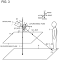
- FIG. 3 illustrates the world coordinate system, which represents a real world coordinate system with the camera 21 centered.
- the world coordinate system is the three-dimensional coordinate system in which the X-axis, the Y-axis, and the Z-axis are perpendicular to each other.
- the X-axis expresses the right-left direction of the forklift truck 10.
- the Y-axis expresses the front-rear direction of the forklift truck 10.
- the Z-axis expresses the up-down direction of the forklift truck 10.
- a road surface R on which the forklift truck 10 travels is expressed by a plane perpendicular to the Z-axis.
- the camera 21 is positioned at a height H from the road surface R.
- the camera 21 is installed at an installation height H from the road surface R.
- the road surface R serves as a reference plane of the present invention that is located at a known distance from the camera 21.
- a part of the obstacle located on the reference plane serves as a detection object of the present invention.
- feet Pf of the person P on the road surface R serves as a part of the obstacle located on the reference plane. That is, according to the present embodiment, the feet Pf serves as the detection object of the present invention.
- the camera 21 is arranged such that the optical axis of the camera 21 is inclined with respect to the reference plane. That is, the camera 21 is arranged such that the optical axis of the camera 21 is inclined with respect to the road surface R.
- the camera 21 is rotated by a pitch angle ⁇ about the Y-axis so that the camera 21 captures a lower view beside the forklift truck 10. That is, the optical axis of the camera 21 is inclined at the pitch angle ⁇ with respect to the Z-axis.
- the pitch angle ⁇ is 30 degrees, for example.
- the camera 21 is not rotated about the X-axis and the Z-axis. That is, the roll angle ⁇ and the yaw angle ⁇ of the camera 21 are zero degrees.
- the detector 22 is configured to detect the obstacle from the captured image If captured by the camera 21.
- the detector 22 includes a processor 22a and a memory 22b.
- the processor 22a include a CPU, a GPU, and a DSP.
- the memory 22b includes a RAM and a ROM.
- the memory 22b stores a program code or an instruction that causes the processor 22a to execute processing.
- the memory 22b i.e., a non-transitory computer-readable storage medium, includes any media accessible by general or dedicated computers.
- the detector 22 may include hardware circuits, such as an ASIC and an FPGA.
- the detector 22, which is a processing circuit may include one or more processors that operate according to computer programs, one or more hardware circuits, such as the ASIC or the FPGA, or a combination thereof.
- the memory 22b stores a machine training model M for machine learning.
- the detector 22 has a machine training model M.
- the machine training model M according to the present embodiment is a model for performing object detection and keypoint detection at the same time. Specifically, the machine training model M receives an image as input, and outputs coordinates of the detection object of the obstacle in the input image as well as outputting and indicating the obstacle in the input image with a bounding box B. According to the present embodiment, the machine training model M receives an image as input, and outputs the coordinates of the feet Pf on the image as input as well as outputting and indicating the person P surrounded by the bounding box B in the input image.
- the machine training model M is produced by machine learning using training data.
- Each of the training data includes a training image of a part of (i.e., the detection object) of the obstacle, the bounding box B surrounding the obstacle in the training image, and the coordinates of the detection object on the training image.
- each of the training data includes a training image of the feet Pf of the person P, the bounding box B surrounding the person P in the training image, and the coordinates of the feet Pf on the training image.
- the training image is the captured image If, which is a fish-eye image. That is, the training image is the captured image If, which is not yet corrected. Distortion correction of the image will be described later.
- the angle detector 23 detects the angle of the camera 21.
- the angle of the camera 21 is defined by the pitch angle ⁇ , the roll angle ⁇ , and the yaw angle ⁇ of the camera 21.
- the angle detector 23 includes an inertial measurement unit (IMU).
- IMU inertial measurement unit
- the obstacle detection device 20 performs the following process, each time the camera 21 captures an image.
- the detector 22 acquires the captured image If from the camera 21 in step S11.
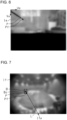
- FIG. 5 shows the captured image If captured by the camera 21.
- the camera 21 according to the present embodiment is a fish-eye camera, and the captured image If is a fish-eye image.
- the person P is present beside the forklift truck 10, the person P is presented in the captured image If.
- the detector 22 estimates the coordinates of the detection object in an image coordinate system of the captured image If in step S12.
- the detector 22 estimates the obstacle in the captured image If and indicates it with the bounding box B at the same time as estimating the coordinates of the detection object in the image coordinate system of the captured image If.
- the detector 22 estimates the person P in the captured image If and indicates it with the bounding box B at the same time as estimating the coordinates of the feet Pf in the image coordinate system of the captured image If.
- FIGS. 3 and 5 illustrate the image coordinate system of the captured image If.
- the top left corner of the captured image If corresponds to the origin of the image coordinate system of the captured image If.
- the image coordinate system of the captured image If is a two-dimensional coordinate system in which the Uf axis and the Vf axis are perpendicular to each other.
- the Uf axis extends along the right-left direction of the captured image If.
- the Vf axis extends along the up-down direction of the captured image If.
- the Uf axis and the Vf axis are perpendicular to the optical axis of the camera 21.
- the detector 22 uses the machine training model M to estimate the person P in the captured image If and indicate the person P with the bounding box B at the same time as estimating the coordinates (Uff, Vff) of the feet Pf in the image coordinate system of the captured image If.
- the machine training model M receives the captured image If as input, of which distortion has not been corrected yet.
- the machine training model M then outputs and indicates the person P in the input captured image If with the bounding box B.
- the machine training model M outputs the coordinates (Uff, Vff) of the feet Pf in the input captured image If.
- step S13 the detector 22 converts the coordinates of the feet Pf in the image coordinate system of the captured image If into the coordinates of the feet Pf in an image coordinate system of a developed image.
- the image coordinate system of the developed image is an image coordinate system of a developed image Ie that is parallel to the reference plane.
- the developed image Ie is a plane perpendicular to the Z-axis.
- the top left corner of the developed image Ie corresponds to the origin of the image coordinate system of the developed image.
- the image coordinate system of the developed image Ie is a two-dimensional coordinate system in which the Ue axis and the Ve axis are perpendicular to each other.
- the Ue axis extends along the right-left direction of the developed image Ie.
- the Ve axis extends along the up-down direction of the developed image Ie.
- the Ue axis and the Ve axis are perpendicular to the Z-axis.
- the developed image Ie is illustrated for the sake of convenience, the developed image Ie is not generated in actual processing because the detector 22 does not convert the captured image If into the developed image Ie.
- the conversion of the captured image If into the developed image Ie is optionally available if it is set in advance that the coordinates in the image coordinate system of the captured image are converted into the coordinates in the image coordinate system of the developed image, which is parallel to the reference plane.
- the detector 22 converts the coordinates (Uff, Vff) of the feet Pf in the image coordinate system of the captured image into the coordinates (Uef, Vef) of the feet Pf in the image coordinate system of the developed image. Specifically, the detector 22 first corrects the distortion of the captured image If. The detector 22 then converts the coordinates (Uff, Vff) of the feet Pf in the image coordinate system of the captured image of which distortion is corrected into the coordinates (Uef, Vef) of the feet Pf in the image coordinate system of the developed image. This conversion of the coordinates uses a rotation matrix RM. The rotation matrix RM is generated based on the angle of the camera 21 detected by the angle detector 23.
- the detector 22 uses the angle of the camera 21 detected by the angle detector 23 to convert the coordinates.
- this conversion of the coordinates uses a camera parameter K expressed by Equation (1).
- K fx 0 cx 0 fy cy 0 0 1
- the distance from the camera 21 to a developed image plane is represented by fx and fy.
- the distance represented by fx and fy may be different from the focal length of the camera 21.
- the center coordinates of the developed image Ie are represented by cx and cy.
- the camera parameter K may be any parameter. For example, the larger the values of fx and fy are, the greater the distance from the camera 21 to the developed image plane.
- the developed image plane has to be parallel to the road surface R, but may be located at an arbitrary distance from the camera 21.
- the detector 22 calculates the position of the detection object on the reference plane in step S14.
- the detector 22 calculates the position of the feet Pf on the road surface R.
- the detector 22 calculates the position of the feet Pf on the road surface R by using the distance from the camera 21 to the road surface R as the reference plane and a relational expression between the coordinates (Uef, Vef) of the feet Pf in the image coordinate system of the developed image and the coordinates (Xf, Yf, Zf) of the feet Pf in the world coordinate system.
- Equation (2) The relational expression between the coordinates (Uef, Vef) of the feet Pf in the image coordinate system of the developed image and the coordinates (Xf, Yf, Zf) of the feet Pf in the world coordinate system is expressed by Equation (2).
- s represents a scale value.
- Equation (3) is obtained by modifying Equation (2).
- the inverse matrix K -1 of the camera parameter K in Equation (3) is expressed by Equation (4). [Math.
- Xf ⁇ H Uef ⁇ cx fx 5
- Yf ⁇ H Vef ⁇ cy fy 6
- the detector 22 detects the position of the feet Pf of the person P in the real world. Furthermore, the detector 22 may calculate the distance from the camera 21 to the feet Pf based on the position of the feet Pf in the real world.
- the controller 17 controls the forklift truck 10 based on the results detected by the detector 22.
- the controller 17 of the present embodiment controls the forklift truck 10 based on the position of the person P in the real world detected by the detector 22.
- the control of the forklift truck 10 by the controller 17 differs depending on whether the person P is on the travel path of the forklift truck 10. For example, when the person P is not on the travel path of the forklift truck 10, the controller 17 lowers the warning level issued by the warning device 16 compared to when the person P is on the travel path of the forklift truck 10. For example, when the person P is on the travel path of the forklift truck 10, the controller 17 controls the travel motor 15 to decelerate the forklift truck 10 or prevent the forklift truck 10 from starting.
- the detector 22 may estimate the coordinates of the intersection of the bounding box B and a line L passing through an arbitrary point Ifp on the captured image If and the center Bc of the bounding box B as the coordinates of the feet Pf in the image coordinate system of the captured image.
- the arbitrary point Ifp on the captured image If is a point located in the center of the bottom edge of the captured image If.
- the arbitrary point Ifp on the captured image If may be changed appropriately depending on the angle of the camera 21.
- the machine training model M does not need to be trained to output the coordinates of the feet Pf in the image coordinate system of the captured image as long as the machine training model M is trained to output and indicate the person P in the input captured image If with the bounding box B.
- This is effective when the machine training model M is already trained to output and indicate the person P in the captured image If with the bounding box B or when there is no training data for training the machine training model M to output the coordinates of the feet Pf in the image coordinate system of the captured image.
- the coordinates of the feet Pf on the captured image If may be output based on the pixels of the imaging element of the camera 21.
- the industrial vehicle is not limited to the forklift truck 10.
- the industrial vehicle may be any industrial vehicle, such as a towing tractor.
- An obstacle detection device comprising:
Landscapes
- Engineering & Computer Science (AREA)
- Physics & Mathematics (AREA)
- General Physics & Mathematics (AREA)
- Theoretical Computer Science (AREA)
- Multimedia (AREA)
- Radar, Positioning & Navigation (AREA)
- Remote Sensing (AREA)
- Computer Vision & Pattern Recognition (AREA)
- Life Sciences & Earth Sciences (AREA)
- Geology (AREA)
- Mechanical Engineering (AREA)
- Structural Engineering (AREA)
- Electromagnetism (AREA)
- Automation & Control Theory (AREA)
- Image Processing (AREA)
- Closed-Circuit Television Systems (AREA)
- Length Measuring Devices By Optical Means (AREA)
- Geophysics And Detection Of Objects (AREA)
- Optical Radar Systems And Details Thereof (AREA)
- Image Analysis (AREA)
Abstract
An obstacle detection device (20) includes: a camera (21); and a detector (22) for detecting an obstacle (P). A part of the obstacle (P) located on the reference plane (R) serves as a detection object (Pf). The detector (22) is configured to: estimate coordinates (Uff, Vff) of the detection object (Pf) in an image coordinate system of a captured image (If); convert the coordinates (Uff, Vff) of the detection object (Pf) in the image coordinate system of the captured image (If) into coordinates (Uef, Vef) of the detection object (Pf) in an image coordinate system of a developed image (le) that is parallel to the reference plane (R); and calculate a position of the detection object (Pf) on the reference plane (R) by using the distance from the camera (21) to the reference plane (R) and a relational expression between the coordinates (Uef, Vef) in the image coordinate system of the developed image (le) and coordinates (Xf, Yf, Zf) of the detection object (Pf) in a world coordinate system with the camera (21) centered.
Description
- The present invention relates to an obstacle detection device and an obstacle detection method.
-
Japanese Patent No. 6940906 - The monitoring device disclosed in
Japanese Patent No. 6940906 - The present invention, which has been made in light of the above described problem, is directed to providing an obstacle detection device and an obstacle detection method for detecting an actual position of an obstacle in the real world.
- In accordance with an aspect of the present invention, there is provided an obstacle detection device. The obstacle detection device includes: a camera attached to an industrial vehicle; and a detector configured to detect an obstacle from a captured image captured by the camera. The camera is arranged such that an optical axis of the camera is inclined with respect to a reference plane that is located at a known distance from the camera. A part of the obstacle located on the reference plane serves as a detection object. The detector is configured to: estimate coordinates of the detection object in an image coordinate system of the captured image; convert the coordinates of the detection object in the image coordinate system of the captured image into coordinates of the detection object in an image coordinate system of a developed image that is parallel to the reference plane; and calculate a position of the detection object on the reference plane by using the distance from the camera to the reference plane and a relational expression between the coordinates of the detection object in the image coordinate system of the developed image and coordinates of the detection object in a world coordinate system that is a real world coordinate system with the camera centered.
- In accordance with another aspect of the present invention, there is provided an obstacle detection method. The obstacle detection method includes detecting an obstacle from a captured image by using a detector. The captured image is captured by a camera attached to an industrial vehicle. The camera is arranged such that an optical axis of the camera is inclined with respect to a reference plane that is located at a known distance from the camera. A part of the obstacle located on the reference plane serves as a detection object. The obstacle detection method includes: estimating coordinates of the detection object in an image coordinate system of the captured image; converting the coordinates of the detection object in the image coordinate system of the captured image into coordinates of the detection object in an image coordinate system of a developed image that is parallel to the reference plane; and calculating a position of the detection object on the reference plane by using the distance from the camera to the reference plane and a relational expression between the coordinates of the detection object in the image coordinate system of the developed image and coordinates of the detection object in a world coordinate system that is a real world coordinate system with the camera centered.
- Other aspects and advantages of the invention will become apparent from the following description, taken in conjunction with the accompanying drawings, illustrating by way of example the principles of the invention.
- The invention, together with objects and advantages thereof, may best be understood by reference to the following description of the embodiments together with the accompanying drawings in which:
-
FIG. 1 is a plan view of a forklift truck; -
FIG. 2 is a block diagram of the forklift truck; -
FIG. 3 is a schematic diagram for explaining an image coordinate system of a captured image, an image coordinate system of a developed image, and a world coordinate system; -
FIG. 4 is a flowchart of an obstacle detection method; -
FIG. 5 shows a captured image; -
FIG. 6 shows a developed image; and -
FIG. 7 shows a captured image for explaining an estimation of foot coordinates according to a modification example. - The following will describe an obstacle detection device and an obstacle detection method according to an embodiment of the present invention with reference to
FIGS 1 to 6 . The obstacle detection device and the obstacle detection method according to the present embodiment are applicable to an industrial vehicle, such as a forklift truck. In the following description, directions, such as front, rear, right, left, up, and down, refer to the direction with respect to the forward movement of the forklift truck. The right-left direction corresponds to the vehicle width direction of the forklift truck. - As illustrated in
FIG. 1 , aforklift truck 10 includes avehicle body 11, and twodrive wheels 12. Thevehicle body 11 includes ahead guard 13 and fourpillars 14. Thehead guard 13 is supported by the fourpillars 14. - As illustrated in
FIG. 2 , theforklift truck 10 includes atravel motor 15. Driving thetravel motor 15 rotates thedrive wheels 12, thereby allowing the travel of theforklift truck 10. Theforklift truck 10 includes awarning device 16. Thewarning device 16 is configured to issue warning if an obstacle is present around theforklift truck 10. Examples of thewarning device 16 include a warning buzzer and a warning light. Theforklift truck 10 includes acontroller 17. Thecontroller 17 controls theforklift truck 10. Specifically, thecontroller 17 controls thetravel motor 15 to control the travel of theforklift truck 10. Thecontroller 17 controls the warning operation of thewarning device 16. - The
controller 17 includes aprocessor 17a and amemory 17b. Theprocessor 17a is, for example, a central processing unit (CPU), a graphics processing unit (GPU), or a digital signal processor (DSP). Thememory 17b includes a random access memory (RAM) and a read only memory (ROM). Thememory 17b stores a program code or an instruction that causes theprocessor 17a to execute processing. Thememory 17b, i.e., a non-transitory computer-readable storage medium, includes any media accessible by general or dedicated computers. Thecontroller 17 may include a hardware circuit, such as an application specific integrated circuit (ASIC) or a field programmable gate array (FPGA). Thecontroller 17, which is a processing circuit, may include one or more processors that operate according to computer programs, one or more hardware circuits, such as the ASIC or the FPGA, or a combination thereof. - The
forklift truck 10 has anobstacle detection device 20. Theobstacle detection device 20 is configured to detect the presence of an obstacle around theforklift truck 10. In the present embodiment, the obstacle is a human, more specifically, a person P, such as a worker. Theobstacle detection device 20 includes a plurality ofcameras 21, adetector 22, and anangle detector 23. The plurality ofcameras 21 and theangle detector 23 are connected to thedetector 22. - The
cameras 21 are digital cameras. Each of thecameras 21 includes a lens and an imaging element. Thecamera 21 is a monocular camera. In the present embodiment, thecamera 21 includes a fish-eye lens. That is, thecamera 21 according to the present embodiment is a fish-eye camera. Thecamera 21 creates a captured image If (seeFIG. 5 ), which is a fish-eye image showing a distorted image of an object. The imaging element is a charge coupled device (CCD) image sensor or a complementary metal oxide semiconductor (CMOS) image sensor, for example. The imaging element consists of pixels. - As illustrated in
FIG. 1 , thecamera 21 is mounted on theforklift truck 10. In the present embodiment, thecameras 21 are attached to thehead guard 13 on opposite sides of thehead guard 13 in the vehicle width direction. That is, twocameras 21 are attached to theforklift truck 10. Each of thecameras 21 according to the present embodiment captures images viewed from the side of theforklift truck 10. That is, theobstacle detection device 20 according to the present embodiment detects the presence of an obstacle beside theforklift truck 10. Thecamera 21 repeatedly captures an image at a predetermined capturing cycle. -
FIG. 3 illustrates the world coordinate system, which represents a real world coordinate system with thecamera 21 centered. The world coordinate system is the three-dimensional coordinate system in which the X-axis, the Y-axis, and the Z-axis are perpendicular to each other. In the present embodiment, the X-axis expresses the right-left direction of theforklift truck 10. The Y-axis expresses the front-rear direction of theforklift truck 10. The Z-axis expresses the up-down direction of theforklift truck 10. A road surface R on which theforklift truck 10 travels is expressed by a plane perpendicular to the Z-axis. - In the present embodiment, the
camera 21 is positioned at a height H from the road surface R. In other words, thecamera 21 is installed at an installation height H from the road surface R. Accordingly, the road surface R serves as a reference plane of the present invention that is located at a known distance from thecamera 21. A part of the obstacle located on the reference plane serves as a detection object of the present invention. According to the present embodiment, feet Pf of the person P on the road surface R serves as a part of the obstacle located on the reference plane. That is, according to the present embodiment, the feet Pf serves as the detection object of the present invention. - The
camera 21 is arranged such that the optical axis of thecamera 21 is inclined with respect to the reference plane. That is, thecamera 21 is arranged such that the optical axis of thecamera 21 is inclined with respect to the road surface R. According to the present embodiment, thecamera 21 is rotated by a pitch angle θ about the Y-axis so that thecamera 21 captures a lower view beside theforklift truck 10. That is, the optical axis of thecamera 21 is inclined at the pitch angle θ with respect to the Z-axis. The pitch angle θ is 30 degrees, for example. According to the present embodiment, thecamera 21 is not rotated about the X-axis and the Z-axis. That is, the roll angle ϕ and the yaw angle ψ of thecamera 21 are zero degrees. - The
detector 22 is configured to detect the obstacle from the captured image If captured by thecamera 21. - As illustrated in
FIG. 2 , thedetector 22 includes aprocessor 22a and amemory 22b. Examples of theprocessor 22a include a CPU, a GPU, and a DSP. Thememory 22b includes a RAM and a ROM. Thememory 22b stores a program code or an instruction that causes theprocessor 22a to execute processing. Thememory 22b, i.e., a non-transitory computer-readable storage medium, includes any media accessible by general or dedicated computers. Thedetector 22 may include hardware circuits, such as an ASIC and an FPGA. Thedetector 22, which is a processing circuit, may include one or more processors that operate according to computer programs, one or more hardware circuits, such as the ASIC or the FPGA, or a combination thereof. - The
memory 22b stores a machine training model M for machine learning. In other words, thedetector 22 has a machine training model M. The machine training model M according to the present embodiment is a model for performing object detection and keypoint detection at the same time. Specifically, the machine training model M receives an image as input, and outputs coordinates of the detection object of the obstacle in the input image as well as outputting and indicating the obstacle in the input image with a bounding box B. According to the present embodiment, the machine training model M receives an image as input, and outputs the coordinates of the feet Pf on the image as input as well as outputting and indicating the person P surrounded by the bounding box B in the input image. - The machine training model M is produced by machine learning using training data. Each of the training data includes a training image of a part of (i.e., the detection object) of the obstacle, the bounding box B surrounding the obstacle in the training image, and the coordinates of the detection object on the training image. According to the present embodiment, each of the training data includes a training image of the feet Pf of the person P, the bounding box B surrounding the person P in the training image, and the coordinates of the feet Pf on the training image. The training image is the captured image If, which is a fish-eye image. That is, the training image is the captured image If, which is not yet corrected. Distortion correction of the image will be described later.
- The
angle detector 23 detects the angle of thecamera 21. The angle of thecamera 21 is defined by the pitch angle θ, the roll angle ψ, and the yaw angle ψ of thecamera 21. Theangle detector 23 includes an inertial measurement unit (IMU). - The following will describe the obstacle detection method and an obstacle detection process performed by the
obstacle detection device 20. Theobstacle detection device 20 according to the present embodiment performs the following process, each time thecamera 21 captures an image. - As illustrated in
FIG. 4 , thedetector 22 acquires the captured image If from thecamera 21 in step S11. -
FIG. 5 shows the captured image If captured by thecamera 21. As previously described, thecamera 21 according to the present embodiment is a fish-eye camera, and the captured image If is a fish-eye image. As illustrated inFIG. 1 , if the person P is present beside theforklift truck 10, the person P is presented in the captured image If. - As illustrated in
FIG. 4 , thedetector 22 estimates the coordinates of the detection object in an image coordinate system of the captured image If in step S12. Thedetector 22 according to the present embodiment estimates the obstacle in the captured image If and indicates it with the bounding box B at the same time as estimating the coordinates of the detection object in the image coordinate system of the captured image If. In other words, thedetector 22 estimates the person P in the captured image If and indicates it with the bounding box B at the same time as estimating the coordinates of the feet Pf in the image coordinate system of the captured image If. -
FIGS. 3 and5 illustrate the image coordinate system of the captured image If. The top left corner of the captured image If corresponds to the origin of the image coordinate system of the captured image If. The image coordinate system of the captured image If is a two-dimensional coordinate system in which the Uf axis and the Vf axis are perpendicular to each other. The Uf axis extends along the right-left direction of the captured image If. The Vf axis extends along the up-down direction of the captured image If. The Uf axis and the Vf axis are perpendicular to the optical axis of thecamera 21. - According to the present embodiment, the
detector 22 uses the machine training model M to estimate the person P in the captured image If and indicate the person P with the bounding box B at the same time as estimating the coordinates (Uff, Vff) of the feet Pf in the image coordinate system of the captured image If. Specifically, the machine training model M receives the captured image If as input, of which distortion has not been corrected yet. The machine training model M then outputs and indicates the person P in the input captured image If with the bounding box B. In addition, the machine training model M outputs the coordinates (Uff, Vff) of the feet Pf in the input captured image If. - As illustrated in
FIG. 4 , in step S13, thedetector 22 converts the coordinates of the feet Pf in the image coordinate system of the captured image If into the coordinates of the feet Pf in an image coordinate system of a developed image. - As illustrated in
FIGS. 3 and6 , the image coordinate system of the developed image is an image coordinate system of a developed image Ie that is parallel to the reference plane. The developed image Ie is a plane perpendicular to the Z-axis. The top left corner of the developed image Ie corresponds to the origin of the image coordinate system of the developed image. The image coordinate system of the developed image Ie is a two-dimensional coordinate system in which the Ue axis and the Ve axis are perpendicular to each other. The Ue axis extends along the right-left direction of the developed image Ie. The Ve axis extends along the up-down direction of the developed image Ie. The Ue axis and the Ve axis are perpendicular to the Z-axis. - Although the developed image Ie is illustrated for the sake of convenience, the developed image Ie is not generated in actual processing because the
detector 22 does not convert the captured image If into the developed image Ie. The conversion of the captured image If into the developed image Ie is optionally available if it is set in advance that the coordinates in the image coordinate system of the captured image are converted into the coordinates in the image coordinate system of the developed image, which is parallel to the reference plane. - The
detector 22 converts the coordinates (Uff, Vff) of the feet Pf in the image coordinate system of the captured image into the coordinates (Uef, Vef) of the feet Pf in the image coordinate system of the developed image. Specifically, thedetector 22 first corrects the distortion of the captured image If. Thedetector 22 then converts the coordinates (Uff, Vff) of the feet Pf in the image coordinate system of the captured image of which distortion is corrected into the coordinates (Uef, Vef) of the feet Pf in the image coordinate system of the developed image. This conversion of the coordinates uses a rotation matrix RM. The rotation matrix RM is generated based on the angle of thecamera 21 detected by theangle detector 23. That is, thedetector 22 uses the angle of thecamera 21 detected by theangle detector 23 to convert the coordinates. In addition, this conversion of the coordinates uses a camera parameter K expressed by Equation (1).
[Math. 1]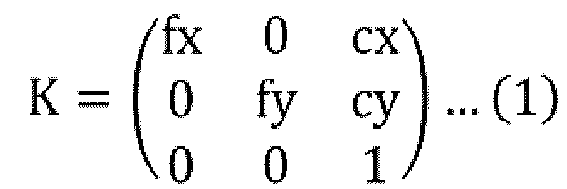
- The distance from the
camera 21 to a developed image plane is represented by fx and fy. The distance represented by fx and fy may be different from the focal length of thecamera 21. The center coordinates of the developed image Ie are represented by cx and cy. The camera parameter K may be any parameter. For example, the larger the values of fx and fy are, the greater the distance from thecamera 21 to the developed image plane. In other words, the developed image plane has to be parallel to the road surface R, but may be located at an arbitrary distance from thecamera 21. - As illustrated in
FIG. 4 , thedetector 22 calculates the position of the detection object on the reference plane in step S14. In the present embodiment, thedetector 22 calculates the position of the feet Pf on the road surface R. Thedetector 22 calculates the position of the feet Pf on the road surface R by using the distance from thecamera 21 to the road surface R as the reference plane and a relational expression between the coordinates (Uef, Vef) of the feet Pf in the image coordinate system of the developed image and the coordinates (Xf, Yf, Zf) of the feet Pf in the world coordinate system. - The relational expression between the coordinates (Uef, Vef) of the feet Pf in the image coordinate system of the developed image and the coordinates (Xf, Yf, Zf) of the feet Pf in the world coordinate system is expressed by Equation (2). In Equation (2), s represents a scale value. Equation (3) is obtained by modifying Equation (2). The inverse matrix K-1 of the camera parameter K in Equation (3) is expressed by Equation (4).
[Math. 2]
- The distance from the
camera 21 to the road surface R corresponds to the installation height H of thecamera 21 from the road surface R. Accordingly, it can be assumed that Zf = -H. The coordinate Zf is equal to s (Zf = s). Accordingly, s is equal to -H (s = -H). Because of Equation (3) and s = -H, the position of the feet Pf on the road surface R is calculated as expressed by Equation (5) and Equation (6).
- In such a way, the
detector 22 detects the position of the feet Pf of the person P in the real world. Furthermore, thedetector 22 may calculate the distance from thecamera 21 to the feet Pf based on the position of the feet Pf in the real world. - The
controller 17 controls theforklift truck 10 based on the results detected by thedetector 22. Thecontroller 17 of the present embodiment controls theforklift truck 10 based on the position of the person P in the real world detected by thedetector 22. Specifically, the control of theforklift truck 10 by thecontroller 17 differs depending on whether the person P is on the travel path of theforklift truck 10. For example, when the person P is not on the travel path of theforklift truck 10, thecontroller 17 lowers the warning level issued by thewarning device 16 compared to when the person P is on the travel path of theforklift truck 10. For example, when the person P is on the travel path of theforklift truck 10, thecontroller 17 controls thetravel motor 15 to decelerate theforklift truck 10 or prevent theforklift truck 10 from starting. - The following will describe the operations and the advantageous effects of the present embodiment.
- (1) The
camera 21 is arranged such that the optical axis of thecamera 21 is inclined with respect to the road surface R that is located at a known distance from thecamera 21. The feet Pf of the person P is positioned on the road surface R. Thedetector 22 estimates the coordinates of the feet Pf in the image coordinate system of the captured image If. Thedetector 22 converts the coordinates of the feet Pf in the image coordinate system of the captured image If into the coordinates of the feet Pf in the image coordinate system of the developed image Ie, which is parallel to the road surface R. Thedetector 22 calculates the position of the feet Pf on the road surface R by using the distance from thecamera 21 to the road surface R and the relational expression between the coordinates of the feet Pf in the image coordinate system of the developed image and the coordinates of the feet Pf in the world coordinate system, which is a real world coordinate system with thecamera 21 centered.
This allows thedetector 22 to convert the coordinates of the feet Pf in the image coordinate system of the captured image into the coordinates of the feet Pf in the image coordinate system of the developed view image. The distance from thecamera 21 to the road surface R is known. This allows thedetector 22 to calculate the position of the feet Pf on the road surface R by using the relational expression between the coordinates of the feet Pf in the image coordinate system of the developed image and the coordinates of the feet Pf in the world coordinate system. This therefore allows thedetector 22 to detect the position of the person P in the real world. - (2) The
detector 22 converts the coordinates of the feet Pf in the image coordinate system of the captured image into the coordinates of the feet Pf in the image coordinate system of the developed image by using the roll angle ϕ and the yaw angle ψ of thecamera 21 as well as the pitch angle θ of thecamera 21. This allows thedetector 22 to take into consideration not only the pitch angle θ of thecamera 21 but also the roll angle ϕ and the yaw angle ψ of thecamera 21 to detect the position of the person P in the real world. This therefore increases the degree of freedom in the mounting posture of thecamera 21. - (3) The
cameras 21 are fish-eye cameras. This increases the angle of view of eachcamera 21, thereby allowing an increase in detection range of the person P. Furthermore, thedetector 22 corrects distortion of the captured image If when converting the coordinates of the feet Pf in the image coordinate system of the captured image into the coordinates of the feet Pf in the image coordinate system of the developed image. This facilitates detection of the position of person P in the real world. - (4) When the captured image If is converted into the developed image Ie, the angle of view is limited. Accordingly, the developed image Ie may not show the whole of the person P depending on the position of the person P in the captured image If. Furthermore, as shown in
FIG. 6 , the person P is shown distorted in the developed image Ie. In the present embodiment, the training image and the image as input received by the machine training model M are the captured image If before distortion of which is corrected. This allows the machine training model M to be more effectively generated and increases the estimation accuracy of the coordinates of the feet Pf compared to a case where the training image and the image as input received by the machine training model M are the developed image Ie. - (5) The angle of the
camera 21 may change. For example, theforklift truck 10 may tilt to the right or left when theforklift truck 10 turns, and the pitch angle θ therefore may change. Furthermore, theforklift truck 10 may tilt forward or backward when theforklift truck 10 carries a load or travels on a slope, and the roll angle ϕ therefore may change. Theobstacle detection device 20 according to the present embodiment includes theangle detector 23 that is configured to detect the angle of thecamera 21. Thedetector 22 uses the angle of thecamera 21 detected by theangle detector 23 to convert the coordinates of the feet Pf. This suppresses a decrease in the accuracy of detection of the position of the person P in the real world even if the angle of thecamera 21 changes. - (6) In the present embodiment, the obstacle is the person P. The detection object is the feet Pf of the person P. The reference plane is the road surface R. The installation height H of the
camera 21 from the road surface R corresponds to the distance from thecamera 21 to the reference plane. This allows the distance from thecamera 21 to the reference plane to be easily and correctly known. In addition, the feet Pf of the person P are in contact with the road surface R and are therefore suitable as the detection object for detection. This therefore increases the accuracy of detection of the position of the person P. - (7) The
obstacle detection device 20 detects the position of the person P in the real world. This allows thecontroller 17 to control the travel of theforklift truck 10 and the warning operation of thewarning device 16 more precisely, compared to a case where theobstacle detection device 20, for example, only detects the distance from theforklift truck 10 to the person P. - (8) The
camera 21 is a monocular camera. This reduces the cost of detection of the person P, compared to a case where an expensive camera, such as a stereo camera, is used for the detection of the person P. - The above embodiment may be modified and implemented as follows. The embodiment and the following modified examples may be implemented in combination with each other within a technically consistent range.
- ∘ The obstacle detected by the
obstacle detection device 20 and the obstacle detection method is not limited to the person P, and may be an object other than a human. - ∘ The
cameras 21 are not limited to fish-eye cameras. Each of thecameras 21 may be a wide-angle camera, or may be a camera with a narrower angle of view than an angle of view of a fish-eye camera and a wide-angle camera. - ∘ The number of the
cameras 21 attached to theforklift truck 10 is not limited to two and may be changed as appropriate. - ∘ The
cameras 21 are attached to thehead guard 13 of theforklift truck 10 in the present embodiment, but is not limited thereto. Thecameras 21 may be attached to any component as appropriate depending on a detection range of an obstacle required. - ∘ The
cameras 21 may capture images of a view in front of or behind theforklift truck 10. In this case, theobstacle detection device 20 detects an obstacle present in front of or behind theforklift truck 10. - ∘ In the above embodiment, for the sake of convenience, each of the
cameras 21 is rotated only about the Y-axis, but may be rotated about the X-axis or the Z-axis. - ∘ In the above embodiment, the
detector 22 estimates the person P in the captured image If and indicates it with the bounding box B at the same time as estimating the coordinates of the feet Pf in the image coordinate system of the captured image If. However, thedetector 22 may estimate only the coordinates of the feet Pf in the image coordinate system of the captured image If without estimating the person P in the captured image If and indicating it with the bounding box B. In this case, the machine training model M does not need to be trained for object detection as long as the machine training model M is trained for keypoint detection. - ∘ The reference plane is not limited to the road surface R. For example, the distance from
camera 21 to the head of the person P standing on the road surface R may be known by subtracting the height of the person P from the installation height H of thecamera 21 from the road surface R. Accordingly, the reference plane may be a plane positioned at the height of the person P from the road surface R. In this case, the head of the person P or a helmet on the head of the person P serves as the detection object. - ∘ In the above embodiment, the
detector 22 estimates the coordinates of the feet Pf in the image coordinate system of the captured image by performing keypoint detection. However, thedetector 22 may estimate the coordinates of the feet Pf in the image coordinate system of the captured image by performing object detection. - As shown in
FIG. 7 , thedetector 22 may estimate the coordinates of the intersection of the bounding box B and a line L passing through an arbitrary point Ifp on the captured image If and the center Bc of the bounding box B as the coordinates of the feet Pf in the image coordinate system of the captured image. In the example shown inFIG. 7 , the arbitrary point Ifp on the captured image If is a point located in the center of the bottom edge of the captured image If. The arbitrary point Ifp on the captured image If may be changed appropriately depending on the angle of thecamera 21. - In such a case where the coordinates of the intersection of the bounding box B and the line L are estimated as the coordinates of the feet Pf, the machine training model M does not need to be trained to output the coordinates of the feet Pf in the image coordinate system of the captured image as long as the machine training model M is trained to output and indicate the person P in the input captured image If with the bounding box B. This is effective when the machine training model M is already trained to output and indicate the person P in the captured image If with the bounding box B or when there is no training data for training the machine training model M to output the coordinates of the feet Pf in the image coordinate system of the captured image. The coordinates of the feet Pf on the captured image If may be output based on the pixels of the imaging element of the
camera 21. - ∘ If the angle of the
camera 21 is expected to remain almost unchanged, theobstacle detection device 20 does not need to include theangle detector 23. In this configuration, thedetector 22 uses the angle of the camera 21 (i.e., the angle of the camera detected by the angle detector 23) stored in advance to convert the coordinates of the feet Pf in the image coordinate system of the captured image into the coordinates of the feet Pf in the image coordinate system of the developed image. - The industrial vehicle is not limited to the
forklift truck 10. The industrial vehicle may be any industrial vehicle, such as a towing tractor. - The following will describe technical ideas that can be understood from the above embodiment and the modification examples.
- An obstacle detection device comprising:
- a camera attached to an industrial vehicle; and
- a detector configured to detect an obstacle from a captured image captured by the camera, wherein
- the camera is arranged such that an optical axis of the camera is inclined with respect to a reference plane that is located at a known distance from the camera,
- a part of the obstacle located on the reference plane serves as a detection object, and
- the detector is configured to:
- estimate coordinates of the detection object in an image coordinate system of the captured image;
- convert the coordinates of the detection object in the image coordinate system of the captured image into coordinates of the detection object in an image coordinate system of a developed image, the developed image being parallel to the reference plane; and
- calculate a position of the detection object on the reference plane by using the distance from the camera to the reference plane and a relational expression between the coordinates of the detection object in the image coordinate system of the developed image and coordinates of the detection object in a world coordinate system, the world coordinate system being a real world coordinate system with the camera centered.
- The obstacle detection device according to Note 1, wherein
- the camera is a fish-eye camera or a wide-angle camera, and
- the detector corrects distortion of the captured image when converting the coordinates of the detection object in the image coordinate system of the captured image into the coordinates of the detection object in the image coordinate system of the developed image.
- The obstacle detection device according to Note 2, wherein
- the detector has a machine training model produced by machine learning using training data, the training data including a training image of the detection object and coordinates of the detection object on the training image, the machine training model receiving an image as input and outputting coordinates of the detection object on the image as input, and
- the training image and the image as input received by the machine training model are the captured image before the distortion of the captured image is corrected.
- The obstacle detection device according to any one of Notes 1 to 3, wherein
- the obstacle detection device includes an angle detector configured to detect an angle of the camera, and
- the detector uses the angle of the camera detected by the angle detector to convert the coordinates of the detection object in the image coordinate system of the captured image into the coordinates of the detection object in the image coordinate system of the developed image.
- The obstacle detection device according to any one of Notes 1 to 4, wherein
- the obstacle is a human,
- the detection object is feet of the human, and
- the reference plane is a road surface.
Claims (6)
- An obstacle detection device (20) comprising:a camera (21) attached to an industrial vehicle (10); anda detector (22) configured to detect an obstacle (P) from a captured image (If) captured by the camera (21), characterized in thatthe camera (21) is arranged such that an optical axis of the camera (21) is inclined with respect to a reference plane (R) that is located at a known distance from the camera (21),a part of the obstacle (P) located on the reference plane (R) serves as a detection object (Pf), andthe detector (22) is configured to:estimate coordinates (Uff, Vff) of the detection object (Pf) in an image coordinate system of the captured image (If);convert the coordinates (Uff, Vff) of the detection object (Pf) in the image coordinate system of the captured image (If) into coordinates (Uef, Vef) of the detection object (Pf) in an image coordinate system of a developed image (Ie), the developed image (Ie) being parallel to the reference plane (R); andcalculate a position of the detection object (Pf) on the reference plane (R) by using the distance from the camera (21) to the reference plane (R) and a relational expression between the coordinates (Uef, Vef) of the detection object (Pf) in the image coordinate system of the developed image (Ie) and coordinates (Xf, Yf, Zf) of the detection object (Pf) in a world coordinate system, the world coordinate system being a real world coordinate system with the camera (21) centered.
- The obstacle detection device (20) according to claim 1, characterized in thatthe camera (21) is a fish-eye camera or a wide-angle camera, andthe detector (22) corrects distortion of the captured image (If) when converting the coordinates of (Uff, Vff) the detection object (Pf) in the image coordinate system of the captured image (If) into the coordinates (Uef, Vef) of the detection object (Pf) in the image coordinate system of the developed image (Ie).
- The obstacle detection device (20) according to claim 2, characterized in thatthe detector (22) has a machine training model (M) produced by machine learning using training data, the training data including a training image of the detection object (Pf) and coordinates of the detection object (Pf) on the training image, the machine training model (M) receiving an image as input and outputting coordinates of the detection object (Pf) on the image as input, andthe training image and the image as input received by the machine training model (M) are the captured image (If) before the distortion of the captured image (If) is corrected.
- The obstacle detection device (20) according to any one of claims 1 to 3, characterized in thatthe obstacle detection device (20) includes an angle detector (23) configured to detect an angle of the camera (21), andthe detector (22) uses the angle of the camera (21) detected by the angle detector (23) to convert the coordinates (Uff, Vff) of the detection object (Pf) in the image coordinate system of the captured image (If) into the coordinates (Uef, Vef) of the detection object (Pf) in the image coordinate system of the developed image (Ie).
- The obstacle detection device (20) according to any one of claims 1 to 4, characterized in thatthe obstacle (P) is a human (P),the detection object (Pf) is feet of the human (Pf), andthe reference plane (R) is a road surface (R).
- An obstacle detection method comprising:detecting an obstacle (P) from a captured image (If) by using a detector (22), the captured image (If) being captured by a camera (21) attached to an industrial vehicle (10), the camera (21) being arranged such that an optical axis of the camera (21) is inclined with respect to a reference plane (R) that is located at a known distance from the camera (21), a part of the obstacle (P) located on the reference plane (R) serving as a detection object (Pf);estimating coordinates (Uff, Vff) of the detection object (Pf) in an image coordinate system of the captured image (If);converting the coordinates (Uff, Vff) of the detection object (Pf) in the image coordinate system of the captured image (If) into coordinates (Uef, Vef) of the detection object (Pf) in an image coordinate system of a developed image (Ie), the developed image (Ie) being parallel to the reference plane (R); andcalculating a position of the detection object (Pf) on the reference plane (R) by using the distance from the camera (21) to the reference plane (R) and a relational expression between the coordinates (Uef, Vef) of the detection object (Pf) in the image coordinate system of the developed image (Ie) and coordinates (Xf, Yf, Zf) of the detection object (Pf) in a world coordinate system, the world coordinate system being a real world coordinate system with the camera (21) centered.
Applications Claiming Priority (1)
| Application Number | Priority Date | Filing Date | Title |
|---|---|---|---|
| JP2023131433A JP2025026075A (en) | 2023-08-10 | 2023-08-10 | Obstacle detection device and obstacle detection method |
Publications (1)
| Publication Number | Publication Date |
|---|---|
| EP4506904A1 true EP4506904A1 (en) | 2025-02-12 |
Family
ID=91953930
Family Applications (1)
| Application Number | Title | Priority Date | Filing Date |
|---|---|---|---|
| EP24188862.7A Pending EP4506904A1 (en) | 2023-08-10 | 2024-07-16 | Obstacle detection device and obstacle detection method |
Country Status (7)
| Country | Link |
|---|---|
| US (1) | US20250054180A1 (en) |
| EP (1) | EP4506904A1 (en) |
| JP (1) | JP2025026075A (en) |
| KR (1) | KR20250023934A (en) |
| CN (1) | CN119478801A (en) |
| AU (1) | AU2024204296B2 (en) |
| CA (1) | CA3251407A1 (en) |
Citations (1)
| Publication number | Priority date | Publication date | Assignee | Title |
|---|---|---|---|---|
| JP6940906B1 (en) | 2021-03-29 | 2021-09-29 | 株式会社レグラス | Peripheral monitoring device for work machines |
-
2023
- 2023-08-10 JP JP2023131433A patent/JP2025026075A/en active Pending
-
2024
- 2024-06-24 AU AU2024204296A patent/AU2024204296B2/en active Active
- 2024-07-16 EP EP24188862.7A patent/EP4506904A1/en active Pending
- 2024-08-01 KR KR1020240102302A patent/KR20250023934A/en active Pending
- 2024-08-07 US US18/797,083 patent/US20250054180A1/en active Pending
- 2024-08-07 CA CA3251407A patent/CA3251407A1/en active Pending
- 2024-08-07 CN CN202411075891.7A patent/CN119478801A/en active Pending
Patent Citations (1)
| Publication number | Priority date | Publication date | Assignee | Title |
|---|---|---|---|---|
| JP6940906B1 (en) | 2021-03-29 | 2021-09-29 | 株式会社レグラス | Peripheral monitoring device for work machines |
Non-Patent Citations (4)
| Title |
|---|
| ALVES JOÃO ET AL: "Camera-Inertial Sensor modelling and alignment for Visual Navigation", PROCEEDINGS OF THE INTERNATIONAL CONFERENCE ON ADVANCED ROBOTICS (ICAR), 1 July 2003 (2003-07-01), pages 1693 - 1698, XP055806774, Retrieved from the Internet <URL:https://citeseerx.ist.psu.edu/viewdoc/download?doi=10.1.1.379.5738&rep=rep1&type=pdf> [retrieved on 20241129] * |
| KIM YOUNGSEOK ET AL: "Deep Learning based Vehicle Position and Orientation Estimation via Inverse Perspective Mapping Image", 2019 IEEE INTELLIGENT VEHICLES SYMPOSIUM (IV), IEEE, 9 June 2019 (2019-06-09), pages 317 - 323, XP033606089, DOI: 10.1109/IVS.2019.8814050 * |
| MALLOT H A ET AL: "INVERSE PERSPECTIVE MAPPING SIMPLIFIES OPTICAL FLOW COMPUTATION AND OBSTACLE DETECTION", BIOLOGICAL CYBERNETICS, SPRINGER BERLIN HEIDELBERG, BERLIN/HEIDELBERG, vol. 64, no. 3, 1 January 1991 (1991-01-01), pages 177 - 185, XP008052469, ISSN: 0340-1200, DOI: 10.1007/BF00201978 * |
| WU ZIZHANG ET AL: "Disentangling and Vectorization: A 3D Visual Perception Approach for Autonomous Driving Based on Surround-View Fisheye Cameras", 2021 IEEE/RSJ INTERNATIONAL CONFERENCE ON INTELLIGENT ROBOTS AND SYSTEMS (IROS), IEEE, 27 September 2021 (2021-09-27), pages 5576 - 5582, XP034051519, DOI: 10.1109/IROS51168.2021.9636707 * |
Also Published As
| Publication number | Publication date |
|---|---|
| US20250054180A1 (en) | 2025-02-13 |
| JP2025026075A (en) | 2025-02-21 |
| KR20250023934A (en) | 2025-02-18 |
| AU2024204296A1 (en) | 2025-02-27 |
| CN119478801A (en) | 2025-02-18 |
| AU2024204296B2 (en) | 2025-10-16 |
| CA3251407A1 (en) | 2025-06-04 |
Similar Documents
| Publication | Publication Date | Title |
|---|---|---|
| US10169667B2 (en) | External environment recognizing device for vehicle and vehicle behavior control device | |
| JP5083841B2 (en) | Vehicle periphery monitoring device, vehicle periphery monitoring program, and vehicle periphery monitoring method | |
| JP5687702B2 (en) | Vehicle periphery monitoring device | |
| US10787126B2 (en) | Mounting angle detection device for in-vehicle camera, mounting angle calibration device, and mounting angle detection method | |
| US20230109473A1 (en) | Vehicle, electronic apparatus, and control method thereof | |
| US20210101791A1 (en) | Object detection device, vehicle, and object detection process | |
| US20190295281A1 (en) | Information processing device, imaging device, apparatus control system, movable body, information processing method, and computer program product | |
| US20170259830A1 (en) | Moving amount derivation apparatus | |
| US20130162826A1 (en) | Method of detecting an obstacle and driver assist system | |
| US10586348B2 (en) | Distance measurement device and image capturing control device | |
| EP4216176B1 (en) | Image processing device of person detection system | |
| KR102884247B1 (en) | Obstacle detection device and obstacle detection method | |
| US20200090347A1 (en) | Apparatus for estimating movement information | |
| JP2020060550A (en) | Abnormality detector, method for detecting abnormality, posture estimating device, and mobile control system | |
| JP5539250B2 (en) | Approaching object detection device and approaching object detection method | |
| JP2023105461A (en) | Obstacle detector, industrial vehicle, and method of detecting obstacle | |
| JP2021086258A (en) | Attitude estimation apparatus and attitude estimation method | |
| US20250054180A1 (en) | Obstacle detection device and obstacle detection method | |
| JP2021033605A (en) | Image processor and method for processing image | |
| US20160021313A1 (en) | Image Processing Apparatus | |
| US20230237830A1 (en) | Image processing device of person detection system | |
| JP5430213B2 (en) | Vehicle periphery monitoring device | |
| JP2011131740A (en) | Driving support device of vehicle | |
| US20190156512A1 (en) | Estimation method, estimation apparatus, and non-transitory computer-readable storage medium | |
| US7545955B2 (en) | Vehicle surroundings monitoring apparatus |
Legal Events
| Date | Code | Title | Description |
|---|---|---|---|
| PUAI | Public reference made under article 153(3) epc to a published international application that has entered the european phase |
Free format text: ORIGINAL CODE: 0009012 |
|
| STAA | Information on the status of an ep patent application or granted ep patent |
Free format text: STATUS: REQUEST FOR EXAMINATION WAS MADE |
|
| 17P | Request for examination filed |
Effective date: 20240716 |
|
| AK | Designated contracting states |
Kind code of ref document: A1 Designated state(s): AL AT BE BG CH CY CZ DE DK EE ES FI FR GB GR HR HU IE IS IT LI LT LU LV MC ME MK MT NL NO PL PT RO RS SE SI SK SM TR |