EP4506779A1 - Portable electronic device - Google Patents
Portable electronic device Download PDFInfo
- Publication number
- EP4506779A1 EP4506779A1 EP24166317.8A EP24166317A EP4506779A1 EP 4506779 A1 EP4506779 A1 EP 4506779A1 EP 24166317 A EP24166317 A EP 24166317A EP 4506779 A1 EP4506779 A1 EP 4506779A1
- Authority
- EP
- European Patent Office
- Prior art keywords
- light
- electronic device
- portable electronic
- rotatable component
- casing
- Prior art date
- Legal status (The legal status is an assumption and is not a legal conclusion. Google has not performed a legal analysis and makes no representation as to the accuracy of the status listed.)
- Pending
Links
Images




Classifications
-
- G—PHYSICS
- G06—COMPUTING OR CALCULATING; COUNTING
- G06F—ELECTRIC DIGITAL DATA PROCESSING
- G06F1/00—Details not covered by groups G06F3/00 - G06F13/00 and G06F21/00
- G06F1/16—Constructional details or arrangements
- G06F1/1601—Constructional details related to the housing of computer displays, e.g. of CRT monitors, of flat displays
- G06F1/1607—Arrangements to support accessories mechanically attached to the display housing
-
- G—PHYSICS
- G06—COMPUTING OR CALCULATING; COUNTING
- G06F—ELECTRIC DIGITAL DATA PROCESSING
- G06F1/00—Details not covered by groups G06F3/00 - G06F13/00 and G06F21/00
- G06F1/16—Constructional details or arrangements
- G06F1/1613—Constructional details or arrangements for portable computers
- G06F1/1633—Constructional details or arrangements of portable computers not specific to the type of enclosures covered by groups G06F1/1615 - G06F1/1626
- G06F1/1684—Constructional details or arrangements related to integrated I/O peripherals not covered by groups G06F1/1635 - G06F1/1675
- G06F1/1698—Constructional details or arrangements related to integrated I/O peripherals not covered by groups G06F1/1635 - G06F1/1675 the I/O peripheral being a sending/receiving arrangement to establish a cordless communication link, e.g. radio or infrared link, integrated cellular phone
-
- G—PHYSICS
- G06—COMPUTING OR CALCULATING; COUNTING
- G06F—ELECTRIC DIGITAL DATA PROCESSING
- G06F1/00—Details not covered by groups G06F3/00 - G06F13/00 and G06F21/00
- G06F1/16—Constructional details or arrangements
- G06F1/1613—Constructional details or arrangements for portable computers
- G06F1/1626—Constructional details or arrangements for portable computers with a single-body enclosure integrating a flat display, e.g. Personal Digital Assistants [PDAs]
-
- G—PHYSICS
- G06—COMPUTING OR CALCULATING; COUNTING
- G06F—ELECTRIC DIGITAL DATA PROCESSING
- G06F1/00—Details not covered by groups G06F3/00 - G06F13/00 and G06F21/00
- G06F1/16—Constructional details or arrangements
- G06F1/1613—Constructional details or arrangements for portable computers
- G06F1/1633—Constructional details or arrangements of portable computers not specific to the type of enclosures covered by groups G06F1/1615 - G06F1/1626
- G06F1/1656—Details related to functional adaptations of the enclosure, e.g. to provide protection against EMI, shock, water, or to host detachable peripherals like a mouse or removable expansions units like PCMCIA cards, or to provide access to internal components for maintenance or to removable storage supports like CDs or DVDs, or to mechanically mount accessories
-
- G—PHYSICS
- G06—COMPUTING OR CALCULATING; COUNTING
- G06F—ELECTRIC DIGITAL DATA PROCESSING
- G06F1/00—Details not covered by groups G06F3/00 - G06F13/00 and G06F21/00
- G06F1/16—Constructional details or arrangements
- G06F1/20—Cooling means
- G06F1/203—Cooling means for portable computers, e.g. for laptops
-
- H—ELECTRICITY
- H04—ELECTRIC COMMUNICATION TECHNIQUE
- H04B—TRANSMISSION
- H04B10/00—Transmission systems employing electromagnetic waves other than radio-waves, e.g. infrared, visible or ultraviolet light, or employing corpuscular radiation, e.g. quantum communication
- H04B10/11—Arrangements specific to free-space transmission, i.e. transmission through air or vacuum
- H04B10/114—Indoor or close-range type systems
- H04B10/1143—Bidirectional transmission
-
- H—ELECTRICITY
- H04—ELECTRIC COMMUNICATION TECHNIQUE
- H04B—TRANSMISSION
- H04B10/00—Transmission systems employing electromagnetic waves other than radio-waves, e.g. infrared, visible or ultraviolet light, or employing corpuscular radiation, e.g. quantum communication
- H04B10/11—Arrangements specific to free-space transmission, i.e. transmission through air or vacuum
- H04B10/114—Indoor or close-range type systems
- H04B10/116—Visible light communication
Definitions
- the present invention relates to a portable electronic device, and more particularly to a portable electronic device having an optical communication module.
- Light Fidelity refers to the transmission of information using optical communication technology.
- a visible light source e.g., a light bulb
- the light can be controlled by a controller to turn on and off, such as to control the communication between the signal transmitter and a terminal receiver.
- optical communication module being applied to a portable electronic device, such as a notebook computer or a tablet computer.
- the optical communication module is installed onto the portable electronic device such that light signals can only be transmitted and received at a fixed angle, which limits the communication range of the optical communication module.
- the optical communication module cannot receive light signals at a large angle, the quality of the communication is compromised.
- the optical communication module is additionally installed on a periphery of the portable electronic device.
- the optical communication module will occupy the space around the portable electronic device, which can affect the arrangement of other components (e.g., USB interfaces).
- the present invention provides a portable electronic device having an optical communication module, which can address issues of the optical communication module occupying additional space and only being capable of transmitting and receiving signals at fixed angles.
- One of the technical aspects adopted by the present invention is to provide a portable electronic device, which includes a display body, a rotatable component, and an optical communication module.
- the display body includes a display screen.
- the rotatable component is pivotally connected to the display body.
- the rotatable component has an opening.
- the optical communication module is disposed inside the rotatable component.
- the optical communication module includes a light emitter and a light receiver, and the light emitter and the light receiver face the opening.
- the optical communication module by virtue of the optical communication module being integrated into the rotatable component, the optical communication module can transmit and receive signals at different angles through the rotating structure of the rotatable component, such that the optical communication module can transmit and receive light signals at a large angle, and has good communication quality.
- FIG. 1 is a first schematic view of a portable electronic device according to the present invention
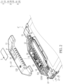
- FIG. 2 is a schematic exploded view of the portable electronic device according to the present invention
- the present invention provides a portable electronic device D, which includes a display body B, a rotatable component 1, and an optical communication module 2.
- the display body B includes a display screen B 1.
- the rotatable component 1 is pivotally connected to the display body B.
- the display body B is a tablet computer
- the rotatable component 1 is a rotatable handle that is installed to a side of the tablet computer.
- the display body B is not limited to being a particular type of electronic device in the present invention.
- the display body B can also be a notebook computer.
- the rotatable component 1 can rotate relative to the display body B.
- the optical communication module 2 is disposed inside the rotatable component 1 and communicates by the LI-FI technology.
- the optical communication module 2 includes a light emitter 21 and a light receiver 22, and a circuit board 23.
- the light emitter 21 and the light receiver 22 are disposed on and electrically connected to the circuit board 23.
- the rotatable component 1 has an opening 10, and the light emitter 21 and the light receiver 22 face the opening 10.
- the rotatable component 1 includes a first housing 11 and a second housing 12. That is, the first housing 11 and a second housing 12 are assembled with each other to form the rotatable component 1.
- the opening 10 is formed at the first housing 11.
- the light emitter 21 is an infrared light emitting diode (IR LED) that is capable of emitting infrared
- the light receiver 22 is a photodiode or a phototransistor that is used to receive an external light, such as the infrared.
- the optical communication module 2 can emit and receive other lights such as visible light or UV light.
- the rotatable component 1 can rotate relative to an axis L.
- the rotatable component 1 further includes a light-permeable member 3.
- the light-permeable member 3 has a flat shape and is disposed in the opening 10.
- the shape of the light-permeable member 3 is not limited in the present invention.
- the light-permeable member 3 is, for example, an IR pass filter which can allow infrared with wavelengths above 850 nm to pass there-through, but the present invention is not limited thereto.
- the type of the light-permeable member 3 is selected according to the type of light that is emitted and received by the optical communication module 2.
- the optical communication module 2 When the optical communication module 2 emits and receives visible light, the light-permeable member 3 only allows visible light with a specific wavelength to pass. When the optical communication module 2 emits and receives UV light, the light-permeable member 3 only allows UV light with a specific wavelength to pass. Therefore, the optical communication module 2 can emit and receive light with specific wavelengths through the configuration of the light-permeable member 3.
- the light-permeable member 3 covers the light emitter 21 and the light receiver 22. Moreover, projections of the light emitter 21 and the light receiver 22 that are projected onto the light-permeable member 3 completely overlap the light-permeable member 3, and projections of the light emitter 21 and the light receiver 22 that are projected onto the light-permeable member 3 is smaller than an area of the light-permeable member 3.
- the infrared that is generated by the light emitter 21 can pass through the light-permeable member 3 and then be emitted to external environment, specific external light such as the infrared with the wavelength above 850 nm can pass through the light-permeable member 3 and be received by the light receiver 22, and the infrared with the wavelength less than 850 nm is blocked by the light-permeable member 3.
- FIG. 3 is a schematic cross-sectional view taken along line III-III of FIG. 1
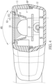
- FIG. 4 is a schematic cross-sectional view taken along line IV-IV of FIG. 1
- FIG. 5 is a schematic view of a first housing of the portable electronic device according to the present invention.
- the first housing 11 has a first inner annular wall 111 therein
- the second housing 12 has a second inner annular wall 121 therein.
- the first inner annular wall 111 and the second inner annular wall 121 jointly define an accommodating space SP.
- the opening 10 is in spatial communication with the accommodating space SP, and the optical communication module 2 is disposed in the accommodating space SP.
- the opening 10 tapers toward an interior of the rotatable component 1 (i.e., the accommodating space SP), such that an inner surface of the opening 10 forms an inclined wall P.
- the communication module 2 is disposed at the accommodating space SP, the light emitter 21 and the light receiver 22 of the communication module 2 are surround by the inclined wall P. Therefore, the inclined wall P can form a light mask, which concentrates the light incident from the external environment and is received by the optical communication module 2.
- the rotatable component 1 has a transverse section parallel to the cross-sectional view taken along line III-III and a longitudinal section parallel to the cross-sectional view taken along line IV-IV that are perpendicular to each other according to an extension direction of the axis L.
- the transverse section is parallel to the axis L
- the longitudinal section is perpendicular to the axis L.
- the longitudinal section is implemented in a form of a vertical line S1, and the longitudinal section (i.e., the vertical line S 1) and the inclined wall P form a first included angle ⁇ 1 therebetween.
- the transverse section is implemented in a form of a vertical line S2, and the transverse section (i.e., the vertical line S2) and the inclined wall P form a second included angle ⁇ 2 therebetween.
- the first included angle ⁇ 1 is greater than the second included angle ⁇ 2.
- the optical communication module 2 of the present invention is disposed inside the handle (i.e., the rotatable component 1), the size of the opening 10 is limited by the structure of the handle.
- the entry and exit of the light will not be interfered by the inclined wall P, such that the optical communication module 2 has an optimal light transmitting and receiving range.
- a light transmission and reception angle ⁇ 1 of the optical communication module 2 is greater than 45 degrees; in FIG. 4 , a light transmission and reception angle ⁇ 2 of the optical communication module 2 is greater than 35 degrees.
- the first housing 11 further includes a via hole 112.
- the rotatable component 1 further includes an identification member 15.
- the identification member 15 is disposed in the via hole 112. Specifically, one end of the identification member 15 is electrically connected to the circuit board 23, and another end of the identification member 15 passes through and is exposed from the first housing 11.
- a type of the identification member 15 is not limited in the present invention.
- the identification member 15 is, for example, a light pipe which can be connected to a light-emitting diode (LED) on the circuit board 23.
- the operation of the LED is linked with the optical communication module 2. For example, during the operation, the light is emitted by the LED through the light pipe (i.e., the identification member 15), so as to remind a user that the optical communication module 2 is transmitting and receiving signals.
- the portable electronic device D further includes a first pivot member 4 and a second pivot member 5 that are respectively disposed on two sides of the rotatable component 1.
- the first pivot member 4 is closer to a through hole 1210 of the second inner annular wall 121 than the second pivot member 5.
- the first pivot member 4 and the second pivot member 5 are configured to be connected to the display body B and the rotatable component 1.
- the first pivot member 4 includes a first casing 41 and a first rotating shaft 42.
- the first rotating shaft 42 is rotatably connected between the rotatable component 1 and the first casing 41.
- the first casing 41 is disposed on the display body B.
- the second pivot member 5 includes a second casing 51 and a second rotating shaft 52.
- the second casing 51 is disposed on the display body B.
- the second rotating shaft 52 is rotatably connected between the rotatable component 1 and the second casing 51. Therefore, the rotatable component 1 rotates relative to the first casing 41 and the second casing 51 through the first rotating shaft 42 and the second rotating shaft 52.
- a connecting line connecting the first rotating shaft 42 and the second rotating shaft 52 is the axis L. That is, the axis L is an axial line of the rotating shafts of the handle (i.e., the rotatable component 1).
- a center line C connecting the light emitter 21 and the light receiver 22 is parallel to the axis L. Therefore, when the handle (i.e., the rotatable component 1) rotates, the light emitter 21 and the light receiver 22 rotate at a same angle.
- the illumination of a light source is directly proportional to the brightness of the light source and inversely proportional to the distance from the light source. If the emitting distance of the light emitter 21 and the receiving distance of the light receiver 22 are inconsistent, the intensity of the transmitting and receiving signals by the optical communication module 2 will be affected.
- the emitting distance of the light emitter 21 and the receiving distance of the light receiver 22 are the same, such that the powers of the optical communication module 2 when emitting and receiving light remain consistent with each other.
- FIG. 6 is a schematic view of a first casing of the portable electronic device according to the present invention
- FIG. 7 is a second schematic view of the portable electronic device according to the present invention.
- FIG.1 shows a front side of the portable device D
- FIG. 7 shows a back side of the portable device D.
- a shape of the first casing 41 is different from a shape of the second casing 51.
- the first casing 41 includes a head portion 41A and a body portion 41B.
- the head portion 41A has an opening 412 for the first rotating shaft 42 to be inserted.
- the body portion 41B is a part of the first casing 41 that is used for connecting to the display body B.
- an internal space of the body portion 41B and an internal space of the display body B are in spatial communication with each other to allow wires for signal transmission to pass through.
- the second casing 51 also has an opening that is similar to the first casing 41 for the second rotating shaft 52 to be inserted, but the second casing 51 has no space for the wires to pass through.
- the first rotating shaft 42 can be inserted into the opening 412 of the head portion 41A, and the body portion 41B has enough space inside to accommodate other components.
- the second inner annular wall has a through hole 1210
- the rotatable component 1 further includes a first waterproof member 13 and a second waterproof member 14.
- the first waterproof member 13 is disposed at the through hole 1210.
- the second waterproof member 14 is disposed at a junction between the first inner annular wall 111 and the second inner annular wall 121.
- the first waterproof member 13 and the second waterproof member 14 are made of elastic waterproof rubber
- the first waterproof member 13 is a waterproof plug
- the second waterproof member 14 is an O-ring.
- the display body B further includes a control board B2.
- the control board B2 is electrically connected to the circuit board 23 through at least one conductive cable W. As shown in FIG. 7 , an extension direction of the at least one conductive cable W is indicated by a dotted line. One end of the at least one conductive cable W is electrically connected to the control board B2 inside the rotatable component 1.
- the control board B2 can be a central processing unit (CPU) or a network interface card, but the present invention is not limited thereto.
- Another end of the at least one conductive cable W passes through the through hole 1210 of the second inner annular wall 121 and the opening 412 of the head portion 41A, and is electrically connected to an interface 230 of an circuit board 23 inside the display body B after passing through the body portion 41B.
- first waterproof member 13 and the second waterproof member 14 External moisture can be prevented from penetrating into the accommodating space SP through the through hole 1210 or the junction between the first inner annular wall 111 and the second inner annular wall 121, resulting in the optical communication module 2 getting wet and causing a short circuit.
- a wall of the body portion 41 has a plurality of heat dissipation holes 410.
- the first casing 41 includes a cable tray 411 therein.
- the cable tray 411 is adjacent to the plurality of heat dissipation holes 410.
- the plurality of heat dissipation holes 410 are in communication with the internal space of the body portion 41B and the internal space of the display body B.
- the heat energy generated by the internal components of the display body B can be diffused through the plurality of heat dissipation holes 410 to improve the heat dissipation effect.
- the display body B includes a fan (not shown in the figures) therein, and the fan is close to the plurality of heat dissipation holes 410. Therefore, the heat dissipation effect can be further enhanced through the configuration of the fan.
- the at least one conductive cable W is used for being stored in the cable tray 411.
- a quantity of the conductive cable W is not limited in the present invention. When the quantity of the conductive cable W is plural, the conductive cables W can be organized and stored in the cable tray 411 to avoid breakage from being entangled with each other or excessively bent.
- the optical communication module 2 can be rotated to face the light source to easily transmit and receive signals through the rotatable structure of the rotatable component 1, and the range of the optical communication module 2 that transmits and receives signals can be increased.
- a light transmission and reception angle ⁇ 1 of the optical communication module 2 is greater than 45 degrees; in FIG. 4 , a light transmission and reception angle ⁇ 2 of the optical communication module 2 is greater than 35 degrees.
- a center line C connecting the light emitter 21 and the light receiver 22 is parallel to the axis L. Therefore, when the handle (i.e., the rotatable component 1) rotates, the light emitter 21 and the light receiver 22 rotate at a same angle.
- the illumination of a light source is directly proportional to the brightness of the light source and inversely proportional to the distance from the light source. If the emitting distance of the light emitter 21 and the receiving distance of the light receiver 22 are inconsistent, the intensity of the transmitting and receiving signals by the optical communication module 2 will be affected.
- the emitting distance of the light emitter 21 and the receiving distance of the light receiver 22 are the same, such that the powers of the optical communication module 2 when emitting and receiving light are consistent with each other.
Landscapes
- Engineering & Computer Science (AREA)
- Computer Hardware Design (AREA)
- Theoretical Computer Science (AREA)
- General Engineering & Computer Science (AREA)
- Physics & Mathematics (AREA)
- Human Computer Interaction (AREA)
- General Physics & Mathematics (AREA)
- Electromagnetism (AREA)
- Computer Networks & Wireless Communication (AREA)
- Signal Processing (AREA)
- Optical Communication System (AREA)
- Telephone Set Structure (AREA)
Abstract
Description
- The present invention relates to a portable electronic device, and more particularly to a portable electronic device having an optical communication module.
- Light Fidelity (Li-Fi) refers to the transmission of information using optical communication technology. For example, a visible light source (e.g., a light bulb) is used as a signal transmitter, and the light can be controlled by a controller to turn on and off, such as to control the communication between the signal transmitter and a terminal receiver.
- Currently, there are already examples of an optical communication module being applied to a portable electronic device, such as a notebook computer or a tablet computer. However, in the related art, the optical communication module is installed onto the portable electronic device such that light signals can only be transmitted and received at a fixed angle, which limits the communication range of the optical communication module. The optical communication module cannot receive light signals at a large angle, the quality of the communication is compromised.
- In addition, in the related art, the optical communication module is additionally installed on a periphery of the portable electronic device. In other words, the optical communication module will occupy the space around the portable electronic device, which can affect the arrangement of other components (e.g., USB interfaces).
- The present invention provides a portable electronic device having an optical communication module, which can address issues of the optical communication module occupying additional space and only being capable of transmitting and receiving signals at fixed angles.
- One of the technical aspects adopted by the present invention is to provide a portable electronic device, which includes a display body, a rotatable component, and an optical communication module. The display body includes a display screen. The rotatable component is pivotally connected to the display body. The rotatable component has an opening. The optical communication module is disposed inside the rotatable component. The optical communication module includes a light emitter and a light receiver, and the light emitter and the light receiver face the opening.
- Therefore, in the portable electronic device provided by the present invention, by virtue of the optical communication module being integrated into the rotatable component, the optical communication module can transmit and receive signals at different angles through the rotating structure of the rotatable component, such that the optical communication module can transmit and receive light signals at a large angle, and has good communication quality.
- The described embodiments may be better understood by reference to the following description and the accompanying drawings, in which:
-
FIG. 1 is a first schematic view of a portable electronic device according to the present invention; -
FIG. 2 is a schematic exploded view of the portable electronic device according to the present invention; -
FIG. 3 is a schematic cross-sectional view taken along line III-III ofFIG. 1 ; -
FIG. 4 is a schematic cross-sectional view taken along line IV-IV ofFIG. 1 ; -
FIG. 5 is a schematic view of a first housing of the portable electronic device according to the present invention; -
FIG. 6 is a schematic view of a first casing of the portable electronic device according to the present invention; and -
FIG. 7 is a second schematic view of the portable electronic device according to the present invention. - The present invention is more particularly described in the following examples that are intended as illustrative only since numerous modifications and variations therein will be apparent to those skilled in the art. Like numbers in the drawings indicate like components throughout the views. As used in the description herein and throughout the claims that follow, unless the context clearly dictates otherwise, the meaning of "a," "an" and "the" includes plural reference, and the meaning of "in" includes "in" and "on." Titles or subtitles can be used herein for the convenience of a reader.
- The terms used herein generally have their ordinary meanings in the art. In the case of conflict, the present document, including any definitions given herein, will prevail. The same thing can be expressed in more than one way. Alternative language and synonyms can be used for any term(s) discussed herein, and no special significance is to be placed upon whether a term is elaborated or discussed herein. A recital of one or more synonyms does not exclude the use of other synonyms. The use of examples anywhere in this specification including examples of any terms is illustrative only. Likewise, the present invention is not limited to various embodiments given herein. Numbering terms such as "first," "second" or "third" can be used to describe various components, signals or the like, which are for distinguishing one component/signal from another one only, and are not intended to, nor should be construed to impose any substantive limitations on the components, signals or the like.
- Referring to
FIG. 1 andFIG. 2 ,FIG. 1 is a first schematic view of a portable electronic device according to the present invention, andFIG. 2 is a schematic exploded view of the portable electronic device according to the present invention. The present invention provides a portable electronic device D, which includes a display body B, arotatable component 1, and an optical communication module 2. The display body B includes adisplay screen B 1. Therotatable component 1 is pivotally connected to the display body B. For example, the display body B is a tablet computer, and therotatable component 1 is a rotatable handle that is installed to a side of the tablet computer. However, the display body B is not limited to being a particular type of electronic device in the present invention. In other embodiments, the display body B can also be a notebook computer. Therotatable component 1 can rotate relative to the display body B. The optical communication module 2 is disposed inside therotatable component 1 and communicates by the LI-FI technology. - As shown in
FIG. 2 , the optical communication module 2 includes alight emitter 21 and alight receiver 22, and acircuit board 23. Thelight emitter 21 and thelight receiver 22 are disposed on and electrically connected to thecircuit board 23. Therotatable component 1 has anopening 10, and thelight emitter 21 and thelight receiver 22 face theopening 10. Furthermore, therotatable component 1 includes afirst housing 11 and asecond housing 12. That is, thefirst housing 11 and asecond housing 12 are assembled with each other to form therotatable component 1. The opening 10 is formed at thefirst housing 11. For example, thelight emitter 21 is an infrared light emitting diode (IR LED) that is capable of emitting infrared, and thelight receiver 22 is a photodiode or a phototransistor that is used to receive an external light, such as the infrared. However, the present invention is not limited thereto. In other embodiments, the optical communication module 2 can emit and receive other lights such as visible light or UV light. - As shown in
FIG. 1 andFIG. 2 , therotatable component 1 can rotate relative to an axis L. Therotatable component 1 further includes a light-permeable member 3. The light-permeable member 3 has a flat shape and is disposed in theopening 10. The shape of the light-permeable member 3 is not limited in the present invention. The light-permeable member 3 is, for example, an IR pass filter which can allow infrared with wavelengths above 850 nm to pass there-through, but the present invention is not limited thereto. The type of the light-permeable member 3 is selected according to the type of light that is emitted and received by the optical communication module 2. When the optical communication module 2 emits and receives visible light, the light-permeable member 3 only allows visible light with a specific wavelength to pass. When the optical communication module 2 emits and receives UV light, the light-permeable member 3 only allows UV light with a specific wavelength to pass. Therefore, the optical communication module 2 can emit and receive light with specific wavelengths through the configuration of the light-permeable member 3. - The light-permeable member 3 covers the
light emitter 21 and thelight receiver 22. Moreover, projections of thelight emitter 21 and thelight receiver 22 that are projected onto the light-permeable member 3 completely overlap the light-permeable member 3, and projections of thelight emitter 21 and thelight receiver 22 that are projected onto the light-permeable member 3 is smaller than an area of the light-permeable member 3. Therefore, the infrared that is generated by thelight emitter 21 can pass through the light-permeable member 3 and then be emitted to external environment, specific external light such as the infrared with the wavelength above 850 nm can pass through the light-permeable member 3 and be received by thelight receiver 22, and the infrared with the wavelength less than 850 nm is blocked by the light-permeable member 3. - Referring to
FIG. 3 to FIG. 5 ,FIG. 3 is a schematic cross-sectional view taken along line III-III ofFIG. 1 ,FIG. 4 is a schematic cross-sectional view taken along line IV-IV ofFIG. 1 , andFIG. 5 is a schematic view of a first housing of the portable electronic device according to the present invention. Thefirst housing 11 has a first innerannular wall 111 therein, and thesecond housing 12 has a second innerannular wall 121 therein. The first innerannular wall 111 and the second innerannular wall 121 jointly define an accommodating space SP. Theopening 10 is in spatial communication with the accommodating space SP, and the optical communication module 2 is disposed in the accommodating space SP. - As shown in
FIG. 3 to FIG. 5 , theopening 10 tapers toward an interior of the rotatable component 1 (i.e., the accommodating space SP), such that an inner surface of theopening 10 forms an inclined wall P. When the communication module 2 is disposed at the accommodating space SP, thelight emitter 21 and thelight receiver 22 of the communication module 2 are surround by the inclined wall P. Therefore, the inclined wall P can form a light mask, which concentrates the light incident from the external environment and is received by the optical communication module 2. - As shown in
FIG. 1 , therotatable component 1 has a transverse section parallel to the cross-sectional view taken along line III-III and a longitudinal section parallel to the cross-sectional view taken along line IV-IV that are perpendicular to each other according to an extension direction of the axis L. The transverse section is parallel to the axis L, and the longitudinal section is perpendicular to the axis L. - As shown in
FIG. 3 , since the transverse section and the longitudinal section are perpendicular to each other, the longitudinal section is implemented in a form of a vertical line S1, and the longitudinal section (i.e., the vertical line S 1) and the inclined wall P form a first included angle Θ1 therebetween. - Similarly, as shown in
FIG. 4 , since the transverse section and the longitudinal section are perpendicular to each other, the transverse section is implemented in a form of a vertical line S2, and the transverse section (i.e., the vertical line S2) and the inclined wall P form a second included angle Θ2 therebetween. Moreover, the first included angle Θ1 is greater than the second included angle Θ2. - Because the optical communication module 2 of the present invention is disposed inside the handle (i.e., the rotatable component 1), the size of the
opening 10 is limited by the structure of the handle. Through the design of an inclination angle of the inclined wall P, the entry and exit of the light will not be interfered by the inclined wall P, such that the optical communication module 2 has an optimal light transmitting and receiving range. For example, inFIG. 3 , a light transmission and reception angle Ø1 of the optical communication module 2 is greater than 45 degrees; inFIG. 4 , a light transmission and reception angle Ø2 of the optical communication module 2 is greater than 35 degrees. - As shown in
FIG. 2 , thefirst housing 11 further includes a viahole 112. Therotatable component 1 further includes anidentification member 15. Theidentification member 15 is disposed in the viahole 112. Specifically, one end of theidentification member 15 is electrically connected to thecircuit board 23, and another end of theidentification member 15 passes through and is exposed from thefirst housing 11. A type of theidentification member 15 is not limited in the present invention. Theidentification member 15 is, for example, a light pipe which can be connected to a light-emitting diode (LED) on thecircuit board 23. The operation of the LED is linked with the optical communication module 2. For example, during the operation, the light is emitted by the LED through the light pipe (i.e., the identification member 15), so as to remind a user that the optical communication module 2 is transmitting and receiving signals. - As shown in
FIG. 2 , the portable electronic device D further includes a first pivot member 4 and a second pivot member 5 that are respectively disposed on two sides of therotatable component 1. The first pivot member 4 is closer to a throughhole 1210 of the second innerannular wall 121 than the second pivot member 5. The first pivot member 4 and the second pivot member 5 are configured to be connected to the display body B and therotatable component 1. The first pivot member 4 includes afirst casing 41 and a firstrotating shaft 42. The firstrotating shaft 42 is rotatably connected between therotatable component 1 and thefirst casing 41. Thefirst casing 41 is disposed on the display body B. The second pivot member 5 includes asecond casing 51 and a secondrotating shaft 52. Thesecond casing 51 is disposed on the display body B. The secondrotating shaft 52 is rotatably connected between therotatable component 1 and thesecond casing 51. Therefore, therotatable component 1 rotates relative to thefirst casing 41 and thesecond casing 51 through the firstrotating shaft 42 and the secondrotating shaft 52. It is worth mentioning that a connecting line connecting the firstrotating shaft 42 and the secondrotating shaft 52 is the axis L. That is, the axis L is an axial line of the rotating shafts of the handle (i.e., the rotatable component 1). - In the present invention, a center line C connecting the
light emitter 21 and thelight receiver 22 is parallel to the axis L. Therefore, when the handle (i.e., the rotatable component 1) rotates, thelight emitter 21 and thelight receiver 22 rotate at a same angle. The illumination of a light source is directly proportional to the brightness of the light source and inversely proportional to the distance from the light source. If the emitting distance of thelight emitter 21 and the receiving distance of thelight receiver 22 are inconsistent, the intensity of the transmitting and receiving signals by the optical communication module 2 will be affected. Therefore, through thelight emitter 21 and thelight receiver 22 rotating at the same angle, the emitting distance of thelight emitter 21 and the receiving distance of thelight receiver 22 are the same, such that the powers of the optical communication module 2 when emitting and receiving light remain consistent with each other. - Referring to
FIG. 6 andFIG. 7 ,FIG. 6 is a schematic view of a first casing of the portable electronic device according to the present invention, andFIG. 7 is a second schematic view of the portable electronic device according to the present invention. ComparingFIG. 1 withFIG. 7 ,FIG.1 shows a front side of the portable device D, andFIG. 7 shows a back side of the portable device D. Specifically, a shape of thefirst casing 41 is different from a shape of thesecond casing 51. Thefirst casing 41 includes ahead portion 41A and abody portion 41B. Thehead portion 41A has anopening 412 for the firstrotating shaft 42 to be inserted. Thebody portion 41B is a part of thefirst casing 41 that is used for connecting to the display body B. An internal space of thebody portion 41B and an internal space of the display body B are in spatial communication with each other to allow wires for signal transmission to pass through. It should be noted that thesecond casing 51 also has an opening that is similar to thefirst casing 41 for the secondrotating shaft 52 to be inserted, but thesecond casing 51 has no space for the wires to pass through. - Through the structural design of dividing the
first housing 41 into thehead portion 41A and thebody portion 41B, the firstrotating shaft 42 can be inserted into theopening 412 of thehead portion 41A, and thebody portion 41B has enough space inside to accommodate other components. - In addition, the second inner annular wall has a through
hole 1210, and therotatable component 1 further includes a firstwaterproof member 13 and a secondwaterproof member 14. The firstwaterproof member 13 is disposed at the throughhole 1210. The secondwaterproof member 14 is disposed at a junction between the first innerannular wall 111 and the second innerannular wall 121. For example, the firstwaterproof member 13 and the secondwaterproof member 14 are made of elastic waterproof rubber, the firstwaterproof member 13 is a waterproof plug, and the secondwaterproof member 14 is an O-ring. - The display body B further includes a control board B2. The control board B2 is electrically connected to the
circuit board 23 through at least one conductive cable W. As shown inFIG. 7 , an extension direction of the at least one conductive cable W is indicated by a dotted line. One end of the at least one conductive cable W is electrically connected to the control board B2 inside therotatable component 1. For example, the control board B2 can be a central processing unit (CPU) or a network interface card, but the present invention is not limited thereto. Another end of the at least one conductive cable W passes through the throughhole 1210 of the second innerannular wall 121 and theopening 412 of thehead portion 41A, and is electrically connected to aninterface 230 of ancircuit board 23 inside the display body B after passing through thebody portion 41B. Through the configuration of the firstwaterproof member 13 and the secondwaterproof member 14, external moisture can be prevented from penetrating into the accommodating space SP through the throughhole 1210 or the junction between the first innerannular wall 111 and the second innerannular wall 121, resulting in the optical communication module 2 getting wet and causing a short circuit. - Reference is further made to
FIGS. 6 and7 . A wall of thebody portion 41 has a plurality of heat dissipation holes 410. Thefirst casing 41 includes acable tray 411 therein. Thecable tray 411 is adjacent to the plurality of heat dissipation holes 410. The plurality of heat dissipation holes 410 are in communication with the internal space of thebody portion 41B and the internal space of the display body B. The heat energy generated by the internal components of the display body B can be diffused through the plurality of heat dissipation holes 410 to improve the heat dissipation effect. Furthermore, the display body B includes a fan (not shown in the figures) therein, and the fan is close to the plurality of heat dissipation holes 410. Therefore, the heat dissipation effect can be further enhanced through the configuration of the fan. - In addition, the at least one conductive cable W is used for being stored in the
cable tray 411. A quantity of the conductive cable W is not limited in the present invention. When the quantity of the conductive cable W is plural, the conductive cables W can be organized and stored in thecable tray 411 to avoid breakage from being entangled with each other or excessively bent. - In conclusion, in the portable electronic device D provided by the present invention, by virtue of the optical communication module 2 being integrated into the
rotatable component 1, the optical communication module 2 can be rotated to face the light source to easily transmit and receive signals through the rotatable structure of therotatable component 1, and the range of the optical communication module 2 that transmits and receives signals can be increased. - Moreover, through the inclined wall P forming a light mask to surround the optical communication module 2 and the design of an inclination angle of the inclined wall P, the entry and exit of the light will not be interfered by the inclined wall P, such that the optical communication module 2 has an optimal light transmitting and receiving range. For example, in
FIG. 3 , a light transmission and reception angle Ø1 of the optical communication module 2 is greater than 45 degrees; inFIG. 4 , a light transmission and reception angle Ø2 of the optical communication module 2 is greater than 35 degrees. - In the present invention, a center line C connecting the
light emitter 21 and thelight receiver 22 is parallel to the axis L. Therefore, when the handle (i.e., the rotatable component 1) rotates, thelight emitter 21 and thelight receiver 22 rotate at a same angle. The illumination of a light source is directly proportional to the brightness of the light source and inversely proportional to the distance from the light source. If the emitting distance of thelight emitter 21 and the receiving distance of thelight receiver 22 are inconsistent, the intensity of the transmitting and receiving signals by the optical communication module 2 will be affected. Therefore, through thelight emitter 21 and thelight receiver 22 rotating at the same angle, the emitting distance of thelight emitter 21 and the receiving distance of thelight receiver 22 are the same, such that the powers of the optical communication module 2 when emitting and receiving light are consistent with each other. - The foregoing description of the exemplary embodiments of the invention has been presented only for the purposes of illustration and description and is not intended to be exhaustive or to limit the invention to the precise forms disclosed. Many modifications and variations are possible in light of the above teaching.
- The embodiments were chosen and described in order to explain the principles of the invention and their practical application so as to enable others skilled in the art to utilize the invention and various embodiments and with various modifications as are suited to the particular use contemplated.
Claims (15)
- A portable electronic device (D), characterized in comprising:a display body (B) including a display screen (B1);a rotatable component (1) pivotally connected to the display body (B), wherein the rotatable component (1) has an opening (10); andan optical communication module (2) disposed inside the rotatable component (1), wherein the optical communication module (2) includes a light emitter (21) and a light receiver (22), and the light emitter (21) and the light receiver (22) face the opening (10).
- The portable electronic device (D) according to claim 1, wherein the opening (10) tapers toward an interior of the rotatable component (1).
- The portable electronic device (D) according to claim 2, wherein an inner surface of the opening (10) forms an inclined wall (P), and the light emitter (21) and the light receiver (22) are surround by the inclined wall (P).
- The portable electronic device (D) according to claim 2, wherein the rotatable component (1) rotates relative to an axis (L), the rotatable component (1) has a transverse section and a longitudinal section, the transverse section is parallel to the axis (L), and the longitudinal section is perpendicular to the axis (L); wherein the longitudinal section and the inclined wall (P) form a first included angle (Θ1) therebetween, the transverse section and the inclined wall (P) form a second included angle (Θ2) therebetween, and the first included angle is greater than the second included angle.
- The portable electronic device (D) according to claim 1, wherein the rotatable component (1) includes a first housing (11) and a second housing (12) that are assembled with each other, the first housing (11) has a first inner annular wall (111), the second housing (12) has a second inner annular wall (121), the first inner annular wall (111) and the second inner annular wall (121) jointly define an accommodating space (SP), and the optical communication module (2) is disposed in the accommodating space (SP), the opening (10) is formed on the first housing (11), and the opening (10) is in spatial communication with the accommodating space (SP).
- The portable electronic device (D) according to claim 5, wherein the optical communication module (2) further includes a circuit board (23), and the light emitter (21) and the light receiver (22) are electrically connected to the circuit board (23).
- The portable electronic device (D) according to claim 6, wherein the rotatable component (1) further includes a first waterproof member (13) and a second waterproof member (14), the second inner annular wall (121) has a through hole (1210), the first waterproof member (13) is disposed at the through hole (1210), and the second waterproof member (14) is disposed at a junction between the first inner annular wall (111) and the second inner annular wall (121).
- The portable electronic device (D) according to claim 6, wherein the rotatable component (1) further includes an identification member (15), the identification member (15) is electrically connected to the circuit board (23), the first housing (11) further includes a via hole (112), and the identification member (15) is disposed in the via hole (112) and exposed from the first housing (11).
- The portable electronic device (D) according to claim 1, further comprising a light-permeable member (3), wherein the light-permeable member (3) is disposed in the opening (10), the light-permeable member (3) is configured to be penetrated by an infrared with a wavelength above 850 nm.
- The portable electronic device (D) according to claim 9, wherein orthogonal projections of the light emitter (21) and the light receiver (22) that are projected onto the light-permeable member (3) completely overlap the light-permeable member (3), and the orthogonal projections of the light emitter (21) and the light receiver (22) that are projected onto the light-permeable member (3) are smaller than an area of the light-permeable member (3).
- The portable electronic device (D) according to claim 1, further comprising a first pivot member (4) and a second pivot member (5) that are respectively disposed on two sides of the rotatable component (1), and the first pivot member (4) and the second pivot member (5) are configured to be connected to the display body (B) and the rotatable component (1).
- The portable electronic device (D) according to claim 11, wherein the first pivot member (4) includes a first casing (41) and a first rotating shaft (42), the first casing (41) is disposed on the display body (B), the first casing (41) has a plurality of heat dissipation holes (410), and the first rotating shaft (42) is connected between the rotatable component (1) and the first casing (41); wherein the second pivot member (5) includes a second casing (51) and a second rotating shaft (52), the second casing (51) is disposed on the display body (B), the second rotating shaft (52) is connected between the rotatable component (1) and the second casing (51); wherein the rotatable component (1) rotates relative to the first casing (41) and the second casing (51) through the first rotating shaft (42) and the second rotating shaft (52).
- The portable electronic device (D) according to claim 12, wherein the first casing (41) includes a cable tray (411) therein, and the cable tray (411) is adjacent to the plurality of heat dissipation holes (410).
- The portable electronic device (D) according to claim 13, wherein the display body (B) further includes a control board (23), the control board (23) is electrically connected to the circuit board (23) through at least one conductive cable (W), and the at least one conductive cable (W) is configured to be stored in the cable tray (411).
- The portable electronic device according to claim 11, wherein the first rotating shaft (42) and the second rotating shaft (52) are located on a same axis (L), the rotatable component (1) rotates relative to the axis (L), and a center line (C) connecting the light emitter (21) and the light receiver (22)is parallel to the axis (L).
Applications Claiming Priority (1)
| Application Number | Priority Date | Filing Date | Title |
|---|---|---|---|
| US202363531583P | 2023-08-09 | 2023-08-09 |
Publications (1)
| Publication Number | Publication Date |
|---|---|
| EP4506779A1 true EP4506779A1 (en) | 2025-02-12 |
Family
ID=90482336
Family Applications (1)
| Application Number | Title | Priority Date | Filing Date |
|---|---|---|---|
| EP24166317.8A Pending EP4506779A1 (en) | 2023-08-09 | 2024-03-26 | Portable electronic device |
Country Status (3)
| Country | Link |
|---|---|
| US (1) | US12613562B2 (en) |
| EP (1) | EP4506779A1 (en) |
| TW (1) | TWI858943B (en) |
Cited By (1)
| Publication number | Priority date | Publication date | Assignee | Title |
|---|---|---|---|---|
| EP4625102A1 (en) * | 2024-03-28 | 2025-10-01 | Getac Technology Corporation | Portable electronic device |
Citations (4)
| Publication number | Priority date | Publication date | Assignee | Title |
|---|---|---|---|---|
| US5781405A (en) * | 1996-09-30 | 1998-07-14 | Gateway 2000, Inc. | Electronic device having rotatably mounted infrared device with a pair of pegs fitting into a pair of holes |
| US20070076362A1 (en) * | 2005-09-30 | 2007-04-05 | Isaac Lagnado | Computer device having multi-function handle |
| US20090032420A1 (en) * | 2007-08-03 | 2009-02-05 | Sony Corporation | Waterproof case for electronic device |
| US20230123808A1 (en) * | 2021-10-19 | 2023-04-20 | Fositek Corporation | Hinge and an electronic device with the same |
Family Cites Families (18)
| Publication number | Priority date | Publication date | Assignee | Title |
|---|---|---|---|---|
| KR100286373B1 (en) * | 1997-10-17 | 2001-04-16 | 윤종용 | Portable computer for infrared data communication |
| JP2002215265A (en) | 2001-01-23 | 2002-07-31 | Hitachi Ltd | Portable information processing device |
| KR20040079134A (en) * | 2003-03-06 | 2004-09-14 | 삼성전자주식회사 | Desk top charger for bar type portable wireless terminal |
| US7565183B2 (en) * | 2004-11-15 | 2009-07-21 | Sony Ericsson Mobile Communications Ab | Mobile device with selectable camera position |
| TW200725141A (en) * | 2005-12-27 | 2007-07-01 | Benq Corp | Mobile electronic device |
| KR101366859B1 (en) * | 2007-10-31 | 2014-02-21 | 엘지전자 주식회사 | Portable terminal |
| EP2178276B1 (en) * | 2008-10-20 | 2014-07-30 | LG Electronics Inc. | Adaptation of recorded or shown image according to the orientation of a mobile terminal |
| CN202308698U (en) * | 2011-09-16 | 2012-07-04 | 旭丽电子(广州)有限公司 | Power switching device |
| US9699282B2 (en) * | 2013-03-29 | 2017-07-04 | Beijing Lenovo Software Ltd. | Electronic apparatus and control method |
| US10076254B2 (en) * | 2014-12-16 | 2018-09-18 | Microsoft Technology Licensing, Llc | Optical communication with optical sensors |
| CN105988519A (en) * | 2015-02-16 | 2016-10-05 | 联想(北京)有限公司 | Electronic device |
| US20190260863A1 (en) * | 2016-08-30 | 2019-08-22 | Xleap, Inc. | Information processing terminal |
| US10666357B2 (en) | 2016-11-23 | 2020-05-26 | Agency For Science, Technology And Research | Light emitting diode communication device, method of forming and operating the same |
| CN207457918U (en) | 2017-11-23 | 2018-06-05 | 广东益斯迈智能科技有限公司 | A kind of multifunctional man-machine interactive RFID industrial panel computers |
| CN208848115U (en) | 2018-09-20 | 2019-05-10 | 深圳中柏科技有限公司 | Portable computer and its concealed WiFi antenna structure |
| TWI678924B (en) * | 2018-10-26 | 2019-12-01 | 宏致電子股份有限公司 | Camera |
| TWI752513B (en) * | 2020-05-29 | 2022-01-11 | 香港商冠捷投資有限公司 | remote control |
| US11327237B2 (en) * | 2020-06-18 | 2022-05-10 | Apple Inc. | Display-adjacent optical emission or reception using optical fibers |
-
2023
- 2023-10-02 TW TW112137607A patent/TWI858943B/en active
-
2024
- 2024-03-14 US US18/604,749 patent/US12613562B2/en active Active
- 2024-03-26 EP EP24166317.8A patent/EP4506779A1/en active Pending
Patent Citations (4)
| Publication number | Priority date | Publication date | Assignee | Title |
|---|---|---|---|---|
| US5781405A (en) * | 1996-09-30 | 1998-07-14 | Gateway 2000, Inc. | Electronic device having rotatably mounted infrared device with a pair of pegs fitting into a pair of holes |
| US20070076362A1 (en) * | 2005-09-30 | 2007-04-05 | Isaac Lagnado | Computer device having multi-function handle |
| US20090032420A1 (en) * | 2007-08-03 | 2009-02-05 | Sony Corporation | Waterproof case for electronic device |
| US20230123808A1 (en) * | 2021-10-19 | 2023-04-20 | Fositek Corporation | Hinge and an electronic device with the same |
Non-Patent Citations (1)
| Title |
|---|
| SILICON LABS: "AN521", 31 January 2015 (2015-01-31) - 22 June 2024 (2024-06-22), pages 1 - 26, XP093177990, Retrieved from the Internet <URL:https://www.silabs.com/documents/public/application-notes/AN521.pdf> [retrieved on 20240622] * |
Cited By (1)
| Publication number | Priority date | Publication date | Assignee | Title |
|---|---|---|---|---|
| EP4625102A1 (en) * | 2024-03-28 | 2025-10-01 | Getac Technology Corporation | Portable electronic device |
Also Published As
| Publication number | Publication date |
|---|---|
| US12613562B2 (en) | 2026-04-28 |
| US20250053206A1 (en) | 2025-02-13 |
| TWI858943B (en) | 2024-10-11 |
| TW202507468A (en) | 2025-02-16 |
Similar Documents
| Publication | Publication Date | Title |
|---|---|---|
| TWI804039B (en) | Security camera system with angled cable attachment for increased downward-viewing angle | |
| US20190059142A1 (en) | Led security light with integrated motion sensor and motion sensing lighting system | |
| US12613562B2 (en) | Portable electronic device | |
| CN111010204B (en) | customer terminal equipment | |
| CN111010203B (en) | Client terminal device | |
| CN104347001B (en) | Display device | |
| US20040071410A1 (en) | Illuminant USB cable | |
| TW202012828A (en) | Flexible illuminating cable for power module | |
| KR102211153B1 (en) | Camera module type sensor apparatus and camera module | |
| CN114096780A (en) | Electronic device | |
| US5861815A (en) | Light bar and reflector assembly | |
| EP4625102A1 (en) | Portable electronic device | |
| TWI904617B (en) | Portable electronic device | |
| US20050082368A1 (en) | Wireless communication system capable of visually indicating failure of transmission and reception states | |
| TWI410682B (en) | Light guiding member, light emitting module with light guiding member and electronic device | |
| JP4834914B2 (en) | Luminescent display device | |
| CN213524980U (en) | Face lid subassembly and cleaning robot | |
| CN113659395B (en) | Light-emitting connector and data line | |
| TWI848416B (en) | Wiring device | |
| CN222783393U (en) | A waterproof, sound-permeable and optically-indicating structure | |
| CN219418268U (en) | Infrared emission device and electronic equipment | |
| US20250075896A1 (en) | Screen illumination device | |
| CN217690086U (en) | Identification device | |
| JPH11187392A (en) | Two-way optical communication device | |
| JP3099114U (en) | Optical mouse structure |
Legal Events
| Date | Code | Title | Description |
|---|---|---|---|
| PUAI | Public reference made under article 153(3) epc to a published international application that has entered the european phase |
Free format text: ORIGINAL CODE: 0009012 |
|
| STAA | Information on the status of an ep patent application or granted ep patent |
Free format text: STATUS: THE APPLICATION HAS BEEN PUBLISHED |
|
| AK | Designated contracting states |
Kind code of ref document: A1 Designated state(s): AL AT BE BG CH CY CZ DE DK EE ES FI FR GB GR HR HU IE IS IT LI LT LU LV MC ME MK MT NL NO PL PT RO RS SE SI SK SM TR |
|
| STAA | Information on the status of an ep patent application or granted ep patent |
Free format text: STATUS: REQUEST FOR EXAMINATION WAS MADE |
|
| 17P | Request for examination filed |
Effective date: 20250610 |
|
| STAA | Information on the status of an ep patent application or granted ep patent |
Free format text: STATUS: EXAMINATION IS IN PROGRESS |
|
| 17Q | First examination report despatched |
Effective date: 20260306 |