EP4506770A1 - Aircraft control - Google Patents

Aircraft control Download PDF

Info

Publication number
EP4506770A1
EP4506770A1 EP23190611.6A EP23190611A EP4506770A1 EP 4506770 A1 EP4506770 A1 EP 4506770A1 EP 23190611 A EP23190611 A EP 23190611A EP 4506770 A1 EP4506770 A1 EP 4506770A1
Authority
EP
European Patent Office
Prior art keywords
force
moment
local
control
aircraft
Prior art date
Legal status (The legal status is an assumption and is not a legal conclusion. Google has not performed a legal analysis and makes no representation as to the accuracy of the status listed.)
Pending
Application number
EP23190611.6A
Other languages
German (de)
French (fr)
Inventor
Valentin MACHANEK
Jens Dodenhöft
Matthias Meiner
Current Assignee (The listed assignees may be inaccurate. Google has not performed a legal analysis and makes no representation or warranty as to the accuracy of the list.)
Lilium GmbH
Original Assignee
Lilium GmbH
Priority date (The priority date is an assumption and is not a legal conclusion. Google has not performed a legal analysis and makes no representation as to the accuracy of the date listed.)
Filing date
Publication date
Application filed by Lilium GmbH filed Critical Lilium GmbH
Priority to EP23190611.6A priority Critical patent/EP4506770A1/en
Priority to PCT/EP2024/068618 priority patent/WO2025031676A1/en
Priority to CN202480052329.4A priority patent/CN121666562A/en
Priority to KR1020267007255A priority patent/KR20260049636A/en
Priority to AU2024321319A priority patent/AU2024321319A1/en
Publication of EP4506770A1 publication Critical patent/EP4506770A1/en
Pending legal-status Critical Current

Links

Images

Classifications

    • BPERFORMING OPERATIONS; TRANSPORTING
    • B64AIRCRAFT; AVIATION; COSMONAUTICS
    • B64CAEROPLANES; HELICOPTERS
    • B64C29/00Aircraft capable of landing or taking-off vertically, e.g. vertical take-off and landing [VTOL] aircraft
    • B64C29/0008Aircraft capable of landing or taking-off vertically, e.g. vertical take-off and landing [VTOL] aircraft having its flight directional axis horizontal when grounded
    • B64C29/0016Aircraft capable of landing or taking-off vertically, e.g. vertical take-off and landing [VTOL] aircraft having its flight directional axis horizontal when grounded the lift during taking-off being created by free or ducted propellers or by blowers
    • B64C29/0033Aircraft capable of landing or taking-off vertically, e.g. vertical take-off and landing [VTOL] aircraft having its flight directional axis horizontal when grounded the lift during taking-off being created by free or ducted propellers or by blowers the propellers being tiltable relative to the fuselage
    • BPERFORMING OPERATIONS; TRANSPORTING
    • B64AIRCRAFT; AVIATION; COSMONAUTICS
    • B64CAEROPLANES; HELICOPTERS
    • B64C39/00Aircraft not otherwise provided for
    • B64C39/12Canard-type aircraft
    • GPHYSICS
    • G05CONTROLLING; REGULATING
    • G05DSYSTEMS FOR CONTROLLING OR REGULATING NON-ELECTRIC VARIABLES
    • G05D1/00Control of position, course, altitude or attitude of land, water, air or space vehicles, e.g. using automatic pilots
    • G05D1/40Control within particular dimensions
    • G05D1/49Control of attitude, i.e. control of roll, pitch or yaw
    • BPERFORMING OPERATIONS; TRANSPORTING
    • B64AIRCRAFT; AVIATION; COSMONAUTICS
    • B64CAEROPLANES; HELICOPTERS
    • B64C13/00Control systems or transmitting systems for actuating flying-control surfaces, lift-increasing flaps, air brakes, or spoilers
    • B64C13/02Initiating means
    • B64C13/16Initiating means actuated automatically, e.g. responsive to gust detectors
    • BPERFORMING OPERATIONS; TRANSPORTING
    • B64AIRCRAFT; AVIATION; COSMONAUTICS
    • B64CAEROPLANES; HELICOPTERS
    • B64C9/00Adjustable control surfaces or members, e.g. rudders
    • B64C9/38Jet flaps
    • BPERFORMING OPERATIONS; TRANSPORTING
    • B64AIRCRAFT; AVIATION; COSMONAUTICS
    • B64DEQUIPMENT FOR FITTING IN OR TO AIRCRAFT; FLIGHT SUITS; PARACHUTES; ARRANGEMENT OR MOUNTING OF POWER PLANTS OR PROPULSION TRANSMISSIONS IN AIRCRAFT
    • B64D31/00Power plant control systems; Arrangement of power plant control systems in aircraft
    • B64D31/02Initiating means
    • B64D31/06Initiating means actuated automatically
    • GPHYSICS
    • G05CONTROLLING; REGULATING
    • G05DSYSTEMS FOR CONTROLLING OR REGULATING NON-ELECTRIC VARIABLES
    • G05D2105/00Specific applications of the controlled vehicles
    • G05D2105/20Specific applications of the controlled vehicles for transportation
    • G05D2105/22Specific applications of the controlled vehicles for transportation of humans
    • GPHYSICS
    • G05CONTROLLING; REGULATING
    • G05DSYSTEMS FOR CONTROLLING OR REGULATING NON-ELECTRIC VARIABLES
    • G05D2109/00Types of controlled vehicles
    • G05D2109/20Aircraft, e.g. drones
    • G05D2109/22Aircraft, e.g. drones with fixed wings
    • G05D2109/23Vertical take-off and landing [VTOL] aircraft; Short take-off and landing [STOL, STOVL] aircraft

Definitions

  • This invention relates to aircraft control, and in particular a computer implemented method for controlling an aircraft and an aircraft comprising a processor and memory storing computer code which, when executed on the processor, performs the method.
  • the allocation of force and moment commands on an aircraft with multi-purpose control effectors is a very complex, multi-dimensional problem. This is because a multi-purpose control effector may be used to generate forces and moments in all six degrees of freedom at the same time. Also, the relationship between a change of the control effector condition and the generation of forces and moments changes as a function of the airspeed, the environmental conditions, and the control effector condition itself.
  • the problem becomes yet more complex for vertical take-off and landing aircraft which are associated with highly nonlinear and coupled aerodynamic phenomena. These couplings and nonlinearities need to be captured by the allocation algorithm as accurately as possible.
  • the problem is complexified yet further if the control effector unit is controlled by a combination of actuators (for example, a propulsion unit installed inside a movable aerodynamic control surface).
  • the complexity of the control allocation algorithm requires storing a very large amount of data on the flight control computer(s), potentially exceeding the memory limitations of the computer(s) or requiring additional computing hardware to be installed on the aircraft.
  • the present invention seeks to at least partly ameliorate this problem.
  • a computer implemented method for controlling an aircraft comprising: determining a global force and/or moment allocation required to control movement of the aircraft, the global force and/or moment allocation relating to a net force and/or moment to act on the aircraft; determining a local force and/or moment allocation, the local force and/or moment allocation relating to a force and/or moment contribution to the net force provided by at least one of the control effectors; and controlling at least one of the control effectors to generate the determined local force and/or moment.
  • the global force and/or moment (which is the net of all forces contributions, including gravity, propulsion, and aerodynamic forces acting on the aircraft) is broken down and distributed to local forces (that is, force contributions to be generated by each of the respective control effectors to make up the global force/moment).
  • local forces that is, force contributions to be generated by each of the respective control effectors to make up the global force/moment.
  • the local control allocation problems can be solved by determining a set of parameters for each control effector that generate the local force contribution to the global force/moment.
  • the present invention yields a reduction in the required data by breaking the global force/moment allocation problem down into multiple local force/moment allocation problems.
  • This method therefore reduces the memory consumption of the control allocation algorithm thereby complying with the memory limitations of the flight control computer(s).
  • This method also reduces the complexity of the design of the control allocation algorithm and the complexity of the testing of the control allocation algorithm.
  • VTOL vertical take off and landing
  • Such aircraft typically include multi-purpose control effectors which generate forces and moments in multiple degrees of freedom.
  • Such multi-purpose control effectors, particularly those which generate forces and moments in more than two degrees of freedom, are much less commonly found in civil aircraft, if found at all.
  • the method may also comprise determining at least two local force and/or moment allocations relating to force and/or moment contributions to the net force provided by at least two control effectors.
  • the method involves breaking down the global force and/or moment allocation problem into at least two local force and/or moment allocation problems, for example one allocation problem for each wing in a pair of wings.
  • the allocation problem may cover multiple control effectors, for example one local allocation problem for a pair of canards, and another local allocation problem for a pair of wings. Breaking down the global allocation problem into multiple local allocation problems simplified the control allocation algorithm and yields a reduction of the data required to be stored on the flight control computer(s).
  • Each of the at least two local force and/or moment allocations may correspond to a different degree of freedom of the aircraft.
  • each of the local force and/or moment allocations may correspond to a different one of: an x-direction; a z-direction; a roll moment; a pitch moment; and a yaw moment. Breaking down the global allocation problem into multiple local allocation problems in this way further simplifies the control allocation algorithm.
  • Controlling the at least one of the control effectors may comprise adjusting at least one parameter of the control effectors to generate the local force and/or moment.
  • the parameters of the control effectors may include, for example, a flap angle or an engine rotor speed (effectively, an engine power).
  • the parameters may be determined by solving the local control allocation problems with reference to a simulation, the simulation providing information on the forces generated by the control effectors as a function of the control effector parameters.
  • the at least one parameter may be adjusted based, at least in part, on at least one condition external to the aircraft.
  • the local force and/or moment allocation may be determined based, at least in part, on at least one condition external to the aircraft.
  • the at least one parameter may be adjusted, and the local force and/or moment allocation may be determined, based at least in part on at least one of: airspeed; ambient air density; aerodynamic angle of attack; and the impact of the canards' operating conditions on the local forces generated by the wings (e.g., canard downwash/canard-wing interaction) which may be captured by scheduling the local force allocation on the wings over the canard operating conditions (i.e., canard flap angle and/or canard rotor speed).
  • the local force and/or moment allocation for one control effector may be determined, at least in part, to compensate for a force and/or moment generated by another control effector.
  • a force and/or moment generated by another control effector For example, an x-force generated by one control effector located above the centre of gravity of the aircraft may generate a downward pitch moment.
  • another control effector must compensate for this pitch moment by generating an opposing moment correction. This concept is described in more detail below with reference to Figures 5a and 5b .
  • the at least one control effector may comprise at least one engine.
  • the control effector may comprise at least one propulsion engine.
  • the control effector may include multiple engines, such as a plurality of engines arranged adjacent one another. The multiple engines may be arranged in pairs. The engines may be for example ducted electric vectored thrust engines.
  • the propulsion engine may be an electric propulsion engine with a ducted fan.
  • An electric propulsion engine can generate quicker changes in load than a comparable gas turbine engines for example. This is advantageous when controlling the control effectors to generate the local forces.
  • Controlling the at least one of the control effectors may comprise adjusting a thrust of the at least one propulsion engine.
  • the propulsion engine may provide an x-force or a z-force or a combination of both. The amount by which the engine thrust should be adjusted to generate a particular force may be determined with reference to a simulation.
  • the control effectors may comprise multiple propulsion engines, and the thrust of at least one of the propulsion engines may be adjusted based, at least in part, on the distance between that propulsion engine and the centre of mass of the aircraft. For example, to generate a given moment, the method may involve increasing the thrust of an engine near to the centre of gravity by a particular amount, or increasing the thrust of another engine further from the centre of gravity by a lower amount (because of the larger lever arm) to generate the moment.
  • the at least one control effector may comprise at least one control surface. Controlling the at least one of the control effectors may comprise adjusting an angle of the at least one control surface.
  • the control surface may be, for example, an aerodynamic surface of the aircraft such as a flap of a canard and/or a wing of the aircraft.
  • the control surface may be an adjustable flap of the aircraft. The adjustable flap may enable generating local aerodynamic z-forces to control movement of the aircraft in the z-direction and to generate pitch and roll moments.
  • the at least one control effector may comprise at least one engine mounted at or near the control surface, the position of the engine being movable with the control surface for variation of a thrust vector, specifically variation of the thrust vector direction.
  • the engine may be a propulsion engine mounted on or in an adjustable flap of a canard or a wing of an aircraft. When the angle of the flap (i.e., the control surface) is adjusted, the engine moves with the flap such that the direction of the thrust vector is also adjusted.
  • the engine may be essentially horizontal to provide an x-force.
  • the engine may be essentially vertical to provide a z-force. Between these extremes, the engine provides a force with an x-component and a z-component.
  • the control effectors may be located on wings and/or on canards of the aircraft.
  • the control effectors may be engines, such as propulsion engines, mounted within adjustable flaps of the canards and/or wings of the aircraft. In this way the control effectors can generate forces in multiple degrees of freedom by changing the angle of flaps generates aerodynamic forces as well as changing the angle of the thrust produced by the engines.
  • an aircraft comprising a processor and memory storing computer code which, when executed on the processor, performs the method as aforementioned.
  • any feature in one aspect of the invention may be applied to other aspects of the invention, in any appropriate combination.
  • method aspects may be applied to apparatus aspects, and vice versa.
  • any, some and/or all features in one aspect can be applied to any, some and/or all features in any other aspect, in any appropriate combination. It should also be appreciated that particular combinations of the various features described and defined in any aspects of the invention can be implemented and/or supplied and/or used independently.
  • any feature in one aspect of the invention may be applied to other aspects of the invention, in any appropriate combination.
  • method aspects may be applied to apparatus aspects, and vice versa.
  • means plus function features may be expressed alternatively in terms of their corresponding structure, such as a suitably programmed processor and associated memory.
  • Any apparatus feature as described herein may also be provided as a method feature, and vice versa.
  • features implemented in hardware may generally be implemented in software, and vice versa. Any reference to software and hardware features herein should be construed accordingly.
  • Figure 1 shows a vertical take-off and landing (VTOL) aircraft 10.
  • the aircraft 10 has a left canard 20 and a right canard 30 which respectively comprise a left canard control effector 22 and a right canard control effector 32.
  • the aircraft 10 also has as left wing 40 and a right canard 50 which respectively comprise a left wing control effector 42 and a right wing control effector 52.
  • the canards and wings extend from a fuselage of the aircraft, and the canards are located forward of the wings on the fuselage.
  • the aircraft has a centre of gravity (CG), also referred to herein as a centre of mass, which in this example is located slightly after the centre of the fuselage, towards the wings.
  • CG centre of gravity
  • the forward-backward axis of the aircraft is referred to herein as the "x" direction or “x” axis (as shown in Figure 1 ) and the term “x-forces” is used to refer to forces acting along the "x” direction.
  • the horizontal axis of the aircraft is referred to herein as the "y” direction or “y” axis (as shown in Figure 1 ) and the term “y-forces” is used to refer to forces acting along the "y” direction.
  • the vertical axis of the aircraft is referred to herein as the "z" direction or “z” axis (into or out of the page in Figure 1 ) and the term “z-forces” is used to refer to forces acting along the "z” direction.
  • the control effectors are multi-purpose control effectors in that they each effect movement of the aircraft in multiple degrees of freedom.
  • the control effectors comprise propulsion engines mounted within adjustable flaps on each of the canards and wings. Therefore, the control effectors each include an aerodynamic surface for effecting aerodynamic forces on the aircraft and one or more propulsion units for effecting thrust forces on the aircraft.
  • the propulsion units may provide a thrust force in a forward direction ("x" shown in Figure 1 ) when the aircraft is in a cruising configuration, or the propulsion units may provide a thrust force in a vertical direction ("z", into or out of the page in Figure 1 ) when the aircraft is in a take-off or landing configuration.
  • Each of the control effectors is located a distance away from the centre of gravity (CG) of the aircraft. Therefore, any force generated by the control effectors acts with a lever arm relative to the centre of gravity of the aircraft.
  • the lever arms associated with each control effector are as follows:
  • the subscript "C” when used herein refers to the canards, and the subscript “W” refers to the wings.
  • the subscript “CL” refers to the left canard
  • “CR” refers to the right canard
  • “WL” refers to the left wing
  • “WR” refers to the right wing.
  • the subscript “L” refers to roll moments
  • the subscript “M” refers to pitch moments
  • the subscript "N” refers to yaw moments.
  • the lateral lever arms for the generation of x-forces ( ⁇ y C,N and ⁇ y W,N in order to generate yaw moments) and z-forces ( ⁇ y C,L and ⁇ y W,L in order to generate roll moments) may be different.
  • the adjustable flaps rotate, the position of the engine relative to the centre of gravity will move.
  • the distance between the engines and the centre of gravity may be different when the engines are used to generate z-forces (e.g., when the engines are pointing downwards in the z-direction, when the aircraft is in a take-off or landing configuration) and when the engines are used to generate x-forces (e.g., when the engines are pointing backwards in the x-direction, when the aircraft is in a cruising configuration).
  • z-forces e.g., when the engines are pointing downwards in the z-direction, when the aircraft is in a take-off or landing configuration
  • x-forces e.g., when the engines are pointing backwards in the x-direction, when the aircraft is in a cruising configuration
  • Figures 2a to 4b show exemplary distributions of forces between the canards and the wings with different canard weighting factors.
  • Figures 2a , 3a , and 4a show distributions in which the force contribution of the canards is minimised, and the force contribution of the wings is maximised, in which case the canard weighing factor is at a minimum.
  • Figures 2b , 3b , and 4b show distributions in which the force contribution of the canards is maximised and the force contribution of the wings is minimised, in which case the canard weighing factor is at a maximum.
  • 100% of the global force may be provided by the canards and 0% by the wings, or vice versa.
  • Figures 2a and 2b show exemplary x-force distributions.
  • the x-forces are generated to the maximum extent possible by the control effectors 42, 52 located on the wings 40, 50 as indicated by the arrows in Figure 2a , with the control effectors 22, 32 located on the canards 20, 30 providing a minimal force contribution.
  • the x-forces are generated to the maximum extent possible by the control effectors 22, 32 located on the canards 20, 30 as indicated by the arrows in Figure 2b , with the control effectors 42, 52 located on the wings 40, 50 providing a minimal force contribution.
  • the canard weighting factor for the distribution of global x-forces between the canards and the wings is denoted by "k C,F x ".
  • Figures 3a and 3b show exemplary x-force distributions for generating a roll moment.
  • the z-forces required to generate a roll moment are generated to the maximum extent possible by the control effectors 42, 52 located on the wings 40, 50 as indicated by the arrows in Figure 3a , with the control effectors 22, 32 located on the canards 20, 30 providing a minimal force contribution.
  • the z-forces required to generate a roll moment are generated to the maximum extent possible by the control effectors 22, 32 located on the canards 20, 30 as indicated by the arrows in Figure 3b , with the control effectors 42, 52 located on the wings 40, 50 providing a minimal force contribution.
  • the force contributions provided by the left and right control effectors are in opposite directions in the z-axis thereby to generate the roll moment about the x-axis without generating a net z-force on the aircraft level.
  • the canard weighting factor for the distribution of roll moment forces between the canards and the wings is denoted by " k C,L ".
  • Figures 4a and 4b show exemplary x-force distributions for generating a yaw moment.
  • the x-forces required to generate a yaw moment are generated to the maximum extent possible by the control effectors 42, 52 located on the wings 40, 50 as indicated by the arrows in Figure 4a , with the control effectors 22, 32 located on the canards 20, 30 providing a minimal force contribution.
  • the x-forces required to generate a yaw moment are generated to the maximum extent possible by the control effectors 22, 32 located on the canards 20, 30 as indicated by the arrows in Figure 4b , with the control effectors 42, 52 located on the wings 40, 50 providing a minimal force contribution.
  • the force contributions provided by the left and right control effectors are in opposite directions in the x-axis thereby to generate the yaw moment about the z-axis without generating a net force in the x-direction.
  • the canard weighting factor for the distribution of yaw moment forces between the canards and the wings is denoted by " k C,N ".
  • Figures 2a to 4b show extreme cases where the either a maximum or minimum force contribution is provided by either the canards or the wings, in many cases both the canards and the wings will provide some a contribution to the global force that is somewhere between the maximum and minimum contribution, with the distribution of forces between the canards and the wings being determined by the canard weighting factor.
  • Figures 5a and 5b show an exemplary distribution of global x-forces to local x-forces at each control effector.
  • the distributed x-forces in this example generate a pitch moment that requires correction.
  • the distribution of global x-forces between the local x-forces on the canard and the local x-forces on the wing can generally be arbitrary and is determined by the corresponding canard weighting factor k C,F x .
  • the canard weighting factor in this case can be selected arbitrarily.
  • the x-direction force command vector ⁇ F x,local,cmd,F x ( F x,global,cmd ) will be: 0.2 F x , global , cmd 0.2 F x , global , cmd 0.3 F x , global , cmd 0.3 F x , global , cmd .
  • each of the two canards provides a 20% contribution of the global force
  • each of the two wings provides a 30% contribution to the global force.
  • the total of all four local force contributions is 100% of the global force.
  • the control effectors may be offset from the centre of gravity in the z-direction, and the degree of the offset might change depending on the flap position (which changes with the airspeed).
  • the control effectors located on the wings are offset from the centre of gravity (CG) by a distance of ⁇ z W .
  • This offset means that the force contribution provided by the left and right wings also generates a downward pitch moment. In order to counteract this moment, a pitch correction may be introduced.
  • control effectors located on the canards are not offset from the centre of gravity in the z-direction in the example shown in Figures 5a and 5b , but in other examples they may be offset by a distance of ⁇ z c which may either contribute to the pitch coupling generated by the wing control effectors or counteract the pitch coupling (depending on whether ⁇ z c is the same direction or the opposite direction to ⁇ z W ).
  • Figure 6 shows an exemplary distribution of global z-forces to local z-forces at each control effector.
  • the distribution of z-forces in this example is determined to prevent generating any moment on the aircraft.
  • the weighting of distribution of z-forces between the canards and the wings i.e., the canard weighting factor
  • the canard weighting factor cannot be arbitrary, as it can be for the distribution of x-forces.
  • Applying an arbitrary canard weighting first and correcting for moments in a second step is less preferable as both global z-forces (to affect the z-movement of the aircraft) and pitch moments are eventually distributed to local z-forces.
  • the z-force components distributed to the canards are proportionally smaller than the force components distributed to the wings because the position of the centre of gravity is located on the fuselage slightly closer to the wings than to the canards.
  • global moment commands can be represented as local force contributions. Moments are always generated when local forces are generated by the control effectors at a lever arm from the centre of gravity.
  • the present control method makes use of this relationship. Similar to the distribution of global x-force commands, the breakdown of global z-force commands to local z-force command contributions can be described in a mathematical form. In particular, an equation for distributing the global z-force to local z-forces can be derived as follows.
  • the global z-force acting on the aircraft ( F z,global,cmd ) is given by the sum of the z-forces generated by each of the two canards (i.e., 2 ⁇ F z,local,C ) and by each of the two wings (i.e., 2 ⁇ F z,local,W ).
  • Equation ( II ) can be rearranged and rewritten as shown in equation ( III ) below:
  • F z , local , C F z , local , W ⁇ ⁇ x W ⁇ x C
  • the canard weighting factor k F z ⁇ x C + ⁇ x W ⁇ x C , or in other words it is the ratio of the sum of the canard and wing lever arms to the canard lever arm. Therefore, the closer centre of gravity to the wings, the smaller ⁇ x W will be and the canard weighting factor will tend towards 1, meaning that the first and second elements of the distribution vector 1 ⁇ 1 k F z will tend towards 0 and the third and fourth elements of the distribution vector will tend towards 1 thereby producing a command vector that distributes z-forces to the wings more than to the canards.
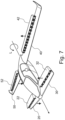
  • Figure 7 shows an exemplary distribution of roll moment commands to local z-forces at each control effector.
  • the distribution of a roll moment command to local z-forces is defined as a function of the corresponding canard weighting.
  • the local force commands for the left canard and right canard have the same magnitude, but with different signs. The same holds true for the left and right wings.
  • Both local force commands on the left side of the aircraft i.e., the left canard and the left wing
  • the same applies to the right side of the aircraft i.e., the right canard and right wing).
  • Figure 8 shows an exemplary distribution of pitch moment commands to local z-forces at each control effector.
  • the net z-force acting on the aircraft ( F z,residual ) is given by the sum of the z-forces generated by each of the two canards (i.e., 2 ⁇ F z,local,C ) and by each of the two wings (i.e., 2 ⁇ F z,local,W ).
  • the pitch moment generated by each of the two canards and the two wings is given by multiplying the force generated by each canard or wing by its lever arm from the centre of gravity ( ⁇ x C and ⁇ x W respectively).
  • Figure 9 shows an exemplary distribution of yaw moment commands to local z-forces at each control effector.
  • the yaw moment command distribution is very similar to the distribution of roll moment commands. In contrast however, the moment is distributed to local x-forces rather than local z-forces.
  • both canard contributions have the same magnitude, and so do the wing contributions, but the contributions by the control effectors on the left-hand side are in the opposite direction to the contributions by the control effectors on the right-hand side. Canard and wing contributions for the same side of the aircraft have the same sign.
  • each local force contribution described above is a 4 x 1 vector where each of the four elements represents one of the two canards and two wings.
  • the total x-force command therefore includes two components: the total global x-force commands ( F x,local,cmd,F x ) and yaw moment commands ( F x,local,cmd,N ).
  • the total z-force command therefore includes three components: the total global z-force commands ( F z,local,cmd,F z ), the roll moment commands ( ⁇ F z,local,cmd,L ) and the pitch moment commands ( F z,local,cmd,M ).
  • control effectors which, according to an aircraft simulation model, generate the required combination of local x-forces and local z-forces.
  • the control effects are propulsion engines mounted in adjustable flaps.
  • the parameters of the control effectors include: (a) a flap angle and (b) an engine power (essentially, engine rotor speed). In case of another aircraft configuration, different control effectors may be used having different adjustable parameters for generating forces.
  • each canard and each wing may apply the same flap angle command and rotor speed command to all the flaps and engines within that wing/canard.
  • the local force problem is deterministic and is solved by finding a combination of two actuator states (i.e. one flap angle state and one rotor speed state) that generate a combination of the required local x-forces and local z-forces.
  • the flap angle or rotor speed commands may be different for different engines within the wing/canard.
  • the thrust (i.e., rotor speed) of at least one of the propulsion engines within a wing/canard may be adjusted depending, at least in part, on the distance between that engine and the centre of mass of the aircraft. In this example, the moment can be increased by increasing the rotor speeds of engines located furthest from the centre of mass.
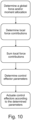
  • Figure 10 shows a flow diagram of the steps of the method described herein.
  • a global force and/or moment allocation required to control movement of an aircraft is determined.
  • the global force and/or moment allocation relates to a net force and/or moment to act on the aircraft. For example, if it is required that the aircraft moves forward and upward, the global force relates to the net x-force required to move the aircraft forward by the desired amount and the net z-force to move the aircraft upward by the desired amount.
  • a local force and/or moment allocation is determined.
  • the local force and/or moment allocation relates to the force and/or moment contribution to the net force provided by at least one of the control effectors.
  • the local force and/or moment allocation represents the individual local force contributions provided by each control effector.
  • the global x-forces and z-forces are broken down into individual local x-force and z-force contributions as described above in the sections headed "Distribution of global x-forces to local x-forces" and "Distribution of global z-forces to local z-forces".
  • the moments are broken down into individual local x-force and z-force contributions as described above in the sections headed "Distribution of roll moment commands to local z-forces", “Distribution of pitch moment commands to local z-forces” and “Distribution of yaw moment commands to local z-forces”.
  • a third step the local x-force and z-force contributions from each control effector are summed to provide the total force contributions required from each control effector to provide the global forces and moments required in the first step.
  • control allocation problems are solved to determine control effector parameters that generate the required combination of local x-forces and local z-forces.
  • these parameters may be a flap angle for each of the canards and wings, and a rotor speed for the engines located in the flaps, which will generate the x-forces and z-forces required at each canard/wing.
  • control effectors are actuated according to the determined parameters to generate the determined local forces and/or moments.
  • the flap is adjusted to the determined flap angle, and the engine rotor speed is adjusted to the determined level.
  • the concepts can also be applied to other aircraft configurations.
  • the concepts may be applied to aircraft with means to generate lateral forces (in the y-direction) directly through appropriate control devices.

Landscapes

  • Engineering & Computer Science (AREA)
  • Aviation & Aerospace Engineering (AREA)
  • Radar, Positioning & Navigation (AREA)
  • Remote Sensing (AREA)
  • Physics & Mathematics (AREA)
  • General Physics & Mathematics (AREA)
  • Automation & Control Theory (AREA)
  • Mechanical Control Devices (AREA)
  • Control Of Position, Course, Altitude, Or Attitude Of Moving Bodies (AREA)
  • Feedback Control In General (AREA)

Abstract

The invention relates to a computer implemented method for controlling an aircraft, the aircraft having multiple control effectors, the method comprising: determining a global force and/or moment allocation required to control movement of the aircraft, the global force and/or moment allocation relating to a net force and/or moment to act on the aircraft; determining a local force and/or moment allocation, the local force and/or moment allocation relating to a force and/or moment contribution to the net force provided by at least one of the control effectors; and controlling at least one of the control effectors to generate the determined local force and/or moment. The invention also relates to an aircraft comprising a processor and memory storing computer code which, when executed on the processor, performs the method.

Description

    Field of Invention
  • This invention relates to aircraft control, and in particular a computer implemented method for controlling an aircraft and an aircraft comprising a processor and memory storing computer code which, when executed on the processor, performs the method.
  • Background
  • The allocation of force and moment commands on an aircraft with multi-purpose control effectors is a very complex, multi-dimensional problem. This is because a multi-purpose control effector may be used to generate forces and moments in all six degrees of freedom at the same time. Also, the relationship between a change of the control effector condition and the generation of forces and moments changes as a function of the airspeed, the environmental conditions, and the control effector condition itself. The problem becomes yet more complex for vertical take-off and landing aircraft which are associated with highly nonlinear and coupled aerodynamic phenomena. These couplings and nonlinearities need to be captured by the allocation algorithm as accurately as possible. The problem is complexified yet further if the control effector unit is controlled by a combination of actuators (for example, a propulsion unit installed inside a movable aerodynamic control surface).
  • The complexity of the control allocation algorithm requires storing a very large amount of data on the flight control computer(s), potentially exceeding the memory limitations of the computer(s) or requiring additional computing hardware to be installed on the aircraft.
  • The present invention seeks to at least partly ameliorate this problem.
  • Summary of the Invention
  • Aspects and embodiments of the present invention are set out in the appended claims. These and other aspects and embodiments of the invention are also described herein.
  • The above described problem is solved by a computer implemented method for controlling an aircraft, the aircraft having multiple control effectors, the method comprising: determining a global force and/or moment allocation required to control movement of the aircraft, the global force and/or moment allocation relating to a net force and/or moment to act on the aircraft; determining a local force and/or moment allocation, the local force and/or moment allocation relating to a force and/or moment contribution to the net force provided by at least one of the control effectors; and controlling at least one of the control effectors to generate the determined local force and/or moment.
  • Therefore, with the present invention, the global force and/or moment (which is the net of all forces contributions, including gravity, propulsion, and aerodynamic forces acting on the aircraft) is broken down and distributed to local forces (that is, force contributions to be generated by each of the respective control effectors to make up the global force/moment). In this way, the complex global control allocation problem can be broken down into several simpler local control allocation problems. The local control allocation problems can be solved by determining a set of parameters for each control effector that generate the local force contribution to the global force/moment.
  • Advantageously, the present invention yields a reduction in the required data by breaking the global force/moment allocation problem down into multiple local force/moment allocation problems. This method therefore reduces the memory consumption of the control allocation algorithm thereby complying with the memory limitations of the flight control computer(s). This method also reduces the complexity of the design of the control allocation algorithm and the complexity of the testing of the control allocation algorithm.
  • While the present invention can be applied to a variety of aircraft configurations, the invention is particularly advantageous when applied to vertical take off and landing (VTOL) aircraft. This is because such aircraft typically include multi-purpose control effectors which generate forces and moments in multiple degrees of freedom. Such multi-purpose control effectors, particularly those which generate forces and moments in more than two degrees of freedom, are much less commonly found in civil aircraft, if found at all.
  • The method may also comprise determining at least two local force and/or moment allocations relating to force and/or moment contributions to the net force provided by at least two control effectors. In this way, the method involves breaking down the global force and/or moment allocation problem into at least two local force and/or moment allocation problems, for example one allocation problem for each wing in a pair of wings. Alternatively, the allocation problem may cover multiple control effectors, for example one local allocation problem for a pair of canards, and another local allocation problem for a pair of wings. Breaking down the global allocation problem into multiple local allocation problems simplified the control allocation algorithm and yields a reduction of the data required to be stored on the flight control computer(s).
  • Each of the at least two local force and/or moment allocations may correspond to a different degree of freedom of the aircraft. For example, each of the local force and/or moment allocations may correspond to a different one of: an x-direction; a z-direction; a roll moment; a pitch moment; and a yaw moment. Breaking down the global allocation problem into multiple local allocation problems in this way further simplifies the control allocation algorithm.
  • Controlling the at least one of the control effectors may comprise adjusting at least one parameter of the control effectors to generate the local force and/or moment. The parameters of the control effectors may include, for example, a flap angle or an engine rotor speed (effectively, an engine power). The parameters may be determined by solving the local control allocation problems with reference to a simulation, the simulation providing information on the forces generated by the control effectors as a function of the control effector parameters.
  • The at least one parameter may be adjusted based, at least in part, on at least one condition external to the aircraft. Similarly, the local force and/or moment allocation may be determined based, at least in part, on at least one condition external to the aircraft. In particular, the at least one parameter may be adjusted, and the local force and/or moment allocation may be determined, based at least in part on at least one of: airspeed; ambient air density; aerodynamic angle of attack; and the impact of the canards' operating conditions on the local forces generated by the wings (e.g., canard downwash/canard-wing interaction) which may be captured by scheduling the local force allocation on the wings over the canard operating conditions (i.e., canard flap angle and/or canard rotor speed).
  • The local force and/or moment allocation for one control effector may be determined, at least in part, to compensate for a force and/or moment generated by another control effector. For example, an x-force generated by one control effector located above the centre of gravity of the aircraft may generate a downward pitch moment. Thus, another control effector must compensate for this pitch moment by generating an opposing moment correction. This concept is described in more detail below with reference to Figures 5a and 5b.
  • The at least one control effector may comprise at least one engine. In particular, the control effector may comprise at least one propulsion engine. The control effector may include multiple engines, such as a plurality of engines arranged adjacent one another. The multiple engines may be arranged in pairs. The engines may be for example ducted electric vectored thrust engines.
  • The propulsion engine may be an electric propulsion engine with a ducted fan. An electric propulsion engine can generate quicker changes in load than a comparable gas turbine engines for example. This is advantageous when controlling the control effectors to generate the local forces.
  • Controlling the at least one of the control effectors may comprise adjusting a thrust of the at least one propulsion engine. Depending on the angle of the engine relative to the aircraft canard or wing, the propulsion engine may provide an x-force or a z-force or a combination of both. The amount by which the engine thrust should be adjusted to generate a particular force may be determined with reference to a simulation.
  • The control effectors may comprise multiple propulsion engines, and the thrust of at least one of the propulsion engines may be adjusted based, at least in part, on the distance between that propulsion engine and the centre of mass of the aircraft. For example, to generate a given moment, the method may involve increasing the thrust of an engine near to the centre of gravity by a particular amount, or increasing the thrust of another engine further from the centre of gravity by a lower amount (because of the larger lever arm) to generate the moment.
  • The at least one control effector may comprise at least one control surface. Controlling the at least one of the control effectors may comprise adjusting an angle of the at least one control surface. The control surface may be, for example, an aerodynamic surface of the aircraft such as a flap of a canard and/or a wing of the aircraft. In particular, the control surface may be an adjustable flap of the aircraft. The adjustable flap may enable generating local aerodynamic z-forces to control movement of the aircraft in the z-direction and to generate pitch and roll moments.
  • The at least one control effector may comprise at least one engine mounted at or near the control surface, the position of the engine being movable with the control surface for variation of a thrust vector, specifically variation of the thrust vector direction. For example, the engine may be a propulsion engine mounted on or in an adjustable flap of a canard or a wing of an aircraft. When the angle of the flap (i.e., the control surface) is adjusted, the engine moves with the flap such that the direction of the thrust vector is also adjusted. In one extreme position, the engine may be essentially horizontal to provide an x-force. In another extreme position, the engine may be essentially vertical to provide a z-force. Between these extremes, the engine provides a force with an x-component and a z-component.
  • The control effectors may be located on wings and/or on canards of the aircraft. In particular, the control effectors may be engines, such as propulsion engines, mounted within adjustable flaps of the canards and/or wings of the aircraft. In this way the control effectors can generate forces in multiple degrees of freedom by changing the angle of flaps generates aerodynamic forces as well as changing the angle of the thrust produced by the engines.
  • According to another aspect disclosed herein, there is provided an aircraft comprising a processor and memory storing computer code which, when executed on the processor, performs the method as aforementioned.
  • Any feature in one aspect of the invention may be applied to other aspects of the invention, in any appropriate combination. In particular, method aspects may be applied to apparatus aspects, and vice versa. Furthermore, any, some and/or all features in one aspect can be applied to any, some and/or all features in any other aspect, in any appropriate combination. It should also be appreciated that particular combinations of the various features described and defined in any aspects of the invention can be implemented and/or supplied and/or used independently.
  • Any feature in one aspect of the invention may be applied to other aspects of the invention, in any appropriate combination. In particular, method aspects may be applied to apparatus aspects, and vice versa. As used herein, means plus function features may be expressed alternatively in terms of their corresponding structure, such as a suitably programmed processor and associated memory. Any apparatus feature as described herein may also be provided as a method feature, and vice versa. Furthermore, features implemented in hardware may generally be implemented in software, and vice versa. Any reference to software and hardware features herein should be construed accordingly.
  • The invention extends to methods, system and apparatus substantially as herein described and/or as illustrated with reference to the accompanying figures.
  • One or more aspects of the present invention will now be described, by way of example only, and with reference to the accompanying drawings, in which:
    • Figure 1 is a plan view of an exemplary aircraft with multiple control effectors;
    • Figures 2a and 2b show exemplary distributions of x-forces between the control effectors;
    • Figures 3a and 3b show exemplary distributions of z-forces between the control effectors generating roll moments;
    • Figures 4a and 4b show exemplary distributions of x-forces between the control effectors generating yaw moments;
    • Figures 5a and 5b show a distribution of x-forces between the control effectors generating a pitch moment;
    • Figure 6 shows a distribution of z-forces between the control effectors generating no overall moment;
    • Figure 7 shows a distribution of z-forces between the control effectors generating an overall roll moment;
    • Figure 8 shows a distribution of z-forces between the control effectors generating an overall pitch moment;
    • Figure 9 shows a distribution of x-forces between the control effectors generating an overall yaw moment; and
    • Figure 10 shows a flow diagram of the steps of the method described herein.
    Detailed description
  • Figure 1 shows a vertical take-off and landing (VTOL) aircraft 10. The aircraft 10 has a left canard 20 and a right canard 30 which respectively comprise a left canard control effector 22 and a right canard control effector 32. The aircraft 10 also has as left wing 40 and a right canard 50 which respectively comprise a left wing control effector 42 and a right wing control effector 52. The canards and wings extend from a fuselage of the aircraft, and the canards are located forward of the wings on the fuselage. The aircraft has a centre of gravity (CG), also referred to herein as a centre of mass, which in this example is located slightly after the centre of the fuselage, towards the wings.
  • The forward-backward axis of the aircraft is referred to herein as the "x" direction or "x" axis (as shown in Figure 1) and the term "x-forces" is used to refer to forces acting along the "x" direction. The horizontal axis of the aircraft is referred to herein as the "y" direction or "y" axis (as shown in Figure 1) and the term "y-forces" is used to refer to forces acting along the "y" direction. The vertical axis of the aircraft is referred to herein as the "z" direction or "z" axis (into or out of the page in Figure 1) and the term "z-forces" is used to refer to forces acting along the "z" direction.
  • The control effectors (22, 32, 42, 52) are multi-purpose control effectors in that they each effect movement of the aircraft in multiple degrees of freedom. Specifically, the control effectors comprise propulsion engines mounted within adjustable flaps on each of the canards and wings. Therefore, the control effectors each include an aerodynamic surface for effecting aerodynamic forces on the aircraft and one or more propulsion units for effecting thrust forces on the aircraft. For example, the propulsion units may provide a thrust force in a forward direction ("x" shown in Figure 1) when the aircraft is in a cruising configuration, or the propulsion units may provide a thrust force in a vertical direction ("z", into or out of the page in Figure 1) when the aircraft is in a take-off or landing configuration.
  • Each of the control effectors is located a distance away from the centre of gravity (CG) of the aircraft. Therefore, any force generated by the control effectors acts with a lever arm relative to the centre of gravity of the aircraft. The lever arms associated with each control effector, as shown in Figure 1, are as follows:
    • ΔxC is the effective canard lever arm in the x-direction with respect to the centre of gravity when generating z-forces
    • ΔxW is the effective wing lever arm in the x-direction with respect to the centre of gravity when generating z-forces
    • ΔyC,L is the effective canard lever arm in the y-direction with respect to the centre of gravity when generating z-forces to effect a roll moment
    • ΔyW,L is the effective wing lever arm in the y-direction with respect to the centre of gravity when generating z-forces to effect a roll moment
    • ΔyC,N is the effective canard lever arm in the y-direction with respect to the centre of gravity when generating x-forces to effect a yaw moment
    • ΔyW,N is the effective wing lever arm in the y-direction with respect to the centre of gravity when generating x-forces to effect a yaw moment
  • Additional relevant lever arms described herein, but not shown in Figure 1, are as follows:
    • ΔzC is the effective canard lever arm in the z-direction with respect to the centre of gravity which generates pitch coupling (which requires correction) when generating x-forces as described below with reference to Figures 5a and 5b
    • ΔzW is the effective wing lever arm in z-direction with respect to the centre of gravity which generates pitch coupling (which requires correction) when generating x-forces as described below with reference to Figures 5a and 5b
  • The subscript "C" when used herein refers to the canards, and the subscript "W" refers to the wings. The subscript "CL" refers to the left canard, "CR" refers to the right canard, "WL" refers to the left wing, and "WR" refers to the right wing. The subscript "L" refers to roll moments, the subscript "M" refers to pitch moments, and the subscript "N" refers to yaw moments.
  • Due to the different nature of the underlying physical phenomena, the lateral lever arms for the generation of x-forces (ΔyC,N and ΔyW,N in order to generate yaw moments) and z-forces (ΔyC,L and ΔyW,L in order to generate roll moments) may be different. In particular, when the adjustable flaps rotate, the position of the engine relative to the centre of gravity will move. Therefore, the distance between the engines and the centre of gravity may be different when the engines are used to generate z-forces (e.g., when the engines are pointing downwards in the z-direction, when the aircraft is in a take-off or landing configuration) and when the engines are used to generate x-forces (e.g., when the engines are pointing backwards in the x-direction, when the aircraft is in a cruising configuration).
  • Canard weighting factor
  • As described above, the allocation of force and moment commands on an aircraft with multi-purpose control effectors is a very complex, multi-dimensional problem partly because a multi-purpose control effector may be used to generate forces and moments in all six degrees of freedom at the same time. With the method of the present disclosure, the complexity of the control allocation algorithm is reduced by translating the "global" force and moment allocation problem into multiple "local" force allocation problems. The "global" force is the sum of all force contributions (including gravity, propulsion, and aerodynamic forces) acting on the centre of gravity of the aircraft. The "local" force is the individual force contribution provided by each control effector. In this example, the global force consists of four local forces, each of local force representing one of the four control effectors (canard left, canard right, wing left, wing right).
  • The breakdown of the global forces and moments into individual local force and moment command contributions may be linked to the aircraft's geometric and aerodynamic properties as well as the position of the centre of gravity. For this reason, pitch moment commands must be broken down to local canard and wing z-force command contributions in a certain way in order not to generate a net z-force acting on the aircraft which would affect the aircraft level. Similarly, global z-force commands need to be distributed to local canard and wing z-force command contributions in a certain way in order not to generate any unwanted pitch moments. However, for the distribution of roll moment commands, yaw moment commands and x-force commands, the distribution of forces between the canards and the wings is arbitrary. In order to control this distribution, the canard weighting factors are used.
  • Figures 2a to 4b show exemplary distributions of forces between the canards and the wings with different canard weighting factors.
  • Figures 2a, 3a, and 4a show distributions in which the force contribution of the canards is minimised, and the force contribution of the wings is maximised, in which case the canard weighing factor is at a minimum. Figures 2b, 3b, and 4b show distributions in which the force contribution of the canards is maximised and the force contribution of the wings is minimised, in which case the canard weighing factor is at a maximum. At the most extreme, for the distribution of roll moment commands, yaw moment commands and x-force commands, 100% of the global force may be provided by the canards and 0% by the wings, or vice versa.
  • Figures 2a and 2b show exemplary x-force distributions. In Figure 2a, the x-forces are generated to the maximum extent possible by the control effectors 42, 52 located on the wings 40, 50 as indicated by the arrows in Figure 2a, with the control effectors 22, 32 located on the canards 20, 30 providing a minimal force contribution. In Figure 2b the x-forces are generated to the maximum extent possible by the control effectors 22, 32 located on the canards 20, 30 as indicated by the arrows in Figure 2b, with the control effectors 42, 52 located on the wings 40, 50 providing a minimal force contribution. The canard weighting factor for the distribution of global x-forces between the canards and the wings is denoted by "kC,Fx ".
  • Figures 3a and 3b show exemplary x-force distributions for generating a roll moment. In Figure 3a the z-forces required to generate a roll moment are generated to the maximum extent possible by the control effectors 42, 52 located on the wings 40, 50 as indicated by the arrows in Figure 3a, with the control effectors 22, 32 located on the canards 20, 30 providing a minimal force contribution. In Figure 3b the z-forces required to generate a roll moment are generated to the maximum extent possible by the control effectors 22, 32 located on the canards 20, 30 as indicated by the arrows in Figure 3b, with the control effectors 42, 52 located on the wings 40, 50 providing a minimal force contribution. In both figures, the force contributions provided by the left and right control effectors are in opposite directions in the z-axis thereby to generate the roll moment about the x-axis without generating a net z-force on the aircraft level. The canard weighting factor for the distribution of roll moment forces between the canards and the wings is denoted by "kC,L ".
  • Figures 4a and 4b show exemplary x-force distributions for generating a yaw moment. In Figure 4a the x-forces required to generate a yaw moment are generated to the maximum extent possible by the control effectors 42, 52 located on the wings 40, 50 as indicated by the arrows in Figure 4a, with the control effectors 22, 32 located on the canards 20, 30 providing a minimal force contribution. In Figure 4b the x-forces required to generate a yaw moment are generated to the maximum extent possible by the control effectors 22, 32 located on the canards 20, 30 as indicated by the arrows in Figure 4b, with the control effectors 42, 52 located on the wings 40, 50 providing a minimal force contribution. In both figures, the force contributions provided by the left and right control effectors are in opposite directions in the x-axis thereby to generate the yaw moment about the z-axis without generating a net force in the x-direction. The canard weighting factor for the distribution of yaw moment forces between the canards and the wings is denoted by "kC,N ".
  • While Figures 2a to 4b show extreme cases where the either a maximum or minimum force contribution is provided by either the canards or the wings, in many cases both the canards and the wings will provide some a contribution to the global force that is somewhere between the maximum and minimum contribution, with the distribution of forces between the canards and the wings being determined by the canard weighting factor.
  • Distribution of global x-forces to local x-forces
  • Figures 5a and 5b show an exemplary distribution of global x-forces to local x-forces at each control effector. The distributed x-forces in this example generate a pitch moment that requires correction.
  • As discussed above, the distribution of global x-forces between the local x-forces on the canard and the local x-forces on the wing can generally be arbitrary and is determined by the corresponding canard weighting factor kC,Fx . The canard weighting factor in this case can be selected arbitrarily.
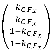
  • The mathematical distribution in vector form is captured by the follow equation: ΔF x , local , cmd , F x F x , global , cmd = k C , F x k C , F x 1 k C , F x 1 k C , F x F x , global , cmd 2
    Figure imgb0001
  • In this equation:
    • ΔFx,local,cmd,Fx (Fx,global,cmd ) is a 4 x 1 command vector in which each vector element represents the local x-direction force command for each of the four control effectors of the aircraft (i.e., the left canard, right canard, left wing, and right wing);
    • k C , F x k C , F x 1 k C , F x 1 k C , F x
      Figure imgb0002
      is 4 x 1 distribution vector comprising the canard weighting factor;
    • Fx,global,cmd is the global x-force command to be distributed to local x-force commands;
    • The factor 1/2 comes from the distribution to two canards/wings.
  • Therefore, taking an example in which the canard weighting factor is selected to be 0.4 (i.e., 40% of the global x-force is provided by the canards, and 60% is provided by wings), the x-direction force command vector ΔFx,local,cmd,Fx (Fx,global,cmd ) will be: 0.2 F x , global , cmd 0.2 F x , global , cmd 0.3 F x , global , cmd 0.3 F x , global , cmd
    Figure imgb0003
    . In other words, each of the two canards provides a 20% contribution of the global force, and each of the two wings provides a 30% contribution to the global force. The total of all four local force contributions is 100% of the global force.
  • The control effectors may be offset from the centre of gravity in the z-direction, and the degree of the offset might change depending on the flap position (which changes with the airspeed). In the example shown in Figure 5b, the control effectors located on the wings are offset from the centre of gravity (CG) by a distance of ΔzW . This offset means that the force contribution provided by the left and right wings also generates a downward pitch moment. In order to counteract this moment, a pitch correction may be introduced. The pitch moment correction command (ΔM cmd,Fx ) may be calculated in accordance with the following equation: ΔM cmd , F x = F x , global , cmd Δz c k C , F x + Δz W 1 k C , F x
    Figure imgb0004
  • The control effectors located on the canards are not offset from the centre of gravity in the z-direction in the example shown in Figures 5a and 5b, but in other examples they may be offset by a distance of Δzc which may either contribute to the pitch coupling generated by the wing control effectors or counteract the pitch coupling (depending on whether Δzc is the same direction or the opposite direction to ΔzW ).
  • Distribution of global z-forces to local z-forces
  • Figure 6 shows an exemplary distribution of global z-forces to local z-forces at each control effector. The distribution of z-forces in this example is determined to prevent generating any moment on the aircraft.
  • To avoid generating a moment on the aircraft, the weighting of distribution of z-forces between the canards and the wings (i.e., the canard weighting factor) cannot be arbitrary, as it can be for the distribution of x-forces. Applying an arbitrary canard weighting first and correcting for moments in a second step (similar to the principle described for the x-force distribution) is less preferable as both global z-forces (to affect the z-movement of the aircraft) and pitch moments are eventually distributed to local z-forces. Typically, the z-force components distributed to the canards are proportionally smaller than the force components distributed to the wings because the position of the centre of gravity is located on the fuselage slightly closer to the wings than to the canards.
  • Similar to the global force commands, global moment commands can be represented as local force contributions. Moments are always generated when local forces are generated by the control effectors at a lever arm from the centre of gravity. The present control method makes use of this relationship. Similar to the distribution of global x-force commands, the breakdown of global z-force commands to local z-force command contributions can be described in a mathematical form. In particular, an equation for distributing the global z-force to local z-forces can be derived as follows.
  • The global z-force acting on the aircraft (Fz,global,cmd ) is given by the sum of the z-forces generated by each of the two canards (i.e., 2 · Fz,local,C ) and by each of the two wings (i.e., 2 · Fz,local,W ). This is set out mathematically equation (I) below: F z , global , cmd = 2 F z , local , C + F z , local , W
    Figure imgb0005
  • In order to avoid generating a residual pitch moment on the aircraft, the sum of the moments generated by the local z-forces generated by the canards and the wings must be zero, as given by equation (II) below: M residual = 0 = 2 F z , local , C Δx C + F z , local , W Δx W
    Figure imgb0006
  • Equation (II) can be rearranged and rewritten as shown in equation (III) below: F z , local , C = F z , local , W Δx W Δx C
    Figure imgb0007
  • Substituting equation (III) into (I) and rearranging provides the following two expressions for the local z-force contributions of each of the canards and wings: F z , local , C = F z , global , cmd 2 Δx W Δx C + Δx W = F z , global , cmd 2 1 1 k F z with k F z = Δx C + Δx W Δx C
    Figure imgb0008
    F z , local , W = F z , global , cmd 2 Δx W Δx C + 1 = F z , global , cmd 2 Δx C Δx C + Δx W = F z , global , cmd 2 k F z with k F z = Δx C + Δx W Δx C
    Figure imgb0009
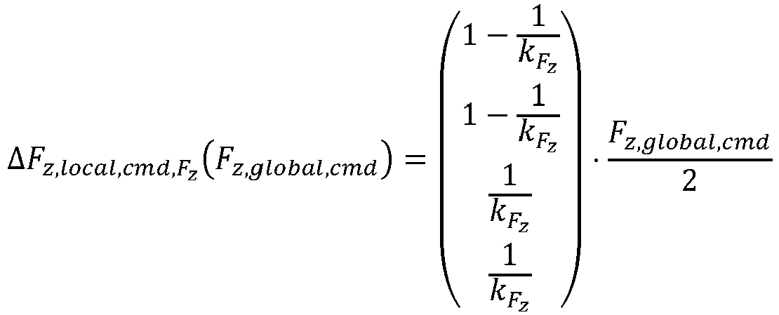
  • Vectorising the above two expressions provides a single equation for distributing z-forces as follows: ΔF z , local , cmd , F z F z , global , cmd = 1 1 k F z 1 1 k F z 1 k F z 1 k F z F z , global , cmd 2
    Figure imgb0010
    ln which : k F z = Δx C + Δx W Δx C
    Figure imgb0011
  • In this equation:
    • ΔFz,local,cmd,Fz (Fz,global,cmd ) is a 4 x 1 command vector in which each vector element represents the local z-direction force command for each of the four control effectors of the aircraft (i.e., the left canard, right canard, left wing, and right wing);
    • 1 1 k F z 1 1 k F z 1 k F z 1 k F z
      Figure imgb0012
      is the 4 x 1 distribution vector comprising the canard weighting factor kFz .
    • Fz,global,cmd is the global z-force command to be distributed to local z-force commands;
    • The factor 1/2 again comes from the distribution to two canards/wings as derived above.
  • In this case is the canard weighting factor k F z = Δx C + Δx W Δx C
    Figure imgb0013
    , or in other words it is the ratio of the sum of the canard and wing lever arms to the canard lever arm. Therefore, the closer centre of gravity to the wings, the smaller ΔxW will be and the canard weighting factor will tend towards 1, meaning that the first and second elements of the distribution vector 1 1 k F z
    Figure imgb0014
    will tend towards 0 and the third and fourth elements of the distribution vector will tend towards 1 thereby producing a command vector that distributes z-forces to the wings more than to the canards. The closer centre of gravity to the canards, the smaller Δxc will be and the canard weighting factor will tend towards a large number, meaning that the first two elements of the distribution vector 1 1 k F z
    Figure imgb0015
    will tend towards 1 and the third and fourth elements of the distribution vector will tend towards 0 thereby producing a command vector that distributes z-forces to the canards more than to the wings.
  • Distribution of roll moment commands to local z-forces
  • Figure 7 shows an exemplary distribution of roll moment commands to local z-forces at each control effector.
  • Similar to the distribution of x-force commands described above, the distribution of a roll moment command to local z-forces is defined as a function of the corresponding canard weighting. The local force commands for the left canard and right canard have the same magnitude, but with different signs. The same holds true for the left and right wings. Both local force commands on the left side of the aircraft (i.e., the left canard and the left wing) have the same sign, but possibly with different magnitudes. The same applies to the right side of the aircraft (i.e., the right canard and right wing).
  • The mathematical expression of the roll moment command distribution to local z-force command contributions is therefore as follows: ΔF z , local , cmd , L L cmd = k C , L Δy C , L k C , L Δy C , L 1 k C , L Δy W , L 1 k C , L Δy W , L L cmd 2
    Figure imgb0016
  • In this equation:
    • ΔFz,local,cmd,L (Lcmd ) is a 4 x 1 command vector in which each vector element represents the local z-direction force command for each of the four control effectors of the aircraft (i.e., the left canard, right canard, left wing, and right wing);
    • k C , L Δy C , L k C , L Δy C , L 1 k C , L Δy W , L 1 k C , L Δy W , L
      Figure imgb0017
      is the 4 x 1 distribution vector comprising the canard weighting factor kC,L and the lever arms ΔyC,L and ΔyW,L for the canard and wing respectively in the y-direction with respect to the centre of gravity;
    • Lcmd is the roll command to be distributed to local z-force commands;
    • The factor 1/2 again comes from the distribution to two canards/wings as derived above.
  • No pitch moment is generated by the local forces, because the pitch moments generated by the left hand side control effectors (left canard and left wing) are cancelled by the pitch moments generated by the right hand side control effectors (right canard and right wing).
  • Distribution of pitch moment commands to local z-forces
  • Figure 8 shows an exemplary distribution of pitch moment commands to local z-forces at each control effector.
  • Pitch moments are distributed to local z-forces on both the canards and the wings. In order not to generate any residual net z-forces on aircraft level, the local z-force commands allocated to canards must be of the same magnitude as the z--force commands allocated to wings, but in the opposite direction (i.e., a different sign). Figure 8 shows an exemplary local z-force distribution resulting from a positive pitch moment command.
  • The breakdown of a pitch moment command to local z-force command contributions can be described in a mathematical form. In particular, an equation for distributing the global z-force to local z-forces can be derived as follows.
  • First, the net z-force acting on the aircraft (Fz,residual ) is given by the sum of the z-forces generated by each of the two canards (i.e., 2 · Fz,local,C ) and by each of the two wings (i.e., 2 · Fz,local,W ). In order to avoid generating a residual z-force on the aircraft, the sum of the local z-forces generated by the canards and the wings must be zero. This is set out mathematically equation (I) below: F z , residual = 0 = 2 F z , local , C + F z , local , W
    Figure imgb0018
  • Second, the pitch moment generated by each of the two canards and the two wings is given by multiplying the force generated by each canard or wing by its lever arm from the centre of gravity (ΔxC and ΔxW respectively). Taking account of the opposite directions (and therefore signs) of the forces, the pitch moment (Mcmd ) can be expressed as follows in equation (II): M cmd = 2 F z , local , C Δx C + F z , local , W Δx W
    Figure imgb0019
  • From equation (I) it can be shown that: F z , local , W = F z , local , C
    Figure imgb0020
  • Substituting equational (III) into equation (II) and rearranging gives: F z , local , C = M cmd 2 k M
    Figure imgb0021
    F z , local , W = M cmd 2 k M
    Figure imgb0022
    where k M = Δx C + Δx W
    Figure imgb0023
  • Vectorising the above expressions provides a single equation for distributing pitch moments to z-forces as follows: ΔF z , local , cmd , M M cmd = 1 k M 1 k M 1 k M 1 k M M cmd 2 where k M = Δx C + Δx W
    Figure imgb0024
  • In this equation:
    • ΔFz,local,cmd,M (Mcmd ) is a 4 x 1 command vector in which each vector element represents the local z-direction force command for each of the four control effectors of the aircraft (i.e., the left canard, right canard, left wing, and right wing);
    • 1 k M 1 k M 1 k M 1 k M
      Figure imgb0025
      is the 4 x 1 distribution vector comprising the canard weighting factor kM which
      comprises the lever arms ΔxC and ΔxW for the canard and wing respectively in the x-direction with respect to the centre of gravity;
    • Mcmd is the pitch command to be distributed to local z-force commands;
    • The factor 1/2 again comes from the distribution to two canards/wings as derived above.
  • In this example, the pitch moment command Mcmd is considered to already include the pitch coupling correction from the global x-force generation (i.e., Mcmd = Mcmd,original + ΔMcmd,Fx ).
  • Distribution of yaw moment commands to local x-forces
  • Figure 9 shows an exemplary distribution of yaw moment commands to local z-forces at each control effector.
  • The yaw moment command distribution is very similar to the distribution of roll moment commands. In contrast however, the moment is distributed to local x-forces rather than local z-forces. Again, both canard contributions have the same magnitude, and so do the wing contributions, but the contributions by the control effectors on the left-hand side are in the opposite direction to the contributions by the control effectors on the right-hand side. Canard and wing contributions for the same side of the aircraft have the same sign.
  • The mathematical expression of the yaw moment command distribution to local x-force command contributions is therefore as follows: ΔF x , local , cmd , N N cmd = k C , N Δy C , N k C , N Δy C , N 1 k C , N Δy W , N 1 k C , N Δy W , N N cmd 2
    Figure imgb0026
  • In this equation:
    • ΔFx,local,cmd,N (Ncmd ) is a 4 x 1 command vector in which each vector element represents the local x-direction force command for each of the four control effectors of the aircraft (i.e., the left canard, right canard, left wing, and right wing);
    • k C , N Δy C , N k C , N Δy C , N 1 k C , N Δy W , N 1 k C , N Δy W , N
      Figure imgb0027
      is the 4 x 1 distribution vector comprising the canard weighting factor kC,N and the lever arms ΔyC,N and ΔyW,N for the canard and wing respectively in the y-direction with respect to the centre of gravity;
    • Ncmd is the yaw command to be distributed to local x-force commands;
    • The factor 1/2 again comes from the distribution to two canards/wings as derived above.
  • No net x-direction force is generated by the local forces, because the x-forces generated by the left hand side control effectors (left canard and left wing) are cancelled by the x-forces generated by the right hand side control effectors (right canard and right wing), resulting in only a yaw moment to rotate the aircraft about the centre of gravity without creating a net x-force to move the aircraft forward in the x-direction.
  • Summation of local force contributions
  • Once all of the global forces and moments have been distributed to local x-forces and z-forces at each control effector (as above), the individual local x-force and z-force command contributions from each global-to-local distribution need to be summed up to determine the total (index t), local force command on each individual control effector. Each local force contribution described above is a 4 x 1 vector where each of the four elements represents one of the two canards and two wings.
  • The summation of the local x-force contributions can be expressed as follows: F x , local , cmd , t = ΔF x , local , cmd , F x F x , global , cmd + ΔF x , local , cmd , N N cmd
    Figure imgb0028
  • The total x-force command therefore includes two components: the total global x-force commands (Fx,local,cmd,Fx ) and yaw moment commands (Fx,local,cmd,N ).
  • The summation of the local z-force contributions can be expressed as follows: F zlocal , cmd , t = ΔF z , local , cmd , F z F z , global , cmd + ΔF z , local , cmd , L L cmd + ΔF z , local , cmd , M M cmd
    Figure imgb0029
  • The total z-force command therefore includes three components: the total global z-force commands (Fz,local,cmd,Fz ), the roll moment commands (ΔFz,local,cmd,L ) and the pitch moment commands (Fz,local,cmd,M ).
  • Resultantly, there are now four individual control allocation problems that need to be solved - one for each canard and wing - rather than a more complex single global control allocation problem. The problems are solved by finding parameters of the control effectors which, according to an aircraft simulation model, generate the required combination of local x-forces and local z-forces. In the examples described herein, the control effects are propulsion engines mounted in adjustable flaps. Accordingly, the parameters of the control effectors include: (a) a flap angle and (b) an engine power (essentially, engine rotor speed). In case of another aircraft configuration, different control effectors may be used having different adjustable parameters for generating forces.
  • For simplicity, in some cases each canard and each wing may apply the same flap angle command and rotor speed command to all the flaps and engines within that wing/canard. As a consequence, the local force problem is deterministic and is solved by finding a combination of two actuator states (i.e. one flap angle state and one rotor speed state) that generate a combination of the required local x-forces and local z-forces.
  • In other cases, the flap angle or rotor speed commands may be different for different engines within the wing/canard. For example, the thrust (i.e., rotor speed) of at least one of the propulsion engines within a wing/canard may be adjusted depending, at least in part, on the distance between that engine and the centre of mass of the aircraft. In this example, the moment can be increased by increasing the rotor speeds of engines located furthest from the centre of mass.
  • Figure 10 shows a flow diagram of the steps of the method described herein.
  • In a first step, a global force and/or moment allocation required to control movement of an aircraft is determined. The global force and/or moment allocation relates to a net force and/or moment to act on the aircraft. For example, if it is required that the aircraft moves forward and upward, the global force relates to the net x-force required to move the aircraft forward by the desired amount and the net z-force to move the aircraft upward by the desired amount.
  • In a second step, a local force and/or moment allocation is determined. The local force and/or moment allocation relates to the force and/or moment contribution to the net force provided by at least one of the control effectors. Thus, the local force and/or moment allocation represents the individual local force contributions provided by each control effector. The global x-forces and z-forces are broken down into individual local x-force and z-force contributions as described above in the sections headed "Distribution of global x-forces to local x-forces" and "Distribution of global z-forces to local z-forces". The moments are broken down into individual local x-force and z-force contributions as described above in the sections headed "Distribution of roll moment commands to local z-forces", "Distribution of pitch moment commands to local z-forces" and "Distribution of yaw moment commands to local z-forces".
  • In a third step, the local x-force and z-force contributions from each control effector are summed to provide the total force contributions required from each control effector to provide the global forces and moments required in the first step. As a result of this summation, there are four control allocation problems (one for each of the canards and wings) which must be solved.
  • In a fourth step, the control allocation problems are solved to determine control effector parameters that generate the required combination of local x-forces and local z-forces. As described above, these parameters may be a flap angle for each of the canards and wings, and a rotor speed for the engines located in the flaps, which will generate the x-forces and z-forces required at each canard/wing.
  • In a fifth step, the control effectors are actuated according to the determined parameters to generate the determined local forces and/or moments. For example, the flap is adjusted to the determined flap angle, and the engine rotor speed is adjusted to the determined level.
  • While the invention has been described above with reference to a VTOL aircraft, the concepts can also be applied to other aircraft configurations. For example, the concepts may be applied to aircraft with means to generate lateral forces (in the y-direction) directly through appropriate control devices.
  • It will be understood that the invention has been described above purely by way of example, and modifications of detail can be made within the scope of the invention.
  • Each feature disclosed in the description, and (where appropriate) the claims and drawings may be provided independently or in any appropriate combination.
  • Reference numerals appearing in the claims are by way of illustration only and shall have no limiting effect on the scope of the claims.
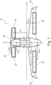
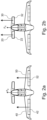
Claims (15)

  1. A computer implemented method for controlling an aircraft (10), the aircraft having multiple control effectors (22, 32, 42, 52), the method comprising:
    determining a global force and/or moment allocation required to control movement of the aircraft (10), the global force and/or moment allocation relating to a net force and/or moment to act on the aircraft (10);
    determining a local force and/or moment allocation, the local force and/or moment allocation relating to a force and/or moment contribution to the net force provided by at least one of the control effectors (22, 32, 42, 52); and
    controlling at least one of the control effectors (22, 32, 42, 52) to generate the determined local force and/or moment.
  2. A method according to Claim 1, comprising determining at least two local force and/or moment allocations relating to force and/or moment contributions to the net force provided by at least two control effectors (22, 32, 42, 52).
  3. A method according to Claim 2, wherein each of the at least two local force and/or moment allocations corresponds to a different degree of freedom of the aircraft (10).
  4. A method according to any preceding claim, wherein controlling the at least one of the control effectors (22, 32, 42, 52) comprises adjusting at least one parameter of the control effectors to generate the local force and/or moment.
  5. A method according to Claim 4, wherein the at least one parameter is adjusted based, at least in part, on at least one condition external to the aircraft (10).
  6. A method according to any preceding claim, wherein the local force and/or moment allocation is determined based, at least in part, on at least one condition external to the aircraft (10).
  7. A method according to any preceding claim, wherein the local force and/or moment allocation for one control effector (22, 32, 42, 52) is determined, at least in part, to compensate for a force and/or moment generated by another control effector.
  8. A method according to any preceding claim, wherein the at least one control effector (22, 32, 42, 52) comprises at least one propulsion engine.
  9. A method according to Claim 8, wherein the propulsion engine is an electric propulsion engine with a ducted fan.
  10. A method according to Claim 8 or 9, wherein controlling the at least one of the control effectors (22, 32, 42, 52) comprises adjusting a thrust of the at least one propulsion engine.
  11. A method according to Claim 10, wherein the control effectors (22, 32, 42, 52) comprise multiple propulsion engines, and wherein the thrust of at least one of the propulsion engines is adjusted based, at least in part, on the distance between that propulsion engine and the centre of mass of the aircraft (10).
  12. A method according to any preceding claim, wherein the at least one control effector (22, 32, 42, 52) comprises at least one control surface, preferably wherein controlling the at least one of the control effectors comprises adjusting an angle of the at least one control surface.
  13. A method according to Claim 12, wherein the at least one control effector (22, 32, 42, 52) comprises at least one engine mounted at or near the control surface, the position of the engine being movable with the control surface for variation of a thrust vector.
  14. A method according to any preceding claim, wherein the control effectors (22, 32, 42, 52) are located on wings (40, 50) and/or on canards (20, 30) of the aircraft (10).
  15. An aircraft (10) comprising a processor and memory storing computer code which, when executed on the processor, performs the method of any preceding claim.
EP23190611.6A 2023-08-09 2023-08-09 Aircraft control Pending EP4506770A1 (en)

Priority Applications (5)

Application Number Priority Date Filing Date Title
EP23190611.6A EP4506770A1 (en) 2023-08-09 2023-08-09 Aircraft control
PCT/EP2024/068618 WO2025031676A1 (en) 2023-08-09 2024-07-02 Aircraft control
CN202480052329.4A CN121666562A (en) 2023-08-09 2024-07-02 Aircraft control
KR1020267007255A KR20260049636A (en) 2023-08-09 2024-07-02 Aircraft control
AU2024321319A AU2024321319A1 (en) 2023-08-09 2024-07-02 Aircraft control

Applications Claiming Priority (1)

Application Number Priority Date Filing Date Title
EP23190611.6A EP4506770A1 (en) 2023-08-09 2023-08-09 Aircraft control

Publications (1)

Publication Number Publication Date
EP4506770A1 true EP4506770A1 (en) 2025-02-12

Family

ID=87567469

Family Applications (1)

Application Number Title Priority Date Filing Date
EP23190611.6A Pending EP4506770A1 (en) 2023-08-09 2023-08-09 Aircraft control

Country Status (5)

Country Link
EP (1) EP4506770A1 (en)
KR (1) KR20260049636A (en)
CN (1) CN121666562A (en)
AU (1) AU2024321319A1 (en)
WO (1) WO2025031676A1 (en)

Citations (2)

* Cited by examiner, † Cited by third party
Publication number Priority date Publication date Assignee Title
US20220126995A1 (en) * 2020-05-13 2022-04-28 Dalian University Of Technology Coaxial tilt-rotor unmanned aerial vehicle and control method thereof
US20220376514A1 (en) * 2021-05-19 2022-11-24 Lilium Eaircraft Gmbh Time variable electrical load sharing in a power distribution network of an aircraft

Patent Citations (2)

* Cited by examiner, † Cited by third party
Publication number Priority date Publication date Assignee Title
US20220126995A1 (en) * 2020-05-13 2022-04-28 Dalian University Of Technology Coaxial tilt-rotor unmanned aerial vehicle and control method thereof
US20220376514A1 (en) * 2021-05-19 2022-11-24 Lilium Eaircraft Gmbh Time variable electrical load sharing in a power distribution network of an aircraft

Also Published As

Publication number Publication date
KR20260049636A (en) 2026-04-14
WO2025031676A1 (en) 2025-02-13
CN121666562A (en) 2026-03-13
AU2024321319A1 (en) 2026-02-26

Similar Documents

Publication Publication Date Title
Schmollgruber et al. Multidisciplinary exploration of DRAGON: an ONERA hybrid electric distributed propulsion concept
Blight et al. Practical control law design for aircraft using multivariable techniques
Bourdin et al. The application of variable cant angle winglets for morphing aircraft control
Cobleigh Development of the X-33 aerodynamic uncertainty model
van Ginneken et al. Automated control surface design and sizing for the prandtl plane
Liguo et al. Effective control allocation using hierarchical multi-objective optimization for multi-phase flight
Eberhardt et al. Indirect adaptive flight control of a tailless fighter aircraft
Dogan et al. Control and simulation of relative motion for aerial refueling in racetrack maneuvers
Datta Fundamental understanding, prediction and validation of rotor vibratory loads in steady-level flight
Montgomery et al. A methodology for roll control of morphing aircraft
Wahid et al. Comparative assesment using LQR and fuzzy logic controller for a pitch control system
Wu et al. Reinforcement Learning Approach to Flight Control Allocation with Distributed Electric Propulsion
Wise Applied controls research topics in the aerospace industry
AU2024321319A1 (en) Aircraft control
Bieniawski et al. Flight control with distributed effectors
Garmendia A multi-disciplinary conceptual design methodology for assessing control authority on a hybrid wing body configuration
Van Lateral stability and control of an aircraft equipped with a small vertical tail by differential use of the propulsion systems. Use of co-design methods
Baggi et al. Dynamic control allocation for a class of over-actuated aircraft
Sarafraz et al. Effects of rotor inflow models on dynamic responses of variable-pitch quadrotors: Y. Sarafraz, F. Shahmiri
Basson Control allocation as part of a fault-tolerant control architecture for UAVs
Antonakis Handling Qualities sizing for aerial vehicles based on control moment polytopes
Pankonien et al. Deadbands Tell No Tails: X-56A Dynamic Actuation Requirements
Ganguli et al. Optimal location of centre of gravity for swashplateless helicopter UAV and MAV
CN115686037B (en) A control method and system for a variable attitude aircraft
Enenakpogbe Integrated NDI-based Controller and Incremental Control Allocation for an eVTOL

Legal Events

Date Code Title Description
PUAI Public reference made under article 153(3) epc to a published international application that has entered the european phase

Free format text: ORIGINAL CODE: 0009012

STAA Information on the status of an ep patent application or granted ep patent

Free format text: STATUS: THE APPLICATION HAS BEEN PUBLISHED

AK Designated contracting states

Kind code of ref document: A1

Designated state(s): AL AT BE BG CH CY CZ DE DK EE ES FI FR GB GR HR HU IE IS IT LI LT LU LV MC ME MK MT NL NO PL PT RO RS SE SI SK SM TR

19U Interruption of proceedings before grant

Effective date: 20250313

19W Proceedings resumed before grant after interruption of proceedings

Effective date: 20260401