EP4506733A1 - Radiation detection device, radiation detection system, and radiation detection method - Google Patents
Radiation detection device, radiation detection system, and radiation detection method Download PDFInfo
- Publication number
- EP4506733A1 EP4506733A1 EP23811363.3A EP23811363A EP4506733A1 EP 4506733 A1 EP4506733 A1 EP 4506733A1 EP 23811363 A EP23811363 A EP 23811363A EP 4506733 A1 EP4506733 A1 EP 4506733A1
- Authority
- EP
- European Patent Office
- Prior art keywords
- target object
- ray
- radiation
- reset operation
- detection element
- Prior art date
- Legal status (The legal status is an assumption and is not a legal conclusion. Google has not performed a legal analysis and makes no representation as to the accuracy of the status listed.)
- Pending
Links
Images







Classifications
-
- G—PHYSICS
- G01—MEASURING; TESTING
- G01N—INVESTIGATING OR ANALYSING MATERIALS BY DETERMINING THEIR CHEMICAL OR PHYSICAL PROPERTIES
- G01N23/00—Investigating or analysing materials by the use of wave or particle radiation, e.g. X-rays or neutrons, not covered by groups G01N3/00 – G01N17/00, G01N21/00 or G01N22/00
- G01N23/02—Investigating or analysing materials by the use of wave or particle radiation, e.g. X-rays or neutrons, not covered by groups G01N3/00 – G01N17/00, G01N21/00 or G01N22/00 by transmitting the radiation through the material
- G01N23/04—Investigating or analysing materials by the use of wave or particle radiation, e.g. X-rays or neutrons, not covered by groups G01N3/00 – G01N17/00, G01N21/00 or G01N22/00 by transmitting the radiation through the material and forming images of the material
-
- G—PHYSICS
- G01—MEASURING; TESTING
- G01T—MEASUREMENT OF NUCLEAR OR X-RADIATION
- G01T1/00—Measuring X-radiation, gamma radiation, corpuscular radiation, or cosmic radiation
- G01T1/16—Measuring radiation intensity
- G01T1/24—Measuring radiation intensity with semiconductor detectors
-
- G—PHYSICS
- G01—MEASURING; TESTING
- G01N—INVESTIGATING OR ANALYSING MATERIALS BY DETERMINING THEIR CHEMICAL OR PHYSICAL PROPERTIES
- G01N2223/00—Investigating materials by wave or particle radiation
- G01N2223/30—Accessories, mechanical or electrical features
- G01N2223/306—Accessories, mechanical or electrical features computer control
-
- G—PHYSICS
- G01—MEASURING; TESTING
- G01V—GEOPHYSICS; GRAVITATIONAL MEASUREMENTS; DETECTING MASSES OR OBJECTS; TAGS
- G01V5/00—Prospecting or detecting by the use of ionising radiation, e.g. of natural or induced radioactivity
- G01V5/20—Detecting prohibited goods, e.g. weapons, explosives, hazardous substances, contraband or smuggled objects
- G01V5/22—Active interrogation, i.e. by irradiating objects or goods using external radiation sources, e.g. using gamma rays or cosmic rays
Definitions
- One aspect of the present invention relates to a radiation detection apparatus, a radiation detection system, and a radiation detection method.
- a radiation detection apparatus that detects radiation transmitted through a target object.
- the radiation transmitted through the target object is directly converted into an electric charge by a direct conversion material of a detection element, and the electric charge is collected by a pixel electrode, whereby the radiation is detected and a radiation captured image is obtained.
- a polarization phenomenon polarization
- the detection element is continuously irradiated with the radiation, a polarization phenomenon (polarization) occurs in the detection element, and the radiation captured image may deteriorate. Therefore, it is required to eliminate the polarization phenomenon in the detection element.
- the polarization phenomenon in the radiation detection apparatus is eliminated by turning on/off a high voltage (HV) supplied from a HV power supply apparatus to the radiation detection apparatus at a predetermined cycle.
- HV high voltage
- a bias voltage is applied such that stop periods of bias application to the respective radiation detection apparatuses do not overlap each other, thereby suppressing simultaneous occurrence of the polarization phenomenon in the plurality of radiation detection apparatuses.
- the application of the bias voltage is stopped without considering a situation outside the radiation detection apparatus in order to eliminate the polarization phenomenon in the radiation detection apparatus. Therefore, in a case where a timing at which the polarization phenomenon in the detection element is eliminated in the radiation detection apparatus overlaps a timing at which the radiation incident on the radiation detection apparatus is transmitted through the target object, there is a possibility that the radiation detection apparatus cannot detect the radiation transmitted through the target object.
- One aspect of the present invention has been made in view of the above circumstances, and relates to a radiation detection apparatus, a radiation detection system, and a radiation detection method capable of suppressing occurrence of a polarization phenomenon in a detection element and more reliably detecting radiation incident on the radiation detection apparatus when the radiation is transmitted through a target object.
- the occurrence of the polarization phenomenon in the detection element can be suppressed and radiation incident on the radiation detection apparatus can be more reliably detected when the radiation is transmitted through a target object.
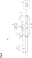
- FIG. 1 is a configuration diagram of an X-ray inspection apparatus 1A which is a radiation detection system according to the present embodiment.
- the X-ray inspection apparatus 1A is an apparatus that irradiates an inspection target object (target object) F conveyed in a conveyance direction TD with an X-ray (radiation) and acquires an X-ray image (captured image) obtained by imaging the inspection target object F based on the X-ray transmitted through the inspection target object F.
- the X-ray inspection apparatus 1A performs foreign matter inspection, weight inspection, product inspection, and the like targeting on the inspection target object F by using the X-ray image.
- the X-ray inspection apparatus 1A includes a conveyance unit (conveyance apparatus) 2 that conveys the inspection target object F, an X-ray generator (light source) 3 that emits the X-ray, an X-ray detection camera 100, a light source 7, a target object sensor 8, a control apparatus 4, and a shielding portion 5 that blocks the X-ray.
- a conveyance unit conveys the inspection target object F
- an X-ray generator (light source) 3 that emits the X-ray
- an X-ray detection camera 100 a light source 7, a target object sensor 8, a control apparatus 4, and a shielding portion 5 that blocks the X-ray.
- the radiation in the present invention is not limited to the X-ray, and includes radiation other than the X-ray, such as a ⁇ -ray. In the present embodiment, description will be made assuming that the radiation is the X-ray.
- the conveyance unit 2 conveys the inspection target object F such that the inspection target object F passes through an irradiation region R3 irradiated with the X-ray by the X-ray generator 3.
- the conveyance unit 2 includes a belt 2a on which the inspection target object F is placed. In the conveyance unit 2, the belt 2a moves in the conveyance direction TD, so that the inspection target object F is conveyed in the conveyance direction TD at a predetermined conveyance speed. A plurality of inspection target objects F are placed on the belt 2a at predetermined intervals. Each inspection target object F is sequentially conveyed to the irradiation region R3 as the belt 2a moves.
- examples of the inspection target object F conveyed by the conveyance unit 2 include various articles including food such as meat, fish and shellfish, agricultural products, and confectionery, rubber products such as tires, resin products, metal products, resource materials such as minerals, wastes, electronic components, and electronic substrates.
- the X-ray generator 3 is an apparatus that irradiates the inspection target object F with the X-ray (outputs the X-ray) as an X-ray source.
- the X-ray generator 3 is, for example, a point light source, and diffuses and emits the X-ray in a constant irradiation direction (a predetermined angular range).
- the X-ray generator 3 is provided such that the irradiation direction is on a conveyance unit 2 side.
- the X-ray generator 3 is provided above the conveyance unit 2 so as to be separated from the conveyance unit 2 by a predetermined distance.
- the X-ray generator 3 is provided such that the X-ray irradiation region R3 extends over the entire width direction (a direction intersecting the conveyance direction TD) of the inspection target object F.
- the X-ray generator 3 sets a predetermined division range in a length direction as the irradiation region R3 in the length direction (the conveyance direction TD) of the inspection target object F.
- the inspection target object F is conveyed by the conveyance unit 2, and the entire inspection target object F passes through the irradiation region R3 of the X-ray generator 3, so that the inspection target object F is irradiated with the X-ray over the entire length direction.
- a tube voltage and a tube current are set by the control apparatus 4.
- the X-ray generator 3 irradiates the conveyance unit 2 with the X-ray having predetermined energy and radiation dose according to the set tube voltage and tube current.
- the X-ray detection camera 100 detects the X-ray transmitted through at least the conveyance unit 2 among the X-rays emitted toward the conveyance unit 2 by the X-ray generator 3, and outputs the X-ray image based on the X-ray.
- the X-ray detection camera (radiation detection apparatus) 100 is, for example, an X-ray flat panel sensor or an X-ray line sensor camera, and includes a radiation detection unit (detection element) 20x (see FIG. 2 ) including at least one row of pixel lines in which a plurality of pixels are arranged in a pixel arrangement direction.
- the radiation detection unit 20x is a direct conversion type radiation detection element that directly converts an incident X-ray into an electric charge.
- the X-ray detection camera 100 generates the X-ray image based on the detected X-ray, and outputs the generated X-ray image to the control apparatus 4.
- the radiation detection unit 20x of the X-ray detection camera 100 may be a one-dimensional sensor (single-line sensor) in which one pixel line is provided, or may be a two-dimensional sensor including a plurality of pixel lines.
- the two-dimensional sensor may be an area scanning type two-dimensional sensor.
- a line scanning type two-dimensional sensor such as a multi-line sensor including a plurality of pixel lines or a time delay integration (TDI) sensor may be used.
- TDI time delay integration
- the light source 7 irradiates the inspection target object F with light for target object sensing (outputs the light for target object sensing). It is sufficient if the light source 7 outputs light that can be sensed by the target object sensor 8, and may output visible light, infrared light, or the X-ray, for example.
- the light source 7 is provided above the conveyance unit 2, for example. Note that, in the present embodiment, the target object sensor 8 senses the light output from the light source 7 and transmitted through the inspection target object F, and thus, the light source 7 is provided on an opposite side of the inspection target object F from the target object sensor 8 (that is, above the conveyance unit 2).
- the light source 7 may be provided below the conveyance unit 2 similarly to the target object sensor 8.
- the light source 7 and the target object sensor 8 are not limited to be installed in a vertical direction, and may be installed in a horizontal direction.
- the light source 7 and the target object sensor 8 may be installed in the width direction (a direction intersecting the conveyance direction TD) of the inspection target object F, in the length direction (the conveyance direction TD) of the inspection target object F, or in an oblique direction including the width direction and the length direction.
- a member that reflects light such as a mirror, may be provided between the light source 7 and the target object sensor 8.
- the light source 7 and the target object sensor 8 may be integrated with each other.
- the target object sensor 8 is a sensor that senses the inspection target object F.
- the target object sensor 8 senses the inspection target object F by sensing the light output from the light source 7. In the present embodiment, it is described that the target object sensor 8 senses the light transmitted through the inspection target object F, but the target object sensor 8 may sense light reflected by the inspection target object F. A specific configuration example of the target object sensor 8 is described below.
- the control apparatus 4 is, for example, a computer such as a personal computer (PC).
- the control apparatus 4 is electrically connected to the X-ray detection camera 100.
- the control apparatus 4 controls the X-ray detection camera 100 to repeatedly perform imaging at a predetermined detection cycle.
- the control apparatus 4 sets the predetermined detection cycle such that each of the plurality of pixel lines can image the X-ray transmitted through the same region of the inspection target object F.
- the control apparatus 4 generates an X-ray image based on the X-ray image output from the X-ray detection camera 100.
- control apparatus 4 generates one X-ray image by connecting image data of one line output from the X-ray detection camera 100.
- the control apparatus 4 may generate one X-ray image by executing averaging processing or addition processing on the data output from the X-ray detection camera 100.
- control apparatus 4 may be an apparatus independently provided outside the X-ray detection camera 100 or may be integrated inside the X-ray detection camera 100.
- the predetermined detection cycle may be set based on, for example, at least one of a distance between the plurality of pixel lines of the radiation detection unit 20x, a distance between the X-ray generator 3 and the inspection target object F on the conveyance unit 2 (focus object distance (FOD)), or a distance between the X-ray generator 3 and the radiation detection unit 20x (focus detector distance (FDD)).
- the predetermined detection cycle may be individually set based on a pixel width in a direction orthogonal to the pixel arrangement direction of the pixels constituting the pixel line of the radiation detection unit 20x.
- a deviation (delay time) of the detection cycle between the plurality of pixel lines may be specified according to the distance between the plurality of pixel lines, the conveyance speed of the conveyance unit 2, the distance (FOD) between the X-ray generator 3 and the inspection target object F on the conveyance unit 2, and the distance (FDD) between the X-ray generator 3 and the radiation detection unit 20x, and the individual cycles may be respectively set.
- the shielding portion 5 prevents the X-ray emitted from the X-ray generator 3 from leaking to the outside of the X-ray inspection apparatus 1A.
- the shielding portion 5 is provided so as to surround the periphery of the irradiation region R3 of the X-ray generator 3.
- the shielding portion 5 has a carry-in port 5a and a carry-out port 5b through which the conveyance unit 2 and the inspection target object F conveyed by the conveyance unit 2 pass.
- the carry-in port 5a is formed upstream of the irradiation region R3 of the X-ray generator 3 in the conveyance unit 2.
- the carry-out port 5b is formed downstream of the irradiation region R3 of the X-ray generator 3 in the conveyance unit 2.
- the inspection target object F conveyed by the conveyance unit 2 passes through the carry-in port 5a, the irradiation region R3 of the X-ray generator 3, and the carry-out port 5b in this order.
- a shielding curtain 5c is provided between the irradiation region R3 and regions of the carry-in port 5a and the carry-out port 5b so as to partition the irradiation region R3 and the regions of the carry-in port 5a and the carry-out port 5b, and suppresses the X-ray from leaking to the outside of the X-ray inspection apparatus 1A.
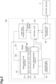
- FIG. 2 is a configuration diagram of the X-ray detection camera 100.
- the X-ray detection camera 100 includes a detection unit 20, a first bias power supply 30 (voltage source), a second bias power supply 40, a control unit 50, and an input/output interface 60.
- the detection unit 20 includes the radiation detection unit 20x which is a detection element that directly converts the incident X-ray into the electric charge and outputs a result of collecting the electric charge for each of a plurality of pixel electrodes as X-ray image data (captured image data).
- the detection unit 20 continuously outputs the X-ray image data.
- the detection unit 20 is operated by the control unit 50 based on a reference clock (described below).
- the detection unit 20 includes a semiconductor crystal 21, a signal processing circuit 22, a first electrode 23, a plurality of second electrodes 24, and a plurality of third electrodes 25.
- a direction in which the semiconductor crystal 21 and the signal processing circuit 22 extend is referred to as an X direction
- a direction in which the semiconductor crystal 21 and the signal processing circuit 22 are arranged is referred to as a Y direction.
- the first electrode 23 is a bias electrode provided on a surface of the semiconductor crystal 21 on a side opposite to a side facing the signal processing circuit 22.
- the first electrode 23 extends in the X direction which is the pixel arrangement direction, and is integrally configured without being divided.
- the plurality of second electrodes 24 are pixel electrodes provided on a surface of the semiconductor crystal 21 on the side facing the signal processing circuit 22 except for some second electrodes 24 (described below).
- the plurality of second electrodes 24 are arranged in the X direction.
- the plurality of third electrodes 25 are pixel electrodes provided on a surface of the signal processing circuit 22 on a side facing the semiconductor crystal 21.
- the plurality of third electrodes 25 are arranged in the X direction.
- Each of the third electrodes 25 corresponds to each of the second electrodes 24 (each of the third electrodes 25 and each of the second electrodes 24 are arranged to face each other in the Y direction), and is electrically connected to the corresponding second electrode 24.
- the semiconductor crystal 21 is a semiconductor crystal that directly converts the incident X-ray into the electric charge.
- the semiconductor crystal 21 is implemented by, for example, a semiconductor crystal such as cadmium telluride (Cadotel) (CdTe), zinc cadmium telluride (CdZnTe), or thallium bromide (TIBr).
- Cadotel cadmium telluride
- CdZnTe zinc cadmium telluride
- TIBr thallium bromide
- the signal processing circuit 22 is, for example, an application specific integrated circuit (ASIC).
- the signal processing circuit 22 is electrically connected to the second electrode 24 via the third electrode 25.
- the signal processing circuit 22 is a circuit that reads an electric signal between the first electrode 23 and the second electrode 24, and generates the X-ray image data (captured image data) based on the read electric signal.
- the signal processing circuit 22 collects the electric charge for each of the plurality of third electrodes 25, and outputs the collected result to the control unit 50 as the X-ray image data.
- the signal processing circuit 22 continuously outputs the X-ray image data to the control unit 50.
- the X-ray image data includes a digital signal obtained by converting a voltage signal detected by the signal processing circuit 22.
- the X-ray image data may be the X-ray image itself or information for generating the X-ray image.
- the first bias power supply 30 applies the bias voltage to the radiation detection unit 20x of the detection unit 20.
- the first bias power supply 30 is electrically connected to the first electrode 23.
- the first bias power supply 30 applies the bias voltage to the semiconductor crystal 21 via the first electrode 23 according to a control signal from the control unit 50.
- the first bias power supply 30 applies, for example, a high voltage (HV) to the semiconductor crystal 21.
- the first bias power supply 30 is configured to execute a reset operation (described below) on the semiconductor crystal 21.
- the second bias power supply 40 is electrically connected to the signal processing circuit 22 and provides power for operating the signal processing circuit 22.
- the second bias power supply 40 may be a reference potential when the first bias power supply 30 applies the bias voltage.
- the second bias power supply 40 is electrically connected to a photodiode 90 (described below) of a sensing unit 20y, and may provide power for operating the photodiode 90.
- the bias voltage (ON voltage value) to be applied to the radiation detection unit 20x of the detection unit 20 by the first bias power supply 30 may be arbitrarily set, and is, for example, -1000 V.
- the control unit 50 is electrically connected to the signal processing circuit 22 and the first bias power supply 30.
- the control unit 50 is implemented by, for example, a field-programmable gate array (FPGA).
- the control unit 50 controls the detection unit 20 by controlling the signal processing circuit 22 and the first bias power supply 30 based on the reference clock input from the outside of the X-ray detection camera 100.
- the control unit 50 may control the detection unit 20 by controlling the signal processing circuit 22 and the first bias power supply 30 based on the reference clock generated in the X-ray detection camera 100. According to any of these, the control unit 50 outputs a control signal for operating the signal processing circuit 22 to the signal processing circuit 22.
- the control unit 50 acquires the X-ray image data output from the signal processing circuit 22, and outputs the X-ray image data to the outside of the X-ray detection camera 100. For example, the control unit 50 outputs the X-ray image to the control apparatus 4 via the input/output interface 60. The control unit 50 outputs the control signal for operating the first bias power supply 30 to the first bias power supply 30. Furthermore, the control unit 50 may acquire a control signal from the control apparatus 4 via the input/output interface 60. Note that in a case where the X-ray image data is the information for generating the X-ray image, the control unit 50 may generate the X-ray image based on the acquired X-ray image data.
- some of the plurality of second electrodes 24 described above is connected not to the semiconductor crystal 21 but to another photodetector (here, the photodiode 90 as an example).
- the photodiode 90 detects the light emitted from the light source 7.
- the second electrode 24 connected to the photodiode 90 is electrically connected to the signal processing circuit 22 via the third electrode 25.
- the signal processing circuit 22 outputs a signal corresponding to a detection result of the photodiode 90 to the control unit 50 based on the read electric signal.
- Such components related to the output of the detection result of the photodiode 90 function as the sensing unit 20y related to sensing of the inspection target object F.
- a case where the inspection target object F is sensed by the sensing unit 20y is a case where the inspection target object F is present in the irradiation region R3 of the X-ray generator 3.
- the sensing unit 20y is an example of the target object sensor 8 described above. In this case, the target object sensor 8 is provided on the same substrate as the detection unit 20.
- a component related to the generation of the X-ray image data is the radiation detection unit 20x
- a component related to the sensing of the inspection target object F is the sensing unit 20y.
- the radiation detection unit 20x and the sensing unit 20y may or do not have to have sensitivity in the same wavelength/energy band.
- the light (signal) detected by the radiation detection unit 20x may be a reflected image or a transmitted image.
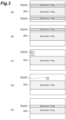
- FIG. 3 is a diagram illustrating a configuration example of the radiation detection unit 20x and the sensing unit 20y (the target object sensor 8), and is plan views of the radiation detection unit 20x and the sensing unit 20y.
- the vertical direction is the conveyance direction of the inspection target object F.
- the sensing units 20y may be provided line by line so as to sandwich the radiation detection unit 20x in the conveyance direction. In this case, for example, the sensing units 20y that sense the inspection target object F can be provided for both forward conveyance and reverse conveyance of the inspection target object F.
- one sensing unit 20y may be provided on only one side of the radiation detection unit 20x in the conveyance direction. Furthermore, as illustrated in FIG. 3(c) , the sensing unit 20y may be provided for one pixel instead of one line.
- the sensing unit 20y may be provided in a plurality of stages and be capable of TDI addition as a countermeasure for a low-dose condition.
- a position of the sensing unit 20y may be an end portion as illustrated in FIG. 3(c) , may be a central portion as illustrated in FIG. 3(d) , or may be any region.
- the sensing unit 20y may be adjacent to the radiation detection unit 20x or may be separated from the radiation detection unit 20x. Further, a part of the radiation detection unit 20x may also serve as the sensing unit 20y as illustrated in FIG. 3(e) .
- the configuration of the target object sensor 8 is not limited to the example of the sensing unit 20y described above.
- the target object sensor 8 may be implemented not by the pixel (the sensing unit 20y) in the detection unit 20 as described above but by a sensor 80 which is a sensor different from the detection unit 20.
- the sensor 80 is a sensor that detects the light emitted from the light source 7, and may be, for example, a camera equipped with a photoelectric sensor such as a photodiode.
- the sensor 80 may or does not have to have sensitivity in the same wavelength/energy band as the detection unit 20 (imaging sensor) related to the generation of the X-ray image data.
- the light (signal) detected by the sensor 80 may be a reflected image or a transmitted image.
- FIG. 4 is a diagram illustrating a configuration example of the detection unit 20 and the sensor 80, which are imaging sensors, and is plan views of the detection unit 20 and the sensor 80.
- the detection unit 20 is illustrated as an "imaging sensor”.
- the vertical direction is the conveyance direction of the inspection target object F.
- the sensors 80 may be provided line by line so as to sandwich the detection unit 20 in the conveyance direction. In this case, for example, the sensor 80 that senses the inspection target object F can be provided for both the forward conveyance and the reverse conveyance of the inspection target object F.
- one sensor 80 may be provided on only one side of the detection unit 20 in the conveyance direction. As illustrated in FIG. 4(c) , the sensor 80 may be provided for one pixel instead of one line. The sensor 80 may be provided in a plurality of stages and be capable of TDI addition as a countermeasure for a low-dose condition. In addition, a position of the sensor 80 may be an end portion as illustrated in FIG. 4(c) , may be a central portion as illustrated in FIG. 4(d) , or may be any region.
- the target object sensor 8 will be described as being implemented by the sensing unit 20y as illustrated in FIG. 2 .
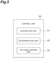
- FIG. 5 is a block diagram illustrating a functional configuration of the control unit 50.
- the control unit 50 includes an acquisition unit 51, a determination unit 52, and a voltage control unit 53.
- the control unit 50 determines the presence or absence of the inspection target object F and controls application of the high voltage (HV) by the first bias power supply 30 according to the determination result.
- HV high voltage
- the acquisition unit 51 acquires the control signal for controlling imaging in the X-ray detection camera 100 from the control apparatus 4.
- the acquisition unit 51 may acquire the control signal generated by the control unit 50 based on the reference clock generated in the X-ray detection camera 100.
- the acquisition unit 51 outputs the acquired control signal to the signal processing circuit 22 or the first bias power supply 30.
- the acquisition unit 51 acquires the X-ray image data from the signal processing circuit 22.
- the acquisition unit 51 outputs the X-ray image to the control apparatus 4.
- the acquisition unit 51 acquires a signal from the sensing unit 20y implementing the target object sensor 8 via the signal processing circuit 22.
- the signal is a signal corresponding to the detection result of the photodiode 90, and is a signal related to the sensing of the inspection target object F.
- the acquisition unit 51 outputs the signal from the sensing unit 20y to the determination unit 52.
- the determination unit 52 executes predetermined determination processing based on the signal acquired by the acquisition unit 51 from the sensing unit 20y (the signal from the target object sensor 8 that senses the inspection target object F irradiated with the X-ray).
- the determination processing here is processing of determining whether or not the reset operation is executable.
- the reset operation is an operation for eliminating a change in an internal electric field, which is a polarization phenomenon (polarization) occurring inside the semiconductor crystal 21 when the semiconductor crystal 21 is continuously irradiated with the X-ray.
- the reset operation is an operation of performing voltage control on the detection unit 20 such that the electric charge is not collected in the semiconductor crystal 21.
- the reset operation may be an operation of stopping application of a voltage to the semiconductor crystal 21 itself, or may be an operation of applying a reverse bias voltage (a voltage of a reverse bias to a normally applied voltage) to the semiconductor crystal 21.
- the voltage (OFF voltage value) applied to the detection unit 20 when the first bias power supply 30 executes the reset operation may be arbitrarily set, and may be, for example, 0 V or 10 V.
- a period during which the reset operation is executed may be a period necessary for recovery from the polarization phenomenon in the semiconductor crystal 21.
- the period during which the reset operation is executed may be, for example, a fixed value, and may be, for example, 1 millisecond.
- the period during which the reset operation is executed may be changed periodically (cyclically). For example, 1 millisecond and 2 milliseconds may be alternately set as the period during which the reset operation is executed. Note that, when the reset operation is executed, the signal processing circuit 22 cannot collect the electric charge and thus cannot generate the X-ray image data.
- the determination unit 52 determines whether or not the inspection target object F is present in the irradiation region R3 of the X-ray generator 3 based on the signal from the sensing unit 20y. For example, the determination unit 52 determines whether the light is the light transmitted through the inspection target object F or the light related to a background luminance and not transmitted through the inspection target object F based on a luminance of the light output from the light source 7, indicated in the signal from the sensing unit 20y. In a case where the light output from the light source 7 is transmitted through the inspection target object F, the determination unit 52 determines that the inspection target object F is present in the irradiation region R3 of the X-ray generator 3.
- the determination unit 52 may determine that the light output from the light source 7 is transmitted through the inspection target object F (the inspection target object F is present in the irradiation region R3 of the X-ray generator 3).
- the determination unit 52 may determine that the light output from the light source 7 is transmitted through the inspection target object F (the inspection target object F is present in the irradiation region R3 of the X-ray generator 3) in a case where the luminance value indicated in the signal from the sensing unit 20y does not exceed the predetermined threshold.
- the determination unit 52 determines that the reset operation is executable. That is, the determination unit 52 determines that the reset operation is executable in a case where the inspection target object F is not present and imaging of the inspection target object F is not affected.
- the determination unit 52 outputs a result of the execution of the determination processing to the voltage control unit 53.
- the determination unit 52 does not have to execute new determination processing until a predetermined period elapses thereafter. In this case, the determination unit 52 executes new determination processing in a case where the predetermined period has elapsed.
- the predetermined period is a period in which the reset operation is unnecessary.
- the period in which the reset operation is unnecessary is a period in which the above-described polarization phenomenon does not become a problem after the reset operation.
- the X-ray image data cannot be generated during the reset operation. Therefore, it is preferable that the reset operation is executed to the minimum necessary.
- the X-ray image data can be more appropriately generated by appropriately setting and managing the period in which the reset operation is unnecessary.
- the determination unit 52 may determine whether or not the predetermined period has elapsed by counting the reference clock. In this case, the determination unit 52 may start to execute the determination processing when it is determined that the predetermined period has elapsed.
- the determination unit 52 may manage the predetermined period (the period during which the reset operation is unnecessary) by setting a flag.
- the flag here is that which records that the reset operation has been executed.
- the determination unit 52 may set the flag (flag: 1) when the reset operation is executed, and may release the flag (flag: 0), for example, when imaging of a new inspection target object F is started (a timing when a luminance value of the X-ray image falls below a predetermined threshold). With such flag management, it is possible to implement control such that the reset operation is executed while the flag is set.
- the determination unit 52 may determine whether or not to execute the determination processing based on a trigger other than the elapse of the predetermined period and the flag described above. For example, the determination unit 52 may not execute the determination processing until a change amount of the luminance value of the light output from the light source 7 indicated by the signal from the sensing unit 20y exceeds a predetermined threshold after the reset operation is executed, and may execute the determination processing in a case where the change amount of the luminance value exceeds the predetermined threshold. The determination unit 52 may not execute the determination processing until a rising edge is sensed for a change of the luminance value described above after the reset operation is executed, and may execute the determination processing in a case where the rising edge is sensed. Furthermore, the determination unit 52 may execute the determination processing when a falling edge is sensed.
- the rising edge is a portion where the luminance value rises (increases) sharply in a graph in which the vertical axis represents the luminance value and the horizontal axis represents time.
- the change amount of the luminance value within a minute time exceeds the predetermined threshold.
- the minute time is a time sufficiently shorter than a time required for the inspection target object F to pass immediately above the X-ray detection camera 100.
- the falling edge is a portion where the luminance value falls (decreases) sharply in the graph.
- the voltage control unit 53 controls the first bias power supply 30 to execute the reset operation.
- an arbitrary delay time may be provided between the determination processing by the determination unit 52 and the execution of the reset operation by the voltage control unit 53.
- the delay time is, for example, a processing time in the X-ray detection camera 100.
- the voltage control unit 53 may control the first bias power supply 30 to execute the reset operation only in a case where a distance FD (see FIG. 6 ) between the inspection target objects F specified based on the signal from the sensing unit 20y is sufficiently large for a reset operation time.
- FIG. 7 is a diagram illustrating an example of the reset operation in a case where the reset operation and the image processing are automatically executed in conjunction with each other.
- An input trigger here is, for example, a trigger linked to completion of the determination processing.
- the reset operation may be controlled to be executed at a timing when the input trigger rises.
- the X-ray image may be automatically captured, and images of an arbitrary number of lines may be acquired.
- the X-ray image may be captured at the timing when the input trigger rises, and the images of the arbitrary number of lines may be acquired.
- the reset operation may be automatically executed immediately after the X-ray image is captured.
- FIG. 8 is a flowchart illustrating processing for executing the reset operation of a radiation detection method executed by the X-ray inspection apparatus 1A.
- the voltage control unit 53 controls the first bias power supply 30 to apply the bias voltage to the detection unit 20 (step S1: voltage application step).
- the acquisition unit 51 acquires the signal from the sensing unit 20y implementing the target object sensor 8 (step S2: acquisition step).
- the determination unit 52 determines whether the inspection target object F has not been sensed (that is, whether or not the reset operation is executable) based on the signal from the sensing unit 20y (step S3: determination step).
- step S3 YES
- step S4 reset step
- the reset operation is executed by the voltage control unit 53 in a case where the determination unit 52 determines that the inspection target object F is not present.
- the first bias power supply 30 may be controlled by the voltage control unit 53 such that the high voltage is applied at a timing or period when the determination unit 52 determines that the inspection target object F is present (the sensing unit 20y senses the inspection target object F), and the reset operation may be appropriately executed in other periods.
- CdTe, CdZnTe, and the like are used as materials used for a direct conversion type radiation detection element such as a nondestructive counting detector.
- a direct conversion type radiation detection element an electric charge generated by conversion from an X-ray can be collected in an electrode of a signal processing circuit when a high voltage (HV) is applied.
- HV high voltage
- the direct conversion type radiation detection element when the X-ray is continuously emitted, a change called the polarization phenomenon occurs in an internal electric field, and an X-ray image output from the radiation detection element deteriorates.
- the dead time is a time until the direct conversion type radiation detection element is recovered from the polarization phenomenon, the dead time is a time of a certain length. In addition, in the dead time, the direct conversion type radiation detection element cannot output the X-ray image.
- the X-ray detection camera according to the comparative example has two problems.
- the first problem is that, in the X-ray detection camera according to the comparative example, as a time during which the direct conversion type radiation detection element performs exposure with the X-ray (hereinafter referred to as "exposure time") becomes shorter (the line rate increases), a dead time ratio, which is a ratio of the dead time with respect to the exposure time, increases, and thus sensitivity of the direct conversion type radiation detection element is lowered.
- FIG. 9 is a table illustrating a change in the dead time ratio when the conveyance speed is changed. In the example illustrated in FIG. 9 , 60 lines, each having a pixel size of 100 ⁇ m, are arranged.
- the X-ray detection camera it is conceivable to increase the dose of the X-ray to be incident on the X-ray detection camera while the X-ray detection camera performs imaging in order to suppress the degradation of the image quality of the X-ray detection camera due to the decrease of the dead time ratio.
- a method of increasing the dose of the X-ray to be emitted per unit time is considered.
- the X-ray detection camera performs imaging at a lower speed.
- an inspection speed for the inspection target object decreases, and thus, convenience of a user is impaired.
- the second problem is that, in the X-ray detection camera according to the comparative example, parallax between X-ray image groups subjected to addition processing occurs in an output image obtained by executing the addition processing on a plurality of X-ray images.
- the X-ray image is continuously output from each direct conversion type radiation detection element in a period in which the inspection target object passes through an imaging region of the camera.
- the output image is generated by executing the addition processing on the X-ray image.
- the parallax between the X-ray image groups subjected to the addition processing does not occur.
- the addition processing is executed in a state where the X-ray image that was expected to be output by each direct conversion type radiation detection element in the dead time is missing.
- the parallax between the X-ray image groups subjected to the addition processing occurs.
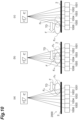
- FIG. 10 is a schematic diagram illustrating the inspection target object F conveyed on a conveyance unit 2000.
- each of line sensors 1001 to 1006 of an X-ray detection camera 1000 is in a state in which exposure with the X-ray can be performed to output the X-ray image
- each of the line sensors 1001 to 1006 is in the dead time.
- a front end Fa of the inspection target object F is imaged by the line sensors 1001 and 1002 in FIG. 10(a) , and is imaged by the line sensor 1006 in FIG. 10(c) .
- a back end Fb of the inspection target object F is imaged by the line sensors 1004 to 1006 in FIG. 10(c) .
- a line sensor as an output source of the X-ray image subjected to the addition processing is different between a portion in which the front end Fa appears and a portion in which the back end Fb appears.
- the parallax between the X-ray image groups subjected to the addition processing occurs.
- the reset operation of performing the voltage control on the detection unit 20 such that the electric charge is not collected by the detection unit 20 is executable based on the signal from the target object sensor 8 that senses the inspection target object F irradiated with the X-ray.
- the reset operation is executable in consideration of a result of sensing the inspection target object F by the target object sensor 8.
- the reset operation can be executed at a timing when the inspection target object F is not present, and the voltage control can be performed on the detection unit 20 such that the electric charge is collected by the detection unit 20 at a timing when the inspection target object F is present.
- the occurrence of the polarization phenomenon in the detection unit 20 can be suppressed, and the X-ray can be more reliably detected in a case where the X-ray incident on the X-ray detection camera 100 is transmitted through the inspection target object F.
- a configuration using the X-ray detection camera 100 is not a configuration in which the imaging is cyclically turned off as in the comparative example illustrated in FIG.
- the imaging is continuously executed at a timing when the X-ray is transmitted through the inspection target object F, so that the occurrence of the parallax between the X-ray image groups subjected to the addition processing is suppressed in one image obtained by adding a plurality of X-ray images output from the X-ray detection camera 100.
- the determination unit 52 may determine that the reset operation is executable in a case where it is determined that the inspection target object F has not been sensed based on the signal from the target object sensor 8 in the determination processing.
- the reset operation is executed at a timing when the inspection target object F is not present, and for example, the voltage control can be performed on the detection unit 20 such that the electric charge is collected by the detection unit 20 at a timing when the inspection target object F is present.
- the occurrence of the polarization phenomenon in the detection unit 20 can be suppressed, and the X-ray can be more reliably detected in a case where the X-ray incident on the X-ray detection camera 100 is transmitted through the inspection target object F.
- the X-ray detection camera 100 includes the target object sensor 8. With such a configuration, the above-described control can be appropriately performed based on a signal from the target object sensor 8 provided as an internal component.
- the target object sensor 8 is provided on the same substrate as the detection unit 20 (see FIG. 2 ). With such a configuration, it is possible to suppress an increase in size of the apparatus.
- the determination unit 52 may not execute the determination processing until the predetermined period, which is the period in which the reset operation is unnecessary, has elapsed after the reset operation is executed, and may execute the determination processing in a case where the predetermined period has elapsed. With such a configuration, it is possible to suppress the execution of the reset operation until it is necessary to eliminate the polarization phenomenon again in the X-ray detection camera 100 after the reset operation is executed. As a result, the X-ray detection camera 100 can be operated more efficiently.
- the detection unit 20 may be operated based on the reference clock, and the determination unit 52 may determine whether the predetermined period has elapsed by counting the reference clock. With such a configuration, it is possible to more accurately determine whether or not the predetermined time has elapsed based on the reference clock. As a result, it is possible to more reliably suppress the execution of the reset operation until it is necessary to eliminate the polarization phenomenon again in the X-ray detection camera 100 after the reset operation is executed.
- the reset operation may be one of the operation of stopping the application of the voltage to the detection unit 20 and the operation of applying the reverse bias voltage to the detection unit 20. With such a configuration, the polarization phenomenon in the X-ray detection camera 100 can be more reliably eliminated.
- the X-ray inspection apparatus 1A includes the above-described X-ray detection camera 100, the X-ray generator 3 that emits the X-ray, and the conveyance unit 2 that conveys the inspection target object F such that the inspection target object F passes through the X-ray irradiation region R3.
- the X-ray emitted from the X-ray generator 3 is transmitted through the inspection target object F, so that, for example, the reset operation can be executed at a timing when the inspection target object F is not present, and the voltage control can be performed on the detection unit 20 such that the electric charge is collected by the detection unit 20 at a timing when the inspection target object F is present.
- the occurrence of the polarization phenomenon in the detection unit 20 can be suppressed, and the X-ray can be more reliably detected in a case where the X-ray incident on the X-ray detection camera 100 is transmitted through the inspection target object F.
- the present invention is not limited thereto, and various modified examples can be applied.
- FIG. 11 is a configuration diagram of an X-ray inspection apparatus 1B according to a modified example.
- the X-ray inspection apparatus 1B is different from the X-ray inspection apparatus 1A in a configuration of a conveyance unit 2B (conveyance apparatus) that conveys an inspection target object F.
- the conveyance unit 2B is dividedly formed so as not to be present on a line connecting a light source 7 and a target object sensor 8 (so as to form a gap).
- the conveyance unit 2B is formed so as not to be present on the line connecting the light source 7 and the target object sensor 8, so that the inspection target object F can be sensed with high accuracy without being affected by the conveyance unit 2B.
- FIG. 12 is a configuration diagram of an X-ray inspection apparatus 1C according to a modified example.
- an inspection target object F is sensed by a sensor 88 (an example of the target object sensor 8) provided outside an X-ray detection camera 100, and the above-described determination processing is executed based on an external signal from the sensor 88.
- a control unit 50 of the X-ray inspection apparatus 1C functions as a signal input unit that receives an input of the external signal from the sensor 88. Then, the control unit 50 executes the above-described determination processing based on the external signal. With such a configuration, it is possible to reliably receive a signal from the target object sensor 8 provided outside the X-ray detection camera 100 and appropriately perform control based on the signal.
- a plurality of light sources 77 that irradiate the inspection target object F with light for target object sensing are provided.
- a plurality of sensors 88 are provided as sensors that detect the light emitted from the light source 77.
- the plurality of sensors 88 are provided in the vicinity of a conveyance path of the inspection target object F.
- the sensor 88 may be, for example, a camera equipped with a photoelectric sensor such as a photodiode.
- the light (signal) detected by the sensor 80 may be a reflected image or a transmitted image.
- the light detected by the sensor 88 may be visible light, infrared light, or an X-ray image.
- the sensor 88 may include a weight sensor, a magnetic sensor, a laser sensor, a radio wave sensor, an ultrasonic sensor, a contact sensor, and the like other than the photoelectric sensor. Note that, as a configuration in which an external signal is acquired from a sensor provided outside, a configuration in which an external signal is acquired from an apparatus such as a weight checker, a central control apparatus (sequencer), or the like may be adopted.
- FIG. 13 is a diagram for describing an example of a reset operation based on an external signal from an external apparatus (here, the sensor 88).
- the horizontal axis represents time
- the vertical axis represents a state of an input trigger.
- the input trigger here is, for example, a trigger linked to completion of the determination processing.
- the reset operation may be executed at a timing when the input trigger rises, and when the reset operation is completed, exposure (capturing of the X-ray image) may be automatically performed to acquire images of an arbitrary number of lines.
- a level and polarity ("P" or "N") of the input trigger are not particularly limited.
- an arbitrary delay time may be provided in the X-ray detection camera 100 for the input trigger, and then the reset operation may be executed.
- Such a delay time may be set in consideration of use of the external signal from the sensor 88, which is the external apparatus, for example.
- the reset operation and the exposure may be performed according to a high/low period of the input trigger.
- the reset operation is executed in a period in which the input trigger is high, and the exposure (capturing of the X-ray image) is performed in a period in which the input trigger is Low.
- a rising edge of the input trigger is detected, and the reset operation may be executed only for a predetermined period after the rising edge is detected.
- the rising edge is a portion where the input trigger rises (increases) sharply in a graph as illustrated in FIG. 13 .
- a change amount of the input trigger within a minute time exceeds a predetermined threshold.
- a reset operation time does not have to be set to a constant value, and may be set based on, for example, a table of cycles of the reset operation time provided in advance.
- control may be performed such that the reset operation time is lengthened (firmly reset) in the period in which the inspection target object F is not continuous.
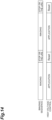
- FIG. 14 is a diagram illustrating a sequence of the X-ray inspection apparatus according to the modified example.
- the determination unit 52 of the control unit 50 executes the determination processing based on sequence data which is repetition of an imaging period and a non-imaging period set in advance.
- FIG. 14 illustrates sequences of imaging and high voltage control.
- the horizontal axis represents time.
- "Imaging" in the imaging sequence of FIG. 14 indicates the imaging period, and "stop or the like" indicates the non-imaging period.
- the control unit 50 can easily and appropriately execute the reset operation by acquiring information of the imaging sequence. Note that, as illustrated in FIG.
- the high voltage control sequence is set corresponding to the imaging sequence, a first bias power supply 30 applies a high voltage to a semiconductor crystal 21 in the imaging period, and the first bias power supply 30 executes the reset operation on the semiconductor crystal 21 in the non-imaging period.
- FIG. 15 is a configuration diagram of an X-ray inspection apparatus 1D that executes determination processing based on sequence data.
- the X-ray inspection apparatus 1D includes an X-ray generator 3, an X-ray detection camera 100, and a conveyance unit 2D.
- an inspection target object F placed on the conveyance unit 2D is irradiated with an X-ray along an irradiation line 500.
- the foldback irradiation line 500 is set for the inspection target object F.
- FIG. 16 is a diagram illustrating a configuration of a stage 150.
- the X-ray inspection apparatus 1D includes the stage 150 that moves the X-ray generator 3 and the X-ray detection camera 100 relative to the inspection target object F.
- the stage 150 includes an arm portion that holds both the X-ray generator 3 and the X-ray detection camera 100.
- a control unit 50 controls the stage 150 to irradiate the inspection target object F with the X-ray along the foldback irradiation line 500.
- FIG. 17 is a diagram illustrating an inspection method for the inspection target object F using the X-ray inspection apparatus 1D.
- FIG. 18 is a diagram illustrating a movement speed for each time in the X direction and the Y direction in the inspection method.
- a broken line portion indicates an imaging period
- a solid line portion indicates a reset period
- a circle indicates a reset start timing.
- FIG. 17(a) illustrates an example in which the foldback irradiation line 500 is set for the inspection target object F having a rectangular shape in plan view.
- the control unit 50 controls the stage 150 such that the X-ray generator 3 and the X-ray detection camera 100 move in the X direction in the imaging period, and the X-ray generator 3 and the X-ray detection camera 100 move in the Y direction in the non-imaging period (reset period).
- FIG. 18 movement when moving in the X direction is maintained at a constant speed in a predetermined period.
- the control unit 50 controls the stage 150 such that the X-ray generator 3 and the X-ray detection camera 100 move in the X direction at a constant speed with respect to the inspection target object F in the imaging period.
- movement when moving in the Y direction is performed so as to first accelerate (accelerate with respect to the inspection target object F) and then decelerate (decelerate with respect to the inspection target object F). That is, the control unit 50 controls the stage 150 such that the X-ray generator 3 and the X-ray detection camera 100 accelerate or decelerate in the non-imaging period. It is sufficient if the stage 150 moves the X-ray generator 3 and the X-ray detection camera 100 relative to the inspection target object F.
- the stage 150 may fix positions of the X-ray generator 3 and the X-ray detection camera 100, and the X-ray generator 3 and the X-ray detection camera 100 may move relative to the inspection target object F as the inspection target object F moves by any method.
- the X-ray generator 3 and the X-ray detection camera 100 first move in the X direction in the imaging period, move in the Y direction when the resetting is started in the non-imaging period, turn back and move in a -X direction in the imaging period, move in the Y direction when the resetting is started in the non-imaging period, turn back and move in the X direction in the imaging period, move in the Y direction when the resetting is started in the non-imaging period, turn back and move in the -X direction in the imaging period, move in the Y direction when the resetting is started in the non-imaging period, and move in the X direction finally in the imaging period.
- FIG. 17(b) illustrates an example in which the foldback irradiation line 500 is set for the inspection target object F having a stepped shape in which an upper right portion of a rectangle is cut out. Since the inspection target object F having such a shape is not present at a step portion, control is performed such that the step portion is in a reset period as illustrated in FIG. 17(b) .
- the reset operation can be executed in the non-imaging period, and the voltage control on a detection element can be performed such that an electric charge is collected by the X-ray detection camera 100 in the imaging period.
- occurrence of the polarization phenomenon in the X-ray detection camera 100 can be suppressed, and the X-ray can be more reliably detected in a case where the X-ray is transmitted through the inspection target object F.
- the X-ray generator 3 and the X-ray detection camera 100 move at a constant speed in the imaging period to appropriately perform the imaging, and the X-ray generator 3 and the X-ray detection camera 100 accelerate or decelerate depending on a situation in the non-imaging period, so that it is possible to efficiently move the X-ray generator 3 and the X-ray detection camera 100.
- FIG. 19 is a configuration diagram of X-ray inspection apparatuses according to modified examples.
- an X-ray detection camera 100 is controlled such that a rotating inspection target object F is irradiated with an X-ray from an X-ray generator 3, and a reset operation and imaging are executed at every predetermined angle.
- a section T1 in which an inspection target object F is not cyclically conveyed is set, and a reset operation is executed in a period corresponding to the section.
- FIG. 20 is a configuration diagram of an X-ray inspection apparatus 1G according to a modified example.
- a control unit 50 of an X-ray detection camera 100 outputs an output signal for stopping an operation related to imaging in the X-ray inspection apparatus 1D to a conveyance unit 2, an X-ray generator 3, and a control apparatus 4.
- the control unit 50 may output an output signal for controlling the conveyance unit 2 to stop conveyance to the outside of the X-ray detection camera 100, specifically, the conveyance unit 2.
- the control unit 50 may stop the conveyance in the conveyance unit 2 by stopping an output signal (stage drive trigger) output when the conveyance is performed in the conveyance unit 2.
- the conveyance unit 2 may be controlled by the control apparatus 4.
- the control unit 50 outputs an output signal for requesting stop of the conveyance in the conveyance unit 2 to the control apparatus 4. Then, the control apparatus 4 receives the output signal and stops the conveyance in the conveyance unit 2.
- the control unit 50 may output an output signal for stopping irradiation with an X-ray by the X-ray generator 3 to the outside of the X-ray detection camera 100, specifically, to the X-ray generator 3.
- the control unit 50 may output an output signal (light source drive trigger) such that the X-ray generator 3 emits the X-ray.
- the control unit 50 may stop the output signal in a case where the reset operation is executed by the first bias power supply 30.
- the control unit 50 may transmit an output signal for requesting stop of the irradiation with the X-ray by the X-ray generator 3 to the control apparatus 4.
- the control apparatus 4 receives the request and controls the X-ray generator 3 so as to stop the irradiation with the X-ray.
- FIG. 21 is a configuration diagram of an X-ray inspection apparatus 1H according to a modified example.
- the X-ray inspection apparatus 1H includes a shutter 600 in addition to the configuration of the X-ray inspection apparatus 1G described above.
- the shutter 600 is provided immediately below an X-ray generator 3, and is configured to adjust an exposure dose of an X-ray by being opened and closed.
- a control unit 50 outputs an output signal for instructing the shutter 600 to be opened and closed.
- the control unit 50 outputs an output signal for stopping irradiation with the X-ray by the X-ray generator 3 to the X-ray generator 3.
- the opening and closing of the shutter 600 and the irradiation with the X-ray from the X-ray generator 3 are adjusted under the control of the control unit 50, and the exposure dose of the X-ray can be reduced.
- the exposure dose of the X-ray By reducing the exposure dose of the X-ray, the progress of polarization can be suppressed.
Landscapes
- Health & Medical Sciences (AREA)
- General Physics & Mathematics (AREA)
- Life Sciences & Earth Sciences (AREA)
- Physics & Mathematics (AREA)
- Immunology (AREA)
- Biochemistry (AREA)
- General Health & Medical Sciences (AREA)
- Analytical Chemistry (AREA)
- Chemical & Material Sciences (AREA)
- Pathology (AREA)
- High Energy & Nuclear Physics (AREA)
- Molecular Biology (AREA)
- Spectroscopy & Molecular Physics (AREA)
- Analysing Materials By The Use Of Radiation (AREA)
- Toxicology (AREA)
- Solid State Image Pick-Up Elements (AREA)
- Transforming Light Signals Into Electric Signals (AREA)
Abstract
Description
- One aspect of the present invention relates to a radiation detection apparatus, a radiation detection system, and a radiation detection method.
- Hitherto, a radiation detection apparatus that detects radiation transmitted through a target object is known. In such a radiation detection apparatus, for example, the radiation transmitted through the target object is directly converted into an electric charge by a direct conversion material of a detection element, and the electric charge is collected by a pixel electrode, whereby the radiation is detected and a radiation captured image is obtained. Here, in such a radiation detection apparatus, when the detection element is continuously irradiated with the radiation, a polarization phenomenon (polarization) occurs in the detection element, and the radiation captured image may deteriorate. Therefore, it is required to eliminate the polarization phenomenon in the detection element.
- In a radiation detection apparatus described in
Patent Literature 1, the polarization phenomenon in the radiation detection apparatus is eliminated by turning on/off a high voltage (HV) supplied from a HV power supply apparatus to the radiation detection apparatus at a predetermined cycle. - In a pair of radiation detection apparatuses described in
Patent Literature 2, when a bias voltage is supplied from a bias power supply to the radiation detection apparatus configuring one array, a supply destination of the bias voltage is switched to the radiation detection apparatus configuring the other array before the polarization phenomenon occurs in the radiation detection apparatus configuring one array, thereby suppressing the occurrence of the polarization phenomenon in the radiation detection apparatus. - In a plurality of radiation detection apparatuses described in
Patent Literature 3, a bias voltage is applied such that stop periods of bias application to the respective radiation detection apparatuses do not overlap each other, thereby suppressing simultaneous occurrence of the polarization phenomenon in the plurality of radiation detection apparatuses. -
- Patent Literature 1:
Japanese Unexamined Patent Publication No. 2006-513406 - Patent Literature 2:
Japanese Unexamined Patent Publication No. 2008-304420 - Patent Literature 3: International Patent Publication No.
WO 2009/122665 A - In the above-described radiation detection apparatus, the application of the bias voltage is stopped without considering a situation outside the radiation detection apparatus in order to eliminate the polarization phenomenon in the radiation detection apparatus. Therefore, in a case where a timing at which the polarization phenomenon in the detection element is eliminated in the radiation detection apparatus overlaps a timing at which the radiation incident on the radiation detection apparatus is transmitted through the target object, there is a possibility that the radiation detection apparatus cannot detect the radiation transmitted through the target object.
- One aspect of the present invention has been made in view of the above circumstances, and relates to a radiation detection apparatus, a radiation detection system, and a radiation detection method capable of suppressing occurrence of a polarization phenomenon in a detection element and more reliably detecting radiation incident on the radiation detection apparatus when the radiation is transmitted through a target object.
-
- (1) A radiation detection apparatus according to an aspect of the present invention includes: a detection element configured to directly convert incident radiation into an electric charge and output a result of collecting the electric charge for each of a plurality of pixel electrodes as captured image data; a voltage source configured to apply a bias voltage to the detection element; and a control unit electrically connected to the detection element and the voltage source, in which the control unit includes a determination unit configured to execute determination processing of determining whether or not a reset operation of performing voltage control on the detection element such that the electric charge is not collected by the detection element is executable, and a voltage control unit configured to control the voltage source to execute the reset operation in a case where the determination unit determines that the reset operation is executable, and the determination unit executes the determination processing based on a signal from a target object sensor that senses a target object irradiated with the radiation.
In the radiation detection apparatus according to an aspect of the present invention, it is determined whether or not the reset operation of performing the voltage control on the detection element such that the electric charge is not collected by the detection element is executable based on the signal from the target object sensor that senses the target object irradiated with the radiation. With such a configuration, it is determined whether or not the reset operation is executable in consideration of a result of sensing the target object by the target object sensor. As a result, for example, the reset operation can be executed at a timing when the target object is not present, and the voltage control can be performed on the detection element such that the electric charge is collected by the detection element at a timing when the target object is present. As a result, occurrence of a polarization phenomenon in the detection element can be suppressed, and the radiation incident on the radiation detection apparatus can be more reliably detected in a case where the radiation is transmitted through the target object. - (2) In the radiation detection apparatus according to (1), the determination unit may determine that the reset operation is executable in a case where it is determined that the target object has not been sensed based on the signal from the target object sensor in the determination processing. With such a configuration, the reset operation is executed at a timing when the target object is not present, and for example, the voltage control can be performed on the detection element such that the electric charge is collected by the detection element at a timing when the target object is present. As a result, the occurrence of the polarization phenomenon in the detection element can be suppressed, and the radiation incident on the radiation detection apparatus can be more reliably detected in a case where the radiation is transmitted through the target object.
- (3) The radiation detection apparatus according to (1) or (2) may further include a signal input unit configured to receive an input of the signal from the target object sensor. With such a configuration, it is possible to reliably receive the signal from the target object sensor provided outside the radiation detection apparatus and appropriately perform control based on the signal.
- (4) The radiation detection apparatus according to (1) or (2) may further include the target object sensor. With such a configuration, the above-described control can be appropriately performed based on a signal from the target object sensor provided as an internal component.
- (5) In the radiation detection apparatus according to (4), the target object sensor may be provided on the same substrate as the detection element. With such a configuration, it is possible to suppress an increase in size of the apparatus.
- (6) In the radiation detection apparatus according to (1) to (5), the determination unit may not execute the determination processing until a predetermined period, which is a period in which the reset operation is unnecessary, elapses after the reset operation is executed, and may execute the determination processing in a case where the predetermined period has elapsed. With such a configuration, it is possible to suppress the execution of the reset operation until it is necessary to eliminate the polarization phenomenon again in the radiation detection apparatus after the reset operation is executed. As a result, the radiation detection apparatus can be operated more efficiently.
- (7) In the radiation detection apparatus according to (1) to (6), the detection element may be operated based on a reference clock, and the determination unit may count the reference clock to determine whether or not the predetermined period has elapsed. With such a configuration, it is possible to more accurately determine whether or not the predetermined time has elapsed based on the reference clock. As a result, it is possible to more reliably suppress the execution of the reset operation until it is necessary to eliminate the polarization phenomenon again in the radiation detection apparatus after the reset operation is executed.
- (8) In the radiation detection apparatus according to (1) to (7), the reset operation may be one of an operation of stopping application of a voltage to the detection element and an operation of applying a reverse bias voltage to the detection element. With such a configuration, the polarization phenomenon in the radiation detection apparatus can be more reliably eliminated.
- (9) A radiation detection system according to an aspect of the present invention includes: the radiation detection apparatus according to (1) to (8); a light source configured to emit the radiation; and a conveyance apparatus configured to convey the target object such that the target object passes through an irradiation region of the radiation. In such a radiation detection system, for example, in a situation where the conveyance apparatus sequentially conveys a plurality of target objects, the radiation emitted from the light source is transmitted through the target object, so that, for example, the reset operation can be executed at a timing when the target object is not present, and the voltage control can be performed on the detection element such that the electric charge is collected by the detection element at a timing when the target object is present. As a result, the occurrence of the polarization phenomenon in the detection element can be suppressed, and the radiation incident on the radiation detection apparatus can be more reliably detected in a case where the radiation is transmitted through the target object.
- (10) The radiation detection system according to (9) may further include the target object sensor. With such a configuration, the above-described control can be appropriately performed based on a signal from the target object sensor provided as an internal component.
- (11) A radiation detection method according to an aspect of the present invention includes: a voltage application step of applying a bias voltage to a detection element configured to directly convert incident radiation into an electric charge and output a result of collecting the electric charge for each of a plurality of pixel electrodes as captured image data; an acquisition step of acquiring a signal from a target object sensor configured to sense a target object irradiated with the radiation; a determination step of determining whether or not a reset operation of performing voltage control on the detection element such that the electric charge is not collected by the detection element is executable based on the signal from the target object sensor; and a reset step of executing the reset operation in a case where it is determined in the determination step that the reset operation is executable. With such a configuration, for example, the reset operation can be executed at a timing when the target object is not present, and the voltage control can be performed on the detection element such that the electric charge is collected by the detection element at a timing when the target object is present. As a result, the occurrence of the polarization phenomenon in the detection element can be suppressed, and the radiation incident on the radiation detection apparatus can be more reliably detected in a case where the radiation is transmitted through the target object.
- (12) A radiation detection apparatus according to an aspect of the present invention includes: a detection element configured to directly convert incident radiation into an electric charge and output a result of collecting the electric charge for each of a plurality of pixel electrodes as captured image data; a voltage source configured to apply a bias voltage to the detection element; and a control unit electrically connected to the detection element and the voltage source, in which the control unit includes a determination unit configured to execute determination processing of determining whether or not a reset operation of performing voltage control on the detection element such that the electric charge is not collected by the detection element is executable, and a voltage control unit configured to control the voltage source to execute the reset operation in a case where the determination unit determines that the reset operation is executable, and the determination unit executes the determination processing based on sequence data which is repetition of an imaging period and a non-imaging period set in advance. With such a configuration, it is determined whether or not the reset operation is executable in consideration of the sequence data which is repetition of the imaging period and the non-imaging period set in advance. As a result, for example, the reset operation can be executed in the non-imaging period, and the voltage control on a detection element can be performed such that the electric charge is collected by the detection element in the imaging period. As a result, the occurrence of the polarization phenomenon in the detection element can be suppressed, and the radiation incident on the radiation detection apparatus can be more reliably detected in a case where the radiation is transmitted through the target object.
- (13) A radiation detection system according to an aspect of the present invention includes: the radiation detection apparatus according to (12); a light source configured to emit the radiation; and a stage configured to move the light source and the detection element relative to a target object, in which the control unit controls the stage such that the light source and the detection element move with respect to the target object at a constant speed in the imaging period, and the light source and the detection element accelerate or decelerate with respect to the target object in the non-imaging period. With such a configuration, the light source and the detection element move at a constant speed in the imaging period to appropriately perform the imaging, and the light source and the detection element accelerate or decelerate depending on a situation in the non-imaging period, so that it is possible to efficiently move the light source and the like.
- With the radiation detection apparatus, the radiation detection system, and the radiation detection method according to one aspect of the present invention, the occurrence of the polarization phenomenon in the detection element can be suppressed and radiation incident on the radiation detection apparatus can be more reliably detected when the radiation is transmitted through a target object.
-
-
FIG. 1 is a configuration diagram of an X-ray inspection apparatus according to an embodiment. -
FIG. 2 is a configuration diagram of an X-ray detection camera. -
FIG. 3 is a view illustrating a configuration example of a radiation detection unit and a sensing unit. -
FIG. 4 is a view illustrating a configuration example of an imaging sensor and a sensor. -
FIG. 5 is a block diagram illustrating a functional configuration of a control unit. -
FIG. 6 is a diagram for describing control according to a distance between inspection target objects F. -
FIG. 7 is a diagram for describing an example of a reset operation. -
FIG. 8 is a flowchart illustrating processing executed by the X-ray inspection apparatus. -
FIG. 9 is a diagram for describing problems in an X-ray detection camera according to a comparative example. -
FIG. 10 is a diagram for describing problems in the X-ray detection camera according to the comparative example. -
FIG. 11 is a configuration diagram of an X-ray inspection apparatus according to a modified example. -
FIG. 12 is a configuration diagram of an X-ray inspection apparatus according to a modified example. -
FIG. 13 is a diagram for describing an example of a reset operation based on a signal from an external apparatus. -
FIG. 14 is a diagram illustrating a sequence of an X-ray inspection apparatus according to a modified example. -
FIG. 15 is a configuration diagram of an X-ray inspection apparatus according to a modified example. -
FIG. 16 is a diagram for describing a configuration of a stage. -
FIG. 17 is a diagram for describing an inspection method for the inspection target object. -
FIG. 18 is a diagram illustrating a processing speed for each time in an X direction and a Y direction. -
FIG. 19 is a configuration diagram of X-ray inspection apparatuses according to modified examples. -
FIG. 20 is a configuration diagram of an X-ray inspection apparatus according to a modified example. -
FIG. 21 is a configuration diagram of an X-ray inspection apparatus according to a modified example. - Hereinafter, an embodiment of the present invention will be described in detail with reference to the drawings. In the drawings, the same or corresponding parts are denoted by the same reference signs, and redundant description will be omitted.
-
FIG. 1 is a configuration diagram of anX-ray inspection apparatus 1A which is a radiation detection system according to the present embodiment. As illustrated inFIG. 1 , theX-ray inspection apparatus 1A is an apparatus that irradiates an inspection target object (target object) F conveyed in a conveyance direction TD with an X-ray (radiation) and acquires an X-ray image (captured image) obtained by imaging the inspection target object F based on the X-ray transmitted through the inspection target object F. TheX-ray inspection apparatus 1A performs foreign matter inspection, weight inspection, product inspection, and the like targeting on the inspection target object F by using the X-ray image. Examples of the application of theX-ray inspection apparatus 1A include food inspection, baggage inspection, substrate inspection, battery inspection, and material inspection. TheX-ray inspection apparatus 1A includes a conveyance unit (conveyance apparatus) 2 that conveys the inspection target object F, an X-ray generator (light source) 3 that emits the X-ray, anX-ray detection camera 100, alight source 7, atarget object sensor 8, acontrol apparatus 4, and a shieldingportion 5 that blocks the X-ray. Note that the radiation in the present invention is not limited to the X-ray, and includes radiation other than the X-ray, such as a γ-ray. In the present embodiment, description will be made assuming that the radiation is the X-ray. - The
conveyance unit 2 conveys the inspection target object F such that the inspection target object F passes through an irradiation region R3 irradiated with the X-ray by theX-ray generator 3. Theconveyance unit 2 includes abelt 2a on which the inspection target object F is placed. In theconveyance unit 2, thebelt 2a moves in the conveyance direction TD, so that the inspection target object F is conveyed in the conveyance direction TD at a predetermined conveyance speed. A plurality of inspection target objects F are placed on thebelt 2a at predetermined intervals. Each inspection target object F is sequentially conveyed to the irradiation region R3 as thebelt 2a moves. Note that examples of the inspection target object F conveyed by theconveyance unit 2 include various articles including food such as meat, fish and shellfish, agricultural products, and confectionery, rubber products such as tires, resin products, metal products, resource materials such as minerals, wastes, electronic components, and electronic substrates. - The
X-ray generator 3 is an apparatus that irradiates the inspection target object F with the X-ray (outputs the X-ray) as an X-ray source. TheX-ray generator 3 is, for example, a point light source, and diffuses and emits the X-ray in a constant irradiation direction (a predetermined angular range). TheX-ray generator 3 is provided such that the irradiation direction is on aconveyance unit 2 side. TheX-ray generator 3 is provided above theconveyance unit 2 so as to be separated from theconveyance unit 2 by a predetermined distance. TheX-ray generator 3 is provided such that the X-ray irradiation region R3 extends over the entire width direction (a direction intersecting the conveyance direction TD) of the inspection target object F. TheX-ray generator 3 sets a predetermined division range in a length direction as the irradiation region R3 in the length direction (the conveyance direction TD) of the inspection target object F. In theX-ray inspection apparatus 1A, the inspection target object F is conveyed by theconveyance unit 2, and the entire inspection target object F passes through the irradiation region R3 of theX-ray generator 3, so that the inspection target object F is irradiated with the X-ray over the entire length direction. In theX-ray generator 3, for example, a tube voltage and a tube current are set by thecontrol apparatus 4. TheX-ray generator 3 irradiates theconveyance unit 2 with the X-ray having predetermined energy and radiation dose according to the set tube voltage and tube current. - The
X-ray detection camera 100 detects the X-ray transmitted through at least theconveyance unit 2 among the X-rays emitted toward theconveyance unit 2 by theX-ray generator 3, and outputs the X-ray image based on the X-ray. The X-ray detection camera (radiation detection apparatus) 100 is, for example, an X-ray flat panel sensor or an X-ray line sensor camera, and includes a radiation detection unit (detection element) 20x (seeFIG. 2 ) including at least one row of pixel lines in which a plurality of pixels are arranged in a pixel arrangement direction. Theradiation detection unit 20x is a direct conversion type radiation detection element that directly converts an incident X-ray into an electric charge. TheX-ray detection camera 100 generates the X-ray image based on the detected X-ray, and outputs the generated X-ray image to thecontrol apparatus 4. Note that theradiation detection unit 20x of theX-ray detection camera 100 may be a one-dimensional sensor (single-line sensor) in which one pixel line is provided, or may be a two-dimensional sensor including a plurality of pixel lines. The two-dimensional sensor may be an area scanning type two-dimensional sensor. Furthermore, a line scanning type two-dimensional sensor such as a multi-line sensor including a plurality of pixel lines or a time delay integration (TDI) sensor may be used. - The
light source 7 irradiates the inspection target object F with light for target object sensing (outputs the light for target object sensing). It is sufficient if thelight source 7 outputs light that can be sensed by thetarget object sensor 8, and may output visible light, infrared light, or the X-ray, for example. Thelight source 7 is provided above theconveyance unit 2, for example. Note that, in the present embodiment, thetarget object sensor 8 senses the light output from thelight source 7 and transmitted through the inspection target object F, and thus, thelight source 7 is provided on an opposite side of the inspection target object F from the target object sensor 8 (that is, above the conveyance unit 2). However, in a case where thetarget object sensor 8 senses the light output from thelight source 7 and reflected by the inspection target object F, thelight source 7 may be provided below theconveyance unit 2 similarly to thetarget object sensor 8. Thelight source 7 and thetarget object sensor 8 are not limited to be installed in a vertical direction, and may be installed in a horizontal direction. When thelight source 7 and thetarget object sensor 8 are installed in the horizontal direction, thelight source 7 and thetarget object sensor 8 may be installed in the width direction (a direction intersecting the conveyance direction TD) of the inspection target object F, in the length direction (the conveyance direction TD) of the inspection target object F, or in an oblique direction including the width direction and the length direction. Furthermore, a member that reflects light, such as a mirror, may be provided between thelight source 7 and thetarget object sensor 8. Thelight source 7 and thetarget object sensor 8 may be integrated with each other. - The
target object sensor 8 is a sensor that senses the inspection target object F. Thetarget object sensor 8 senses the inspection target object F by sensing the light output from thelight source 7. In the present embodiment, it is described that thetarget object sensor 8 senses the light transmitted through the inspection target object F, but thetarget object sensor 8 may sense light reflected by the inspection target object F. A specific configuration example of thetarget object sensor 8 is described below. - The
control apparatus 4 is, for example, a computer such as a personal computer (PC). Thecontrol apparatus 4 is electrically connected to theX-ray detection camera 100. Thecontrol apparatus 4 controls theX-ray detection camera 100 to repeatedly perform imaging at a predetermined detection cycle. In a case where theradiation detection unit 20x of theX-ray detection camera 100 includes a plurality of pixel lines, thecontrol apparatus 4 sets the predetermined detection cycle such that each of the plurality of pixel lines can image the X-ray transmitted through the same region of the inspection target object F. Thecontrol apparatus 4 generates an X-ray image based on the X-ray image output from theX-ray detection camera 100. For example, thecontrol apparatus 4 generates one X-ray image by connecting image data of one line output from theX-ray detection camera 100. Thecontrol apparatus 4 may generate one X-ray image by executing averaging processing or addition processing on the data output from theX-ray detection camera 100. Note that thecontrol apparatus 4 may be an apparatus independently provided outside theX-ray detection camera 100 or may be integrated inside theX-ray detection camera 100. - The predetermined detection cycle may be set based on, for example, at least one of a distance between the plurality of pixel lines of the
radiation detection unit 20x, a distance between theX-ray generator 3 and the inspection target object F on the conveyance unit 2 (focus object distance (FOD)), or a distance between theX-ray generator 3 and theradiation detection unit 20x (focus detector distance (FDD)). In addition, the predetermined detection cycle may be individually set based on a pixel width in a direction orthogonal to the pixel arrangement direction of the pixels constituting the pixel line of theradiation detection unit 20x. In this case, a deviation (delay time) of the detection cycle between the plurality of pixel lines may be specified according to the distance between the plurality of pixel lines, the conveyance speed of theconveyance unit 2, the distance (FOD) between theX-ray generator 3 and the inspection target object F on theconveyance unit 2, and the distance (FDD) between theX-ray generator 3 and theradiation detection unit 20x, and the individual cycles may be respectively set. - The shielding
portion 5 prevents the X-ray emitted from theX-ray generator 3 from leaking to the outside of theX-ray inspection apparatus 1A. The shieldingportion 5 is provided so as to surround the periphery of the irradiation region R3 of theX-ray generator 3. The shieldingportion 5 has a carry-inport 5a and a carry-outport 5b through which theconveyance unit 2 and the inspection target object F conveyed by theconveyance unit 2 pass. The carry-inport 5a is formed upstream of the irradiation region R3 of theX-ray generator 3 in theconveyance unit 2. The carry-outport 5b is formed downstream of the irradiation region R3 of theX-ray generator 3 in theconveyance unit 2. In theX-ray inspection apparatus 1A, the inspection target object F conveyed by theconveyance unit 2 passes through the carry-inport 5a, the irradiation region R3 of theX-ray generator 3, and the carry-outport 5b in this order. A shieldingcurtain 5c is provided between the irradiation region R3 and regions of the carry-inport 5a and the carry-outport 5b so as to partition the irradiation region R3 and the regions of the carry-inport 5a and the carry-outport 5b, and suppresses the X-ray from leaking to the outside of theX-ray inspection apparatus 1A. - [Configuration of X-ray Detection Camera]
FIG. 2 is a configuration diagram of theX-ray detection camera 100. As illustrated inFIG. 2 , theX-ray detection camera 100 includes adetection unit 20, a first bias power supply 30 (voltage source), a secondbias power supply 40, acontrol unit 50, and an input/output interface 60. - The
detection unit 20 includes theradiation detection unit 20x which is a detection element that directly converts the incident X-ray into the electric charge and outputs a result of collecting the electric charge for each of a plurality of pixel electrodes as X-ray image data (captured image data). Thedetection unit 20 continuously outputs the X-ray image data. Thedetection unit 20 is operated by thecontrol unit 50 based on a reference clock (described below). Thedetection unit 20 includes asemiconductor crystal 21, asignal processing circuit 22, afirst electrode 23, a plurality ofsecond electrodes 24, and a plurality ofthird electrodes 25. Hereinafter, in thedetection unit 20, a direction in which thesemiconductor crystal 21 and thesignal processing circuit 22 extend is referred to as an X direction, and a direction in which thesemiconductor crystal 21 and thesignal processing circuit 22 are arranged is referred to as a Y direction. - The
first electrode 23 is a bias electrode provided on a surface of thesemiconductor crystal 21 on a side opposite to a side facing thesignal processing circuit 22. Thefirst electrode 23 extends in the X direction which is the pixel arrangement direction, and is integrally configured without being divided. The plurality ofsecond electrodes 24 are pixel electrodes provided on a surface of thesemiconductor crystal 21 on the side facing thesignal processing circuit 22 except for some second electrodes 24 (described below). The plurality ofsecond electrodes 24 are arranged in the X direction. The plurality ofthird electrodes 25 are pixel electrodes provided on a surface of thesignal processing circuit 22 on a side facing thesemiconductor crystal 21. The plurality ofthird electrodes 25 are arranged in the X direction. Each of thethird electrodes 25 corresponds to each of the second electrodes 24 (each of thethird electrodes 25 and each of thesecond electrodes 24 are arranged to face each other in the Y direction), and is electrically connected to the correspondingsecond electrode 24. - The
semiconductor crystal 21 is a semiconductor crystal that directly converts the incident X-ray into the electric charge. Thesemiconductor crystal 21 is implemented by, for example, a semiconductor crystal such as cadmium telluride (Cadotel) (CdTe), zinc cadmium telluride (CdZnTe), or thallium bromide (TIBr). When a bias voltage is applied from the firstbias power supply 30 to thesemiconductor crystal 21, the electric charge generated in thesemiconductor crystal 21 linearly advances to thesecond electrode 24 in the Y direction. As a result, the electric charge generated immediately above each of thesecond electrodes 24 reaches thesecond electrode 24 positioned immediately below. The electric charge that has reached thesecond electrode 24 is collected by thethird electrode 25 corresponding to thesecond electrode 24. - The
signal processing circuit 22 is, for example, an application specific integrated circuit (ASIC). Thesignal processing circuit 22 is electrically connected to thesecond electrode 24 via thethird electrode 25. Thesignal processing circuit 22 is a circuit that reads an electric signal between thefirst electrode 23 and thesecond electrode 24, and generates the X-ray image data (captured image data) based on the read electric signal. Thesignal processing circuit 22 collects the electric charge for each of the plurality ofthird electrodes 25, and outputs the collected result to thecontrol unit 50 as the X-ray image data. Thesignal processing circuit 22 continuously outputs the X-ray image data to thecontrol unit 50. Note that the X-ray image data includes a digital signal obtained by converting a voltage signal detected by thesignal processing circuit 22. The X-ray image data may be the X-ray image itself or information for generating the X-ray image. - The first
bias power supply 30 applies the bias voltage to theradiation detection unit 20x of thedetection unit 20. The firstbias power supply 30 is electrically connected to thefirst electrode 23. The firstbias power supply 30 applies the bias voltage to thesemiconductor crystal 21 via thefirst electrode 23 according to a control signal from thecontrol unit 50. The firstbias power supply 30 applies, for example, a high voltage (HV) to thesemiconductor crystal 21. The firstbias power supply 30 is configured to execute a reset operation (described below) on thesemiconductor crystal 21. The secondbias power supply 40 is electrically connected to thesignal processing circuit 22 and provides power for operating thesignal processing circuit 22. The secondbias power supply 40 may be a reference potential when the firstbias power supply 30 applies the bias voltage. The secondbias power supply 40 is electrically connected to a photodiode 90 (described below) of asensing unit 20y, and may provide power for operating thephotodiode 90. Note that the bias voltage (ON voltage value) to be applied to theradiation detection unit 20x of thedetection unit 20 by the firstbias power supply 30 may be arbitrarily set, and is, for example, -1000 V. - The
control unit 50 is electrically connected to thesignal processing circuit 22 and the firstbias power supply 30. Thecontrol unit 50 is implemented by, for example, a field-programmable gate array (FPGA). Thecontrol unit 50 controls thedetection unit 20 by controlling thesignal processing circuit 22 and the firstbias power supply 30 based on the reference clock input from the outside of theX-ray detection camera 100. Furthermore, thecontrol unit 50 may control thedetection unit 20 by controlling thesignal processing circuit 22 and the firstbias power supply 30 based on the reference clock generated in theX-ray detection camera 100. According to any of these, thecontrol unit 50 outputs a control signal for operating thesignal processing circuit 22 to thesignal processing circuit 22. Thecontrol unit 50 acquires the X-ray image data output from thesignal processing circuit 22, and outputs the X-ray image data to the outside of theX-ray detection camera 100. For example, thecontrol unit 50 outputs the X-ray image to thecontrol apparatus 4 via the input/output interface 60. Thecontrol unit 50 outputs the control signal for operating the firstbias power supply 30 to the firstbias power supply 30. Furthermore, thecontrol unit 50 may acquire a control signal from thecontrol apparatus 4 via the input/output interface 60. Note that in a case where the X-ray image data is the information for generating the X-ray image, thecontrol unit 50 may generate the X-ray image based on the acquired X-ray image data. - Here, as illustrated in
FIG. 2 , some of the plurality ofsecond electrodes 24 described above is connected not to thesemiconductor crystal 21 but to another photodetector (here, thephotodiode 90 as an example). Thephotodiode 90 detects the light emitted from thelight source 7. Thesecond electrode 24 connected to thephotodiode 90 is electrically connected to thesignal processing circuit 22 via thethird electrode 25. Thesignal processing circuit 22 outputs a signal corresponding to a detection result of thephotodiode 90 to thecontrol unit 50 based on the read electric signal. Such components (thephotodiode 90, thesecond electrode 24 connected to thephotodiode 90, thethird electrode 25 electrically connected to thesecond electrode 24, and the signal processing circuit 22) related to the output of the detection result of thephotodiode 90 function as thesensing unit 20y related to sensing of the inspection target object F. A case where the inspection target object F is sensed by thesensing unit 20y is a case where the inspection target object F is present in the irradiation region R3 of theX-ray generator 3. Thesensing unit 20y is an example of thetarget object sensor 8 described above. In this case, thetarget object sensor 8 is provided on the same substrate as thedetection unit 20. In thedetection unit 20, a component related to the generation of the X-ray image data is theradiation detection unit 20x, and a component related to the sensing of the inspection target object F is thesensing unit 20y. Theradiation detection unit 20x and thesensing unit 20y may or do not have to have sensitivity in the same wavelength/energy band. The light (signal) detected by theradiation detection unit 20x may be a reflected image or a transmitted image. -
FIG. 3 is a diagram illustrating a configuration example of theradiation detection unit 20x and thesensing unit 20y (the target object sensor 8), and is plan views of theradiation detection unit 20x and thesensing unit 20y. InFIGS. 3(a) to 3(e) , the vertical direction is the conveyance direction of the inspection target object F. As illustrated inFIG. 3(a) , thesensing units 20y may be provided line by line so as to sandwich theradiation detection unit 20x in the conveyance direction. In this case, for example, thesensing units 20y that sense the inspection target object F can be provided for both forward conveyance and reverse conveyance of the inspection target object F. - As illustrated in
FIG. 3(b) , onesensing unit 20y may be provided on only one side of theradiation detection unit 20x in the conveyance direction. Furthermore, as illustrated inFIG. 3(c) , thesensing unit 20y may be provided for one pixel instead of one line. Thesensing unit 20y may be provided in a plurality of stages and be capable of TDI addition as a countermeasure for a low-dose condition. In addition, a position of thesensing unit 20y may be an end portion as illustrated inFIG. 3(c) , may be a central portion as illustrated inFIG. 3(d) , or may be any region. In addition, thesensing unit 20y may be adjacent to theradiation detection unit 20x or may be separated from theradiation detection unit 20x. Further, a part of theradiation detection unit 20x may also serve as thesensing unit 20y as illustrated inFIG. 3(e) . - Note that the configuration of the
target object sensor 8 is not limited to the example of thesensing unit 20y described above. Thetarget object sensor 8 may be implemented not by the pixel (thesensing unit 20y) in thedetection unit 20 as described above but by asensor 80 which is a sensor different from thedetection unit 20. Thesensor 80 is a sensor that detects the light emitted from thelight source 7, and may be, for example, a camera equipped with a photoelectric sensor such as a photodiode. Thesensor 80 may or does not have to have sensitivity in the same wavelength/energy band as the detection unit 20 (imaging sensor) related to the generation of the X-ray image data. The light (signal) detected by thesensor 80 may be a reflected image or a transmitted image. -
FIG. 4 is a diagram illustrating a configuration example of thedetection unit 20 and thesensor 80, which are imaging sensors, and is plan views of thedetection unit 20 and thesensor 80. Note that, inFIG. 4 , thedetection unit 20 is illustrated as an "imaging sensor". InFIGS. 4(a) to 4(d) , the vertical direction is the conveyance direction of the inspection target object F. As illustrated inFIG. 4(a) , thesensors 80 may be provided line by line so as to sandwich thedetection unit 20 in the conveyance direction. In this case, for example, thesensor 80 that senses the inspection target object F can be provided for both the forward conveyance and the reverse conveyance of the inspection target object F. - As illustrated in
FIG. 4(b) , onesensor 80 may be provided on only one side of thedetection unit 20 in the conveyance direction. As illustrated inFIG. 4(c) , thesensor 80 may be provided for one pixel instead of one line. Thesensor 80 may be provided in a plurality of stages and be capable of TDI addition as a countermeasure for a low-dose condition. In addition, a position of thesensor 80 may be an end portion as illustrated inFIG. 4(c) , may be a central portion as illustrated inFIG. 4(d) , or may be any region. Hereinafter, thetarget object sensor 8 will be described as being implemented by thesensing unit 20y as illustrated inFIG. 2 . -
FIG. 5 is a block diagram illustrating a functional configuration of thecontrol unit 50. As illustrated inFIG. 5 , thecontrol unit 50 includes anacquisition unit 51, adetermination unit 52, and avoltage control unit 53. Hereinafter, each functional unit of thecontrol unit 50 will be specifically described. Thecontrol unit 50 determines the presence or absence of the inspection target object F and controls application of the high voltage (HV) by the firstbias power supply 30 according to the determination result. - The
acquisition unit 51 acquires the control signal for controlling imaging in theX-ray detection camera 100 from thecontrol apparatus 4. Theacquisition unit 51 may acquire the control signal generated by thecontrol unit 50 based on the reference clock generated in theX-ray detection camera 100. Theacquisition unit 51 outputs the acquired control signal to thesignal processing circuit 22 or the firstbias power supply 30. Theacquisition unit 51 acquires the X-ray image data from thesignal processing circuit 22. Theacquisition unit 51 outputs the X-ray image to thecontrol apparatus 4. Theacquisition unit 51 acquires a signal from thesensing unit 20y implementing thetarget object sensor 8 via thesignal processing circuit 22. The signal is a signal corresponding to the detection result of thephotodiode 90, and is a signal related to the sensing of the inspection target object F. Theacquisition unit 51 outputs the signal from thesensing unit 20y to thedetermination unit 52. - The
determination unit 52 executes predetermined determination processing based on the signal acquired by theacquisition unit 51 from thesensing unit 20y (the signal from thetarget object sensor 8 that senses the inspection target object F irradiated with the X-ray). The determination processing here is processing of determining whether or not the reset operation is executable. - The reset operation is an operation for eliminating a change in an internal electric field, which is a polarization phenomenon (polarization) occurring inside the
semiconductor crystal 21 when thesemiconductor crystal 21 is continuously irradiated with the X-ray. Specifically, the reset operation is an operation of performing voltage control on thedetection unit 20 such that the electric charge is not collected in thesemiconductor crystal 21. For example, the reset operation may be an operation of stopping application of a voltage to thesemiconductor crystal 21 itself, or may be an operation of applying a reverse bias voltage (a voltage of a reverse bias to a normally applied voltage) to thesemiconductor crystal 21. Note that the voltage (OFF voltage value) applied to thedetection unit 20 when the firstbias power supply 30 executes the reset operation may be arbitrarily set, and may be, for example, 0 V or 10 V. In addition, a period during which the reset operation is executed may be a period necessary for recovery from the polarization phenomenon in thesemiconductor crystal 21. The period during which the reset operation is executed may be, for example, a fixed value, and may be, for example, 1 millisecond. Furthermore, the period during which the reset operation is executed may be changed periodically (cyclically). For example, 1 millisecond and 2 milliseconds may be alternately set as the period during which the reset operation is executed. Note that, when the reset operation is executed, thesignal processing circuit 22 cannot collect the electric charge and thus cannot generate the X-ray image data. - Specifically, the
determination unit 52 determines whether or not the inspection target object F is present in the irradiation region R3 of theX-ray generator 3 based on the signal from thesensing unit 20y. For example, thedetermination unit 52 determines whether the light is the light transmitted through the inspection target object F or the light related to a background luminance and not transmitted through the inspection target object F based on a luminance of the light output from thelight source 7, indicated in the signal from thesensing unit 20y. In a case where the light output from thelight source 7 is transmitted through the inspection target object F, thedetermination unit 52 determines that the inspection target object F is present in the irradiation region R3 of theX-ray generator 3. For example, in a case where a luminance value indicated in the signal from thesensing unit 20y does not exceed a predetermined threshold, thedetermination unit 52 may determine that the light output from thelight source 7 is transmitted through the inspection target object F (the inspection target object F is present in the irradiation region R3 of the X-ray generator 3). - For example, in a case where a configuration in which a light shielding object or a mark is provided between the plurality of inspection target objects F in the
conveyance unit 2 is used, a luminance of light transmitted through the light shielding object or the like becomes low, and thus thedetermination unit 52 may determine that the light output from thelight source 7 is transmitted through the inspection target object F (the inspection target object F is present in the irradiation region R3 of the X-ray generator 3) in a case where the luminance value indicated in the signal from thesensing unit 20y does not exceed the predetermined threshold. - In a case where it is determined that the inspection target object F has not been sensed (the inspection target object F is not present in the irradiation region R3 of the X-ray generator 3) based on the signal from the
sensing unit 20y in the determination processing, thedetermination unit 52 determines that the reset operation is executable. That is, thedetermination unit 52 determines that the reset operation is executable in a case where the inspection target object F is not present and imaging of the inspection target object F is not affected. Thedetermination unit 52 outputs a result of the execution of the determination processing to thevoltage control unit 53. - In a case where the reset operation is executed by the
voltage control unit 53, thedetermination unit 52 does not have to execute new determination processing until a predetermined period elapses thereafter. In this case, thedetermination unit 52 executes new determination processing in a case where the predetermined period has elapsed. The predetermined period is a period in which the reset operation is unnecessary. The period in which the reset operation is unnecessary is a period in which the above-described polarization phenomenon does not become a problem after the reset operation. As described above, the X-ray image data cannot be generated during the reset operation. Therefore, it is preferable that the reset operation is executed to the minimum necessary. The X-ray image data can be more appropriately generated by appropriately setting and managing the period in which the reset operation is unnecessary. Thedetermination unit 52 may determine whether or not the predetermined period has elapsed by counting the reference clock. In this case, thedetermination unit 52 may start to execute the determination processing when it is determined that the predetermined period has elapsed. - The
determination unit 52 may manage the predetermined period (the period during which the reset operation is unnecessary) by setting a flag. The flag here is that which records that the reset operation has been executed. For example, thedetermination unit 52 may set the flag (flag: 1) when the reset operation is executed, and may release the flag (flag: 0), for example, when imaging of a new inspection target object F is started (a timing when a luminance value of the X-ray image falls below a predetermined threshold). With such flag management, it is possible to implement control such that the reset operation is executed while the flag is set. - Furthermore, the
determination unit 52 may determine whether or not to execute the determination processing based on a trigger other than the elapse of the predetermined period and the flag described above. For example, thedetermination unit 52 may not execute the determination processing until a change amount of the luminance value of the light output from thelight source 7 indicated by the signal from thesensing unit 20y exceeds a predetermined threshold after the reset operation is executed, and may execute the determination processing in a case where the change amount of the luminance value exceeds the predetermined threshold. Thedetermination unit 52 may not execute the determination processing until a rising edge is sensed for a change of the luminance value described above after the reset operation is executed, and may execute the determination processing in a case where the rising edge is sensed. Furthermore, thedetermination unit 52 may execute the determination processing when a falling edge is sensed. - The rising edge is a portion where the luminance value rises (increases) sharply in a graph in which the vertical axis represents the luminance value and the horizontal axis represents time. In the rising edge, the change amount of the luminance value within a minute time exceeds the predetermined threshold. The minute time is a time sufficiently shorter than a time required for the inspection target object F to pass immediately above the
X-ray detection camera 100. The falling edge is a portion where the luminance value falls (decreases) sharply in the graph. - In a case where the
determination unit 52 determines that the reset operation is executable, thevoltage control unit 53 controls the firstbias power supply 30 to execute the reset operation. Note that an arbitrary delay time may be provided between the determination processing by thedetermination unit 52 and the execution of the reset operation by thevoltage control unit 53. The delay time is, for example, a processing time in theX-ray detection camera 100. Thevoltage control unit 53 may control the firstbias power supply 30 to execute the reset operation only in a case where a distance FD (seeFIG. 6 ) between the inspection target objects F specified based on the signal from thesensing unit 20y is sufficiently large for a reset operation time. - In the
X-ray detection camera 100, the reset operation and imaging processing may be controlled to be automatically executed in conjunction with each other.FIG. 7 is a diagram illustrating an example of the reset operation in a case where the reset operation and the image processing are automatically executed in conjunction with each other. An input trigger here is, for example, a trigger linked to completion of the determination processing. As illustrated inFIG. 7(a) , the reset operation may be controlled to be executed at a timing when the input trigger rises. In this case, when the reset operation is completed, the X-ray image may be automatically captured, and images of an arbitrary number of lines may be acquired. Furthermore, as illustrated inFIG. 7(b) , the X-ray image may be captured at the timing when the input trigger rises, and the images of the arbitrary number of lines may be acquired. In this case, the reset operation may be automatically executed immediately after the X-ray image is captured. -
FIG. 8 is a flowchart illustrating processing for executing the reset operation of a radiation detection method executed by theX-ray inspection apparatus 1A. As illustrated inFIG. 8 , first, thevoltage control unit 53 controls the firstbias power supply 30 to apply the bias voltage to the detection unit 20 (step S1: voltage application step). Subsequently, theacquisition unit 51 acquires the signal from thesensing unit 20y implementing the target object sensor 8 (step S2: acquisition step). Subsequently, thedetermination unit 52 determines whether the inspection target object F has not been sensed (that is, whether or not the reset operation is executable) based on the signal from thesensing unit 20y (step S3: determination step). In a case where it is determined that the reset operation is executable (step S3: YES), thevoltage control unit 53 controls the firstbias power supply 30 to execute the reset operation (step S4: reset step). In a case where it is determined that the reset operation is not executable (step S3: NO), the processing from step S2 is executed again. - In the above example, the reset operation is executed by the
voltage control unit 53 in a case where thedetermination unit 52 determines that the inspection target object F is not present. However, for example, the firstbias power supply 30 may be controlled by thevoltage control unit 53 such that the high voltage is applied at a timing or period when thedetermination unit 52 determines that the inspection target object F is present (thesensing unit 20y senses the inspection target object F), and the reset operation may be appropriately executed in other periods. - Hereinafter, the background art and a comparative example will be described in detail, and operations and effects of the
X-ray inspection apparatus 1A, theX-ray detection camera 100, and the radiation detection method according to a first embodiment will be described. - Hitherto, CdTe, CdZnTe, and the like are used as materials used for a direct conversion type radiation detection element such as a nondestructive counting detector. In such a direct conversion type radiation detection element, an electric charge generated by conversion from an X-ray can be collected in an electrode of a signal processing circuit when a high voltage (HV) is applied. However, in the direct conversion type radiation detection element, when the X-ray is continuously emitted, a change called the polarization phenomenon occurs in an internal electric field, and an X-ray image output from the radiation detection element deteriorates.
- In order to prevent the deterioration of the X-ray image as described above, in the radiation detection apparatuses described in
Patent Literatures 1 to 3, an application voltage is temporarily turned off for the direct conversion type radiation detection element, so that the direct conversion type radiation detection element is recovered from the polarization phenomenon. - In addition, it is conceivable to periodically turn off the application voltage in order to prevent the deterioration of the X-ray image as described above. For example, in an X-ray detection camera according to the comparative example, it is conceivable to periodically provide a period for turning off the application voltage for the direct conversion type radiation detection element (hereinafter described as "dead time") with a time obtained by multiplying an imaging cycle (line rate) of a plurality of line sensors included in the camera by the number of line sensors (the number of stages) as one cycle. Since the dead time is a time until the direct conversion type radiation detection element is recovered from the polarization phenomenon, the dead time is a time of a certain length. In addition, in the dead time, the direct conversion type radiation detection element cannot output the X-ray image.
- The X-ray detection camera according to the comparative example has two problems. The first problem is that, in the X-ray detection camera according to the comparative example, as a time during which the direct conversion type radiation detection element performs exposure with the X-ray (hereinafter referred to as "exposure time") becomes shorter (the line rate increases), a dead time ratio, which is a ratio of the dead time with respect to the exposure time, increases, and thus sensitivity of the direct conversion type radiation detection element is lowered.
FIG. 9 is a table illustrating a change in the dead time ratio when the conveyance speed is changed. In the example illustrated inFIG. 9 , 60 lines, each having a pixel size of 100 µm, are arranged. When the conveyance speed increases, the line rate increases and the exposure time per cycle decreases. At this time, the length of the dead time is constant, and thus the dead time ratio increases. As image quality (signal noise ratio (SNR)) of the X-ray detection camera depends on a dose of the X-ray to be imaged, an increase in the dead time ratio leads to degradation in the image quality of the X-ray detection camera. - In the X-ray camera according to the comparative example, it is conceivable to increase the dose of the X-ray to be incident on the X-ray detection camera while the X-ray detection camera performs imaging in order to suppress the degradation of the image quality of the X-ray detection camera due to the decrease of the dead time ratio. In this case, for example, a method of increasing the dose of the X-ray to be emitted per unit time is considered. However, considering a limit of the dose that can be emitted by the X-ray source, an allowable dose for a subject, a dose leaking from the apparatus, and the like, there is a limit to increasing the dose. Furthermore, for example, it is conceivable that the X-ray detection camera performs imaging at a lower speed. However, an inspection speed for the inspection target object decreases, and thus, convenience of a user is impaired.
- The second problem is that, in the X-ray detection camera according to the comparative example, parallax between X-ray image groups subjected to addition processing occurs in an output image obtained by executing the addition processing on a plurality of X-ray images.
- Normally, in the X-ray detection camera, the X-ray image is continuously output from each direct conversion type radiation detection element in a period in which the inspection target object passes through an imaging region of the camera. The output image is generated by executing the addition processing on the X-ray image. At this time, since the X-ray images from all the direct conversion type radiation detection elements are subjected to the addition processing at each position in the output image, the parallax between the X-ray image groups subjected to the addition processing does not occur.
- However, in the X-ray detection camera according to the comparative example, since the application voltage to each direct conversion type radiation detection element is periodically turned off, the dead time occurs in the period in which the inspection target object passes through the imaging region of the camera. Therefore, the addition processing is executed in a state where the X-ray image that was expected to be output by each direct conversion type radiation detection element in the dead time is missing. At this time, since the X-ray images from some of the direct conversion type radiation detection elements are not subjected to the addition processing at each position in the output image, the parallax between the X-ray image groups subjected to the addition processing occurs.
-
FIG. 10 is a schematic diagram illustrating the inspection target object F conveyed on aconveyance unit 2000. InFIGS. 10(a) and 10(c) , each ofline sensors 1001 to 1006 of an X-ray detection camera 1000 is in a state in which exposure with the X-ray can be performed to output the X-ray image, and inFIG. 10(b) , each of theline sensors 1001 to 1006 is in the dead time. As described above, in a case where the imaging is cyclically turned off, in the example illustrated inFIG. 10 , a front end Fa of the inspection target object F is imaged by theline sensors FIG. 10(a) , and is imaged by theline sensor 1006 inFIG. 10(c) . A back end Fb of the inspection target object F is imaged by theline sensors 1004 to 1006 inFIG. 10(c) . In this case, in the output image after the addition processing, a line sensor as an output source of the X-ray image subjected to the addition processing is different between a portion in which the front end Fa appears and a portion in which the back end Fb appears. As described above, in the output image after the addition processing, the parallax between the X-ray image groups subjected to the addition processing occurs. - In contrast to the comparative example, in the
X-ray detection camera 100 according to the first embodiment, it is determined whether or not the reset operation of performing the voltage control on thedetection unit 20 such that the electric charge is not collected by thedetection unit 20 is executable based on the signal from thetarget object sensor 8 that senses the inspection target object F irradiated with the X-ray. With such a configuration, it is determined whether or not the reset operation is executable in consideration of a result of sensing the inspection target object F by thetarget object sensor 8. As a result, for example, the reset operation can be executed at a timing when the inspection target object F is not present, and the voltage control can be performed on thedetection unit 20 such that the electric charge is collected by thedetection unit 20 at a timing when the inspection target object F is present. As a result, the occurrence of the polarization phenomenon in thedetection unit 20 can be suppressed, and the X-ray can be more reliably detected in a case where the X-ray incident on theX-ray detection camera 100 is transmitted through the inspection target object F. - As described above, in the
X-ray detection camera 100, on and off (high voltage reset) of the application of the bias voltage are appropriately controlled, so that the occurrence of the dead time in theX-ray detection camera 100 can be suppressed in the inspection of the inspection target object F, and highly sensitive inspection can be implemented. In addition, it is possible to suppress deterioration of the image quality of the X-ray image output from theX-ray detection camera 100 while maintaining the convenience of the user. Furthermore, a configuration using theX-ray detection camera 100 is not a configuration in which the imaging is cyclically turned off as in the comparative example illustrated inFIG. 9 , and the imaging is continuously executed at a timing when the X-ray is transmitted through the inspection target object F, so that the occurrence of the parallax between the X-ray image groups subjected to the addition processing is suppressed in one image obtained by adding a plurality of X-ray images output from theX-ray detection camera 100. - In the
X-ray detection camera 100 according to the present embodiment, thedetermination unit 52 may determine that the reset operation is executable in a case where it is determined that the inspection target object F has not been sensed based on the signal from thetarget object sensor 8 in the determination processing. With such a configuration, the reset operation is executed at a timing when the inspection target object F is not present, and for example, the voltage control can be performed on thedetection unit 20 such that the electric charge is collected by thedetection unit 20 at a timing when the inspection target object F is present. As a result, the occurrence of the polarization phenomenon in thedetection unit 20 can be suppressed, and the X-ray can be more reliably detected in a case where the X-ray incident on theX-ray detection camera 100 is transmitted through the inspection target object F. - The
X-ray detection camera 100 according to the present embodiment includes thetarget object sensor 8. With such a configuration, the above-described control can be appropriately performed based on a signal from thetarget object sensor 8 provided as an internal component. - In the
X-ray detection camera 100, thetarget object sensor 8 is provided on the same substrate as the detection unit 20 (seeFIG. 2 ). With such a configuration, it is possible to suppress an increase in size of the apparatus. - In the
X-ray detection camera 100, thedetermination unit 52 may not execute the determination processing until the predetermined period, which is the period in which the reset operation is unnecessary, has elapsed after the reset operation is executed, and may execute the determination processing in a case where the predetermined period has elapsed. With such a configuration, it is possible to suppress the execution of the reset operation until it is necessary to eliminate the polarization phenomenon again in theX-ray detection camera 100 after the reset operation is executed. As a result, theX-ray detection camera 100 can be operated more efficiently. - In the
X-ray detection camera 100, thedetection unit 20 may be operated based on the reference clock, and thedetermination unit 52 may determine whether the predetermined period has elapsed by counting the reference clock. With such a configuration, it is possible to more accurately determine whether or not the predetermined time has elapsed based on the reference clock. As a result, it is possible to more reliably suppress the execution of the reset operation until it is necessary to eliminate the polarization phenomenon again in theX-ray detection camera 100 after the reset operation is executed. - In the
X-ray detection camera 100, the reset operation may be one of the operation of stopping the application of the voltage to thedetection unit 20 and the operation of applying the reverse bias voltage to thedetection unit 20. With such a configuration, the polarization phenomenon in theX-ray detection camera 100 can be more reliably eliminated. - The
X-ray inspection apparatus 1A according to the present embodiment includes the above-describedX-ray detection camera 100, theX-ray generator 3 that emits the X-ray, and theconveyance unit 2 that conveys the inspection target object F such that the inspection target object F passes through the X-ray irradiation region R3. In such anX-ray inspection apparatus 1A, for example, in a situation where theconveyance unit 2 sequentially conveys a plurality of inspection target objects F, the X-ray emitted from theX-ray generator 3 is transmitted through the inspection target object F, so that, for example, the reset operation can be executed at a timing when the inspection target object F is not present, and the voltage control can be performed on thedetection unit 20 such that the electric charge is collected by thedetection unit 20 at a timing when the inspection target object F is present. As a result, the occurrence of the polarization phenomenon in thedetection unit 20 can be suppressed, and the X-ray can be more reliably detected in a case where the X-ray incident on theX-ray detection camera 100 is transmitted through the inspection target object F. - Although the
X-ray inspection apparatus 1A including theX-ray detection camera 100 according to the embodiment has been described above, the present invention is not limited thereto, and various modified examples can be applied. -
FIG. 11 is a configuration diagram of anX-ray inspection apparatus 1B according to a modified example. TheX-ray inspection apparatus 1B is different from theX-ray inspection apparatus 1A in a configuration of aconveyance unit 2B (conveyance apparatus) that conveys an inspection target object F. Specifically, theconveyance unit 2B is dividedly formed so as not to be present on a line connecting alight source 7 and a target object sensor 8 (so as to form a gap). In particular, in a case where visible light or infrared light is emitted from thelight source 7 and the inspection target object F is sensed by a transmitted image, theconveyance unit 2B is formed so as not to be present on the line connecting thelight source 7 and thetarget object sensor 8, so that the inspection target object F can be sensed with high accuracy without being affected by theconveyance unit 2B. -
FIG. 12 is a configuration diagram of an X-ray inspection apparatus 1C according to a modified example. In the X-ray inspection apparatus 1C, an inspection target object F is sensed by a sensor 88 (an example of the target object sensor 8) provided outside anX-ray detection camera 100, and the above-described determination processing is executed based on an external signal from thesensor 88. In this case, acontrol unit 50 of the X-ray inspection apparatus 1C functions as a signal input unit that receives an input of the external signal from thesensor 88. Then, thecontrol unit 50 executes the above-described determination processing based on the external signal. With such a configuration, it is possible to reliably receive a signal from thetarget object sensor 8 provided outside theX-ray detection camera 100 and appropriately perform control based on the signal. - In the example illustrated in
FIG. 12 , a plurality oflight sources 77 that irradiate the inspection target object F with light for target object sensing are provided. A plurality ofsensors 88 are provided as sensors that detect the light emitted from thelight source 77. The plurality ofsensors 88 are provided in the vicinity of a conveyance path of the inspection target object F. Thesensor 88 may be, for example, a camera equipped with a photoelectric sensor such as a photodiode. The light (signal) detected by thesensor 80 may be a reflected image or a transmitted image. The light detected by thesensor 88 may be visible light, infrared light, or an X-ray image. Thesensor 88 may include a weight sensor, a magnetic sensor, a laser sensor, a radio wave sensor, an ultrasonic sensor, a contact sensor, and the like other than the photoelectric sensor. Note that, as a configuration in which an external signal is acquired from a sensor provided outside, a configuration in which an external signal is acquired from an apparatus such as a weight checker, a central control apparatus (sequencer), or the like may be adopted. -
FIG. 13 is a diagram for describing an example of a reset operation based on an external signal from an external apparatus (here, the sensor 88). InFIG. 13 , the horizontal axis represents time, and the vertical axis represents a state of an input trigger. Note that the input trigger here is, for example, a trigger linked to completion of the determination processing. As illustrated inFIG. 13(a) , the reset operation may be executed at a timing when the input trigger rises, and when the reset operation is completed, exposure (capturing of the X-ray image) may be automatically performed to acquire images of an arbitrary number of lines. In this case, a level and polarity ("P" or "N") of the input trigger are not particularly limited. - Further, as illustrated in
FIG. 13(b) , an arbitrary delay time may be provided in theX-ray detection camera 100 for the input trigger, and then the reset operation may be executed. Such a delay time may be set in consideration of use of the external signal from thesensor 88, which is the external apparatus, for example. - Furthermore, as illustrated in
FIG. 13(c) , the reset operation and the exposure (capturing of the X-ray image) may be performed according to a high/low period of the input trigger. In the example illustrated inFIG. 13(c) , the reset operation is executed in a period in which the input trigger is high, and the exposure (capturing of the X-ray image) is performed in a period in which the input trigger is Low. - Furthermore, as illustrated in
FIG. 13(d) , a rising edge of the input trigger is detected, and the reset operation may be executed only for a predetermined period after the rising edge is detected. The rising edge is a portion where the input trigger rises (increases) sharply in a graph as illustrated inFIG. 13 . In the rising edge, a change amount of the input trigger within a minute time exceeds a predetermined threshold. Note that a reset operation time does not have to be set to a constant value, and may be set based on, for example, a table of cycles of the reset operation time provided in advance. For example, in a case where there are a period in which the inspection target object F is continuously conveyed and a period in which the inspection target object F is not continuously conveyed, control may be performed such that the reset operation time is lengthened (firmly reset) in the period in which the inspection target object F is not continuous. -
FIG. 14 is a diagram illustrating a sequence of the X-ray inspection apparatus according to the modified example. In the X-ray inspection apparatus according to the modified example, thedetermination unit 52 of thecontrol unit 50 executes the determination processing based on sequence data which is repetition of an imaging period and a non-imaging period set in advance.FIG. 14 illustrates sequences of imaging and high voltage control. InFIG. 14 , the horizontal axis represents time. "Imaging" in the imaging sequence ofFIG. 14 indicates the imaging period, and "stop or the like" indicates the non-imaging period. In a case where such an imaging sequence is set in advance, thecontrol unit 50 can easily and appropriately execute the reset operation by acquiring information of the imaging sequence. Note that, as illustrated inFIG. 14 , the high voltage control sequence is set corresponding to the imaging sequence, a firstbias power supply 30 applies a high voltage to asemiconductor crystal 21 in the imaging period, and the firstbias power supply 30 executes the reset operation on thesemiconductor crystal 21 in the non-imaging period. -
FIG. 15 is a configuration diagram of anX-ray inspection apparatus 1D that executes determination processing based on sequence data. As illustrated inFIG. 15 , theX-ray inspection apparatus 1D includes anX-ray generator 3, anX-ray detection camera 100, and aconveyance unit 2D. In theX-ray inspection apparatus 1D, an inspection target object F placed on theconveyance unit 2D is irradiated with an X-ray along anirradiation line 500. In the example illustrated inFIG. 15 , thefoldback irradiation line 500 is set for the inspection target object F. -
FIG. 16 is a diagram illustrating a configuration of astage 150. TheX-ray inspection apparatus 1D includes thestage 150 that moves theX-ray generator 3 and theX-ray detection camera 100 relative to the inspection target object F. Thestage 150 includes an arm portion that holds both theX-ray generator 3 and theX-ray detection camera 100. In theX-ray inspection apparatus 1D, acontrol unit 50 controls thestage 150 to irradiate the inspection target object F with the X-ray along thefoldback irradiation line 500. -
FIG. 17 is a diagram illustrating an inspection method for the inspection target object F using theX-ray inspection apparatus 1D.FIG. 18 is a diagram illustrating a movement speed for each time in the X direction and the Y direction in the inspection method. InFIG. 17 , a broken line portion indicates an imaging period, a solid line portion indicates a reset period, and a circle indicates a reset start timing. -
FIG. 17(a) illustrates an example in which thefoldback irradiation line 500 is set for the inspection target object F having a rectangular shape in plan view. Thecontrol unit 50 controls thestage 150 such that theX-ray generator 3 and theX-ray detection camera 100 move in the X direction in the imaging period, and theX-ray generator 3 and theX-ray detection camera 100 move in the Y direction in the non-imaging period (reset period). As illustrated inFIG. 18 , movement when moving in the X direction is maintained at a constant speed in a predetermined period. That is, thecontrol unit 50 controls thestage 150 such that theX-ray generator 3 and theX-ray detection camera 100 move in the X direction at a constant speed with respect to the inspection target object F in the imaging period. In addition, as illustrated inFIG. 18 , movement when moving in the Y direction is performed so as to first accelerate (accelerate with respect to the inspection target object F) and then decelerate (decelerate with respect to the inspection target object F). That is, thecontrol unit 50 controls thestage 150 such that theX-ray generator 3 and theX-ray detection camera 100 accelerate or decelerate in the non-imaging period. It is sufficient if thestage 150 moves theX-ray generator 3 and theX-ray detection camera 100 relative to the inspection target object F. For example, thestage 150 may fix positions of theX-ray generator 3 and theX-ray detection camera 100, and theX-ray generator 3 and theX-ray detection camera 100 may move relative to the inspection target object F as the inspection target object F moves by any method. - In the example illustrated in
FIG. 17(a) , theX-ray generator 3 and theX-ray detection camera 100 first move in the X direction in the imaging period, move in the Y direction when the resetting is started in the non-imaging period, turn back and move in a -X direction in the imaging period, move in the Y direction when the resetting is started in the non-imaging period, turn back and move in the X direction in the imaging period, move in the Y direction when the resetting is started in the non-imaging period, turn back and move in the -X direction in the imaging period, move in the Y direction when the resetting is started in the non-imaging period, and move in the X direction finally in the imaging period. -
FIG. 17(b) illustrates an example in which thefoldback irradiation line 500 is set for the inspection target object F having a stepped shape in which an upper right portion of a rectangle is cut out. Since the inspection target object F having such a shape is not present at a step portion, control is performed such that the step portion is in a reset period as illustrated inFIG. 17(b) . - With the
X-ray inspection apparatus 1D, the reset operation can be executed in the non-imaging period, and the voltage control on a detection element can be performed such that an electric charge is collected by theX-ray detection camera 100 in the imaging period. As a result, occurrence of the polarization phenomenon in theX-ray detection camera 100 can be suppressed, and the X-ray can be more reliably detected in a case where the X-ray is transmitted through the inspection target object F. - With the above configuration, the
X-ray generator 3 and theX-ray detection camera 100 move at a constant speed in the imaging period to appropriately perform the imaging, and theX-ray generator 3 and theX-ray detection camera 100 accelerate or decelerate depending on a situation in the non-imaging period, so that it is possible to efficiently move theX-ray generator 3 and theX-ray detection camera 100. -
FIG. 19 is a configuration diagram of X-ray inspection apparatuses according to modified examples. For example, in anX-ray inspection apparatus 1E illustrated inFIG. 19(a) , anX-ray detection camera 100 is controlled such that a rotating inspection target object F is irradiated with an X-ray from anX-ray generator 3, and a reset operation and imaging are executed at every predetermined angle. In anX-ray inspection apparatus 1F illustrated inFIG. 19(b) , a section T1 in which an inspection target object F is not cyclically conveyed is set, and a reset operation is executed in a period corresponding to the section. -
FIG. 20 is a configuration diagram of an X-ray inspection apparatus 1G according to a modified example. In the X-ray inspection apparatus 1G, in a case where a reset operation is executed by avoltage control unit 53, acontrol unit 50 of anX-ray detection camera 100 outputs an output signal for stopping an operation related to imaging in theX-ray inspection apparatus 1D to aconveyance unit 2, anX-ray generator 3, and acontrol apparatus 4. - Specifically, in a case where the reset operation is executed by a first
bias power supply 30, thecontrol unit 50 may output an output signal for controlling theconveyance unit 2 to stop conveyance to the outside of theX-ray detection camera 100, specifically, theconveyance unit 2. Thecontrol unit 50 may stop the conveyance in theconveyance unit 2 by stopping an output signal (stage drive trigger) output when the conveyance is performed in theconveyance unit 2. Furthermore, theconveyance unit 2 may be controlled by thecontrol apparatus 4. In this case, in a case where the reset operation is executed by the firstbias power supply 30, thecontrol unit 50 outputs an output signal for requesting stop of the conveyance in theconveyance unit 2 to thecontrol apparatus 4. Then, thecontrol apparatus 4 receives the output signal and stops the conveyance in theconveyance unit 2. - In a case where the reset operation is executed by the first
bias power supply 30, thecontrol unit 50 may output an output signal for stopping irradiation with an X-ray by theX-ray generator 3 to the outside of theX-ray detection camera 100, specifically, to theX-ray generator 3. Thecontrol unit 50 may output an output signal (light source drive trigger) such that theX-ray generator 3 emits the X-ray. In this case, thecontrol unit 50 may stop the output signal in a case where the reset operation is executed by the firstbias power supply 30. Furthermore, thecontrol unit 50 may transmit an output signal for requesting stop of the irradiation with the X-ray by theX-ray generator 3 to thecontrol apparatus 4. In this case, thecontrol apparatus 4 receives the request and controls theX-ray generator 3 so as to stop the irradiation with the X-ray. -
FIG. 21 is a configuration diagram of anX-ray inspection apparatus 1H according to a modified example. TheX-ray inspection apparatus 1H includes ashutter 600 in addition to the configuration of the X-ray inspection apparatus 1G described above. Theshutter 600 is provided immediately below anX-ray generator 3, and is configured to adjust an exposure dose of an X-ray by being opened and closed. In theX-ray inspection apparatus 1H, acontrol unit 50 outputs an output signal for instructing theshutter 600 to be opened and closed. Thecontrol unit 50 outputs an output signal for stopping irradiation with the X-ray by theX-ray generator 3 to theX-ray generator 3. With such a configuration, the opening and closing of theshutter 600 and the irradiation with the X-ray from theX-ray generator 3 are adjusted under the control of thecontrol unit 50, and the exposure dose of the X-ray can be reduced. By reducing the exposure dose of the X-ray, the progress of polarization can be suppressed. -
- 1A, 1B, 1C, 1D, 1E, 1F, 1G, 1H
- X-ray inspection apparatus (radiation detection system)
- 2, 2B, 2D
- conveyance unit (conveyance apparatus)
- 3
- X-ray generator (light source)
- 8
- target object sensor
- 20x
- radiation detection unit (detection element)
- 30
- first bias power supply (voltage source)
- 50
- control unit
- 52
- determination unit
- 53
- voltage control unit
- 100
- X-ray detection camera (radiation detection apparatus)
- 150
- stage
- F
- inspection target object (target object)
Claims (13)
- A radiation detection apparatus comprising:a detection element configured to directly convert incident radiation into an electric charge and output a result of collecting the electric charge for each of a plurality of pixel electrodes as captured image data;a voltage source configured to apply a bias voltage to the detection element; anda control unit electrically connected to the detection element and the voltage source, whereinthe control unit includesa determination unit configured to execute determination processing of determining whether or not a reset operation of performing voltage control on the detection element such that the electric charge is not collected by the detection element is executable, and a voltage control unit configured to control the voltage source to execute the reset operation in a case where the determination unit determines that the reset operation is executable, andthe determination unit executesthe determination processing based on a signal from a target object sensor that senses a target object irradiated with the radiation.
- The radiation detection apparatus according to claim 1, wherein the determination unit determines that the reset operation is executable in a case where it is determined that the target object has not been sensed based on the signal from the target object sensor in the determination processing.
- The radiation detection apparatus according to claim 1 or 2, further comprising a signal input unit configured to receive an input of the signal from the target object sensor.
- The radiation detection apparatus according to claim 1 or 2, further comprising the target object sensor.
- The radiation detection apparatus according to claim 4, wherein the target object sensor is provided on the same substrate as the detection element.
- The radiation detection apparatus according to claim 1 or 2, wherein the determination unit does not execute the determination processing until a predetermined period, which is a period in which the reset operation is unnecessary, elapses after the reset operation is executed, and executes the determination processing in a case where the predetermined period has elapsed.
- The radiation detection apparatus according to claim 6, wherein the detection element is operated based on a reference clock, and
the determination unit counts the reference clock to determine whether or not the predetermined period has elapsed. - The radiation detection apparatus according to claim 1 or 2, wherein the reset operation is one of an operation of stopping application of a voltage to the detection element and an operation of applying a reverse bias voltage to the detection element.
- A radiation detection system comprising:the radiation detection apparatus according to claim 1 or 2;a light source configured to emit the radiation; anda conveyance apparatus configured to convey the target object such that the target object passes through an irradiation region of the radiation.
- The radiation detection system according to claim 9, further comprising the target object sensor.
- A radiation detection method comprising:a voltage application step of applying a bias voltage to a detection element configured to directly convert incident radiation into an electric charge and output a result of collecting the electric charge for each of a plurality of pixel electrodes as captured image data;an acquisition step of acquiring a signal from a target object sensor configured to sense a target object irradiated with the radiation;a determination step of determining whether or not a reset operation of performing voltage control on the detection element such that the electric charge is not collected by the detection element is executable based on the signal from the target object sensor; anda reset step of executing the reset operation in a case where it is determined in the determination step that the reset operation is executable.
- A radiation detection apparatus comprising:a detection element configured to directly convert incident radiation into an electric charge and output a result of collecting the electric charge for each of a plurality of pixel electrodes as captured image data;a voltage source configured to apply a bias voltage to the detection element; anda control unit electrically connected to the detection element and the voltage source, whereinthe control unit includesa determination unit configured to execute determination processing of determining whether or not a reset operation of performing voltage control on the detection element such that the electric charge is not collected by the detection element is executable, anda voltage control unit configured to control the voltage source to execute the reset operation in a case where the determination unit determines that the reset operation is executable, andthe determination unit executesthe determination processing based on sequence data which is repetition of an imaging period and a non-imaging period set in advance.
- A radiation detection system comprising:the radiation detection apparatus according to claim 12;a light source configured to emit the radiation; anda stage configured to move the light source and the detection element relative to a target object,wherein the control unit controlsthe stage such that the light source and the detection element move with respect to the target object at a constant speed in the imaging period, and the light source and the detection element accelerate or decelerate with respect to the target object in the non-imaging period.
Applications Claiming Priority (2)
| Application Number | Priority Date | Filing Date | Title |
|---|---|---|---|
| JP2022085260 | 2022-05-25 | ||
| PCT/JP2023/003643 WO2023228482A1 (en) | 2022-05-25 | 2023-02-03 | Radiation detection device, radiation detection system, and radiation detection method |
Publications (2)
| Publication Number | Publication Date |
|---|---|
| EP4506733A1 true EP4506733A1 (en) | 2025-02-12 |
| EP4506733A4 EP4506733A4 (en) | 2026-04-08 |
Family
ID=88918885
Family Applications (1)
| Application Number | Title | Priority Date | Filing Date |
|---|---|---|---|
| EP23811363.3A Pending EP4506733A4 (en) | 2022-05-25 | 2023-02-03 | RADIATION DETECTION DEVICE, RADIATION DETECTION SYSTEM AND RADIATION DETECTION METHOD |
Country Status (7)
| Country | Link |
|---|---|
| US (1) | US20250347637A1 (en) |
| EP (1) | EP4506733A4 (en) |
| JP (1) | JPWO2023228482A1 (en) |
| KR (1) | KR20250016169A (en) |
| CN (1) | CN119278393A (en) |
| TW (1) | TW202346900A (en) |
| WO (1) | WO2023228482A1 (en) |
Family Cites Families (10)
| Publication number | Priority date | Publication date | Assignee | Title |
|---|---|---|---|---|
| JPH07250830A (en) * | 1994-03-11 | 1995-10-03 | Hitachi Medical Corp | X-ray rotation stereoscopic imaging device |
| JP2003294844A (en) * | 2002-04-03 | 2003-10-15 | Hitachi Ltd | X-ray sensor signal processing circuit and X-ray CT apparatus |
| EP1570299B1 (en) | 2002-12-13 | 2014-04-16 | Oy Ajat Ltd. | Switching/depolarizing power supply for a radiation imaging device |
| JP4945827B2 (en) | 2007-06-11 | 2012-06-06 | 株式会社アクロラド | Semiconductor radiation detector |
| WO2009101772A1 (en) * | 2008-02-12 | 2009-08-20 | Ishida Co., Ltd. | X-ray inspection apparatus |
| JP2009192266A (en) * | 2008-02-12 | 2009-08-27 | Ishida Co Ltd | X-ray inspection equipment |
| JP2009192267A (en) * | 2008-02-12 | 2009-08-27 | Ishida Co Ltd | X-ray inspection equipment |
| WO2009122665A1 (en) | 2008-04-01 | 2009-10-08 | 株式会社イシダ | X-ray inspection device |
| JP6049166B2 (en) * | 2012-05-16 | 2016-12-21 | 株式会社日立製作所 | Semiconductor radiation detector and nuclear medicine diagnostic apparatus using the same |
| CN113081019A (en) * | 2021-04-09 | 2021-07-09 | 有方(合肥)医疗科技有限公司 | Image forming apparatus and image forming method |
-
2023
- 2023-02-03 CN CN202380042351.6A patent/CN119278393A/en active Pending
- 2023-02-03 EP EP23811363.3A patent/EP4506733A4/en active Pending
- 2023-02-03 JP JP2024522909A patent/JPWO2023228482A1/ja active Pending
- 2023-02-03 WO PCT/JP2023/003643 patent/WO2023228482A1/en not_active Ceased
- 2023-02-03 US US18/866,633 patent/US20250347637A1/en active Pending
- 2023-02-03 KR KR1020247040988A patent/KR20250016169A/en active Pending
- 2023-03-17 TW TW112109949A patent/TW202346900A/en unknown
Also Published As
| Publication number | Publication date |
|---|---|
| WO2023228482A1 (en) | 2023-11-30 |
| KR20250016169A (en) | 2025-02-03 |
| CN119278393A (en) | 2025-01-07 |
| JPWO2023228482A1 (en) | 2023-11-30 |
| TW202346900A (en) | 2023-12-01 |
| US20250347637A1 (en) | 2025-11-13 |
| EP4506733A4 (en) | 2026-04-08 |
Similar Documents
| Publication | Publication Date | Title |
|---|---|---|
| EP3128315B1 (en) | Radiation detection device, radiation image acquisition system, radiation inspection system, and radiation detection method | |
| KR101599028B1 (en) | - X-ray Apparatus for generating X-ray image for reducing scatter and method thereof | |
| EP1314976A2 (en) | Method and apparatus to produce three-dimensional X-ray images | |
| US12540906B2 (en) | Radiographic image processing method, trained model, radiographic image processing module, radiographic image processing program, and radiographic image processing system | |
| EP4252658A1 (en) | Radiographic image processing method, machine-learning method, trained model, machine-learning preprocessing method, radiographic image processing module, radiographic image processing program, and radiographic image processing system | |
| US20230125182A1 (en) | Radiography method, trained model, radiography module, radiography program, radiography system, and machine learning method | |
| EP2450697B1 (en) | Detection system comprising a dr imaging device and a ct imaging device, and detection methods | |
| JP2001004560A (en) | X-ray inspection equipment | |
| KR102283999B1 (en) | Systems and Methods for Reducing Radiation-Induced Error Counts in Inspection Systems | |
| US20250347637A1 (en) | Radiation detection device, radiation detection system, and radiation detection method | |
| US7412028B2 (en) | Methods and system for multi-modality imaging | |
| EP4492100A1 (en) | Radiation detection device, radiation detection system, and radiation detection method | |
| US20190285758A1 (en) | Integrated Multi Slice X-ray Detector for In-Line Computed Tomography | |
| JP2003215065A (en) | Radiation imaging device | |
| JP2009192266A (en) | X-ray inspection equipment | |
| JP2020193897A (en) | X-ray imaging system and method for x-ray imaging | |
| JP2009192267A (en) | X-ray inspection equipment | |
| JPS63181740A (en) | X-ray image receiving device | |
| KR102208106B1 (en) | Imaging system including image sensor and method of driving the same | |
| CN121126135A (en) | Solid-state imaging devices and imaging systems | |
| CN121994833A (en) | Image acquisition method and system | |
| JP2005172566A (en) | X-ray inspection equipment |
Legal Events
| Date | Code | Title | Description |
|---|---|---|---|
| STAA | Information on the status of an ep patent application or granted ep patent |
Free format text: STATUS: THE INTERNATIONAL PUBLICATION HAS BEEN MADE |
|
| PUAI | Public reference made under article 153(3) epc to a published international application that has entered the european phase |
Free format text: ORIGINAL CODE: 0009012 |
|
| STAA | Information on the status of an ep patent application or granted ep patent |
Free format text: STATUS: REQUEST FOR EXAMINATION WAS MADE |
|
| 17P | Request for examination filed |
Effective date: 20241105 |
|
| AK | Designated contracting states |
Kind code of ref document: A1 Designated state(s): AL AT BE BG CH CY CZ DE DK EE ES FI FR GB GR HR HU IE IS IT LI LT LU LV MC ME MK MT NL NO PL PT RO RS SE SI SK SM TR |
|
| DAV | Request for validation of the european patent (deleted) | ||
| DAX | Request for extension of the european patent (deleted) | ||
| A4 | Supplementary search report drawn up and despatched |
Effective date: 20260306 |
|
| RIC1 | Information provided on ipc code assigned before grant |
Ipc: G01T 1/24 20060101AFI20260302BHEP Ipc: G01N 23/04 20180101ALI20260302BHEP |