EP4506713A1 - A method for enabling a positioning procedure - Google Patents
A method for enabling a positioning procedure Download PDFInfo
- Publication number
- EP4506713A1 EP4506713A1 EP23190798.1A EP23190798A EP4506713A1 EP 4506713 A1 EP4506713 A1 EP 4506713A1 EP 23190798 A EP23190798 A EP 23190798A EP 4506713 A1 EP4506713 A1 EP 4506713A1
- Authority
- EP
- European Patent Office
- Prior art keywords
- orientation
- antenna
- mapping
- relation
- transmitting device
- Prior art date
- Legal status (The legal status is an assumption and is not a legal conclusion. Google has not performed a legal analysis and makes no representation as to the accuracy of the status listed.)
- Withdrawn
Links
Images

Classifications
-
- G—PHYSICS
- G01—MEASURING; TESTING
- G01S—RADIO DIRECTION-FINDING; RADIO NAVIGATION; DETERMINING DISTANCE OR VELOCITY BY USE OF RADIO WAVES; LOCATING OR PRESENCE-DETECTING BY USE OF THE REFLECTION OR RERADIATION OF RADIO WAVES; ANALOGOUS ARRANGEMENTS USING OTHER WAVES
- G01S5/00—Position-fixing by co-ordinating two or more direction or position line determinations; Position-fixing by co-ordinating two or more distance determinations
- G01S5/0009—Transmission of position information to remote stations
- G01S5/0018—Transmission from mobile station to base station
- G01S5/0036—Transmission from mobile station to base station of measured values, i.e. measurement on mobile and position calculation on base station
-
- G—PHYSICS
- G01—MEASURING; TESTING
- G01S—RADIO DIRECTION-FINDING; RADIO NAVIGATION; DETERMINING DISTANCE OR VELOCITY BY USE OF RADIO WAVES; LOCATING OR PRESENCE-DETECTING BY USE OF THE REFLECTION OR RERADIATION OF RADIO WAVES; ANALOGOUS ARRANGEMENTS USING OTHER WAVES
- G01S5/00—Position-fixing by co-ordinating two or more direction or position line determinations; Position-fixing by co-ordinating two or more distance determinations
- G01S5/02—Position-fixing by co-ordinating two or more direction or position line determinations; Position-fixing by co-ordinating two or more distance determinations using radio waves
- G01S5/0205—Details
- G01S5/0236—Assistance data, e.g. base station almanac
-
- H—ELECTRICITY
- H04—ELECTRIC COMMUNICATION TECHNIQUE
- H04W—WIRELESS COMMUNICATION NETWORKS
- H04W64/00—Locating users or terminals or network equipment for network management purposes, e.g. mobility management
- H04W64/006—Locating users or terminals or network equipment for network management purposes, e.g. mobility management with additional information processing, e.g. for direction or speed determination
-
- G—PHYSICS
- G01—MEASURING; TESTING
- G01S—RADIO DIRECTION-FINDING; RADIO NAVIGATION; DETERMINING DISTANCE OR VELOCITY BY USE OF RADIO WAVES; LOCATING OR PRESENCE-DETECTING BY USE OF THE REFLECTION OR RERADIATION OF RADIO WAVES; ANALOGOUS ARRANGEMENTS USING OTHER WAVES
- G01S2205/00—Position-fixing by co-ordinating two or more direction or position line determinations; Position-fixing by co-ordinating two or more distance determinations
- G01S2205/01—Position-fixing by co-ordinating two or more direction or position line determinations; Position-fixing by co-ordinating two or more distance determinations specially adapted for specific applications
-
- G—PHYSICS
- G01—MEASURING; TESTING
- G01S—RADIO DIRECTION-FINDING; RADIO NAVIGATION; DETERMINING DISTANCE OR VELOCITY BY USE OF RADIO WAVES; LOCATING OR PRESENCE-DETECTING BY USE OF THE REFLECTION OR RERADIATION OF RADIO WAVES; ANALOGOUS ARRANGEMENTS USING OTHER WAVES
- G01S3/00—Direction-finders for determining the direction from which infrasonic, sonic, ultrasonic or electromagnetic waves, or particle emission, not having a directional significance, are being received
-
- G—PHYSICS
- G08—SIGNALLING
- G08G—TRAFFIC CONTROL SYSTEMS
- G08G1/00—Traffic control systems for road vehicles
- G08G1/16—Anti-collision systems
- G08G1/161—Decentralised systems, e.g. inter-vehicle communication
- G08G1/163—Decentralised systems, e.g. inter-vehicle communication involving continuous checking
Definitions
- the invention relates to a method for enabling a positioning procedure. Furthermore, the invention relates to a transmitting and a receiving device for this purpose.
- GNSS Global Navigation Satellite System
- anchor nodes emit a known reference signal, allowing target nodes or target devices to measure the time it takes for the signal to travel from transmission to reception.
- the system can calculate individual ranges and convert them into precise x, y, and z coordinates using triangulation methods.
- TDoA Time Difference of Arrival
- angular methods are supported for network-based positioning, such as UL-AoA (Uplink Angle of Arrival) and DL-AoD (Downlink Angle of Departure) introduced in Rel. 16 and Rel. 17 of 3GPP NR-based positioning.
- UL-AoA Uplink Angle of Arrival
- DL-AoD Downlink Angle of Departure
- the object is particularly solved by a method for enabling a positioning procedure.
- the method comprises the following steps at a device, which is located in a communications network:
- the method comprises at least one of the further steps:
- the method comprises at least one of the further steps:
- This mapping allows to derive the appropriate orientation coordinate information, which can be advantageously used by a further device to be able to extract and to compute the orientation information.
- the message comprises an antenna orientation measurement report, wherein the antenna orientation measurement report comprises the mapped orientation of the antenna, an antenna orientation measurement time stamp, and/or antenna assisting information such as an antenna type, an antenna size and/or an antenna model or the like.
- the transmitting of the message is carried out periodically and/or triggered by an event such as a request.
- This has the advantage that the information can be conveyed in a significantly better structured and standardized way to other entities in the communications network. Further, this enables an improved exchange of information, in particular orientation information, between these entities such as between a user equipment and a node in the communications network or between two user devices in the communications network.
- the possibility to transmit such a message or report regularly or on request improves the flexibility of distributing these reports based on the current situation in the communications network or based on the current load in the network.
- the reference mapping system for the device is based on an orientation mapping function, wherein the orientation mapping function specifies a mapping of the orientation of the antenna in relation to an orientation of the device and/or a mapping of a position of the antenna in relation to the device.
- the orientation mapping function advantageously can completely represent the spatial state and dimensions of the device, including its 3D position and orientation.
- This combined output advantageously provides a better and comprehensive understanding of where the device is located in space and how it is oriented relative to a given reference system.
- a reference mapping system such as an orientation mapping function can be understood as a technique or mechanism, which can be used to associate the orientation or direction of a device with its position in 3D space. This function establishes a relationship between the physical orientation of the device and its spatial location. This function may comprise trigonometric calculations, matrix transformations, quaternion operations, or other mathematical techniques.
- the reference mapping system for the device is based on a bounding box concept, wherein the bounding box specifies the reference point based on a coordinate of the bounding box and/or wherein the bounding box maps the spatial dimensions of the device in relation to a length, a width, and a height of the device. It is further possible, that the reference point (51) is based on a position in a coordinate system with a x-, y-, and/or z-axis. The utilization of such a system allows to efficiently represent the position and size of the device in an easier or simpler way. Further, this allows to improve the mapping by representing the extents of spatial datasets, making it easier to manage and index large datasets.
- a reference mapping system such as a bounding box can be defined as a geometric representation for example for a device and can be used to define the spatial boundaries or dimensions of the device. It is a kind of a virtual box that surrounds the device, and its sides are aligned with the coordinate axes (x, y, and z in 3D space).
- the bounding box is typically defined by its minimum and maximum coordinates along each axis.
- the at least one further entity comprises a node, a management function of the communications network, and/or a further device. Transmitting the orientation information to another entity enables this entity to utilize the received information for enabling a positioning procedure such as for example for computing its relative position.
- the device comprises an antenna, a transceiver, which is connected with the antenna, a memory, and a processor.
- the processor is connected to the memory, the transceiver, and the antenna.
- the transmitting device comprises a reference mapping system of the transmitting device.
- the processor of the device is configured to carry out any one of the method steps of the inventive method.
- Another aspect of the invention is a receiving device for enabling a positioning procedure.
- the receiving device is configured to carry out the following steps:
- Fig. 1 a schematic diagram of a prior art positioning procedure is shown.
- Fig. 1 shows a communications network 1, for example a cellular network.
- the communications network 1 comprises several nodes 2.
- Each node 2 is communicatively connected with a device 10 such as a user equipment depicted in Fig. 1 .
- Fig. 1 illustrates a well-known approach of a positioning procedure in the communications network 1, which is called downlink time difference of arrival (downlink TDoA).
- downlink TDoA downlink time difference of arrival
- the nodes 2 or also called anchor nodes 2 for this purpose transmit a known reference signal and the target, which in Fig.
- a user equipment 10 measures the time between the transmission and reception of the signal. If enough anchor nodes 2 are involved, the individual ranges can be converted into a position in x-, y-, z-coordinates. This approach is called triangulation. Based on this approach a user equipment 10 can be located by multiple nodes 2 or also called base stations 2.
- Fig. 2 a schematic diagram of a second prior art positioning procedure is shown, which illustrates a time-of-arrival method in relation to an uplink scenario that is based on the Uplink Time difference of arrival (TDoA) concept.
- the user equipment 10 or device 10 sends a signal for positioning purposes to the reference nodes 2.
- Each reference node 2 receives the signal transmitted by the device 10.
- the nodes 2 have synchronized clocks to accurately timestamp when the signal arrives.
- the reference nodes 2 measure the time difference of arrival (TDoA) of the signal. By comparing the arrival times of the signal at different reference nodes 2, the time can be determined for the signal, which it takes to travel from the device 10 to each node 2.
- ToA time difference of arrival
- the TDoA measurements from the reference nodes 2 are combined and processed to calculate the time taken for the signal to reach each node 2 relative to a common reference time. These TDoA values are then used to determine the position of the device 10. Further, in addition to multiple range measurements, the number of unknowns in the positioning task can also be reduced by considering angular measurements. In 5G positioning, angular methods can be supportive for the network-based positioning. Using a linear array, the angle of incident of a wavefront can be determined by measuring the phase offsets of the radio-waves received at each antenna. In addition to a linear array, this idea can be also applied to 2D planar antenna apertures. In this case the azimuth and elevation angle need to be determined.
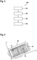
- Fig. 3 shows a method 100 according to embodiments of the invention.
- Fig. 1 illustrates a method 100 for enabling a positioning procedure, which comprises the following steps at a device 10 in a communications network 1:
- a position and an orientation of an antenna 11 is determined in relation to a reference point 51 and a reference mapping system 50 for the device 10.
- the reference point 51 of the device 10 is defined by a reference position in the reference mapping system 50.
- the orientation of the antenna 11 is mapped in relation to an orientation of the device 10.
- the orientation of the device 10 is specified by a position and an orientation information based on the reference mapping system 50.
- a message is generated.
- the message comprises the determined position 51 and the mapped orientation of the antenna 11 of the device 10.
- the message is transmitted to at least one further entity 20 in the communications network 1 to enable a positioning procedure.
- the at least one further entity 20 can comprise a node, a management function of the communications network 1, and/or a further device 20.
- Fig. 4 a schematic diagram of an embodiment of the invention is depicted.
- Fig. 4 illustrates an exemplary reference mapping system 50 according to embodiments of the invention.
- the device 10 comprises a vehicle 10.
- the spatial dimensions of the vehicle 10 such as its length, its width and its height can be defined by a reference mapping system 50.
- the reference mapping system 50 comprises a bounding box 50.
- the bounding box 50 comprises a local coordinate system x, y, z.
- the bounding box comprises a reference point 51, which as depicted in Fig. 4 is the Vehicle Reference Point 51.
- the Vehicle Reference Point (VRP) 51 is defined as a reference position in the local coordinate system of the bounding box 50.
- VRP Vehicle Reference Point
- the VRP 51 is not necessarily the center of the bounding box 50.
- the bounding box 50 is defined by its length, width, and height, together with offsets to the VRP 51 in each axis and can be represented as
- the three first elements are corresponding to the position and the last three refers to the orientation.
- the orientation information can be represented as a rotation vector using quaternions instead of yaw, pitch, roll i.e.
- a quaternion is a concept used to represent rotations and orientations in a 3D space.
- the quaternion can also be represented as a 4x1 matrix.
- the unit quaternion (a quaternion with a magnitude of 1) is commonly used to ensure mathematical stability and avoid scaling issues. This means that the sum of the squares of the four components (a, b, c, and d) of the quaternion should be equal to 1.
- These pieces of information can be sent in a message, for example in a container of a message to a further and/or surrounding entities 20 for further usage.
- Another receiving entity 20 can use the orientation information such as the antenna orientation to perform an angle of arrival (AoA) procedure. Once the position of the antenna 52 based on angle of arrival and ranging information is determined, this entity can also derive the orientation of the bounding box 50.
- Vehicles 10 are an exemplary application or use case for applying such a bounding box concept.
- the antenna orientation and bounding box concepts can be applied to any type of device 10.
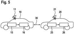
- Fig. 5 a schematic diagram of a further embodiment of the invention is shown.
- Fig. 5 depicts a vehicle 10 and a further vehicle 20.
- Each vehicle 10, 20 comprises an antenna system 11, 21 comprising a set of antennas 11, 21.
- the vehicle 10, 20 comprises a vehicle application 15, 25 and an access layer 16, 26.
- the access layer 16, 26 provides connectivity and enables communication for example via a network such as the communications network.
- Such a communication is depicted as communication link 30, which can enable communication between the vehicles 10, 20, in particular between the vehicle applications 15, 25. Therefore, as an example a message can be transmitted via the communication link 30 from the vehicle 10 to the further vehicle 20.
- the message comprises the position and the mapped orientation of the antenna 11.
- the mapped orientation of the antenna 11 can have a standardized format such as a measurement report comprising elements in a message container like for example the mapped antenna orientation information in relation to global coordinates in X, Y, Z and further coordinates like pitch, yaw, and roll, which can be transmitted as the 3D Degrees of Freedom (3DoF).
- the measurements report for conveying an antenna orientation comprise an Antenna Orientation measurement report.
- This report comprises the mapped orientation of the antenna in X, Y, Z and further pitch, yaw, and roll, and can be conveyed in a standardized RRC measurement reports targeting lower communication layers.
- This report can be transmitted periodically, or event triggered, like for example per request, if an orientation changes with a certain threshold.
- the measurements report comprises an Antenna assisting information for validating and a useability of the antenna orientation information.
- Antenna assisting information for validating and a useability of the antenna orientation information.
- This information can be transmitted with lower frequency than the orientation report or for example can be transmitted only once when positioning or beam management measurement is being considered.
- This report can be periodic, or event triggered (e.g., per request).
- the measurement report comprises an Antenna orientation measurement time stamp.
- An exact time stamp or a relative time stamp of the reported orientation measurements can be utilized for example by a receiving entity 20 such as a vehicle 20 to indicate the validity, relevance, and/or exact orientation time for a valid angle of arrival calculation.
Landscapes
- Engineering & Computer Science (AREA)
- Physics & Mathematics (AREA)
- General Physics & Mathematics (AREA)
- Radar, Positioning & Navigation (AREA)
- Remote Sensing (AREA)
- Computer Networks & Wireless Communication (AREA)
- Signal Processing (AREA)
- Mobile Radio Communication Systems (AREA)
Abstract
Description
- The invention relates to a method for enabling a positioning procedure. Furthermore, the invention relates to a transmitting and a receiving device for this purpose.
- Positioning over radio-waves has become a ubiquitous aspect of modern technology. Numerous applications rely on this well-known approach, with various systems playing crucial roles in global navigation services, object localization, and emergency phone tracking. Among these systems, GNSS (Global Navigation Satellite System) takes a vital role, while radio-based positioning and cellular communication networks also hold significant importance. The underlying principle behind most of these systems involves the utilization of time-of-flight or time-of-arrival methods. In this paradigm, anchor nodes emit a known reference signal, allowing target nodes or target devices to measure the time it takes for the signal to travel from transmission to reception. By involving enough anchor nodes, the system can calculate individual ranges and convert them into precise x, y, and z coordinates using triangulation methods. Therefore, tight synchronization requirements in positioning systems must be met to be able to precisely determine the Time Difference of Arrival (TDoA) and convert it into a physical distance. In the context of 5G positioning, angular methods are supported for network-based positioning, such as UL-AoA (Uplink Angle of Arrival) and DL-AoD (Downlink Angle of Departure) introduced in Rel. 16 and Rel. 17 of 3GPP NR-based positioning. However, the current methods may still not be sufficient to achieve the necessary level of accuracy of the positioning calculations.
- It is therefore an object of the present invention to at least partially overcome the disadvantages described above. In particular, it is an object of the present invention, to provide a method to improve the accuracy of computations for a positioning procedure and to enable more reliable positioning and orientation estimates.
- The above object is solved by a method with the features of claim 1, a Transmitting device with the features of
claim 10 and a Receiving device with the features ofclaim 11, further by a respective computer program and a computer-readable medium. Further features and details of the invention are disclosed in the respective dependent claims, the description, and the drawings. Features and details described in connection with the inventive method also apply to the inventive user equipment as well as the inventive Reduced capability user equipment, and vice versa in each case, so that with respect to the disclosure concerning the individual aspects of the invention reference can always be made mutually. - The object is particularly solved by a method for enabling a positioning procedure. The method comprises the following steps at a device, which is located in a communications network:
- Determining a position and an orientation of an antenna in relation to a reference point and/or a reference mapping system for the device, wherein the reference point of the device is defined by a reference position based on the reference mapping system,
- Mapping the orientation of the antenna in relation to an orientation of the device, wherein the orientation of the device is specified by an orientation information based on the reference mapping system,
- Generating a message comprising the determined position and the mapped orientation of the antenna of the device,
- Transmitting the message to at least one further entity in the communications network to enable a positioning procedure.
- It is possible that during the determining step the method comprises at least one of the further steps:
- Mapping the spatial dimensions of the device to the reference mapping system, wherein the spatial dimensions comprise a length, a width, and a height of the device,
- Mapping the reference position of the device to the reference mapping system, wherein the reference position is specified by a position comprising coordinates x, y, z.
- It is further possible that during the mapping step the method comprises at least one of the further steps:
- Mapping the position of the antenna to the reference position of the reference mapping system, wherein the position is specified by a coordinate and an offset in relation to the reference position of the device,
- Mapping the orientation of the antenna in relation to a horizontal plane of the reference mapping system and a direction of movement of the device.
- This mapping allows to derive the appropriate orientation coordinate information, which can be advantageously used by a further device to be able to extract and to compute the orientation information.
- It is conceivable that the message comprises an antenna orientation measurement report, wherein the antenna orientation measurement report comprises the mapped orientation of the antenna, an antenna orientation measurement time stamp, and/or antenna assisting information such as an antenna type, an antenna size and/or an antenna model or the like. It is a further possibility that the transmitting of the message is carried out periodically and/or triggered by an event such as a request.
This has the advantage that the information can be conveyed in a significantly better structured and standardized way to other entities in the communications network. Further, this enables an improved exchange of information, in particular orientation information, between these entities such as between a user equipment and a node in the communications network or between two user devices in the communications network. Furthermore, the possibility to transmit such a message or report regularly or on request improves the flexibility of distributing these reports based on the current situation in the communications network or based on the current load in the network. - It is possible that the reference mapping system for the device is based on an orientation mapping function, wherein the orientation mapping function specifies a mapping of the orientation of the antenna in relation to an orientation of the device and/or a mapping of a position of the antenna in relation to the device. This allows to combine the orientation and position data of the device more efficiently and effectively. Further this has the advantage that the orientation mapping function advantageously can completely represent the spatial state and dimensions of the device, including its 3D position and orientation. This combined output advantageously provides a better and comprehensive understanding of where the device is located in space and how it is oriented relative to a given reference system. A reference mapping system such as an orientation mapping function can be understood as a technique or mechanism, which can be used to associate the orientation or direction of a device with its position in 3D space. This function establishes a relationship between the physical orientation of the device and its spatial location. This function may comprise trigonometric calculations, matrix transformations, quaternion operations, or other mathematical techniques.
- It is possible that the reference mapping system for the device is based on a bounding box concept, wherein the bounding box specifies the reference point based on a coordinate of the bounding box and/or wherein the bounding box maps the spatial dimensions of the device in relation to a length, a width, and a height of the device. It is further possible, that the reference point (51) is based on a position in a coordinate system with a x-, y-, and/or z-axis.
The utilization of such a system allows to efficiently represent the position and size of the device in an easier or simpler way. Further, this allows to improve the mapping by representing the extents of spatial datasets, making it easier to manage and index large datasets. Furthermore, the bounding box allows to advantageously define the spatial dimensions or boundaries of devices in a simple way. A reference mapping system such as a bounding box can be defined as a geometric representation for example for a device and can be used to define the spatial boundaries or dimensions of the device. It is a kind of a virtual box that surrounds the device, and its sides are aligned with the coordinate axes (x, y, and z in 3D space). The bounding box is typically defined by its minimum and maximum coordinates along each axis. - It may be a possibility that the at least one further entity comprises a node, a management function of the communications network, and/or a further device. Transmitting the orientation information to another entity enables this entity to utilize the received information for enabling a positioning procedure such as for example for computing its relative position.
- Another aspect of the invention is a transmitting device for enabling a positioning procedure. The device comprises an antenna, a transceiver, which is connected with the antenna, a memory, and a processor. The processor is connected to the memory, the transceiver, and the antenna. The transmitting device comprises a reference mapping system of the transmitting device. The processor of the device is configured to carry out any one of the method steps of the inventive method. Thus, the transmitting device according to the invention brings the same advantages as have been described in detail with reference to the inventive method.
- Another aspect of the invention is a receiving device for enabling a positioning procedure. The receiving device is configured to carry out the following steps:
- Extracting an orientation of an antenna of a transmitting device from a message transmitted by the transmitting device according to the steps of the inventive method,
- Mapping the extracted orientation information based on an orientation mapping function of the transmitting device,
- Determining a relative position of the transmitting device based on the mapped antenna orientation.
- According to a further aspect, there is provided a computer program comprising instructions to cause
- the inventive transmitting device, or its respective embodiments, to executive the steps of the inventive method, or its respective embodiments, and/or
- the inventive receiving device to
- ∘ extract an orientation of an antenna of a transmitting device from a message transmitted by the transmitting device according to the steps of the inventive method,
- ∘ map the extracted orientation information based on an orientation mapping function of the transmitting device, and
- ∘ determine a relative position of the transmitting device based on the mapped antenna orientation.
- According to a further aspect, there is provided a computer-readable medium having stored thereon the above-mentioned computer program.
- Further advantages, features and details of the invention will be apparent from the following description, in which embodiments of the invention are described in detail with reference to the drawings. In this context, the features mentioned in the claims and in the description may each be essential to the invention individually or in any combination. Showing:
- Fig. 1
- A schematic diagram of a prior art positioning concept,
- Fig. 2
- A schematic diagram of a further prior art positioning concept,
- Fig. 3:
- A method according to embodiments of the invention,
- Fig. 4
- A schematic diagram of an embodiment of the invention,
- Fig. 5
- A schematic diagram of a further embodiment of the invention.
- In
Fig. 1 a schematic diagram of a prior art positioning procedure is shown.Fig. 1 shows a communications network 1, for example a cellular network. The communications network 1 comprisesseveral nodes 2. Eachnode 2 is communicatively connected with adevice 10 such as a user equipment depicted inFig. 1 . Further,Fig. 1 illustrates a well-known approach of a positioning procedure in the communications network 1, which is called downlink time difference of arrival (downlink TDoA). A lot of such concepts rely on so-called time-of-flight or time-of-arrival methods. Thenodes 2 or also calledanchor nodes 2 for this purpose transmit a known reference signal and the target, which inFig. 1 is depicted as auser equipment 10 measures the time between the transmission and reception of the signal. Ifenough anchor nodes 2 are involved, the individual ranges can be converted into a position in x-, y-, z-coordinates. This approach is called triangulation.
Based on this approach auser equipment 10 can be located bymultiple nodes 2 or also calledbase stations 2. - In
Fig. 2 a schematic diagram of a second prior art positioning procedure is shown, which illustrates a time-of-arrival method in relation to an uplink scenario that is based on the Uplink Time difference of arrival (TDoA) concept. In this case, theuser equipment 10 ordevice 10 sends a signal for positioning purposes to thereference nodes 2. Each reference node 2 (anchor) receives the signal transmitted by thedevice 10. Thenodes 2 have synchronized clocks to accurately timestamp when the signal arrives. Thereference nodes 2 measure the time difference of arrival (TDoA) of the signal. By comparing the arrival times of the signal atdifferent reference nodes 2, the time can be determined for the signal, which it takes to travel from thedevice 10 to eachnode 2. The TDoA measurements from thereference nodes 2 are combined and processed to calculate the time taken for the signal to reach eachnode 2 relative to a common reference time. These TDoA values are then used to determine the position of thedevice 10. Further, in addition to multiple range measurements, the number of unknowns in the positioning task can also be reduced by considering angular measurements.
In 5G positioning, angular methods can be supportive for the network-based positioning. Using a linear array, the angle of incident of a wavefront can be determined by measuring the phase offsets of the radio-waves received at each antenna. In addition to a linear array, this idea can be also applied to 2D planar antenna apertures. In this case the azimuth and elevation angle need to be determined. As a result, the time-of-flight and two angles can be determined already using only onedevice 10 and oneanchor node 2 considering angular methods. So far, linear arrays were considered, here the angular resolution depends on the number of antennas. In general, the angular resolution can be computed as:
-
Fig. 3 shows amethod 100 according to embodiments of the invention.Fig. 1 illustrates amethod 100 for enabling a positioning procedure, which comprises the following steps at adevice 10 in a communications network 1: In step 101 a position and an orientation of anantenna 11 is determined in relation to areference point 51 and areference mapping system 50 for thedevice 10. Thereference point 51 of thedevice 10 is defined by a reference position in thereference mapping system 50. Then, instep 102 the orientation of theantenna 11 is mapped in relation to an orientation of thedevice 10. The orientation of thedevice 10 is specified by a position and an orientation information based on thereference mapping system 50. At step 103 a message is generated. The message comprises thedetermined position 51 and the mapped orientation of theantenna 11 of thedevice 10. Instep 104 the message is transmitted to at least onefurther entity 20 in the communications network 1 to enable a positioning procedure. The at least onefurther entity 20 can comprise a node, a management function of the communications network 1, and/or afurther device 20. - In
Fig. 4 a schematic diagram of an embodiment of the invention is depicted.Fig. 4 illustrates an exemplaryreference mapping system 50 according to embodiments of the invention. Further, in this embodiment thedevice 10 comprises avehicle 10. The spatial dimensions of thevehicle 10 such as its length, its width and its height can be defined by areference mapping system 50. Thereference mapping system 50 comprises abounding box 50. Thebounding box 50 comprises a local coordinate system x, y, z. Further the bounding box comprises areference point 51, which as depicted inFig. 4 is theVehicle Reference Point 51. The Vehicle Reference Point (VRP) 51 is defined as a reference position in the local coordinate system of thebounding box 50. TheVRP 51 comprises the coordinates (x, y, z) = (0, 0, 0). TheVRP 51 is not necessarily the center of thebounding box 50. Thebounding box 50 is defined by its length, width, and height, together with offsets to theVRP 51 in each axis and can be represented as - BB_length
- BB_width
- BB_height
- BB_x_offset
- BB_y_offset
- BB_z_offset .
- AP_x_offset
- AP_y_offset
- AP_z_offset
- AP_roll
- AP_yaw
- AP_pitch .
- The three first elements are corresponding to the position and the last three refers to the orientation. Alternatively, the orientation information can be represented as a rotation vector using quaternions instead of yaw, pitch, roll i.e.
- AP_c
- AP_xs
- AP_ys
- AP_zs.
- A quaternion is a concept used to represent rotations and orientations in a 3D space. A quaternion is defined as a four-dimensional vector of the form:

q is the quaternion, a, b, c, and d are real numbers, and i, j, and k are the quaternion's imaginary units, each representing an axis of rotation (i for the x-axis, j for the y-axis, and k for the z-axis). The quaternion can also be represented as a 4x1 matrix. When using quaternions to represent an orientation or rotation, the unit quaternion (a quaternion with a magnitude of 1) is commonly used to ensure mathematical stability and avoid scaling issues. This means that the sum of the squares of the four components (a, b, c, and d) of the quaternion should be equal to 1.
These pieces of information can be sent in a message, for example in a container of a message to a further and/or surroundingentities 20 for further usage. Another receivingentity 20 can use the orientation information such as the antenna orientation to perform an angle of arrival (AoA) procedure. Once the position of theantenna 52 based on angle of arrival and ranging information is determined, this entity can also derive the orientation of thebounding box 50.Vehicles 10 are an exemplary application or use case for applying such a bounding box concept. The antenna orientation and bounding box concepts can be applied to any type ofdevice 10. - In
Fig. 5 a schematic diagram of a further embodiment of the invention is shown.Fig. 5 depicts avehicle 10 and afurther vehicle 20. Eachvehicle antenna system antennas vehicle vehicle application access layer access layer communication link 30, which can enable communication between thevehicles vehicle applications communication link 30 from thevehicle 10 to thefurther vehicle 20. The message comprises the position and the mapped orientation of theantenna 11. The mapped orientation of theantenna 11 can have a standardized format such as a measurement report comprising elements in a message container like for example the mapped antenna orientation information in relation to global coordinates in X, Y, Z and further coordinates like pitch, yaw, and roll, which can be transmitted as the 3D Degrees of Freedom (3DoF).
Further, the measurements report for conveying an antenna orientation comprise an Antenna Orientation measurement report. This report comprises the mapped orientation of the antenna in X, Y, Z and further pitch, yaw, and roll, and can be conveyed in a standardized RRC measurement reports targeting lower communication layers. This report can be transmitted periodically, or event triggered, like for example per request, if an orientation changes with a certain threshold.
Furthermore, the measurements report comprises an Antenna assisting information for validating and a useability of the antenna orientation information. A combination of this element is possible and advantageous with other standardized measurements associated with the orientation measurements indicating further antenna aspects assisting information such as antenna size, antenna types, or antenna shapes. This information can be transmitted with lower frequency than the orientation report or for example can be transmitted only once when positioning or beam management measurement is being considered. This report can be periodic, or event triggered (e.g., per request).
Finally, the measurement report comprises an Antenna orientation measurement time stamp. An exact time stamp or a relative time stamp of the reported orientation measurements can be utilized for example by a receivingentity 20 such as avehicle 20 to indicate the validity, relevance, and/or exact orientation time for a valid angle of arrival calculation. - The above explanation of the embodiments describes the present invention in the context of examples. Of course, individual features of the embodiments can be freely combined with each other, provided that this is technically reasonable, without leaving the scope of the present invention.
The reference point can be defined as a predefined location or position within the reference mapping system to specify various positions of the device in relation to this reference point. This point advantageously simplifies the computations in relation to positioning.
A spatial dimension of a device can be understood as a number of coordinates needed to specify the position of the device within a given reference frame. The spatial dimensions in a three-dimensional space refer to length (along the x-axis), width (along the y-axis), and height (along the z-axis).
Claims (13)
- A method (100) for enabling a positioning procedure, comprising the following steps at a device (10) in a communications network (1):- Determining (101) a position (52) and an orientation of an antenna (11) in relation to a reference point (51) and/or a reference mapping system (50) for the device (10), wherein the reference point (51) of the device (10) is defined by a reference position (51) based on the reference mapping system (50),- Mapping (102) the orientation of the antenna (11) in relation to an orientation of the device (10), wherein the orientation of the device (10) is specified by an orientation information based on the reference mapping system (50),- Generating (103) a message comprising the determined position and the mapped orientation of the antenna (11) of the device (10),- Transmitting (104) the message to at least one further entity (20) of the communications network (1) to enable a positioning procedure.
- The method (100) according to claim 1, characterized in that during the determining (102) step the method (100) comprises at least one of the further steps:- Mapping spatial dimensions of the device (10) to the reference mapping system, wherein the spatial dimensions comprise a length, a width, and a height of the device (10),- Mapping the reference position (51) of the device (10) to the reference mapping system (50), wherein the reference position (51) is specified by a position comprising coordinates x, y, z.
- The method (100) according to claim 1 or 2, characterized in that during the mapping (102) step the method (100) comprises at least one of the further steps:- Mapping the position (52) of the antenna to the reference position (51) of the reference mapping system (50), wherein the position (52) is specified by a coordinate and an offset in relation to the reference position (51) of the device (10),- Mapping the orientation of the antenna in relation to a horizontal plane of the reference mapping system (50) and a direction of movement of the device (10).
- The method (100) according to any one of the preceding claims, characterized in that the message comprises an antenna orientation measurement report, wherein the antenna orientation measurement report comprises the mapped orientation of the antenna (11), and/or an antenna orientation measurement time stamp, and/or antenna assisting information such as an antenna type, an antenna size and/or an antenna model or the like.
- The method (100) according to any one of the preceding claims, characterized in that the transmitting (104) of the message is carried out periodically and/or triggered by an event such as a request.
- The method (100) according to any one of the preceding claims, characterized in that the reference mapping system (50) for the device (10) is based on an orientation mapping function (50) , wherein the orientation mapping function (50) specifies a mapping of the orientation of the antenna in relation to an orientation of the device (10) and/or a mapping of a position of the antenna (52) in relation to the device (10).
- The method (100) according to any one of the preceding claims, characterized in that the reference mapping system (50) for the device (10) is based on a bounding box concept, wherein the bounding box (50) specifies the reference point (51) based on a coordinate of the bounding box (50) and/or wherein the bounding box (50) maps the spatial dimensions of the device (10) in relation to a length, a width, and a height of the device (10).
- The method (100) according to claim 7, characterized in that the reference point (51) is based on a position in a coordinate system with a x-, y-, and/or z-axis.
- The method (100) according to any one of the preceding claims, characterized in that the at least one further entity (20) comprises a node, a management function of the communications network, and/or a further device.
- A Transmitting device (10) for enabling a positioning procedure, comprising an antenna (11), a transceiver, which is connected with the antenna, a memory and a processor, which is connected to the memory, the transceiver and the antenna, characterized in that the transmitting device (10) comprises a reference mapping system (50) of the transmitting device (10) and that the processor of the device (10) is configured to carry out any one of the steps of the method (100) according to one of the preceding claims.
- A Receiving device (20) for enabling a positioning procedure, characterized in that the receiving device (20) is configured to carry out the following steps:- Extracting an orientation of an antenna (11) of a transmitting device (10) from a message transmitted (104) by the transmitting device (10) according to the steps of the method (100) according to one of claims 1 to 9,- Mapping the extracted orientation information based on an orientation mapping function (50) of the transmitting device (10),- Determining a relative position of the transmitting device (10) based on the mapped antenna orientation.
- A computer program comprising instructions to cause- the transmitting device (10) according to claim 10 to execute the steps of the method (100) according to one of claims 1 to 9, and/or,- the receiving device (20) according to claim 11 to∘ extract an orientation of an antenna (11) of a transmitting device (10) from a message transmitted (104) by the transmitting device (10) according to the steps of the method (100) according to one of claims 1 to 9,∘ map the extracted orientation information based on an orientation mapping function (50) of the transmitting device (10), and∘ determine a relative position of the transmitting device (10) based on the mapped antenna orientation.
- A computer-readable medium having stored thereon the computer program of claim 12.
Priority Applications (2)
| Application Number | Priority Date | Filing Date | Title |
|---|---|---|---|
| EP23190798.1A EP4506713A1 (en) | 2023-08-10 | 2023-08-10 | A method for enabling a positioning procedure |
| PCT/EP2024/072597 WO2025032226A1 (en) | 2023-08-10 | 2024-08-09 | A method for enabling a positioning procedure |
Applications Claiming Priority (1)
| Application Number | Priority Date | Filing Date | Title |
|---|---|---|---|
| EP23190798.1A EP4506713A1 (en) | 2023-08-10 | 2023-08-10 | A method for enabling a positioning procedure |
Publications (1)
| Publication Number | Publication Date |
|---|---|
| EP4506713A1 true EP4506713A1 (en) | 2025-02-12 |
Family
ID=87571430
Family Applications (1)
| Application Number | Title | Priority Date | Filing Date |
|---|---|---|---|
| EP23190798.1A Withdrawn EP4506713A1 (en) | 2023-08-10 | 2023-08-10 | A method for enabling a positioning procedure |
Country Status (2)
| Country | Link |
|---|---|
| EP (1) | EP4506713A1 (en) |
| WO (1) | WO2025032226A1 (en) |
Citations (3)
| Publication number | Priority date | Publication date | Assignee | Title |
|---|---|---|---|---|
| US20220039080A1 (en) * | 2017-08-17 | 2022-02-03 | Apple Inc. | Selecting Resources for Sidelink Communication Based on Geo-Location Information |
| WO2022034484A2 (en) * | 2020-08-10 | 2022-02-17 | Lenovo (Singapore) Pte. Ltd. | Sidelink angular-based and sl rrm-based positioning |
| US20230138181A1 (en) * | 2020-04-28 | 2023-05-04 | Huawei Technologies Co., Ltd. | Positioning information determining method and communication apparatus |
-
2023
- 2023-08-10 EP EP23190798.1A patent/EP4506713A1/en not_active Withdrawn
-
2024
- 2024-08-09 WO PCT/EP2024/072597 patent/WO2025032226A1/en active Pending
Patent Citations (3)
| Publication number | Priority date | Publication date | Assignee | Title |
|---|---|---|---|---|
| US20220039080A1 (en) * | 2017-08-17 | 2022-02-03 | Apple Inc. | Selecting Resources for Sidelink Communication Based on Geo-Location Information |
| US20230138181A1 (en) * | 2020-04-28 | 2023-05-04 | Huawei Technologies Co., Ltd. | Positioning information determining method and communication apparatus |
| WO2022034484A2 (en) * | 2020-08-10 | 2022-02-17 | Lenovo (Singapore) Pte. Ltd. | Sidelink angular-based and sl rrm-based positioning |
Also Published As
| Publication number | Publication date |
|---|---|
| WO2025032226A1 (en) | 2025-02-13 |
Similar Documents
| Publication | Publication Date | Title |
|---|---|---|
| US7170441B2 (en) | Target localization using TDOA distributed antenna | |
| EP2409535B1 (en) | Angle of arrival downlink signaling | |
| CN103096459B (en) | Method of locating user equipment and locating server | |
| CN110361692B (en) | Fusion positioning method and device | |
| US20020196188A1 (en) | System and method for determining the location of a transmitter using passive reflectors or refractors as proxy receivers and using database querying | |
| CN111417188B (en) | Terminal positioning method and device, storage medium | |
| AU2002315379A1 (en) | System and method for determining the location | |
| CN103097906A (en) | Method and apparatus for determining the position and orientation of a mobile transmitter | |
| CN106646380A (en) | Multiple-base-station spatial positioning method and multiple-base-station spatial positioning system | |
| WO2017041850A1 (en) | Fingerprint positioning for mobile terminals | |
| CN115840190A (en) | High-precision positioning method based on Bluetooth AOA and deep learning fusion | |
| CN111819457A (en) | Scaled TDOA 3D localization | |
| KR20120071291A (en) | Indoor position finding apparatus and method for measuring indoor positioning using wireless communication | |
| Fokin et al. | Topology search using dilution of precision criterion for enhanced 5G positioning service area | |
| CN101014877A (en) | Target localization using tdoa distributed antenna | |
| EP1137305A1 (en) | Method and system for locating mobile stations in a mobile communication network | |
| EP4506713A1 (en) | A method for enabling a positioning procedure | |
| US20230379715A1 (en) | System and method for detecting malicious activity in a user equipment positioning signal using a position comparator | |
| CN106257956B (en) | A kind of user facility positioning method based on Dual base stations | |
| EP4468016A1 (en) | Method of providing orientation information of a radio node of a radio network | |
| Ashraf et al. | P2P-DroneLoc: Peer-to-peer localization for GPS-denied drones using camera and WiFi fine time measurement | |
| Dinh et al. | mm-NOLOC: mmWave-based Localization for Mobile Networks without 3GPP Location Service | |
| Neuhold et al. | HiPR+: A Protocol for Centimeter 3D Localization based on UWB | |
| EP4553531A1 (en) | Probabilistic ray-tracing aided positioning | |
| EP4667960A1 (en) | Method for determining a position of a mobile device, apparatus, system, computer program product and computer-readable storage medium |
Legal Events
| Date | Code | Title | Description |
|---|---|---|---|
| PUAI | Public reference made under article 153(3) epc to a published international application that has entered the european phase |
Free format text: ORIGINAL CODE: 0009012 |
|
| STAA | Information on the status of an ep patent application or granted ep patent |
Free format text: STATUS: THE APPLICATION HAS BEEN PUBLISHED |
|
| AK | Designated contracting states |
Kind code of ref document: A1 Designated state(s): AL AT BE BG CH CY CZ DE DK EE ES FI FR GB GR HR HU IE IS IT LI LT LU LV MC ME MK MT NL NO PL PT RO RS SE SI SK SM TR |
|
| STAA | Information on the status of an ep patent application or granted ep patent |
Free format text: STATUS: REQUEST FOR EXAMINATION WAS MADE |
|
| 17P | Request for examination filed |
Effective date: 20250812 |
|
| STAA | Information on the status of an ep patent application or granted ep patent |
Free format text: STATUS: THE APPLICATION IS DEEMED TO BE WITHDRAWN |
|
| 18D | Application deemed to be withdrawn |
Effective date: 20250813 |