EP4506657A1 - Detection device for detecting defect of electrode and operation method thereof - Google Patents
Detection device for detecting defect of electrode and operation method thereof Download PDFInfo
- Publication number
- EP4506657A1 EP4506657A1 EP23879977.9A EP23879977A EP4506657A1 EP 4506657 A1 EP4506657 A1 EP 4506657A1 EP 23879977 A EP23879977 A EP 23879977A EP 4506657 A1 EP4506657 A1 EP 4506657A1
- Authority
- EP
- European Patent Office
- Prior art keywords
- electrode
- detection device
- thickness
- processor
- various embodiments
- Prior art date
- Legal status (The legal status is an assumption and is not a legal conclusion. Google has not performed a legal analysis and makes no representation as to the accuracy of the status listed.)
- Pending
Links
Images








Classifications
-
- G—PHYSICS
- G01—MEASURING; TESTING
- G01B—MEASURING LENGTH, THICKNESS OR SIMILAR LINEAR DIMENSIONS; MEASURING ANGLES; MEASURING AREAS; MEASURING IRREGULARITIES OF SURFACES OR CONTOURS
- G01B11/00—Measuring arrangements characterised by the use of optical techniques
- G01B11/02—Measuring arrangements characterised by the use of optical techniques for measuring length, width or thickness
- G01B11/06—Measuring arrangements characterised by the use of optical techniques for measuring length, width or thickness for measuring thickness ; e.g. of sheet material
-
- G—PHYSICS
- G01—MEASURING; TESTING
- G01B—MEASURING LENGTH, THICKNESS OR SIMILAR LINEAR DIMENSIONS; MEASURING ANGLES; MEASURING AREAS; MEASURING IRREGULARITIES OF SURFACES OR CONTOURS
- G01B21/00—Measuring arrangements or details thereof, where the measuring technique is not covered by the other groups of this subclass, unspecified or not relevant
- G01B21/02—Measuring arrangements or details thereof, where the measuring technique is not covered by the other groups of this subclass, unspecified or not relevant for measuring length, width, or thickness
- G01B21/08—Measuring arrangements or details thereof, where the measuring technique is not covered by the other groups of this subclass, unspecified or not relevant for measuring length, width, or thickness for measuring thickness
-
- H—ELECTRICITY
- H01—ELECTRIC ELEMENTS
- H01M—PROCESSES OR MEANS, e.g. BATTERIES, FOR THE DIRECT CONVERSION OF CHEMICAL ENERGY INTO ELECTRICAL ENERGY
- H01M10/00—Secondary cells; Manufacture thereof
- H01M10/05—Accumulators with non-aqueous electrolyte
- H01M10/058—Construction or manufacture
- H01M10/0585—Construction or manufacture of accumulators having only flat construction elements, i.e. flat positive electrodes, flat negative electrodes and flat separators
-
- H—ELECTRICITY
- H01—ELECTRIC ELEMENTS
- H01M—PROCESSES OR MEANS, e.g. BATTERIES, FOR THE DIRECT CONVERSION OF CHEMICAL ENERGY INTO ELECTRICAL ENERGY
- H01M10/00—Secondary cells; Manufacture thereof
- H01M10/42—Methods or arrangements for servicing or maintenance of secondary cells or secondary half-cells
- H01M10/48—Accumulators combined with arrangements for measuring, testing or indicating the condition of cells, e.g. the level or density of the electrolyte
-
- H—ELECTRICITY
- H01—ELECTRIC ELEMENTS
- H01M—PROCESSES OR MEANS, e.g. BATTERIES, FOR THE DIRECT CONVERSION OF CHEMICAL ENERGY INTO ELECTRICAL ENERGY
- H01M4/00—Electrodes
- H01M4/02—Electrodes composed of, or comprising, active material
- H01M4/04—Processes of manufacture in general
-
- Y—GENERAL TAGGING OF NEW TECHNOLOGICAL DEVELOPMENTS; GENERAL TAGGING OF CROSS-SECTIONAL TECHNOLOGIES SPANNING OVER SEVERAL SECTIONS OF THE IPC; TECHNICAL SUBJECTS COVERED BY FORMER USPC CROSS-REFERENCE ART COLLECTIONS [XRACs] AND DIGESTS
- Y02—TECHNOLOGIES OR APPLICATIONS FOR MITIGATION OR ADAPTATION AGAINST CLIMATE CHANGE
- Y02E—REDUCTION OF GREENHOUSE GAS [GHG] EMISSIONS, RELATED TO ENERGY GENERATION, TRANSMISSION OR DISTRIBUTION
- Y02E60/00—Enabling technologies; Technologies with a potential or indirect contribution to GHG emissions mitigation
- Y02E60/10—Energy storage using batteries
Definitions
- Various embodiments disclosed herein relate to a detection device configured to detect a bad electrode and a method of operating the same, and more specifically, to a technology for detecting a bad electrode capable of causing the formation of a gap in a coupling surface with a separator.
- Such a secondary battery is manufactured in a form in which an electrode assembly composed of a cathode, a separator, and an anode is accommodated in a battery case together with an electrolyte solution.
- the electrode assembly may be manufactured by laminating the cathode and the anode in a state in which the separator is interposed therebetween, and then applying a certain level of heat and a pressure.
- a portion in which the electrode and the separator face each other may be accommodated in the battery case in a state of being coupled (e.g., bonded) by heat and the pressure.
- a coupling state between an electrode and a separator in an electrode assembly is related to the performance of a secondary battery. For example, when a portion (e.g., a coupling surface) in which the electrode and the separator face each other has a uniform thickness, it is possible to ensure the performance of the secondary battery at a certain level. Conversely, when at least a portion of the portion in which the electrode and the separator face each other has a non-uniform thickness due to a weakened bonding strength or the like, it is not possible to ensure the performance of the secondary battery at the certain level.
- consumption of an electrolyte solution may increase due to a high resistance, thereby causing swelling of a battery cell and causing degradation in the performance of the secondary battery due to lithium precipitation.
- At least one of various embodiments of the present invention is directed to providing a detection device configured to detect a bad electrode capable of causing the degradation in the performance of the secondary battery and a method of operating the same.
- At least one of various embodiments of the present invention is directed to providing a detection device configured to detect a bad electrode capable of causing the formation of a gap (e.g., a space) in an electrode assembly based on a thickness change of an electrode and a method of operating the same.
- a detection device configured to detect a bad electrode capable of causing the formation of a gap (e.g., a space) in an electrode assembly based on a thickness change of an electrode and a method of operating the same.
- a detection device configured to detect a bad electrode includes a measurement module configured to acquire a thickness measurement value of at least one electrode, and a processor electrically connected to the measurement module, wherein the processor is configured to check a groove formed in the at least one electrode based on the thickness measurement value, and detect the at least one electrode as a bad electrode when a wave-shaped groove corresponding to a reference shape is checked.
- the processor may be configured to check the wave-shaped groove in a form in which a plateau area increased to a certain level or more compared to a reference thickness and a dip area decreased to a certain level or less compared to the reference thickness are consecutively formed based on the reference thickness for the at least one electrode.
- the reference shape may include at least one of a specified area and a specified depth.
- the processor may be configured to check the groove, which is formed in the at least one electrode, in an inclined portion of which a thickness gradually decreases.
- the inclined portion may be formed in a cutting or coating process among processes of manufacturing the at least one electrode.
- the processor may be configured to check the groove in an upper end portion of the electrode in a certain range toward the other end based on an edge of an electrode tab formed on the at least one electrode.
- the processor may be configured to acquire a thickness measurement value of an electrode assembly in which a cathode and an anode having substantially the same size are laminated with a separator interposed therebetween.
- the processor may be configured to acquire a thickness measurement value of an electrode assembly in which an anode having a relatively larger size and a cathode having a relatively smaller size are laminated with a separator interposed therebetween.
- the processor may be configured to check a distance between a position at which the dip area starts after the plateau area and an edge of the cathode when the wave-shaped groove corresponding to the reference shape is checked, detect the at least one electrode as a normal electrode when the distance is included in a specified range, and detect the at least one electrode as a bad electrode when the distance is out of the specified range.
- the detection device may further include a memory, wherein the processor may be configured to re-set the reference shape based on the shape of the wave-shaped groove formed in the bad electrode, and store the re-set reference shape in the memory.
- a method of operating the detection device includes an operation of acquiring a thickness measurement value of at least one electrode, an operation of checking a groove formed in the at least one electrode based on the thickness measurement value, and an operation of detecting the at least one electrode as a bad electrode when a wave-shaped groove corresponding to a reference shape is checked.
- the wave-shaped groove may include a form in which a plateau area increased to a certain level or more compared to a reference thickness and a dip area decreased to a certain level or less compared to the reference thickness are consecutively formed based on the reference thickness for the at least one electrode.
- the reference shape may include at least one of a specified area and a specified depth.
- the operating method may include an operation of checking the groove, which is formed in the at least one electrode, in an inclined portion of which a thickness gradually decreases.
- the inclined portion may be formed in a cutting or coating process among processes of manufacturing the at least one electrode.
- the operating method may include an operation of checking the groove in an upper end portion of the electrode in a certain range toward the other end based on an edge of an electrode tab formed on the at least one electrode.
- the operating method may include an operation of acquiring a thickness measurement value of an electrode assembly in which a cathode and an anode having substantially the same size are laminated with a separator interposed therebetween.
- the operating method may include an operation of acquiring a thickness measurement value of an electrode assembly in which an anode having a relatively larger size and a cathode having a relatively smaller size are laminated with a separator interposed therebetween.
- the operating method may include an operation of checking a distance between a position at which the dip area starts after the plateau area and an edge of the cathode when the wave-shaped groove corresponding to the reference shape is checked, an operation of detecting the at least one electrode as a normal electrode when the distance is included in a specified range, and an operation of detecting the at least one electrode as a bad electrode when the distance is out of the specified range.
- the operating method may include an operation of re-setting the reference shape based on the shape of the wave-shaped groove formed in the bad electrode, and an operation of storing the re-set reference shape.
- the detection device configured to detect the failure of the electrode and the method of operating the same according to various embodiments disclosed herein, by detecting the bad electrode capable of causing the formation of the gap in the electrode assembly based on the thickness change of the electrode, it is possible to manufacture the secondary battery that ensures the performance at the certain level.
- first, second, A, B, (a), and (b) may be used to describe components of the embodiments of the present invention. These terms are only for the purpose of distinguishing one component from another, and the nature, sequence, order, or the like of the corresponding component is not limited by the terms.
- all terms (including technical and scientific terms) used herein have the same meanings as those commonly understood by those skilled in the art to which the present invention pertains.
- the terms defined in a generally used dictionary should be construed as having meanings that coincide with the meanings of the terms from the context of the related technology and are not construed as an ideal or excessively formal meaning unless clearly defined in this document.
- each of phrases such as “A or B,” “at least one of A and B,” “at least one of A or B,” “A, B, or C,” “at least one of A, B, and C,” and “at least one of A, B, or C” may include any one of the items listed together in the corresponding phrase among these phrases or all possible combinations thereof.
- the terms such as “first,” “second,” “first,” or “second” may simply be used to distinguish the corresponding component from another and do not limit the corresponding components in another aspect (e.g., importance or order).
- a certain component e.g., a first component
- another component e.g., a second component
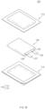
- FIGS. 1A to 1C are views schematically illustrating a secondary battery according to various embodiments.
- a secondary battery 100 may be configured in a form in which an electrode assembly 120 and an electrolyte solution are accommodated in a battery case 110.
- the battery case 110 may include a first case 112 (e.g., an upper case) and a second case 114 (e.g., a lower case).
- the first case 112 may include a space configured to accommodate at least a portion of the electrode assembly 120
- the second case 114 may include a space configured to accommodate the other portion of the electrode assembly 120.
- the electrode assembly 120 and the electrolyte solution may be accommodated in an inner space formed by coupling the first case 112 to the second case 114, and edges of the first case 112 and the second case 114 may be sealed in a state in which the electrode assembly 120 and the electrolyte solution are accommodated.
- the electrode assembly 120 may be configured in a form in which a first electrode 122 (e.g., an anode or a negative electrode plate) and a second electrode 125 (e.g., a cathode or a positive electrode plate) are laminated with a separator 121 interposed therebetween.
- a first electrode 122 e.g., an anode or a negative electrode plate
- a second electrode 125 e.g., a cathode or a positive electrode plate
- each of the electrodes 122 and 125 may be formed in a structure in which an active material slurry is applied to a current collector.
- the slurry may be formed by stirring a granular active material, an auxiliary conductor, a binder, a plasticizer, or the like in a state in which a solvent is added.
- each of the electrodes 122 and 125 may have a non-coated portion to which the slurry is not applied, and an electrode tab 123 or 126 corresponding to each of the electrodes 122 and 125 may be attached to the non-coated portion.
- each of the electrode tabs 123 and 126 may be coupled by being attached to one end of an electrode lead 124 or 127, and the other end of the electrode lead 124 or 127 may be exposed to the outside of the battery case 110 and provided as an electrode terminal that may be connected to another secondary battery or an external device such as a load or a charging device.
- each of the electrodes 122 and 125 and the separator 121 may be maintained as a state of being coupled (e.g., bonded) by heat and a pressure in the electrode assembly 120, and in order to ensure the performance of the secondary battery 100 at a certain level, each of the electrodes 122 and 125 and the separator 121 need to be coupled to form a coupling surface (e.g., a bonding surface) having an uniform thickness.
- a coupling surface e.g., a bonding surface
- consumption of the electrolyte solution in the electrode assembly 120 may increase in a portion of the coupling surface having a non-uniform thickness, thereby causing swelling of a battery cell and causing degradation in the performance of the secondary battery 100 due to lithium precipitation.
- At least one of the electrode 122 and 125 that cause a state of the non-uniform thickness when coupled to the separator 121 may be detected. Therefore, since the electrodes 122 and 125 that cause the state of the non-uniform thickness when coupled to the separator 121 may be detected before or after the electrode assembly 120 is manufactured, it is possible to manufacture the secondary battery 100 that ensures performance at a certain level.
- a detection device configured to detect a failure of the electrodes 122 and 125 according to various embodiments will be described in detail with reference to FIGS. 2 to 6 below.
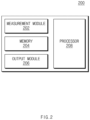
- FIG. 2 is a view illustrating a configuration of a detection device configured to detect a failure of an electrode according to various embodiments.
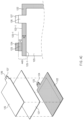
- FIGS. 3A and 3B are views for describing a bad electrode that causes the formation of a gap in an electrode assembly
- FIGS. 4A to 4D are views for describing an operation of detecting the bad electrode according to various embodiments
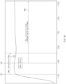
- FIG. 5 is a view for describing another operation of detecting the bad electrode according to various embodiments.
- a detection device 200 may include a measurement module 202, a memory 204, an output module 206, and a processor 208.
- this is only exemplary, and various embodiments are not limited thereto.
- at least one of components of the detection device 200 may be omitted, or one or more other components (e.g., an input device or a power management device) may be added as components of the detection device 200.
- at least one of the above-described components may be integrated with another component.
- the measurement module 202 may be configured to acquire a thickness measurement value for at least one of the electrodes 122 and 125. According to one embodiment, the measurement module 202 may measure the thickness measurement value for the at least one of the electrodes 122 and 125 coupled to the separator 121.
- the measurement module 202 may include a light emitter configured to emit light toward the at least one of the electrodes 122 and 125 and a light receiver configured to detect light reflected from the at least one of the electrodes 122 and 125.
- the memory 204 may include programs, algorithms, routines, and/or commands related to an operation (or control) of the detection device 200.
- the memory 204 may include at least one type of storage medium among a memory of a flash memory type, a hard disk type, a micro type, or a card type (e.g., a secure digital (SD) card or an extream digital (XD) card), and a memory of a random access memory (RAM), static RAM (SRAM), read-only memory (ROM), programmable ROM (PROM), electrically erasable PROM (EEPROM), magnetic RAM (MRAM), magnetic disk, or optical disk type, and various embodiments are not limited thereto.
- a memory of a flash memory type e.g., a secure digital (SD) card or an extream digital (XD) card
- RAM random access memory
- SRAM static RAM
- ROM read-only memory
- PROM programmable ROM
- EEPROM electrically erasable PROM
- MRAM magnetic RAM
- the output module 206 may provide information on the operation of the detection device 200.
- at least a portion of the information output through the output module 206 may include a result of detecting at least one of the electrodes 122 and 125 (e.g., a bad electrode) that causes the non-uniform thickness when coupled to the separator 121.
- the output module 206 may include a display configured to output visual information.
- the display may include one or more among a liquid crystal display, a thin film transistor-liquid crystal display, an organic light-emitting diode, a flexible display, a 3-dimensional (3D) display, and a transparent display.
- the display 120 may include a touch sensor configured to detect a touch.
- the output module 206 may further include an audio output device (e.g., a speaker) configured to output an audio signal to the outside of the detection device 200).
- an audio output device e.g., a speaker
- the processor 208 may control one or more other components (e.g., the measurement module 202, the memory 204, and the output module 206) of the detection device 200 and perform various data processing or calculations.
- the processor 208 may control one or more other components (e.g., the measurement module 202, the memory 204, and the output module 206) of the detection device 200 and perform various data processing or calculations.
- the processor 208 may detect at least one of the electrodes 122 and 125 that causes the non-uniform thickness when coupled to the separator 121. As described above, when the coupling surface formed by coupling the at least one of the electrodes 122 and 125 to the separator 121 has a non-uniform thickness, it is possible to degrade the performance of the secondary battery 100.
- the thickness of the coupling surface may be determined by a shape of the at least one of the electrodes 122 and 125. For example, as illustrated in FIGS. 3A and 3B , when at least one of the electrodes 122 and 125 in which an area (e.g., a groove) 310 relatively dipped compared to the periphery is formed is coupled to the separator 121, this may cause the formation of a gap (e.g., a space) 320 having a certain size in a portion (e.g., a coupling surface) in which the at least one of the electrodes 122 and 125 and the separator 121 face each other. According to one embodiment, as illustrated in FIG.
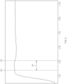
- the groove 310 may be a wave-shaped groove including a form in which an area 402 (e.g., a plateau area) increased to a certain level or more compared to a reference thickness 401 (e.g., an average thickness) and an area 404 (e.g., a dip area) decreased to a certain level or less compared to the reference thickness 401 are consecutively formed based on the reference thickness 401 (e.g., the average thickness) of surfaces of the electrodes 122 and 125.
- an area 402 e.g., a plateau area
- a reference thickness 401 e.g., an average thickness
- an area 404 e.g., a dip area
- the gap 320 formed by the wave-shaped groove 310 is a portion in which at least a portion of the electrode 122 or 125 and at least a portion of the separator 121 are not coupled by a weakened coupling strength (e.g., a bonding strength) around the groove 310 formed in the electrode 122 or 125 and may cause the formation of the coupling surface having the non-uniform thickness.
- a weakened coupling strength e.g., a bonding strength
- the processor 208 may detect at least one of the electrodes 122 and 125 having the shape in which the groove 310 (e.g., the wave-shaped groove) is formed as a bad electrode that causes the formation of the gap 320 in the electrode assembly 120 when coupled to the separator 120. Therefore, it is possible to prevent the electrode assembly 120 from being manufactured as the bad electrode, and as a result, it is possible to manufacture the secondary battery 100 that ensures the performance at a certain level.
- the processor 208 according to various embodiments related to this will be described in detail below.
- the processor 208 may check a thickness change of the at least one of the electrodes 122 and 125 as part of the operation of detecting the bad electrode. For example, the processor 208 may measure the thickness (e.g., the thickness change) of the at least one of the electrodes 122 and 125 based on measurement values acquired through the measurement module 202.
- the processor 208 may determine whether the groove 310 relatively dipped compared to the periphery has been formed in the at least one of the electrodes 122 and 125 based on the measured thickness.
- the processor 208 may determine whether the wave-shaped groove in which the area 402 (e.g., the plateau area) increased to the certain level or more compared to the reference thickness 401 and the area 404 (e.g., the dip area) decreased to the certain level or less compared to the reference thickness 401 are consecutively formed based on the reference thickness 401 (e.g., the average thickness) of the surfaces of the electrodes 122 and 125 has been formed.
- the processor 208 may determine that the groove 310 is not formed in the corresponding electrode when the thickness of the at least one of the electrodes 122 and 125 is changed in the same direction (or to the same sign).
- the processor 208 may determine that at least one groove 310 has been formed in the corresponding electrode when an inflection point at which a direction of the thickness change of the at least one of the electrodes 122 and 125 is changed is present.
- the processor 208 may determine whether the checked groove 310 may cause the formation of the gap 320 in the electrode assembly 120 when the at least one of the electrodes 122 and 125 and the separator 120 are coupled. For example, the processor 208 may determine that the groove 310 having a specified size and/or a specified depth formed in the at least one of the electrodes 122 and 125 may cause the formation of the gap 320.
- the processor 208 may determine a depth of the groove 310 based on a difference 420 between a maximum value 422 corresponding to a largest thickness of a measurement target (e.g., a maximum thickness of the plateau area) and a minimum value 424 corresponding to a smallest thickness of the measurement target (e.g., a minimum thickness of the dig area) among measured values 410 acquired through the measurement module 202.
- the processor 208 may determine a size of the groove 310 based on a range in which the measured values corresponding to a thickness smaller than or equal to a certain level are consecutively acquired.
- this is only exemplary, and various embodiments are not limited thereto.
- various known techniques may be applied to determine the size and/or depth of the groove 310 formed in the at least one of the electrodes 122 and 125.
- the at least one of the electrodes 122 and 125 may be defined as having a body portion and an upper end portion.
- the upper end portion may be defined as an area in a certain range toward the other end based on an edge of the electrode 122 or 125 (e.g., an edge of the electrode tab 124 or 127).
- the body portion may be defined as the remaining area excluding the upper portion of the electrode 122 or 125.
- the groove 310 that causes the formation of the gap 320 in the electrode assembly 120 is relatively more likely to be formed in the upper end portion than in the body portion of the electrode 122 or 125.
- the processor 208 may restrict a determination area in which whether the groove 310 is formed is determined to the upper end portion of the electrode 122 or 125.
- the electrode assembly 120 may be configured in a form in which the anode 122 and the cathode 125 having substantially the same size are laminated with the separator 121 interposed therebetween.
- the processor 208 may restrict an upper end portion 430 in a certain range d toward the other end based on an edge 431 of the electrode tab 123 or 126 to the determination area.
- the processor 208 may omit an operation of determining whether the groove 310 is formed in the body portion of the electrode 122 or 125 excluding the determination area.
- this is only exemplary, and various embodiments are not limited thereto.
- the operation of determining whether the groove 310 is formed may be performed on only the body portion of the electrode 122 or 125 or may be performed on all of the upper portion and the body portion.
- the electrode assembly 120 may be configured in a form in which the anode 122 and the cathode 125 having different sizes are laminated with the separator 121 interposed therebetween.
- the processor 208 may restrict an upper portion 440 in which the two electrodes 122 and 125 do not face each other to the determination area.
- the processor 208 may determine whether the groove 310 is formed in only a determination area (A+B) including an area A between an edge 122-1 of the first electrode (e.g., the anode 122) having a relatively larger size and an edge 123-1 of the electrode tab 123 and an area B between the edge 122-1 of the first electrode and an edge 125-1 of the second electrode 125 having a relatively smaller size.
- A+B determination area
- an inclined portion may be formed on the upper end portion of the electrode 122 or 125.
- the inclined portion of which a thickness gradually decreases toward the edge of the electrode 122 or 125 without cutting the edge of the electrode 122 or 125 (e.g., the edge 122-1 of the first electrode 122) substantially at a right angle may be formed.
- an inclined portion in which a thickness of a slurry decreases toward the edge of the electrode 122 or 125 may be formed.
- the processor 208 may define a range in which the maximum value corresponding to the largest thickness of the measurement target is acquired and a range in which the minimum value corresponding to the smallest thickness of the measurement target is acquired based on the inclined portion.
- the processor 208 may define a boundary 452 (e.g., the edge 125-1 of the second electrode 125 illustrated in FIG. 4C ) between the body portion and the upper end portion of the electrode 122 or 125 as a determination start point and define a certain range from the determination start point as a maximum value calculation range 454 (e.g., a plateau area detection range).
- the maximum value calculation range 454 may be a range of 2 mm to 5 mm from the determination start point.
- a range within 3 mm from the determination start point may be the maximum value calculation range.
- the processor 208 may define a certain range from a maximum value calculation point 456 as a minimum value calculation range 458 (e.g., a dig area detection range).
- a minimum value calculation range 458 may be a range from 8 mm to 15 mm from the maximum value calculation point 456.
- a range within 10 mm from the maximum value calculation point 456 may be the minimum value calculation range.
- the processor 208 may detect the bad electrode based on the groove 310 formed in the electrode 122 or 125.
- the processor 208 may further consider a position of the groove 310 when detecting the bad electrode. For example, as the position at which the groove 310 is formed is closer to the boundary 452 (e.g., the edge 125-1 of the second electrode 125 illustrated in FIG. 4C ) between the body portion and the upper end portion of the electrode 122 or 125, the gap 320 having a relatively smaller size may be formed.
- the processor 208 may determine the corresponding electrode in which the groove 310, which may cause the formation of the gap 320 in the electrode assembly 120, is formed to be a normal electrode when a distance 514 between a boundary 510 (e.g., the edge 125-1 of the second electrode 125 illustrated in FIG. 4C ) between the body portion and the upper end portion of the electrode 122 or 125 and a position 512 at which the groove is formed corresponds to a specified range.
- the processor 208 may check the distance 514 between the edge of the plateau area, that is, the portion 512 at which the dip area starts and the boundary 510 between the body portion and the upper end portion.
- the portion 512 at which the dip area starts may be defined in a range of 5% of a depth of the dip area.
- the distance 514 between the portion 512 at which the dip area starts and the boundary 510 between the body portion and the upper end portion, which is illustrated in FIG. 5 may be defined as a width of the plateau area.
- an electrode in which a plateau area having a width in a specified range and a dip area are consecutively formed may be determined to be a normal electrode.
- an electrode in which a plateau area having a width exceeding the specified range and a dip area are consecutively formed may be determined to be a bad electrode.
- FIGS. 6A and 6B are views for describing the performance of the detection device according to various embodiments.
- the gap 320 may be formed in the electrode assembly 120 by at least one of the electrodes 122 and 125.
- FIG. 6A is a view illustrating the relationship between shapes of target electrodes and a gap.
- a third target electrode (case 3) 605 is a reference electrode that becomes a reference for a quality requirement. It can be seen that a shape of a first target electrode (case 1) 601 has a shape in which a thickness gradually decreases with a decreasing width similar to that of the third target electrode 605. Similar to a thickness change 615 of the third target electrode 605, this means that a thickness 611 of the first target electrode 601 without an inflection point in which a direction of the thickness change is changed may be detected as a thickness of a normal electrode that does not cause the formation of the gap.
- a shape of a second target electrode (case 2) 603 has a shape in which a thickness decreases with a decreasing width different from that of the third target electrode 605. Differently from the thickness change 615 of the third target electrode 605, this means that the thickness 613 of the second target electrode 603 with the inflection point in which the direction of the thickness change is changed may be detected as a thickness of a bad electrode that causes the formation of the gap.
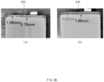
- FIG. 6B is a view illustrating the electrode assembly 120 formed of target electrodes and illustrates that the detection result of FIG. 6A is very accurate.
- FIG. 6B illustrates the electrode assembly 120 manufactured by using the first target electrode 601 detected as the normal electrode, and a gap 620 having a relatively smaller size is formed between the first target electrode 601 and the separator 121.
- FIG. 6B illustrates the electrode assembly 120 manufactured by using the second target electrode 603 detected as the bad electrode, and a gap 630 having a relatively larger size is formed between the second target electrode 603 and the separator 121.
- the detection device 200 may accurately detect the bad electrode that may cause the formation of the gap in the electrode assembly 120 based on the thickness change of the electrode 122 or 125.
- FIG. 7 is a flowchart for describing a detection operation of the detection device according to various embodiments.
- Each operation in the following embodiment may be performed sequentially, but is not necessarily performed sequentially. For example, the order of each operation may be changed, and at least two operations may be performed in parallel. In addition, at least one of the following operations may be omitted according to embodiments.
- the detection device 200 may measure the thickness of the anode 122 coupled to the cathode 124 in operation 710. According to one embodiment, as illustrated in FIG. 4C , the detection device 200 may measure the thickness of the anode 122 in a state in which the anode 122 having a relatively larger size and the cathode 124 having a relatively smaller size are laminated with the separator 121 interposed therebetween.
- the detection device 200 may determine whether the gap 320 is formed in the coupling area based on the measured thickness. According to one embodiment, the detection device 200 may determine whether the anode 122 has a shape that causes the formation of the gap 320. For example, the detection device 122 may check whether the groove 310 having the specified depth and/or size has been formed based on the thickness change of the anode 122.
- the detection device 200 may determine whether the wave-shaped groove in which the area 402 (e.g., the plateau area) increased to the certain level or more compared to the reference thickness 401 and the area 404 (e.g., the dip area) decreased to the certain level or less compared to the reference thickness 401 are consecutively formed based on the reference thickness 401 (e.g., the average thickness) of the surfaces of the electrodes 122 and 125 has been formed.
- the area 402 e.g., the plateau area
- the area 404 e.g., the dip area
- the detection device 200 may determine a failure of the anode 122 based on a result of determining whether the gap 320 is formed. According to one embodiment, the detection device 200 may determine the anode 122 in which the groove 310 having the specified depth and/or size has been formed to be the bad anode.
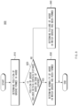
- FIG. 8 is a flowchart for describing another operation of the detection device according to various embodiments Operations of FIG. 8 to be described below may be those representing various embodiments of operation 730 in FIG. 7 .
- the detection device may determine the position of the groove 310 formed in the anode 200 (e.g., the processor 208).
- the detection device 200 may determine whether the position of the groove 310 is within a certain distance based on the edge of the cathode 124.
- the detection device 200 e.g., the processor 208 may determine the anode 122 in which the groove 310 has been formed to be a normal anode.
- the detection device 200 may determine the anode 122 in which the groove 310 has been formed to be a bad anode.
- FIGS. 9A and 9B are views for describing an operation of setting a quality requirement criterion for an electrode in the detection device according to various embodiments.
- the detection device 200 may set a quality requirement criterion based on a result of determining a quality (or an analysis result) of the electrode 122 or 125.
- the detection device 200 may store the result of determining the quality of the electrode 122 or 125 in the form of a table.
- the detection device 200 may store the shape of the groove 310 formed in the electrode 122 or 125 determined to be normal.
- the shape of the groove 310 may include at least one of the formation position of the groove 310, the area of the groove 310, and the depth of the groove 310.
- the detection device 200 may store a shape of the plateau area and a shape of the dip area.
- the detection device 200 may set an approximate value 910 of the stored shape of the groove to a criterion for determining normality. For example, as illustrated in FIG. 9B , a range of the groove 310 that may be determined to be normal may be specified 920 based on the shape of the groove 310 checked on the normal electrode. This criterion may be updated each time the quality requirement determination operation is performed. Therefore, the detection device 200 may determine an electrode in which the groove 310 included in a specified range has been formed to be the normal electrode and determine an electrode in which the groove 310 not included in the specified range has been formed to be the bad electrode.
- the detection device 200 may set the criterion for determining normality based on the result of determining the normality of the electrode 122 or 125.
- this is only exemplary, and various embodiments are not limited thereto.
- the detection device 200 may store the shape of the groove 310 formed in the electrode 122 or 125 determined to be bad and set an approximate value of the stored shape of the groove 310 to a criterion for determining a failure.
Landscapes
- Physics & Mathematics (AREA)
- General Physics & Mathematics (AREA)
- Engineering & Computer Science (AREA)
- Manufacturing & Machinery (AREA)
- Chemical & Material Sciences (AREA)
- Chemical Kinetics & Catalysis (AREA)
- Electrochemistry (AREA)
- General Chemical & Material Sciences (AREA)
- Secondary Cells (AREA)
- Battery Electrode And Active Subsutance (AREA)
Abstract
Description
- This application claims priority to and the benefit of
Korean Patent Application No. 10-2022-0134436 - Various embodiments disclosed herein relate to a detection device configured to detect a bad electrode and a method of operating the same, and more specifically, to a technology for detecting a bad electrode capable of causing the formation of a gap in a coupling surface with a separator.
- Recently, secondary batteries are being increasingly developed and used due to an advantage that they are rechargeable and have a smaller size and a larger capacity.
- Such a secondary battery is manufactured in a form in which an electrode assembly composed of a cathode, a separator, and an anode is accommodated in a battery case together with an electrolyte solution. For example, the electrode assembly may be manufactured by laminating the cathode and the anode in a state in which the separator is interposed therebetween, and then applying a certain level of heat and a pressure. In this case, a portion in which the electrode and the separator face each other may be accommodated in the battery case in a state of being coupled (e.g., bonded) by heat and the pressure.
- In general, a coupling state between an electrode and a separator in an electrode assembly is related to the performance of a secondary battery. For example, when a portion (e.g., a coupling surface) in which the electrode and the separator face each other has a uniform thickness, it is possible to ensure the performance of the secondary battery at a certain level. Conversely, when at least a portion of the portion in which the electrode and the separator face each other has a non-uniform thickness due to a weakened bonding strength or the like, it is not possible to ensure the performance of the secondary battery at the certain level. For example, in the case of a portion of the coupling surface having a non-uniform thickness, consumption of an electrolyte solution may increase due to a high resistance, thereby causing swelling of a battery cell and causing degradation in the performance of the secondary battery due to lithium precipitation.
- At least one of various embodiments of the present invention is directed to providing a detection device configured to detect a bad electrode capable of causing the degradation in the performance of the secondary battery and a method of operating the same.
- At least one of various embodiments of the present invention is directed to providing a detection device configured to detect a bad electrode capable of causing the formation of a gap (e.g., a space) in an electrode assembly based on a thickness change of an electrode and a method of operating the same.
- A detection device configured to detect a bad electrode according to various embodiments includes a measurement module configured to acquire a thickness measurement value of at least one electrode, and a processor electrically connected to the measurement module, wherein the processor is configured to check a groove formed in the at least one electrode based on the thickness measurement value, and detect the at least one electrode as a bad electrode when a wave-shaped groove corresponding to a reference shape is checked.
- According to various embodiments, the processor may be configured to check the wave-shaped groove in a form in which a plateau area increased to a certain level or more compared to a reference thickness and a dip area decreased to a certain level or less compared to the reference thickness are consecutively formed based on the reference thickness for the at least one electrode.
- According to various embodiments, the reference shape may include at least one of a specified area and a specified depth.
- According to various embodiments, the processor may be configured to check the groove, which is formed in the at least one electrode, in an inclined portion of which a thickness gradually decreases.
- According to various embodiments, the inclined portion may be formed in a cutting or coating process among processes of manufacturing the at least one electrode.
- According to various embodiments, the processor may be configured to check the groove in an upper end portion of the electrode in a certain range toward the other end based on an edge of an electrode tab formed on the at least one electrode.
- According to various embodiments, the processor may be configured to acquire a thickness measurement value of an electrode assembly in which a cathode and an anode having substantially the same size are laminated with a separator interposed therebetween.
- According to various embodiments, the processor may be configured to acquire a thickness measurement value of an electrode assembly in which an anode having a relatively larger size and a cathode having a relatively smaller size are laminated with a separator interposed therebetween.
- According to various embodiments, the processor may be configured to check a distance between a position at which the dip area starts after the plateau area and an edge of the cathode when the wave-shaped groove corresponding to the reference shape is checked, detect the at least one electrode as a normal electrode when the distance is included in a specified range, and detect the at least one electrode as a bad electrode when the distance is out of the specified range.
- According to various embodiments, the detection device may further include a memory, wherein the processor may be configured to re-set the reference shape based on the shape of the wave-shaped groove formed in the bad electrode, and store the re-set reference shape in the memory.
- A method of operating the detection device according to various embodiments, includes an operation of acquiring a thickness measurement value of at least one electrode, an operation of checking a groove formed in the at least one electrode based on the thickness measurement value, and an operation of detecting the at least one electrode as a bad electrode when a wave-shaped groove corresponding to a reference shape is checked.
- According to various embodiments, the wave-shaped groove may include a form in which a plateau area increased to a certain level or more compared to a reference thickness and a dip area decreased to a certain level or less compared to the reference thickness are consecutively formed based on the reference thickness for the at least one electrode.
- According to various embodiments, the reference shape may include at least one of a specified area and a specified depth.
- According to various embodiments, the operating method may include an operation of checking the groove, which is formed in the at least one electrode, in an inclined portion of which a thickness gradually decreases.
- According to various embodiments, the inclined portion may be formed in a cutting or coating process among processes of manufacturing the at least one electrode.
- According to various embodiments, the operating method may include an operation of checking the groove in an upper end portion of the electrode in a certain range toward the other end based on an edge of an electrode tab formed on the at least one electrode.
- According to various embodiments, the operating method may include an operation of acquiring a thickness measurement value of an electrode assembly in which a cathode and an anode having substantially the same size are laminated with a separator interposed therebetween.
- According to various embodiments, the operating method may include an operation of acquiring a thickness measurement value of an electrode assembly in which an anode having a relatively larger size and a cathode having a relatively smaller size are laminated with a separator interposed therebetween.
- According to various embodiments, the operating method may include an operation of checking a distance between a position at which the dip area starts after the plateau area and an edge of the cathode when the wave-shaped groove corresponding to the reference shape is checked, an operation of detecting the at least one electrode as a normal electrode when the distance is included in a specified range, and an operation of detecting the at least one electrode as a bad electrode when the distance is out of the specified range.
- According to various embodiments, the operating method may include an operation of re-setting the reference shape based on the shape of the wave-shaped groove formed in the bad electrode, and an operation of storing the re-set reference shape.
- According to the detection device configured to detect the failure of the electrode and the method of operating the same according to various embodiments disclosed herein, by detecting the bad electrode capable of causing the formation of the gap in the electrode assembly based on the thickness change of the electrode, it is possible to manufacture the secondary battery that ensures the performance at the certain level.
- The effects that may be obtained herein are not limited to the above-described effects.
-
-
FIGS. 1A to 1C are views schematically illustrating a secondary battery according to various embodiments. -
FIG. 2 is a view illustrating a configuration of a detection device configured to detect a failure of an electrode according to various embodiments. -
FIGS. 3A and3B are views for describing a bad electrode that causes the formation of a gap in an electrode assembly. -
FIGS. 4A to 4D are views for describing an operation of detecting the bad electrode according to various embodiments. -
FIG. 5 is a view for describing another operation of detecting the bad electrode according to various embodiments. -
FIGS. 6A and6B are views for describing the performance of the detection device according to various embodiments. -
FIG. 7 is a flowchart for describing an operation of the detection device according to various embodiments. -
FIG. 8 is a flowchart for describing another operation of the detection device according to various embodiments -
FIGS. 9A and9B are views for describing an operation of setting a quality requirement criterion for an electrode in the detection device according to various embodiments. - Hereinafter, some embodiments of the present invention will be described in detail with reference to exemplary drawings. In adding reference numerals to components in each drawing, it should be noted that the same components have the same reference numerals as much as possible even when they are illustrated in different drawings. In addition, in describing embodiments of the present invention, a detailed description of related known configurations or functions will be omitted when it is determined that the detailed description obscures the understanding of the embodiments of the present invention.
- The terms such as first, second, A, B, (a), and (b) may be used to describe components of the embodiments of the present invention. These terms are only for the purpose of distinguishing one component from another, and the nature, sequence, order, or the like of the corresponding component is not limited by the terms. In addition, unless otherwise defined, all terms (including technical and scientific terms) used herein have the same meanings as those commonly understood by those skilled in the art to which the present invention pertains. The terms defined in a generally used dictionary should be construed as having meanings that coincide with the meanings of the terms from the context of the related technology and are not construed as an ideal or excessively formal meaning unless clearly defined in this document.
- In addition, various embodiments of this document and the terms used herein are not intended to limit the technical features described herein to specific embodiments and should be understood to include various modifications, equivalents, or substitutes of the corresponding embodiments. In the description of the drawings, like reference numerals may be used for like or related components. A singular form of a noun corresponding to an item may include one item or a plurality of items unless the relevant context clearly dictates otherwise. In this document, each of phrases such as "A or B," "at least one of A and B," "at least one of A or B," "A, B, or C," "at least one of A, B, and C," and "at least one of A, B, or C" may include any one of the items listed together in the corresponding phrase among these phrases or all possible combinations thereof. The terms such as "first," "second," "first," or "second" may simply be used to distinguish the corresponding component from another and do not limit the corresponding components in another aspect (e.g., importance or order). When a certain component (e.g., a first component) is described as being "coupled" or "connected" to another component (e.g., a second component) with or without the terms "functionally" or "communicatively," this means that the certain component may be connected to another component directly (e.g., by wire or wirelessly) or through a third component.
-
FIGS. 1A to 1C are views schematically illustrating a secondary battery according to various embodiments. - Referring to
FIGS. 1A to 1C , asecondary battery 100 according to various embodiments may be configured in a form in which anelectrode assembly 120 and an electrolyte solution are accommodated in abattery case 110. - According to various embodiments, the
battery case 110 may include a first case 112 (e.g., an upper case) and a second case 114 (e.g., a lower case). Thefirst case 112 may include a space configured to accommodate at least a portion of theelectrode assembly 120, and thesecond case 114 may include a space configured to accommodate the other portion of theelectrode assembly 120. - According to one embodiment, the
electrode assembly 120 and the electrolyte solution may be accommodated in an inner space formed by coupling thefirst case 112 to thesecond case 114, and edges of thefirst case 112 and thesecond case 114 may be sealed in a state in which theelectrode assembly 120 and the electrolyte solution are accommodated. - According to various embodiments, the
electrode assembly 120 may be configured in a form in which a first electrode 122 (e.g., an anode or a negative electrode plate) and a second electrode 125 (e.g., a cathode or a positive electrode plate) are laminated with aseparator 121 interposed therebetween. - According to one embodiment, each of the
electrodes - According to one embodiment, each of the
electrodes electrode tab electrodes electrode tabs electrode lead electrode lead battery case 110 and provided as an electrode terminal that may be connected to another secondary battery or an external device such as a load or a charging device. - According to various embodiments, each of the
electrodes separator 121 may be maintained as a state of being coupled (e.g., bonded) by heat and a pressure in theelectrode assembly 120, and in order to ensure the performance of thesecondary battery 100 at a certain level, each of theelectrodes separator 121 need to be coupled to form a coupling surface (e.g., a bonding surface) having an uniform thickness. For example, consumption of the electrolyte solution in theelectrode assembly 120 may increase in a portion of the coupling surface having a non-uniform thickness, thereby causing swelling of a battery cell and causing degradation in the performance of thesecondary battery 100 due to lithium precipitation. - In this regard, according to various embodiments described in detail with reference to the following drawings, at least one of the
electrode separator 121 may be detected. Therefore, since theelectrodes separator 121 may be detected before or after theelectrode assembly 120 is manufactured, it is possible to manufacture thesecondary battery 100 that ensures performance at a certain level. - A detection device configured to detect a failure of the
electrodes FIGS. 2 to 6 below. -
FIG. 2 is a view illustrating a configuration of a detection device configured to detect a failure of an electrode according to various embodiments. In addition,FIGS. 3A and3B are views for describing a bad electrode that causes the formation of a gap in an electrode assembly,FIGS. 4A to 4D are views for describing an operation of detecting the bad electrode according to various embodiments, andFIG. 5 is a view for describing another operation of detecting the bad electrode according to various embodiments. - Referring to
FIG. 2 , adetection device 200 according to various embodiments may include ameasurement module 202, amemory 204, anoutput module 206, and aprocessor 208. However, this is only exemplary, and various embodiments are not limited thereto. For example, at least one of components of thedetection device 200 may be omitted, or one or more other components (e.g., an input device or a power management device) may be added as components of thedetection device 200. In addition, at least one of the above-described components may be integrated with another component. - According to various embodiments, the
measurement module 202 may be configured to acquire a thickness measurement value for at least one of theelectrodes measurement module 202 may measure the thickness measurement value for the at least one of theelectrodes separator 121. For example, themeasurement module 202 may include a light emitter configured to emit light toward the at least one of theelectrodes electrodes - According to various embodiments, the
memory 204 may include programs, algorithms, routines, and/or commands related to an operation (or control) of thedetection device 200. - For example, the
memory 204 may include at least one type of storage medium among a memory of a flash memory type, a hard disk type, a micro type, or a card type (e.g., a secure digital (SD) card or an extream digital (XD) card), and a memory of a random access memory (RAM), static RAM (SRAM), read-only memory (ROM), programmable ROM (PROM), electrically erasable PROM (EEPROM), magnetic RAM (MRAM), magnetic disk, or optical disk type, and various embodiments are not limited thereto. - According to various embodiments, the
output module 206 may provide information on the operation of thedetection device 200. For example, at least a portion of the information output through theoutput module 206 may include a result of detecting at least one of theelectrodes 122 and 125 (e.g., a bad electrode) that causes the non-uniform thickness when coupled to theseparator 121. - According to one embodiment, the
output module 206 may include a display configured to output visual information. For example, the display may include one or more among a liquid crystal display, a thin film transistor-liquid crystal display, an organic light-emitting diode, a flexible display, a 3-dimensional (3D) display, and a transparent display. In addition, thedisplay 120 may include a touch sensor configured to detect a touch. - However, this is only exemplary, and various embodiments are not limited thereto. For example, at least some of the information on the operation of the
detection device 200 may be provided as auditory information. In this case, theoutput module 206 may further include an audio output device (e.g., a speaker) configured to output an audio signal to the outside of the detection device 200). - According to various embodiments, the
processor 208 may control one or more other components (e.g., themeasurement module 202, thememory 204, and the output module 206) of thedetection device 200 and perform various data processing or calculations. - For example, the
processor 208 may detect at least one of theelectrodes separator 121. As described above, when the coupling surface formed by coupling the at least one of theelectrodes separator 121 has a non-uniform thickness, it is possible to degrade the performance of thesecondary battery 100. - The thickness of the coupling surface may be determined by a shape of the at least one of the
electrodes FIGS. 3A and3B , when at least one of theelectrodes separator 121, this may cause the formation of a gap (e.g., a space) 320 having a certain size in a portion (e.g., a coupling surface) in which the at least one of theelectrodes separator 121 face each other. According to one embodiment, as illustrated inFIG. 4A , thegroove 310 may be a wave-shaped groove including a form in which an area 402 (e.g., a plateau area) increased to a certain level or more compared to a reference thickness 401 (e.g., an average thickness) and an area 404 (e.g., a dip area) decreased to a certain level or less compared to thereference thickness 401 are consecutively formed based on the reference thickness 401 (e.g., the average thickness) of surfaces of theelectrodes gap 320 formed by the wave-shapedgroove 310 is a portion in which at least a portion of theelectrode separator 121 are not coupled by a weakened coupling strength (e.g., a bonding strength) around thegroove 310 formed in theelectrode - In this regard, the
processor 208 may detect at least one of theelectrodes gap 320 in theelectrode assembly 120 when coupled to theseparator 120. Therefore, it is possible to prevent theelectrode assembly 120 from being manufactured as the bad electrode, and as a result, it is possible to manufacture thesecondary battery 100 that ensures the performance at a certain level. Theprocessor 208 according to various embodiments related to this will be described in detail below. - According to various embodiments, the
processor 208 may check a thickness change of the at least one of theelectrodes processor 208 may measure the thickness (e.g., the thickness change) of the at least one of theelectrodes measurement module 202. - According to various embodiments, the
processor 208 may determine whether thegroove 310 relatively dipped compared to the periphery has been formed in the at least one of theelectrodes processor 208 may determine whether the wave-shaped groove in which the area 402 (e.g., the plateau area) increased to the certain level or more compared to thereference thickness 401 and the area 404 (e.g., the dip area) decreased to the certain level or less compared to thereference thickness 401 are consecutively formed based on the reference thickness 401 (e.g., the average thickness) of the surfaces of theelectrodes - According to one embodiment, the
processor 208 may determine that thegroove 310 is not formed in the corresponding electrode when the thickness of the at least one of theelectrodes - According to another embodiment, the
processor 208 may determine that at least onegroove 310 has been formed in the corresponding electrode when an inflection point at which a direction of the thickness change of the at least one of theelectrodes - According to various embodiments, when it is checked that the
groove 310 has been formed in the at least one of theelectrodes processor 208 may determine whether the checkedgroove 310 may cause the formation of thegap 320 in theelectrode assembly 120 when the at least one of theelectrodes separator 120 are coupled. For example, theprocessor 208 may determine that thegroove 310 having a specified size and/or a specified depth formed in the at least one of theelectrodes gap 320. - According to one embodiment, as illustrated in
FIG. 4A , theprocessor 208 may determine a depth of thegroove 310 based on adifference 420 between amaximum value 422 corresponding to a largest thickness of a measurement target (e.g., a maximum thickness of the plateau area) and aminimum value 424 corresponding to a smallest thickness of the measurement target (e.g., a minimum thickness of the dig area) among measuredvalues 410 acquired through themeasurement module 202. In addition, theprocessor 208 may determine a size of thegroove 310 based on a range in which the measured values corresponding to a thickness smaller than or equal to a certain level are consecutively acquired. However, this is only exemplary, and various embodiments are not limited thereto. For example, various known techniques may be applied to determine the size and/or depth of thegroove 310 formed in the at least one of theelectrodes - The at least one of the
electrodes electrode 122 or 125 (e.g., an edge of theelectrode tab 124 or 127). In addition, the body portion may be defined as the remaining area excluding the upper portion of theelectrode groove 310 that causes the formation of thegap 320 in theelectrode assembly 120 is relatively more likely to be formed in the upper end portion than in the body portion of theelectrode - In this regard, the
processor 208 according to various embodiments may restrict a determination area in which whether thegroove 310 is formed is determined to the upper end portion of theelectrode - According to one embodiment, as illustrated in
FIG. 4B , theelectrode assembly 120 may be configured in a form in which theanode 122 and thecathode 125 having substantially the same size are laminated with theseparator 121 interposed therebetween. In this case, theprocessor 208 may restrict anupper end portion 430 in a certain range d toward the other end based on anedge 431 of theelectrode tab processor 208 may omit an operation of determining whether thegroove 310 is formed in the body portion of theelectrode groove 310 is formed may be performed on only the body portion of theelectrode - According to another embodiment, as illustrated in
FIG. 4C , theelectrode assembly 120 may be configured in a form in which theanode 122 and thecathode 125 having different sizes are laminated with theseparator 121 interposed therebetween. In this case, theprocessor 208 may restrict anupper portion 440 in which the twoelectrodes processor 208 may determine whether thegroove 310 is formed in only a determination area (A+B) including an area A between an edge 122-1 of the first electrode (e.g., the anode 122) having a relatively larger size and an edge 123-1 of theelectrode tab 123 and an area B between the edge 122-1 of the first electrode and an edge 125-1 of thesecond electrode 125 having a relatively smaller size. - According to various embodiments, an inclined portion may be formed on the upper end portion of the
electrode electrode electrode 122 or 125 (e.g., the edge 122-1 of the first electrode 122) substantially at a right angle may be formed. As another example, in a coating process, an inclined portion in which a thickness of a slurry decreases toward the edge of theelectrode - Therefore, the
processor 208 may define a range in which the maximum value corresponding to the largest thickness of the measurement target is acquired and a range in which the minimum value corresponding to the smallest thickness of the measurement target is acquired based on the inclined portion. - According to one embodiment, as illustrated in
FIG. 4D , theprocessor 208 may define a boundary 452 (e.g., the edge 125-1 of thesecond electrode 125 illustrated inFIG. 4C ) between the body portion and the upper end portion of theelectrode value calculation range 454 may be a range of 2 mm to 5 mm from the determination start point. Preferably, a range within 3 mm from the determination start point may be the maximum value calculation range. - According to one embodiment, the
processor 208 may define a certain range from a maximumvalue calculation point 456 as a minimum value calculation range 458 (e.g., a dig area detection range). For example, the minimumvalue calculation range 458 may be a range from 8 mm to 15 mm from the maximumvalue calculation point 456. Preferably, a range within 10 mm from the maximumvalue calculation point 456 may be the minimum value calculation range. - According to various embodiments, as described above, the
processor 208 may detect the bad electrode based on thegroove 310 formed in theelectrode - Additionally or selectively, the
processor 208 may further consider a position of thegroove 310 when detecting the bad electrode. For example, as the position at which thegroove 310 is formed is closer to the boundary 452 (e.g., the edge 125-1 of thesecond electrode 125 illustrated inFIG. 4C ) between the body portion and the upper end portion of theelectrode gap 320 having a relatively smaller size may be formed. In this regard, as illustrated inFIG. 5 , theprocessor 208 may determine the corresponding electrode in which thegroove 310, which may cause the formation of thegap 320 in theelectrode assembly 120, is formed to be a normal electrode when adistance 514 between a boundary 510 (e.g., the edge 125-1 of thesecond electrode 125 illustrated inFIG. 4C ) between the body portion and the upper end portion of theelectrode position 512 at which the groove is formed corresponds to a specified range. - According to one embodiment, the
processor 208 may check thedistance 514 between the edge of the plateau area, that is, theportion 512 at which the dip area starts and theboundary 510 between the body portion and the upper end portion. For example, theportion 512 at which the dip area starts may be defined in a range of 5% of a depth of the dip area. For example, thedistance 514 between theportion 512 at which the dip area starts and theboundary 510 between the body portion and the upper end portion, which is illustrated inFIG. 5 , may be defined as a width of the plateau area. In other words, an electrode in which a plateau area having a width in a specified range and a dip area are consecutively formed may be determined to be a normal electrode. On the other hand, an electrode in which a plateau area having a width exceeding the specified range and a dip area are consecutively formed may be determined to be a bad electrode. -
FIGS. 6A and6B are views for describing the performance of the detection device according to various embodiments. - Referring to
FIGS. 6A and6B , it can be seen that thegap 320 may be formed in theelectrode assembly 120 by at least one of theelectrodes - Specifically,
FIG. 6A is a view illustrating the relationship between shapes of target electrodes and a gap. - For example, a third target electrode (case 3) 605 is a reference electrode that becomes a reference for a quality requirement. It can be seen that a shape of a first target electrode (case 1) 601 has a shape in which a thickness gradually decreases with a decreasing width similar to that of the
third target electrode 605. Similar to athickness change 615 of thethird target electrode 605, this means that athickness 611 of thefirst target electrode 601 without an inflection point in which a direction of the thickness change is changed may be detected as a thickness of a normal electrode that does not cause the formation of the gap. - On the other hand, it can be seen that a shape of a second target electrode (case 2) 603 has a shape in which a thickness decreases with a decreasing width different from that of the
third target electrode 605. Differently from thethickness change 615 of thethird target electrode 605, this means that thethickness 613 of thesecond target electrode 603 with the inflection point in which the direction of the thickness change is changed may be detected as a thickness of a bad electrode that causes the formation of the gap. -
FIG. 6B is a view illustrating theelectrode assembly 120 formed of target electrodes and illustrates that the detection result ofFIG. 6A is very accurate. - Specifically, it can be seen that (a) of
FIG. 6B illustrates theelectrode assembly 120 manufactured by using thefirst target electrode 601 detected as the normal electrode, and agap 620 having a relatively smaller size is formed between thefirst target electrode 601 and theseparator 121. - In comparison, it can be seen that (b) of
FIG. 6B illustrates theelectrode assembly 120 manufactured by using thesecond target electrode 603 detected as the bad electrode, and agap 630 having a relatively larger size is formed between thesecond target electrode 603 and theseparator 121. - As described above, the
detection device 200 according to various embodiments may accurately detect the bad electrode that may cause the formation of the gap in theelectrode assembly 120 based on the thickness change of theelectrode - Hereinafter, a method of operating the detection device according to various embodiments will be described in detail with reference to
FIGS. 7 to 9B . -
FIG. 7 is a flowchart for describing a detection operation of the detection device according to various embodiments. Each operation in the following embodiment may be performed sequentially, but is not necessarily performed sequentially. For example, the order of each operation may be changed, and at least two operations may be performed in parallel. In addition, at least one of the following operations may be omitted according to embodiments. - Referring to
FIG. 7 , the detection device 200 (e.g., the processor 208) may measure the thickness of theanode 122 coupled to thecathode 124 inoperation 710. According to one embodiment, as illustrated inFIG. 4C , thedetection device 200 may measure the thickness of theanode 122 in a state in which theanode 122 having a relatively larger size and thecathode 124 having a relatively smaller size are laminated with theseparator 121 interposed therebetween. - According to various embodiments, in
operation 720, the detection device 200 (e.g., the processor 208) may determine whether thegap 320 is formed in the coupling area based on the measured thickness. According to one embodiment, thedetection device 200 may determine whether theanode 122 has a shape that causes the formation of thegap 320. For example, thedetection device 122 may check whether thegroove 310 having the specified depth and/or size has been formed based on the thickness change of theanode 122. For example, thedetection device 200 may determine whether the wave-shaped groove in which the area 402 (e.g., the plateau area) increased to the certain level or more compared to thereference thickness 401 and the area 404 (e.g., the dip area) decreased to the certain level or less compared to thereference thickness 401 are consecutively formed based on the reference thickness 401 (e.g., the average thickness) of the surfaces of theelectrodes - According to various embodiments, in
operation 730, the detection device 200 (e.g., the processor 208) may determine a failure of theanode 122 based on a result of determining whether thegap 320 is formed. According to one embodiment, thedetection device 200 may determine theanode 122 in which thegroove 310 having the specified depth and/or size has been formed to be the bad anode. -
FIG. 8 is a flowchart for describing another operation of the detection device according to various embodiments Operations ofFIG. 8 to be described below may be those representing various embodiments ofoperation 730 inFIG. 7 . - Referring to
FIG. 8 , inoperation 810, the detection device according to various embodiments may determine the position of thegroove 310 formed in the anode 200 (e.g., the processor 208). - According to various embodiments, in
operation 820, the detection device 200 (e.g., the processor 208) may determine whether the position of thegroove 310 is within a certain distance based on the edge of thecathode 124. - According to various embodiments, in
operation 830, when the position of thegroove 310 is included within the certain distance based on the edge of thecathode 124, the detection device 200 (e.g., the processor 208) may determine theanode 122 in which thegroove 310 has been formed to be a normal anode. - According to various embodiments, in
operation 840, when the position of thegroove 310 is not included within the certain distance based on the edge of thecathode 124, the detection device 200 (e.g., the processor 208) may determine theanode 122 in which thegroove 310 has been formed to be a bad anode. -
FIGS. 9A and9B are views for describing an operation of setting a quality requirement criterion for an electrode in the detection device according to various embodiments. - Referring to
FIGS. 9A and9B , thedetection device 200 according to various embodiments may set a quality requirement criterion based on a result of determining a quality (or an analysis result) of theelectrode - According to various embodiments, the
detection device 200 may store the result of determining the quality of theelectrode detection device 200 may store the shape of thegroove 310 formed in theelectrode groove 310 may include at least one of the formation position of thegroove 310, the area of thegroove 310, and the depth of thegroove 310. For example, when the wave-shapedgroove 310 is formed in theelectrode detection device 200 may store a shape of the plateau area and a shape of the dip area. - According to various embodiments, the
detection device 200 may set anapproximate value 910 of the stored shape of the groove to a criterion for determining normality. For example, as illustrated inFIG. 9B , a range of thegroove 310 that may be determined to be normal may be specified 920 based on the shape of thegroove 310 checked on the normal electrode. This criterion may be updated each time the quality requirement determination operation is performed. Therefore, thedetection device 200 may determine an electrode in which thegroove 310 included in a specified range has been formed to be the normal electrode and determine an electrode in which thegroove 310 not included in the specified range has been formed to be the bad electrode. - As described above, the
detection device 200 according to various embodiments may set the criterion for determining normality based on the result of determining the normality of theelectrode detection device 200 according to various embodiments may store the shape of thegroove 310 formed in theelectrode groove 310 to a criterion for determining a failure. - The above description is merely the exemplary description of the technical spirit of the present invention, and those skilled in the art to which the present invention pertains will be able to variously modify and change the present invention without departing from the essential characteristics of the present invention.
- Therefore, the embodiments disclosed in the present invention are not intended to limit the technical spirit of the present invention but for describing it, and the scope of the technical spirit of the present invention is not limited by these embodiments. The scope of the present invention should be construed by the appended claims, and all technical spirits within the equivalent range should be construed as being included in the scope of the present invention.
Claims (20)
- A detection device configured to detect a bad electrode, comprising:a measurement module configured to acquire a thickness measurement value of at least one electrode; anda processor electrically connected to the measurement module,wherein the processor is configured to:check a groove formed in the at least one electrode based on the thickness measurement value; anddetect the at least one electrode as a bad electrode when a wave-shaped groove corresponding to a reference shape is checked.
- The detection device according to claim 1, wherein the processor is configured to check the wave-shaped groove in a form in which a plateau area increased to a certain level or more compared to a reference thickness and a dip area decreased to a certain level or less compared to the reference thickness are consecutively formed based on the reference thickness for the at least one electrode.
- The detection device according to claim 1, wherein the reference shape includes at least one of a specified area and a specified depth.
- The detection device according to claim 1, wherein the processor is configured to check the groove, which is formed in the at least one electrode, in an inclined portion of which a thickness gradually decreases.
- The detection device according to claim 4, wherein the inclined portion is formed in a cutting or coating process among processes of manufacturing the at least one electrode.
- The detection device according to claim 1, wherein the processor is configured to check the groove in an upper end portion of the electrode in a certain range toward the other end based on an edge of an electrode tab formed on the at least one electrode.
- The detection device according to claim 1, wherein the processor is configured to acquire a thickness measurement value of an electrode assembly in which a cathode and an anode having substantially the same size are laminated with a separator interposed therebetween.
- The detection device according to claim 2, wherein the processor is configured to acquire a thickness measurement value of an electrode assembly in which an anode having a relatively larger size and a cathode having a relatively smaller size are laminated with a separator interposed therebetween.
- The detection device according to claim 8, wherein the processor is configured to:check a distance between a position at which the dip area starts after the plateau area and an edge of the cathode when the wave-shaped groove corresponding to the reference shape is checked;detect the at least one electrode as a normal electrode when the distance is included in a specified range; anddetect the at least one electrode as a bad electrode when the distance is out of the specified range.
- The detection device according to claim 1, further comprising a memory,
wherein the processor is configured to:re-set the reference shape based on the shape of the wave-shaped groove formed in the bad electrode; andstore the re-set reference shape in the memory. - A method of operating a detection device, comprising:an operation of acquiring a thickness measurement value of at least one electrode;an operation of checking a groove formed in the at least one electrode based on the thickness measurement value; andan operation of detecting the at least one electrode as a bad electrode when a wave-shaped groove corresponding to a reference shape is checked.
- The method according to claim 11, wherein the wave-shaped groove includes a form in which a plateau area increased to a certain level or more compared to a reference thickness and a dip area decreased to a certain level or less compared to the reference thickness are consecutively formed based on the reference thickness for the at least one electrode.
- The method according to claim 11, wherein the reference shape includes at least one of a specified area and a specified depth.
- The method according to claim 11, comprising an operation of checking the groove, which is formed in the at least one electrode, in an inclined portion of which a thickness gradually decreases.
- The method according to claim 14, wherein the inclined portion is formed in a cutting or coating process among processes of manufacturing the at least one electrode.
- The method according to claim 11, comprising an operation of checking the groove in an upper end portion of the electrode in a certain range toward the other end based on an edge of an electrode tab formed on the at least one electrode.
- The method according to claim 11, comprising an operation of acquiring a thickness measurement value of an electrode assembly in which a cathode and an anode having substantially the same size are laminated with a separator interposed therebetween.
- The method according to claim 12, comprising an operation of acquiring a thickness measurement value of an electrode assembly in which an anode having a relatively larger size and a cathode having a relatively smaller size are laminated with a separator interposed therebetween.
- The method according to claim 18, comprising an operation of checking a distance between a position at which the dip area starts after the plateau area and an edge of the cathode when the wave-shaped groove corresponding to the reference shape is checked;an operation of detecting the at least one electrode as a normal electrode when the distance is included in a specified range; andan operation of detecting the at least one electrode as a bad electrode when the distance is out of the specified range.
- The method according to claim 11, comprising an operation of re-setting the reference shape based on the shape of the wave-shaped groove formed in the bad electrode; and
an operation of storing the re-set reference shape.
Applications Claiming Priority (2)
| Application Number | Priority Date | Filing Date | Title |
|---|---|---|---|
| KR1020220134436A KR102861014B1 (en) | 2022-10-18 | 2022-10-18 | Detection device for detecting defect of electrode and operation method thereof |
| PCT/KR2023/011779 WO2024085394A1 (en) | 2022-10-18 | 2023-09-01 | Detection device for detecting defect of electrode and operation method thereof |
Publications (2)
| Publication Number | Publication Date |
|---|---|
| EP4506657A1 true EP4506657A1 (en) | 2025-02-12 |
| EP4506657A4 EP4506657A4 (en) | 2025-09-10 |
Family
ID=90737693
Family Applications (1)
| Application Number | Title | Priority Date | Filing Date |
|---|---|---|---|
| EP23879977.9A Pending EP4506657A4 (en) | 2022-10-18 | 2023-09-01 | Detection device for detecting a defect in an electrode and operating method therefor |
Country Status (6)
| Country | Link |
|---|---|
| US (1) | US20260022936A1 (en) |
| EP (1) | EP4506657A4 (en) |
| JP (1) | JP7852993B2 (en) |
| KR (1) | KR102861014B1 (en) |
| CN (1) | CN119213276A (en) |
| WO (1) | WO2024085394A1 (en) |
Family Cites Families (5)
| Publication number | Priority date | Publication date | Assignee | Title |
|---|---|---|---|---|
| JP2015065178A (en) * | 2014-12-02 | 2015-04-09 | 日本電気株式会社 | Method for manufacturing film exterior battery |
| JP6376043B2 (en) * | 2015-05-29 | 2018-08-22 | トヨタ自動車株式会社 | Electrode plate thickness measurement method |
| KR102447552B1 (en) * | 2018-03-09 | 2022-09-23 | 주식회사 엘지에너지솔루션 | Secondary battery state detection device |
| KR102829722B1 (en) * | 2019-05-07 | 2025-07-04 | 주식회사 엘지에너지솔루션 | Defect detecting system and method of electrode sheet |
| JP7273786B2 (en) * | 2020-12-28 | 2023-05-15 | プライムプラネットエナジー&ソリューションズ株式会社 | FILM-TYPE BATTERY INSPECTION APPARATUS AND MANUFACTURING METHOD |
-
2022
- 2022-10-18 KR KR1020220134436A patent/KR102861014B1/en active Active
-
2023
- 2023-09-01 US US18/869,246 patent/US20260022936A1/en active Pending
- 2023-09-01 JP JP2024563416A patent/JP7852993B2/en active Active
- 2023-09-01 EP EP23879977.9A patent/EP4506657A4/en active Pending
- 2023-09-01 CN CN202380041862.6A patent/CN119213276A/en active Pending
- 2023-09-01 WO PCT/KR2023/011779 patent/WO2024085394A1/en not_active Ceased
Also Published As
| Publication number | Publication date |
|---|---|
| KR102861014B1 (en) | 2025-09-17 |
| JP7852993B2 (en) | 2026-04-28 |
| JP2025514230A (en) | 2025-05-02 |
| CN119213276A (en) | 2024-12-27 |
| EP4506657A4 (en) | 2025-09-10 |
| KR20240054107A (en) | 2024-04-25 |
| US20260022936A1 (en) | 2026-01-22 |
| WO2024085394A1 (en) | 2024-04-25 |
Similar Documents
| Publication | Publication Date | Title |
|---|---|---|
| EP4026651B1 (en) | Welding quality inspection device | |
| KR20200131541A (en) | Electrode assembly and inspecting method for the same | |
| KR20220057713A (en) | Management method of electrode sliding area | |
| US12595997B2 (en) | Apparatus and method for checking for mis-assembly of battery cell activation tray or twisting thereof during operation | |
| CN114441974A (en) | Battery defect screening device and method | |
| KR20200053784A (en) | System and method for discriminating defective folded electrode tabs of battery cell | |
| US20260022936A1 (en) | Detection device configured to detect failure of electrode and method of operating the same | |
| US20220412911A1 (en) | Welding failure inspection method | |
| EP4432459A1 (en) | Battery cell state management system and method | |
| CN116609493B (en) | Indentation detection method, laminated cell manufacturing method and device and electronic equipment | |
| KR20170063038A (en) | System and method for monitoring battery case | |
| US12320633B2 (en) | Method for detecting misassembly or misalignment during operation of inner tray, and battery cell activation tray | |
| US20250329006A1 (en) | Method and system for performing electrode tab folding inspection | |
| KR102840467B1 (en) | Pouch type battery case inspection system and method | |
| US20250326068A1 (en) | Quality test method and quality test system | |
| KR20260028356A (en) | Simulation device and method thereof | |
| US20250062426A1 (en) | Apparatus, system and method for detecting fault of all solid state battery | |
| US20250244219A1 (en) | Method and system for estimating electrode density in secondary batteries | |
| US11936003B2 (en) | Battery | |
| KR20260068923A (en) | Method for detecting surface roughness of cylindrical battery via surface brightness, apparatus and computer program for performing the method | |
| EP4700328A1 (en) | Defect inspection device and defect inspection method | |
| CN121844198A (en) | Equipment and methods for inspecting electrode connectors | |
| KR20260024333A (en) | Apparatus for barttery diagnose and method thereof | |
| KR102900644B1 (en) | Standard method for determination of electrode sliding | |
| EP4672417A1 (en) | ELECTRODE CELL AND MANUFACTURING METHOD FOR IT |
Legal Events
| Date | Code | Title | Description |
|---|---|---|---|
| STAA | Information on the status of an ep patent application or granted ep patent |
Free format text: STATUS: THE INTERNATIONAL PUBLICATION HAS BEEN MADE |
|
| PUAI | Public reference made under article 153(3) epc to a published international application that has entered the european phase |
Free format text: ORIGINAL CODE: 0009012 |
|
| STAA | Information on the status of an ep patent application or granted ep patent |
Free format text: STATUS: REQUEST FOR EXAMINATION WAS MADE |
|
| 17P | Request for examination filed |
Effective date: 20241107 |
|
| AK | Designated contracting states |
Kind code of ref document: A1 Designated state(s): AL AT BE BG CH CY CZ DE DK EE ES FI FR GB GR HR HU IE IS IT LI LT LU LV MC ME MK MT NL NO PL PT RO RS SE SI SK SM TR |
|
| A4 | Supplementary search report drawn up and despatched |
Effective date: 20250812 |
|
| RIC1 | Information provided on ipc code assigned before grant |
Ipc: G01B 21/08 20060101AFI20250806BHEP Ipc: G01B 11/06 20060101ALI20250806BHEP Ipc: H01M 10/0585 20100101ALI20250806BHEP Ipc: H01M 4/04 20060101ALI20250806BHEP Ipc: H01M 10/48 20060101ALI20250806BHEP |
|
| DAV | Request for validation of the european patent (deleted) | ||
| DAX | Request for extension of the european patent (deleted) |