EP4506649A1 - Heat exchanger dimple configuration - Google Patents
Heat exchanger dimple configuration Download PDFInfo
- Publication number
- EP4506649A1 EP4506649A1 EP23191133.0A EP23191133A EP4506649A1 EP 4506649 A1 EP4506649 A1 EP 4506649A1 EP 23191133 A EP23191133 A EP 23191133A EP 4506649 A1 EP4506649 A1 EP 4506649A1
- Authority
- EP
- European Patent Office
- Prior art keywords
- heat exchanger
- impressions
- exchanger plate
- length
- upstanding
- Prior art date
- Legal status (The legal status is an assumption and is not a legal conclusion. Google has not performed a legal analysis and makes no representation as to the accuracy of the status listed.)
- Granted
Links
Images




Classifications
-
- F—MECHANICAL ENGINEERING; LIGHTING; HEATING; WEAPONS; BLASTING
- F28—HEAT EXCHANGE IN GENERAL
- F28D—HEAT-EXCHANGE APPARATUS, NOT PROVIDED FOR IN ANOTHER SUBCLASS, IN WHICH THE HEAT-EXCHANGE MEDIA DO NOT COME INTO DIRECT CONTACT
- F28D9/00—Heat-exchange apparatus having stationary plate-like or laminated conduit assemblies for both heat-exchange media, the media being in contact with different sides of a conduit wall
- F28D9/0031—Heat-exchange apparatus having stationary plate-like or laminated conduit assemblies for both heat-exchange media, the media being in contact with different sides of a conduit wall the conduits for one heat-exchange medium being formed by paired plates touching each other
- F28D9/0043—Heat-exchange apparatus having stationary plate-like or laminated conduit assemblies for both heat-exchange media, the media being in contact with different sides of a conduit wall the conduits for one heat-exchange medium being formed by paired plates touching each other the plates having openings therein for circulation of at least one heat-exchange medium from one conduit to another
- F28D9/005—Heat-exchange apparatus having stationary plate-like or laminated conduit assemblies for both heat-exchange media, the media being in contact with different sides of a conduit wall the conduits for one heat-exchange medium being formed by paired plates touching each other the plates having openings therein for circulation of at least one heat-exchange medium from one conduit to another the plates having openings therein for both heat-exchange media
-
- F—MECHANICAL ENGINEERING; LIGHTING; HEATING; WEAPONS; BLASTING
- F28—HEAT EXCHANGE IN GENERAL
- F28D—HEAT-EXCHANGE APPARATUS, NOT PROVIDED FOR IN ANOTHER SUBCLASS, IN WHICH THE HEAT-EXCHANGE MEDIA DO NOT COME INTO DIRECT CONTACT
- F28D9/00—Heat-exchange apparatus having stationary plate-like or laminated conduit assemblies for both heat-exchange media, the media being in contact with different sides of a conduit wall
- F28D9/0062—Heat-exchange apparatus having stationary plate-like or laminated conduit assemblies for both heat-exchange media, the media being in contact with different sides of a conduit wall the conduits for one heat-exchange medium being formed by spaced plates with inserted elements
- F28D9/0075—Heat-exchange apparatus having stationary plate-like or laminated conduit assemblies for both heat-exchange media, the media being in contact with different sides of a conduit wall the conduits for one heat-exchange medium being formed by spaced plates with inserted elements the plates having openings therein for circulation of the heat-exchange medium from one conduit to another
-
- F—MECHANICAL ENGINEERING; LIGHTING; HEATING; WEAPONS; BLASTING
- F28—HEAT EXCHANGE IN GENERAL
- F28D—HEAT-EXCHANGE APPARATUS, NOT PROVIDED FOR IN ANOTHER SUBCLASS, IN WHICH THE HEAT-EXCHANGE MEDIA DO NOT COME INTO DIRECT CONTACT
- F28D9/00—Heat-exchange apparatus having stationary plate-like or laminated conduit assemblies for both heat-exchange media, the media being in contact with different sides of a conduit wall
- F28D9/04—Heat-exchange apparatus having stationary plate-like or laminated conduit assemblies for both heat-exchange media, the media being in contact with different sides of a conduit wall the conduits being formed by spirally-wound plates or laminae
-
- F—MECHANICAL ENGINEERING; LIGHTING; HEATING; WEAPONS; BLASTING
- F28—HEAT EXCHANGE IN GENERAL
- F28F—DETAILS OF HEAT-EXCHANGE AND HEAT-TRANSFER APPARATUS, OF GENERAL APPLICATION
- F28F13/00—Arrangements for modifying heat-transfer, e.g. increasing, decreasing
- F28F13/06—Arrangements for modifying heat-transfer, e.g. increasing, decreasing by affecting the pattern of flow of the heat-exchange media
- F28F13/12—Arrangements for modifying heat-transfer, e.g. increasing, decreasing by affecting the pattern of flow of the heat-exchange media by creating turbulence, e.g. by stirring, by increasing the force of circulation
-
- F—MECHANICAL ENGINEERING; LIGHTING; HEATING; WEAPONS; BLASTING
- F28—HEAT EXCHANGE IN GENERAL
- F28F—DETAILS OF HEAT-EXCHANGE AND HEAT-TRANSFER APPARATUS, OF GENERAL APPLICATION
- F28F3/00—Plate-like or laminated elements; Assemblies of plate-like or laminated elements
- F28F3/02—Elements or assemblies thereof with means for increasing heat-transfer area, e.g. with fins, with recesses, with corrugations
- F28F3/04—Elements or assemblies thereof with means for increasing heat-transfer area, e.g. with fins, with recesses, with corrugations the means being integral with the element
- F28F3/042—Elements or assemblies thereof with means for increasing heat-transfer area, e.g. with fins, with recesses, with corrugations the means being integral with the element in the form of local deformations of the element
-
- F—MECHANICAL ENGINEERING; LIGHTING; HEATING; WEAPONS; BLASTING
- F28—HEAT EXCHANGE IN GENERAL
- F28F—DETAILS OF HEAT-EXCHANGE AND HEAT-TRANSFER APPARATUS, OF GENERAL APPLICATION
- F28F3/00—Plate-like or laminated elements; Assemblies of plate-like or laminated elements
- F28F3/02—Elements or assemblies thereof with means for increasing heat-transfer area, e.g. with fins, with recesses, with corrugations
- F28F3/04—Elements or assemblies thereof with means for increasing heat-transfer area, e.g. with fins, with recesses, with corrugations the means being integral with the element
- F28F3/042—Elements or assemblies thereof with means for increasing heat-transfer area, e.g. with fins, with recesses, with corrugations the means being integral with the element in the form of local deformations of the element
- F28F3/044—Elements or assemblies thereof with means for increasing heat-transfer area, e.g. with fins, with recesses, with corrugations the means being integral with the element in the form of local deformations of the element the deformations being pontual, e.g. dimples
-
- F—MECHANICAL ENGINEERING; LIGHTING; HEATING; WEAPONS; BLASTING
- F28—HEAT EXCHANGE IN GENERAL
- F28D—HEAT-EXCHANGE APPARATUS, NOT PROVIDED FOR IN ANOTHER SUBCLASS, IN WHICH THE HEAT-EXCHANGE MEDIA DO NOT COME INTO DIRECT CONTACT
- F28D21/00—Heat-exchange apparatus not covered by any of the groups F28D1/00 - F28D20/00
- F28D2021/0019—Other heat exchangers for particular applications; Heat exchange systems not otherwise provided for
- F28D2021/008—Other heat exchangers for particular applications; Heat exchange systems not otherwise provided for for vehicles
- F28D2021/0089—Oil coolers
-
- F—MECHANICAL ENGINEERING; LIGHTING; HEATING; WEAPONS; BLASTING
- F28—HEAT EXCHANGE IN GENERAL
- F28F—DETAILS OF HEAT-EXCHANGE AND HEAT-TRANSFER APPARATUS, OF GENERAL APPLICATION
- F28F2280/00—Mounting arrangements; Arrangements for facilitating assembling or disassembling of heat exchanger parts
- F28F2280/06—Adapter frames, e.g. for mounting heat exchanger cores on other structure and for allowing fluidic connections
-
- F—MECHANICAL ENGINEERING; LIGHTING; HEATING; WEAPONS; BLASTING
- F28—HEAT EXCHANGE IN GENERAL
- F28F—DETAILS OF HEAT-EXCHANGE AND HEAT-TRANSFER APPARATUS, OF GENERAL APPLICATION
- F28F3/00—Plate-like or laminated elements; Assemblies of plate-like or laminated elements
- F28F3/02—Elements or assemblies thereof with means for increasing heat-transfer area, e.g. with fins, with recesses, with corrugations
- F28F3/04—Elements or assemblies thereof with means for increasing heat-transfer area, e.g. with fins, with recesses, with corrugations the means being integral with the element
- F28F3/042—Elements or assemblies thereof with means for increasing heat-transfer area, e.g. with fins, with recesses, with corrugations the means being integral with the element in the form of local deformations of the element
- F28F3/046—Elements or assemblies thereof with means for increasing heat-transfer area, e.g. with fins, with recesses, with corrugations the means being integral with the element in the form of local deformations of the element the deformations being linear, e.g. corrugations
Definitions
- Heat exchangers include a plurality of alternating plates to allow heat exchange between two different fluids.
- oil coolers oil and coolant flow between adjacent plates.
- the alternating plates often include one or more protrusions and/or turbulator inserts.
- the protrusions and turbulators increase the pressure drop across the heat exchangers, which is undesirable.
- an oil cooler is connected to a vehicle.
- the oil cooler includes a flange plate having fastener apertures and fluid flow apertures.
- the fastener apertures are each sized to receive a fastener to connect the flange plate to the vehicle.
- the fluid flow apertures permit oil and coolant to flow through the flange plate.
- a base heat exchanger plate having a first surface connected to the flange plate and a second surface spaced away from the flange plate.
- the base heat exchanger plate includes fluid flow apertures that to permit oil and coolant to flow through the base heat exchanger plate.
- a first heat exchanger plate coupled to the base heat exchanger plate.
- the first heat exchanger plate has a first perimeter portion and a first central portion.
- the first perimeter portion surrounds the first central portion and includes a first upwardly extending flange.
- the first central portion includes a first generally planar surface and a plurality of upstanding impressions extending upwardly from the generally planar surface away from the base heat exchanger plate.
- An upper distal portion of the upstanding impressions is spaced a first distance from the first generally planar surface. The upper distal portion extends along a first length.
- a second heat exchanger plate is connected to the first heat exchanger plate.
- the second heat exchanger plate has a second perimeter portion and a second central portion.
- the second perimeter portion surrounds the second central portion and includes a second upwardly extending flange.
- the second upwardly extending flange can contact an inner surface of the first upwardly extending flange to thereby connect the second heat exchanger plate to the first heat exchanger plate.
- the second central portion includes a second generally planar surface and a plurality of descending impressions extending downwardly from the second generally planar surface toward the base heat exchanger plate.
- a lower distal portion of the descending impressions is spaced a second distance from the second generally planar surface.
- the second generally planar surface is spaced from the first generally planar surface a third distance while the second heat exchanger plate is connected to the first heat exchanger plate.
- the lower distal portion extends along a second length.
- a turbulator positioned on an upper surface of the second heat exchanger plate.
- the first distance is less than the third distance and the second distance is less than the third distance.
- a third length of the upper distal portion of one of the upstanding impressions is configured to abut fourth length of the lower distal portion of the corresponding descending impression.
- the third length is less than the first length and the fourth length is less than the second length.
- a third heat exchanger plate is positioned above the turbulator, and a fourth heat exchanger plate is positioned above the third heat exchanger plate.
- the third heat exchanger plate being substantially identical to the first heat exchanger plate and the fourth heat exchanger plate being substantially identical to the second heat exchanger plate.
- the oil cooler directs coolant between the first heat exchanger plate and the second heat exchanger plate, and directs oil through the turbulator between the second heat exchanger plate and the third heat exchanger plate.
- the upper distal portion extends along a first width measured perpendicular to the first length
- the lower distal portion extends along a second width measured perpendicular to the second length, the first length being greater than the first width and the second length being greater than the second width.
- the first length is at least twice the first width and the second length is at least twice the second width.
- the first upwardly extending flange is generally rectangular having opposite short sides and opposite long sides.
- the upstanding impressions extend diagonally with respect to the opposite short sides and with respect to the opposite long sides of the first upwardly extending flange.
- the second upwardly extending flange is generally rectangular having opposite short sides and opposite long sides, and wherein the descending impressions extend diagonally with respect to the opposite short sides and with respect to the opposite long sides of the first upwardly extending flange.
- each upstanding impression extends in a non-parallel direction with respect to the respective descending impression, such that each upstanding impression abuts the respective descending impression along a portion of the first length and a portion of the second length.
- the upstanding impressions extend at an angle of between about 60 to 120 degrees with respect to the descending impressions, such that coolant is permitted to flow over the upstanding impressions and under the descending impressions around the portion of the first length and the portion of the second length that are connected.
- the first distance plus the second distance is substantially equal to the third distance.
- the first distance is substantially equal to the second distance.
- upstanding impressions are elongate and include a tapered perimeter and a flattened upper surface
- second descending impressions are elongate and include a tapered perimeter and a flattened lower surface
- a first portion of each of the upstanding impressions is in abutment with a first portion of the respective descending impressions, a second portion of the upstanding impressions is spaced from the respective descending impressions, and a second portion of the descending impressions is spaced from the respective upstanding impressions, such that coolant is permitted to flow over the second portions of the upstanding impressions, and coolant is permitted to flow under the second portions of the descending impressions.
- the first portion of each of the upstanding impressions is generally centrally located along the first length of the respective upstanding impression, and wherein the first portion of each of the descending impressions is generally centrally located along the second length of the respective descending impression.
- the present application is directed to a vehicle including the oil cooler shown and described herein.
- FIG. 1 illustrates an oil cooler 10 including a flange plate 12 and a stack of heat exchanger plates 14.
- the flange plate 12 includes a plurality of fastener apertures 16, coolant flow apertures 18 and oil flow apertures 20.
- the fastener apertures 16 are each configured to receive a fastener to couple the flange plate 12 to a vehicle.
- the coolant flow apertures 18 are configured to permit coolant to flow through the flange plate 12 and the oil flow apertures 20 that are configured to permit oil to flow through the flange plate 12.
- FIG. 2 illustrates the stack of heat exchanger plates 14 in greater detail.
- the illustrated stack of heat exchanger plates 14 includes a base heat exchanger plate 24, a plurality of first heat exchanger plates 26, a plurality of second heat exchanger plates 28, a plurality of turbulators 30, an end heat exchanger plate 32 and an end plate 34.
- the base heat exchanger plate 24 is generally planar and includes an upwardly extending flange 40 around a perimeter of the base heat exchanger plate 24.
- the generally planar portion of the base heat exchanger plate 24 includes a first surface configured to be coupled to the flange plate 12 and a second surface 44 spaced away from the flange plate 12.
- the base heat exchanger plate 24 includes coolant flow apertures that are substantially aligned with the coolant flow apertures 18 while the base heat exchanger plate 24 is coupled to the flange plate 12.
- the base heat exchanger plate 24 includes oil flow apertures that are substantially aligned with the oil flow apertures 20 while the base heat exchanger plate 24 is coupled to the flange plate 12.
- One of the plurality of first heat exchanger plates 26 is positioned above and coupled to the base heat exchanger plate 24.
- a turbulator is positioned between the base heat exchanger plate 24 and the first heat exchanger plate 26.
- One of the plurality of second heat exchanger plates 28 is positioned above coupled to the first heat exchanger plate 26 opposite the base heat exchanger plate 24.
- One of the plurality of turbulators 30 is positioned above the second heat exchanger plate 28 opposite the first heat exchanger plate 26.
- the first heat exchanger plates 26 alternate with the second heat exchanger plates 28, and a turbulator 30 is positioned above each second heat exchanger plate 28.
- the first and second heat exchanger plates 26, 28 will be discussed in greater detail below.
- the illustrated end heat exchanger plate 32 is positioned on the top of the upper second heat exchanger plate 28 and the upper turbulator 30.
- the end heat exchanger plate 32 includes a generally planar portion and includes an upwardly extending flange 50 around a perimeter of the end heat exchanger plate 32.
- the generally planar portion of the end heat exchanger plate 32 includes a first surface configured to contact the upper turbulator 30 and a second surface 54 spaced away from the upper turbulator 30.
- the illustrated end heat exchanger plate 32 includes depressions 56 positioned above the coolant flow apertures 18.
- the illustrated end plate 34 is generally planar and is configured to be coupled to second surface of the end heat exchanger plate 32.
- the end plate 34 is configured to increase the rigidity of the oil cooler 10. In some embodiments, the end plate 34 is omitted.
- flange plate 12 base heat exchanger plate 24, end heat exchanger plate 32 and end plate 34 are provided as one possible configuration.
- Other configurations of flange plates, base heat exchanger plates, end heat exchanger plates and end plates are possible and are considered to be within the scope of the present disclosure.
- FIG. 3 illustrates one first heat exchanger plate 26 in greater detail.
- Each first heat exchanger plate 26 is substantially identical, so only one first heat exchanger plate 26 will be described in detail herein.
- the first heat exchanger plate 26 has a first perimeter portion 60 and a first central portion 62.
- the first perimeter portion 60 surrounds the first central portion 62 and includes a first upwardly extending flange 64 (see FIG. 2 ).
- the first central portion 62 includes a first generally planar surface 66 and a plurality of upstanding impressions 68, 70 that extend upwardly from the generally planar surface away from the base heat exchanger plate 24.
- the first upwardly extending flange 64 is generally rectangular and has opposite short sides and opposite long sides. All of the upstanding impressions 68, 70 extend diagonally with respect to the opposite short sides and with respect to the opposite long sides of the first upwardly extending flange 64.
- FIG. 3A illustrates the upstanding impressions 68, 70 in greater detail.
- the illustrated upstanding impressions 68, 70 are similarly shaped and sized, but the upstanding impressions 68 are oriented at a non-parallel angle with respect to the upstanding impressions 70.
- the angle between the upstanding impressions 68 and 70 is approximately an 80-degree angle.
- Other angles or ranges of angles can be utilized in other embodiments. Applicants have found that angles within the range of 60 to 120 degrees to be most beneficial for improved heat exchanger performance.
- the upstanding impressions 68, 70 are elongate and have an upper distal portion having a first length 72 measured parallel to the first generally planar surface 66, and a first width 74 measured perpendicular to the first length 72.
- the first length 72 is longer than the first width 74. In the illustrated embodiment, the first length 72 is more than twice the first width 74.
- upstanding impressions 68a are included near the long sides of the first upwardly extending flange 64. These optional upstanding impressions 68a have a shorter length than the remaining upstanding impressions 68, 70.
- the optional upstanding impressions 68a are spaced inward from the first upwardly extending flange 64 and can be adjusted in size to accommodate different size requirements of the overall oil cooler 10.
- the illustrated optional upstanding impressions 68a are parallel to the upstanding impressions 68. In some embodiments, some of the optional upstanding impressions are oriented parallel to the upstanding impressions 70.
- FIG. 4 illustrates the second heat exchanger plate 28 in greater detail.
- the second heat exchanger plate 28 is substantially identical, so only one second heat exchanger plate 28 will be described in detail herein.
- the second heat exchanger plate 28 has a second perimeter portion 80 and a second central portion 82.
- the second perimeter portion 80 surrounds the second central portion 82 and includes a second upwardly extending flange 84 (see FIG. 2 ).
- An outer surface of the second upwardly extending flange 84 is configured to contact an inner surface of the first upwardly extending flange 64 to thereby couple the second heat exchanger plate 28 to the first heat exchanger plate 26.
- the second central portion 82 includes a second generally planar surface 86 and a plurality of descending impressions 88, 90 extending downwardly from the second generally planar surface 86 toward the base heat exchanger plate 24.
- the second upwardly extending flange 84 is generally rectangular and has opposite short sides and opposite long sides. All of the descending impressions 88, 90 extend diagonally with respect to the opposite short sides and with respect to the opposite long sides of the second upwardly extending flange 84.
- FIG. 4A illustrates the descending impressions 88, 90 in greater detail.
- the illustrated descending impressions 88, 90 are similarly shaped and sized, but the descending impressions 88 are oriented at a non-parallel angle with respect to the descending impressions 90.
- the angle between the descending impressions 88 and 90 is approximately an 80-degree angle.
- Other angles or ranges of angles can be utilized in other embodiments. Applicants have found that angles within the range of 60 to 120 degrees to be most beneficial for improved heat exchanger performance.
- the descending impressions 88, 90 are elongate and have a lower distal portion having a second length 92 measured parallel to the second generally planar surface 86, and a second width 94 measured perpendicular to the second length 92. While the upper face of the second heat exchanger plate 28 is illustrated, it is to be understood that the second length 92 and second width 94 are measured on the lower surface of the second heat exchanger plate.
- the second length 92 is longer than the second width 94. In the illustrated embodiment, the second length 92 is more than twice the second width 94.
- descending impressions 88a are included near the long sides of the second upwardly extending flange 84. These optional descending impressions 88a have a shorter length than the remaining descending impressions 88, 90.
- the optional descending impressions 88a are spaced inwardly from the second upwardly extending flange 84 and can be adjusted in size to accommodate different size requirements of the overall oil cooler 10.
- the illustrated optional upstanding impressions 88a are parallel to the upstanding impressions 88. In some embodiments, some of the optional upstanding impressions are oriented parallel to the upstanding impressions 90.
- the perimeter of the upstanding impressions 68, 70 is tapered between the generally planar surface 66 and the upper distal portion.
- the perimeter of the descending impressions 88, 90 is tapered between the generally planar surface 86 and the lower distal portion.
- the upper distal portion of the upstanding impressions 68, 70 is a flattened upper surface.
- the lower distal portion of the descending impressions 88, 90 is a flattened lower surface. A portion of the flattened upper surface abuts against a portion of the flattened lower surface.
- the upper distal portion of each upstanding impression 68, 70 is spaced a first distance 96 above the first generally planar surface 66.
- the lower distal portion of each descending impression 88, 90 is spaced a second distance 98 from the second generally planar surface 86.
- first generally planar surface 66 of the first heat exchanger plate 26 is spaced a third distance 100 from the second generally planar surface 86 of the second heat exchanger plate 28.
- the first distance 96 is less than the third distance 100 and the second distance 98 is less than the third distance 100.
- the first distance 96 plus the second distance 98 is substantially equal to the third distance 100 to permit the abutting portions of the first and second heat exchanger plates 26, 28 to be connected (e.g., by brazing or other suitable joining technique).
- the first distance 96 is approximately equal to the second distance 98. In other embodiments, the first distance 96 is different than the second distance 98.
- Each of the upstanding impressions 68 is positioned to abut a respective one of the descending impressions 88, and each of the upstanding impressions 70 is positioned to abut a respective one of the descending impressions 90 when the first heat exchanger plate 26 is joined to the second heat exchanger plate 28.
- the coolant is configured to flow over the upstanding impressions 68, 70 and under the descending impressions 88, 90 and the oil is configured to flow across the turbulator 30.
- the contact between adjacent impressions 68, 88 and 70, 90 enhances the heat exchange between coolant and oil, as well as maintaining consistent spacing between adjacent first and second plates 26, 28.
- the abutting impressions are brazed to further increase the strength of the oil cooler 10.
- the upstanding impressions 68, 70 extend in a non-parallel direction with respect to the respective descending impressions 88, 90.
- the upstanding impressions 68, 70 intersect the respective descending impressions 88, 90 at approximately an 80-degree angle.
- other angles such as angles between 60 and 120 degrees are suitable. Since the upstanding impressions 68, 70 and the descending impressions 88, 90 are elongate, only a portion of each upstanding impression 68, 70 abuts a portion of the respective descending impression 88, 90.
- the upper surface of the upper distal portions of the upstanding impressions 68, 70 and the lower surface of the lower distal portions of the descending impressions 88, 90 are illustrated schematically.
- the upper surface of the upper distal portion of each of the upstanding impressions 68, 70 extends the first length 72 and the first width 74.
- the lower surface of the lower distal portion of each of the illustrated descending impressions 88, 90 extends the second length 92 and the second width 94. Only a portion of the upper surface of the upper distal portion of each upstanding impression 68, 70 abuts a portion of the lower surface of the lower distal portion of the respective descending impression 88, 90.
- the portion of the upper distal portion of each upstanding impression 68, 70 that abuts the lower distal portion of the respective descending impression 88, 90 has a length substantially equal to the width of the lower distal portion of the respective descending impression 88, 90.
- the portion of the lower distal portion of each descending impression 88, 90 that abuts the upper distal portion of the respective upstanding impression 68, 70 has a length substantially equal to the width of the respective upstanding impression 68, 70.
- FIG. 7 shows an angle of about 90 degrees between the upstanding impressions 68, 70 and the descending impressions 88, 90.
- the upstanding impressions 68, 70 can be oriented at an angle between about 60 and 120 degrees with respect to the descending impressions 88, 90 while still maintaining desirable performance metrics.
- the abutment length will be greater than the width 74, 94 of the upper or lower distal portion of the opposing impression.
- the abutment length of the upper distal portion of the upstanding impressions 68, 70 and the lower distal portion of the respective descending impressions 88, 90 will always be less than the overall length 72 of the upper distal portion of the respective upstanding impressions 68, 70 and less than the overall length 92 of the lower distal portion of the descending impressions 88, 90.
- the fluid flow direction is shown by arrow 104.
- a first angle 106 is measured between the upstanding impression 70 and the descending impression 90.
- a second angle 108 is the supplementary angle of the first angle 106.
- a third angle 110 is measured between the descending impression 90 and the fluid flow direction 104.
- the third angle 110 is half of the first angle 106.
- the third angle 110 is between about 30 and 60 degrees.
- the remaining portion of the upper distal portion of the upstanding impressions 68, 70 that is not in abutment with the lower distal portion of the respective descending impression 88, 90 is spaced from the remaining portion of the lower distal portion of the respective descending impression, 88, 90 to permit coolant to flow over portions of the upper distal portions of the upstanding impressions 68, 70.
- This coolant flow is represented by arrows in FIG. 7 .
- the remaining portion of the lower distal portion of the descending impressions 88, 90 that is not in abutment with the upper distal portion of the respective upstanding impression 68, 70 is spaced from the remaining portion of the upper distal portion of the respective upstanding impression, 68, 70 to permit coolant to flow under portions of the upper distal portions of the descending impressions 88, 90.
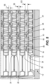
- the illustrated upstanding impressions 68, 70 are generally centered over the respective descending impressions 88, 90.
- the central portions of the upstanding impression 68, 70 abut the central portions of the descending impressions 88, 90.
- the upstanding impressions 68, 70 are somewhat offset from the respective descending impressions 88, 90.
- a non-central portion of the upstanding impressions 68, 70 abuts a central portion of the descending impression 88, 90.
- a central portion of the upstanding impressions 68, 70 abuts a non-central portion of the descending impression 88, 90.
- a non-central portion of the upstanding impressions 68, 70 abuts a non-central portion of the descending impression 88, 90.
- FIG. 8 illustrates the simulation results of several different types of heat exchanger configurations.
- a standard dimple configuration (DIMPLE) having a passage height of 0.9mm is used as the control.
- the remaining configurations are compared to the standard dimple configuration for both the pressure drop change across the coolant passage (X axis) and for the heat exchanger performance change (Y axis).
- the legend indicates the dimple height as D, and the passage height as P.
- the HD DIMPLE configuration is sold by a competitor and includes high density dimples.
- the P DIMPLE configurations are disclosed in DE 10 2018 007 010 A1 .
- the O DIMPLE configurations include the dimples from DE 10 2018 007 010 A1 on both sets of tube sheets.
- the chevron design is shown in FIGS. 9-11 and is discussed in more detail below.
- the ANGLE DIMPLE configurations are newly disclosed herein. Different geometric values, such as the third angle 110, the height of the impressions and the fluid passage height were varied to obtain five different simulation results. Each of these results outperformed the prior art configurations, as shown in FIG. 8 .
- the ANGLE DIMPLE configurations such as the configuration described above, demonstrated an improvement in heat exchanger performance while maintaining an acceptable pressure drop across the coolant passage. Some of the configurations had a decreased pressure drop along with an improved heat exchanger performance as shown in FIG. 8 . As noted in the background, it is desirable to maintain a relatively low pressure drop across the heat exchanger without compromising heat exchanger performance.
- the present configuration achieves the desired result of improved heat exchanger performance and decreased pressure drop across the coolant passage.
- the TURBULATOR configuration shows a configuration in which a turbulator is included between each of the heat exchanger plates, both in the coolant passageways and the oil passageways.
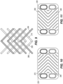
- FIGS. 9-11 illustrate an alternative embodiment that includes upstanding impressions 268, 270 that extend on opposite halves of the first heat exchanger plate 226 in a chevron shape.
- the data for this design is included in the FIG. 8 graph as CHEVRON.
- upstanding impressions 268 extend diagonally with respect to the first heat exchanger plate 226 and intersect upstanding impressions 270 at approximately a 90-degree angle in the middle of the first heat exchanger plate 226.
- descending impressions 288, 290 extend on opposite halves of the second heat exchanger plate 228 in a chevron shape.
- Descending impressions 288 extend diagonally with respect to the second heat exchanger plate 228 and intersect descending impressions 290 at approximately a 90-degree angle in the middle of the second heat exchanger plate 228. As shown schematically in FIG. 9 , each upstanding impression 268, 270 abuts portions of several descending impressions 288, 290. Likewise, each descending impression 288, 290 abuts portions of several upstanding impressions 268, 270. Each abutment is connected (e.g., joined, brazed etc.) and coolant is permitted to flow over the upstanding impressions 268, 270 and under the descending impressions 288, 290 around each abutment.
- FIGS. 9-11 orients the upstanding impressions 268 at an angle between 60 and 120 degrees with respect to the upstanding impressions 270.
- such embodiments can orient the descending impression 288 at an angle between 60 and 120 degrees with respect to the descending impression 290.
- the present application presents different embodiments of heat exchanger protrusion configurations that enhance heat exchanger performance while maintaining a low pressure drop relative to other protrusion configurations.
Landscapes
- Engineering & Computer Science (AREA)
- Physics & Mathematics (AREA)
- Thermal Sciences (AREA)
- Mechanical Engineering (AREA)
- General Engineering & Computer Science (AREA)
- Heat-Exchange Devices With Radiators And Conduit Assemblies (AREA)
Abstract
Description
- The present disclosure relates to heat exchangers. Heat exchangers include a plurality of alternating plates to allow heat exchange between two different fluids. In oil coolers, oil and coolant flow between adjacent plates. In order to enhance the heat exchange between the adjacent plates, the alternating plates often include one or more protrusions and/or turbulator inserts. However, the protrusions and turbulators increase the pressure drop across the heat exchangers, which is undesirable.
- It is an object of the present invention to provide a heat exchanger protrusion configuration that enhances heat exchange while maintaining a low pressure drop relative to other protrusion configurations.
- In some embodiments, an oil cooler is connected to a vehicle. The oil cooler includes a flange plate having fastener apertures and fluid flow apertures. The fastener apertures are each sized to receive a fastener to connect the flange plate to the vehicle. The fluid flow apertures permit oil and coolant to flow through the flange plate.
- In some embodiments, a base heat exchanger plate having a first surface connected to the flange plate and a second surface spaced away from the flange plate. The base heat exchanger plate includes fluid flow apertures that to permit oil and coolant to flow through the base heat exchanger plate.
- In some embodiments, a first heat exchanger plate coupled to the base heat exchanger plate. The first heat exchanger plate has a first perimeter portion and a first central portion. The first perimeter portion surrounds the first central portion and includes a first upwardly extending flange. The first central portion includes a first generally planar surface and a plurality of upstanding impressions extending upwardly from the generally planar surface away from the base heat exchanger plate. An upper distal portion of the upstanding impressions is spaced a first distance from the first generally planar surface. The upper distal portion extends along a first length.
- In some embodiments, a second heat exchanger plate is connected to the first heat exchanger plate. The second heat exchanger plate has a second perimeter portion and a second central portion. The second perimeter portion surrounds the second central portion and includes a second upwardly extending flange. The second upwardly extending flange can contact an inner surface of the first upwardly extending flange to thereby connect the second heat exchanger plate to the first heat exchanger plate. The second central portion includes a second generally planar surface and a plurality of descending impressions extending downwardly from the second generally planar surface toward the base heat exchanger plate. A lower distal portion of the descending impressions is spaced a second distance from the second generally planar surface. The second generally planar surface is spaced from the first generally planar surface a third distance while the second heat exchanger plate is connected to the first heat exchanger plate. The lower distal portion extends along a second length.
- In some embodiments, a turbulator positioned on an upper surface of the second heat exchanger plate.
- In some embodiments, the first distance is less than the third distance and the second distance is less than the third distance.
- In some embodiments, a third length of the upper distal portion of one of the upstanding impressions is configured to abut fourth length of the lower distal portion of the corresponding descending impression.
- In some embodiments, the third length is less than the first length and the fourth length is less than the second length.
- In some embodiments, a third heat exchanger plate is positioned above the turbulator, and a fourth heat exchanger plate is positioned above the third heat exchanger plate. The third heat exchanger plate being substantially identical to the first heat exchanger plate and the fourth heat exchanger plate being substantially identical to the second heat exchanger plate. The oil cooler directs coolant between the first heat exchanger plate and the second heat exchanger plate, and directs oil through the turbulator between the second heat exchanger plate and the third heat exchanger plate.
- In some embodiments, the upper distal portion extends along a first width measured perpendicular to the first length, and the lower distal portion extends along a second width measured perpendicular to the second length, the first length being greater than the first width and the second length being greater than the second width.
- In some embodiments, the first length is at least twice the first width and the second length is at least twice the second width.
- In some embodiments, the first upwardly extending flange is generally rectangular having opposite short sides and opposite long sides. The upstanding impressions extend diagonally with respect to the opposite short sides and with respect to the opposite long sides of the first upwardly extending flange.
- In some embodiments, the second upwardly extending flange is generally rectangular having opposite short sides and opposite long sides, and wherein the descending impressions extend diagonally with respect to the opposite short sides and with respect to the opposite long sides of the first upwardly extending flange.
- In some embodiments, each upstanding impression extends in a non-parallel direction with respect to the respective descending impression, such that each upstanding impression abuts the respective descending impression along a portion of the first length and a portion of the second length.
- In some embodiments, the upstanding impressions extend at an angle of between about 60 to 120 degrees with respect to the descending impressions, such that coolant is permitted to flow over the upstanding impressions and under the descending impressions around the portion of the first length and the portion of the second length that are connected.
- In some embodiments, the first distance plus the second distance is substantially equal to the third distance.
- In some embodiments, the first distance is substantially equal to the second distance.
- In some embodiments, upstanding impressions are elongate and include a tapered perimeter and a flattened upper surface, and wherein the second descending impressions are elongate and include a tapered perimeter and a flattened lower surface.
- In some embodiments, a first portion of each of the upstanding impressions is in abutment with a first portion of the respective descending impressions, a second portion of the upstanding impressions is spaced from the respective descending impressions, and a second portion of the descending impressions is spaced from the respective upstanding impressions, such that coolant is permitted to flow over the second portions of the upstanding impressions, and coolant is permitted to flow under the second portions of the descending impressions.
- In some embodiments, the first portion of each of the upstanding impressions is generally centrally located along the first length of the respective upstanding impression, and wherein the first portion of each of the descending impressions is generally centrally located along the second length of the respective descending impression.
- In some embodiments, the present application is directed to a vehicle including the oil cooler shown and described herein.
- Other aspects of the disclosure will become apparent by consideration of the detailed description and accompanying drawings.
-
-
FIG. 1 is a perspective view of an oil cooler according to some embodiments of the present invention. -
FIG. 2 is a partially exploded view of the oil cooler ofFIG. 1 . -
FIG. 3 is a top view of a first heat exchanger plate. -
FIG. 3A is a close-up view of a portion of the first heat exchanger plate ofFIG. 3 . -
FIG. 4 is a top view of a second heat exchanger plate. -
FIG. 4A is a close up view of a portion of the second heat exchanger plate ofFIG. 4 . -
FIG. 5 is a cross-sectional view taken along line 5-5 ofFIG. 1 . -
FIG. 6 is a close-up cross-sectional view of two adjacent heat exchanger plates. -
FIG. 7 is a schematic view showing the flow path between the heat exchanger plates ofFIG. 6 . -
FIG. 8 is a graph comparing the pressure drop and heat exchanger performance of the present configuration in comparison to a standard dimple configuration. -
FIG. 9 shows a schematic view of one possible alternate embodiment. -
FIG. 10 is a top view of the first plate according to the embodiment ofFIG. 9 . -
FIG. 11 is a top view of the second plate according to the embodiment ofFIG. 9 . - Before any embodiments of the disclosure are explained in detail, it is to be understood that the disclosure is not limited in its application to the details of construction and the arrangement of components set forth in the following description or illustrated in the following drawings. The disclosure is capable of other embodiments and of being practiced or of being carried out in various ways.
-
FIG. 1 illustrates an oil cooler 10 including aflange plate 12 and a stack ofheat exchanger plates 14. Theflange plate 12 includes a plurality offastener apertures 16,coolant flow apertures 18 andoil flow apertures 20. The fastener apertures 16 are each configured to receive a fastener to couple theflange plate 12 to a vehicle. Thecoolant flow apertures 18 are configured to permit coolant to flow through theflange plate 12 and theoil flow apertures 20 that are configured to permit oil to flow through theflange plate 12. -
FIG. 2 illustrates the stack ofheat exchanger plates 14 in greater detail. The illustrated stack ofheat exchanger plates 14 includes a baseheat exchanger plate 24, a plurality of firstheat exchanger plates 26, a plurality of secondheat exchanger plates 28, a plurality ofturbulators 30, an endheat exchanger plate 32 and anend plate 34. - The base
heat exchanger plate 24 is generally planar and includes an upwardly extendingflange 40 around a perimeter of the baseheat exchanger plate 24. The generally planar portion of the baseheat exchanger plate 24 includes a first surface configured to be coupled to theflange plate 12 and asecond surface 44 spaced away from theflange plate 12. The baseheat exchanger plate 24 includes coolant flow apertures that are substantially aligned with thecoolant flow apertures 18 while the baseheat exchanger plate 24 is coupled to theflange plate 12. Similarly, the baseheat exchanger plate 24 includes oil flow apertures that are substantially aligned with theoil flow apertures 20 while the baseheat exchanger plate 24 is coupled to theflange plate 12. - One of the plurality of first
heat exchanger plates 26 is positioned above and coupled to the baseheat exchanger plate 24. In some embodiments, a turbulator is positioned between the baseheat exchanger plate 24 and the firstheat exchanger plate 26. One of the plurality of secondheat exchanger plates 28 is positioned above coupled to the firstheat exchanger plate 26 opposite the baseheat exchanger plate 24. One of the plurality ofturbulators 30 is positioned above the secondheat exchanger plate 28 opposite the firstheat exchanger plate 26. The firstheat exchanger plates 26 alternate with the secondheat exchanger plates 28, and aturbulator 30 is positioned above each secondheat exchanger plate 28. The first and secondheat exchanger plates - The illustrated end
heat exchanger plate 32 is positioned on the top of the upper secondheat exchanger plate 28 and theupper turbulator 30. The endheat exchanger plate 32 includes a generally planar portion and includes an upwardly extendingflange 50 around a perimeter of the endheat exchanger plate 32. The generally planar portion of the endheat exchanger plate 32 includes a first surface configured to contact theupper turbulator 30 and asecond surface 54 spaced away from theupper turbulator 30. The illustrated endheat exchanger plate 32 includesdepressions 56 positioned above thecoolant flow apertures 18. - The
illustrated end plate 34 is generally planar and is configured to be coupled to second surface of the endheat exchanger plate 32. Theend plate 34 is configured to increase the rigidity of theoil cooler 10. In some embodiments, theend plate 34 is omitted. - The illustrated
flange plate 12, baseheat exchanger plate 24, endheat exchanger plate 32 andend plate 34 are provided as one possible configuration. Other configurations of flange plates, base heat exchanger plates, end heat exchanger plates and end plates are possible and are considered to be within the scope of the present disclosure. -
FIG. 3 illustrates one firstheat exchanger plate 26 in greater detail. Each firstheat exchanger plate 26 is substantially identical, so only one firstheat exchanger plate 26 will be described in detail herein. The firstheat exchanger plate 26 has afirst perimeter portion 60 and a firstcentral portion 62. Thefirst perimeter portion 60 surrounds the firstcentral portion 62 and includes a first upwardly extending flange 64 (seeFIG. 2 ). - The first
central portion 62 includes a first generallyplanar surface 66 and a plurality ofupstanding impressions heat exchanger plate 24. The first upwardly extendingflange 64 is generally rectangular and has opposite short sides and opposite long sides. All of theupstanding impressions flange 64. -
FIG. 3A illustrates theupstanding impressions upstanding impressions upstanding impressions 68 are oriented at a non-parallel angle with respect to theupstanding impressions 70. In the illustrated embodiment, the angle between theupstanding impressions - The
upstanding impressions first length 72 measured parallel to the first generallyplanar surface 66, and afirst width 74 measured perpendicular to thefirst length 72. Thefirst length 72 is longer than thefirst width 74. In the illustrated embodiment, thefirst length 72 is more than twice thefirst width 74. - Optionally,
upstanding impressions 68a are included near the long sides of the first upwardly extendingflange 64. These optionalupstanding impressions 68a have a shorter length than the remainingupstanding impressions upstanding impressions 68a are spaced inward from the first upwardly extendingflange 64 and can be adjusted in size to accommodate different size requirements of theoverall oil cooler 10. The illustrated optionalupstanding impressions 68a are parallel to theupstanding impressions 68. In some embodiments, some of the optional upstanding impressions are oriented parallel to theupstanding impressions 70. -
FIG. 4 illustrates the secondheat exchanger plate 28 in greater detail. Each secondheat exchanger plate 28 is substantially identical, so only one secondheat exchanger plate 28 will be described in detail herein. The secondheat exchanger plate 28 has asecond perimeter portion 80 and a secondcentral portion 82. Thesecond perimeter portion 80 surrounds the secondcentral portion 82 and includes a second upwardly extending flange 84 (seeFIG. 2 ). An outer surface of the second upwardly extendingflange 84 is configured to contact an inner surface of the first upwardly extendingflange 64 to thereby couple the secondheat exchanger plate 28 to the firstheat exchanger plate 26. - The second
central portion 82 includes a second generallyplanar surface 86 and a plurality of descendingimpressions planar surface 86 toward the baseheat exchanger plate 24. - The second upwardly extending
flange 84 is generally rectangular and has opposite short sides and opposite long sides. All of the descendingimpressions flange 84. -
FIG. 4A illustrates the descendingimpressions descending impressions impressions 88 are oriented at a non-parallel angle with respect to the descendingimpressions 90. In the illustrated embodiment, the angle between the descendingimpressions - The descending
impressions second length 92 measured parallel to the second generallyplanar surface 86, and asecond width 94 measured perpendicular to thesecond length 92. While the upper face of the secondheat exchanger plate 28 is illustrated, it is to be understood that thesecond length 92 andsecond width 94 are measured on the lower surface of the second heat exchanger plate. Thesecond length 92 is longer than thesecond width 94. In the illustrated embodiment, thesecond length 92 is more than twice thesecond width 94. - Optionally, descending
impressions 88a are included near the long sides of the second upwardly extendingflange 84. Theseoptional descending impressions 88a have a shorter length than the remainingdescending impressions optional descending impressions 88a are spaced inwardly from the second upwardly extendingflange 84 and can be adjusted in size to accommodate different size requirements of theoverall oil cooler 10. The illustrated optionalupstanding impressions 88a are parallel to theupstanding impressions 88. In some embodiments, some of the optional upstanding impressions are oriented parallel to theupstanding impressions 90. - As shown in
FIGS. 5 and6 , the perimeter of theupstanding impressions planar surface 66 and the upper distal portion. The perimeter of the descendingimpressions planar surface 86 and the lower distal portion. - The upper distal portion of the
upstanding impressions impressions upstanding impression first distance 96 above the first generallyplanar surface 66. The lower distal portion of each descendingimpression second distance 98 from the second generallyplanar surface 86. - While the first
heat exchanger plate 26 is joined to the secondheat exchanger plate 28, the first generallyplanar surface 66 of the firstheat exchanger plate 26 is spaced athird distance 100 from the second generallyplanar surface 86 of the secondheat exchanger plate 28. Thefirst distance 96 is less than thethird distance 100 and thesecond distance 98 is less than thethird distance 100. - The
first distance 96 plus thesecond distance 98 is substantially equal to thethird distance 100 to permit the abutting portions of the first and secondheat exchanger plates first distance 96 is approximately equal to thesecond distance 98. In other embodiments, thefirst distance 96 is different than thesecond distance 98. - Each of the
upstanding impressions 68 is positioned to abut a respective one of the descendingimpressions 88, and each of theupstanding impressions 70 is positioned to abut a respective one of the descendingimpressions 90 when the firstheat exchanger plate 26 is joined to the secondheat exchanger plate 28. The coolant is configured to flow over theupstanding impressions impressions turbulator 30. The contact betweenadjacent impressions second plates oil cooler 10. - As shown in
FIG. 6 , theupstanding impressions respective descending impressions upstanding impressions respective descending impressions upstanding impressions impressions upstanding impression respective descending impression - With reference to
FIG. 7 , the upper surface of the upper distal portions of theupstanding impressions impressions upstanding impressions first length 72 and thefirst width 74. The lower surface of the lower distal portion of each of the illustrated descendingimpressions second length 92 and thesecond width 94. Only a portion of the upper surface of the upper distal portion of eachupstanding impression respective descending impression upstanding impressions impressions upstanding impression respective descending impression respective descending impression impression upstanding impression upstanding impression -
FIG. 7 shows an angle of about 90 degrees between theupstanding impressions impressions upstanding impressions impressions upstanding impressions impressions width upstanding impressions respective descending impressions overall length 72 of the upper distal portion of the respectiveupstanding impressions overall length 92 of the lower distal portion of the descendingimpressions - The fluid flow direction is shown by
arrow 104. Afirst angle 106 is measured between theupstanding impression 70 and the descendingimpression 90. Asecond angle 108 is the supplementary angle of thefirst angle 106. Athird angle 110 is measured between the descendingimpression 90 and thefluid flow direction 104. Thethird angle 110 is half of thefirst angle 106. Thethird angle 110 is between about 30 and 60 degrees. - The remaining portion of the upper distal portion of the
upstanding impressions respective descending impression upstanding impressions FIG. 7 . The remaining portion of the lower distal portion of the descendingimpressions upstanding impression impressions - The illustrated
upstanding impressions respective descending impressions upstanding impression impressions upstanding impressions respective descending impressions upstanding impressions impression upstanding impressions impression upstanding impressions impression -
FIG. 8 illustrates the simulation results of several different types of heat exchanger configurations. A standard dimple configuration (DIMPLE) having a passage height of 0.9mm is used as the control. The remaining configurations are compared to the standard dimple configuration for both the pressure drop change across the coolant passage (X axis) and for the heat exchanger performance change (Y axis). The legend indicates the dimple height as D, and the passage height as P. - The HD DIMPLE configuration is sold by a competitor and includes high density dimples. The P DIMPLE configurations are disclosed in
DE 10 2018 007 010 A1DE 10 2018 007 010 A1FIGS. 9-11 and is discussed in more detail below. - The ANGLE DIMPLE configurations are newly disclosed herein. Different geometric values, such as the
third angle 110, the height of the impressions and the fluid passage height were varied to obtain five different simulation results. Each of these results outperformed the prior art configurations, as shown inFIG. 8 . The ANGLE DIMPLE configurations, such as the configuration described above, demonstrated an improvement in heat exchanger performance while maintaining an acceptable pressure drop across the coolant passage. Some of the configurations had a decreased pressure drop along with an improved heat exchanger performance as shown inFIG. 8 . As noted in the background, it is desirable to maintain a relatively low pressure drop across the heat exchanger without compromising heat exchanger performance. The present configuration achieves the desired result of improved heat exchanger performance and decreased pressure drop across the coolant passage. - The TURBULATOR configuration shows a configuration in which a turbulator is included between each of the heat exchanger plates, both in the coolant passageways and the oil passageways.
-
FIGS. 9-11 illustrate an alternative embodiment that includesupstanding impressions heat exchanger plate 226 in a chevron shape. The data for this design is included in theFIG. 8 graph as CHEVRON. Essentially,upstanding impressions 268 extend diagonally with respect to the firstheat exchanger plate 226 and intersectupstanding impressions 270 at approximately a 90-degree angle in the middle of the firstheat exchanger plate 226. Similarly descendingimpressions heat exchanger plate 228 in a chevron shape. Descendingimpressions 288 extend diagonally with respect to the secondheat exchanger plate 228 and intersect descendingimpressions 290 at approximately a 90-degree angle in the middle of the secondheat exchanger plate 228. As shown schematically inFIG. 9 , eachupstanding impression impressions impression upstanding impressions upstanding impressions impressions - In other embodiments, the configuration of
FIGS. 9-11 orients theupstanding impressions 268 at an angle between 60 and 120 degrees with respect to theupstanding impressions 270. Similarly, such embodiments can orient the descendingimpression 288 at an angle between 60 and 120 degrees with respect to the descendingimpression 290. - The present application presents different embodiments of heat exchanger protrusion configurations that enhance heat exchanger performance while maintaining a low pressure drop relative to other protrusion configurations.
Claims (14)
- An oil cooler (10) configured to be coupled to a vehicle, the oil cooler (10) comprising:a flange plate (12) including fastener apertures (16) and fluid flow apertures, the fastener apertures (16) each configured to receive a fastener to couple the flange plate (12) to the vehicle, the fluid flow apertures (18, 20) configured to permit oil and coolant to flow through the flange plate (12);a base heat exchanger plate (24) having a first surface coupled to the flange plate (12) and a second surface (44) spaced away from the flange plate (12), the base heat exchanger plate (24) including fluid flow apertures extending therethrough to permit oil and coolant to flow through the base heat exchanger plate (24);a first heat exchanger plate (26) coupled to the base heat exchanger plate (24), the first heat exchanger plate (26) having a first perimeter portion (60) and a first central portion (62), the first perimeter portion (60) surrounding the first central portion (62) and including a first upwardly extending flange (40), the first central portion (62) including a first generally planar surface (66) and a plurality of upstanding impressions (68, 70) extending upwardly from the generally planar surface (66) away from the base heat exchanger plate (24), an upper distal portion of the upstanding impressions (68, 70) spaced a first distance (96) from the first generally planar surface (66), the upper distal portion extending along a first length (72);a second heat exchanger plate (28) coupled to the first heat exchanger plate (26), the second heat exchanger plate (28) having a second perimeter portion (80) and a second central portion (82), the second perimeter portion (80) surrounding the second central portion (82) and including a second upwardly extending flange (40), the second upwardly extending flange (40) configured to contact an inner surface of the first upwardly extending flange (40) to thereby couple the second heat exchanger plate (28) to the first heat exchanger plate (26), the second central portion (82) including a second generally planar surface (66) and a plurality of descending impressions (88, 90) extending downwardly from the second generally planar surface (66) toward the base heat exchanger plate (24), a lower distal portion of the descending impressions (88, 90) spaced a second distance (98) from the second generally planar surface (66), the second generally planar surface (66) spaced from the first generally planar surface (66) a third distance (100) while the second heat exchanger plate (28) is coupled to the first heat exchanger plate (26), the lower distal portion extending along a second length (92); anda turbulator (30) positioned on an upper surface of the second heat exchanger plate (28),wherein the first distance (96) is less than the third distance (100) and the second distance (98) is less than the third distance (100),wherein a third length of the upper distal portion of one of the upstanding impressions (68, 70) is configured to abut a fourth length of the lower distal portion of the corresponding descending impression (88, 90), andwherein the third length is less than the first length (72) and the fourth length is less than the second length (92).
- The oil cooler (10) of claim 1, further comprising a third heat exchanger plate positioned above the turbulator (30), and a fourth heat exchanger plate positioned above the third heat exchanger plate, the third heat exchanger plate being substantially identical to the first heat exchanger plate (26) and the fourth heat exchanger plate being substantially identical to the second heat exchanger plate (28), wherein the oil cooler (10) is configured to direct coolant between the first heat exchanger plate (26) and the second heat exchanger plate (28), and is configured to direct oil through the turbulator (30) between the second heat exchanger plate (28) and the third heat exchanger plate.
- The oil cooler (10) of claim 1 or claim 2, wherein the upper distal portion extends along a first width (74) measured perpendicular to the first length (72), and the lower distal portion extends along a second width (94) measured perpendicular to the second length (92), the first length (72) being greater than the first width (74) and the second length (92) being greater than the second width (94).
- The oil cooler (10) of claim 3, wherein the first length (72) is at least twice the first width (74) and wherein the second length (92) is at least twice the second width (94).
- The oil cooler (10) of any of claims 1 to 4, wherein the first upwardly extending flange (40) is generally rectangular having opposite short sides and opposite long sides, and wherein the upstanding impressions (68, 70) extend diagonally with respect to the opposite short sides and with respect to the opposite long sides of the first upwardly extending flange (40).
- The oil cooler (10) of any of claims 1 to 5, wherein the second upwardly extending flange (40) is generally rectangular having opposite short sides and opposite long sides, and wherein the descending impressions (88, 90) extend diagonally with respect to the opposite short sides and with respect to the opposite long sides of the first upwardly extending flange (40).
- The oil cooler (10) of any of claims 1 to 6, wherein each upstanding impression (68, 70) extends in a non-parallel direction with respect to the respective descending impression (88, 90), such that each upstanding impression (68, 70) abuts the respective descending impression (88, 90) along a portion of the first length (72) and a portion of the second length (92).
- The oil cooler (10) of any of claims 1 to 7, wherein the upstanding impressions (68, 70) extend at an angle of between about 60 to 120 degrees with respect to the descending impressions (88, 90), such that coolant is permitted to flow over the upstanding impressions (68, 70) and under the descending impressions (88, 90) around the portion of the first length (72) and the portion of the second length (92) that are connected.
- The oil cooler (10) of any of claims 1 to 8, wherein the first distance (96) plus the second distance (98) is substantially equal to the third distance (100).
- The oil cooler (10) of any of claims 1 to 9, wherein the first distance (96) is substantially equal to the second distance (98).
- The oil cooler (10) of any of claims 1 to 10, wherein the upstanding impressions (68, 70) are elongate and include a tapered perimeter and a flattened upper surface, and wherein the second descending impressions (88, 90) are elongate and include a tapered perimeter and a flattened lower surface.
- The oil cooler (10) of any of claims 1 to 11, wherein a first portion of each of the upstanding impressions (68, 70) is in abutment with a first portion of the respective descending impressions (88, 90), a second portion of the upstanding impressions (68, 70) is spaced from the respective descending impressions (88, 90), and a second portion of the descending impressions (88, 90) is spaced from the respective upstanding impressions (68, 70), such that coolant is permitted to flow over the second portions of the upstanding impressions (68, 70), and coolant is permitted to flow under the second portions of the descending impressions (88, 90).
- The oil cooler (10) of claim 12, wherein the first portion of each of the upstanding impressions (68, 70) is generally centrally located along the first length (72) of the respective upstanding impression (68, 70), and wherein the first portion of each of the descending impressions (88, 90) is generally centrally located along the second length (92) of the respective descending impression (88, 90).
- A vehicle including the oil cooler (10) of any of claims 1 to 13.
Priority Applications (3)
| Application Number | Priority Date | Filing Date | Title |
|---|---|---|---|
| EP23191133.0A EP4506649B1 (en) | 2023-08-11 | 2023-08-11 | Heat exchanger dimple configuration |
| US18/799,086 US12590765B2 (en) | 2023-08-11 | 2024-08-09 | Heat exchanger dimple configuration |
| CN202411093639.9A CN119468760A (en) | 2023-08-11 | 2024-08-09 | Heat exchanger pit structure |
Applications Claiming Priority (1)
| Application Number | Priority Date | Filing Date | Title |
|---|---|---|---|
| EP23191133.0A EP4506649B1 (en) | 2023-08-11 | 2023-08-11 | Heat exchanger dimple configuration |
Publications (2)
| Publication Number | Publication Date |
|---|---|
| EP4506649A1 true EP4506649A1 (en) | 2025-02-12 |
| EP4506649B1 EP4506649B1 (en) | 2025-10-01 |
Family
ID=87571035
Family Applications (1)
| Application Number | Title | Priority Date | Filing Date |
|---|---|---|---|
| EP23191133.0A Active EP4506649B1 (en) | 2023-08-11 | 2023-08-11 | Heat exchanger dimple configuration |
Country Status (3)
| Country | Link |
|---|---|
| US (1) | US12590765B2 (en) |
| EP (1) | EP4506649B1 (en) |
| CN (1) | CN119468760A (en) |
Families Citing this family (1)
| Publication number | Priority date | Publication date | Assignee | Title |
|---|---|---|---|---|
| CN121631842A (en) * | 2024-09-10 | 2026-03-10 | 绍兴三花汽车热管理科技有限公司 | Heat exchanger |
Citations (5)
| Publication number | Priority date | Publication date | Assignee | Title |
|---|---|---|---|---|
| DE19519312A1 (en) * | 1995-05-26 | 1996-11-28 | Laengerer & Reich Gmbh & Co | Plate-type heat-exchanger |
| EP0867679A2 (en) * | 1997-03-25 | 1998-09-30 | KTM-Kühler GmbH | Plate-like heat exchanger, more particularly oil cooler |
| US6209629B1 (en) * | 1999-07-09 | 2001-04-03 | Visteon Global Technologies, Inc. | Beaded plate for a heat exchanger and method of making same |
| CA2298118C (en) * | 1999-02-05 | 2007-03-13 | Long Manufacturing Ltd. | Self enclosing heat exchangers |
| US20200072556A1 (en) * | 2016-12-26 | 2020-03-05 | T.Rad Co., Ltd. | Structure joined by nickel brazing |
Family Cites Families (24)
| Publication number | Priority date | Publication date | Assignee | Title |
|---|---|---|---|---|
| JPS625096A (en) * | 1985-06-28 | 1987-01-12 | Nippon Denso Co Ltd | Lamination type heat exchanger |
| US4815532A (en) | 1986-02-28 | 1989-03-28 | Showa Aluminum Kabushiki Kaisha | Stack type heat exchanger |
| DE3622316C1 (en) * | 1986-07-03 | 1988-01-28 | Schmidt W Gmbh Co Kg | Plate heat exchanger |
| JP4122578B2 (en) * | 1997-07-17 | 2008-07-23 | 株式会社デンソー | Heat exchanger |
| DE19909881A1 (en) * | 1999-03-06 | 2000-09-07 | Behr Gmbh & Co | Cross-flow heat exchanger of plate stack between cover plates uses knob or pleat forms of stack plates to define flow path between inlet and outlet using oval knobs and specified flow path dimensions. |
| DE10347181B4 (en) * | 2003-10-10 | 2005-12-22 | Modine Manufacturing Co., Racine | Heat exchangers, in particular oil coolers |
| DE102004003790A1 (en) * | 2004-01-23 | 2005-08-11 | Behr Gmbh & Co. Kg | Heat exchangers, in particular oil / coolant coolers |
| SE528879C2 (en) * | 2005-07-04 | 2007-03-06 | Alfa Laval Corp Ab | Heat exchanger plate, pair of two heat exchanger plates and plate package for plate heat exchanger |
| DE102006022445A1 (en) * | 2006-05-13 | 2007-11-15 | Modine Manufacturing Co., Racine | Heat exchangers, in particular oil coolers |
| SE530011C2 (en) * | 2006-06-05 | 2008-02-05 | Alfa Laval Corp Ab | Heat exchanger plate and plate heat exchanger |
| US20080078538A1 (en) * | 2006-09-28 | 2008-04-03 | Ali Jalilevand | Heat exchanger plate having integrated turbulation feature |
| US20110277974A1 (en) * | 2009-09-30 | 2011-11-17 | Carrier Corporation | Condensing Heat Exchanger for Gas Furnaces |
| ES2706986T3 (en) * | 2012-03-28 | 2019-04-02 | Alfa Laval Corp Ab | New brazing concept |
| US20140158328A1 (en) * | 2012-07-05 | 2014-06-12 | Airec Ab | Plate for heat exchanger, heat exchanger and air cooler comprising a heat exchanger |
| US20140008046A1 (en) * | 2012-07-05 | 2014-01-09 | Airec Ab | Plate for heat exchanger, heat exchanger and air cooler comprising a heat exchanger |
| SE537148C2 (en) * | 2012-10-22 | 2015-02-17 | Alfa Laval Corp Ab | Plate heat exchanger plate and plate heat exchanger |
| DK177839B1 (en) | 2013-03-08 | 2014-09-08 | Danfoss As | Heat exchanger with dimples connected by wall sections |
| JP6671170B2 (en) | 2015-12-28 | 2020-03-25 | 株式会社マーレ フィルターシステムズ | Heat exchanger |
| CN107782179A (en) | 2016-08-25 | 2018-03-09 | 杭州三花研究院有限公司 | Plate type heat exchanger |
| SE542057C2 (en) * | 2016-08-25 | 2020-02-18 | Alfa Laval Corp Ab | A heat exchanger plate, and a plate heat exchanger |
| DE102018007010A1 (en) | 2018-09-05 | 2020-03-05 | Modine Manufacturing Co. | Fluid flow channel with efficiency-increasing transformations |
| SE543419C2 (en) * | 2019-02-26 | 2021-01-12 | Alfa Laval Corp Ab | A heat exchanger plate and a plate heat exchanger |
| US11280559B2 (en) * | 2020-05-12 | 2022-03-22 | Hanon Systems | Dumbbell shaped plate fin |
| US12474129B2 (en) * | 2020-08-31 | 2025-11-18 | Kyungdong Navien Co., Ltd. | Heat exchanger assembly and water heater comprising same |
-
2023
- 2023-08-11 EP EP23191133.0A patent/EP4506649B1/en active Active
-
2024
- 2024-08-09 CN CN202411093639.9A patent/CN119468760A/en active Pending
- 2024-08-09 US US18/799,086 patent/US12590765B2/en active Active
Patent Citations (5)
| Publication number | Priority date | Publication date | Assignee | Title |
|---|---|---|---|---|
| DE19519312A1 (en) * | 1995-05-26 | 1996-11-28 | Laengerer & Reich Gmbh & Co | Plate-type heat-exchanger |
| EP0867679A2 (en) * | 1997-03-25 | 1998-09-30 | KTM-Kühler GmbH | Plate-like heat exchanger, more particularly oil cooler |
| CA2298118C (en) * | 1999-02-05 | 2007-03-13 | Long Manufacturing Ltd. | Self enclosing heat exchangers |
| US6209629B1 (en) * | 1999-07-09 | 2001-04-03 | Visteon Global Technologies, Inc. | Beaded plate for a heat exchanger and method of making same |
| US20200072556A1 (en) * | 2016-12-26 | 2020-03-05 | T.Rad Co., Ltd. | Structure joined by nickel brazing |
Also Published As
| Publication number | Publication date |
|---|---|
| US20250052510A1 (en) | 2025-02-13 |
| US12590765B2 (en) | 2026-03-31 |
| EP4506649B1 (en) | 2025-10-01 |
| CN119468760A (en) | 2025-02-18 |
Similar Documents
| Publication | Publication Date | Title |
|---|---|---|
| JP2920696B2 (en) | Plate heat exchanger with improved corrugated passage | |
| US11454448B2 (en) | Enhanced heat transfer surface | |
| US10473403B2 (en) | Heat exchanger | |
| EP2394129B1 (en) | A plate heat exchanger | |
| US20090188655A1 (en) | Heat exchanger flat tube with oblique elongate dimples | |
| US6675878B2 (en) | Angled turbulator for use in heat exchangers | |
| CN102016480A (en) | A plate heat exchanger | |
| JP4584976B2 (en) | Heat exchange plate and plate package | |
| CN105793662A (en) | Heat exchanger with improved flow | |
| US20070006998A1 (en) | Heat exchanger with plate projections | |
| US12590765B2 (en) | Heat exchanger dimple configuration | |
| US9453690B2 (en) | Stacked-plate heat exchanger with single plate design | |
| CN110537069A (en) | Heat transfer plate and heat exchanger including a plurality of such heat transfer plates | |
| JP2016539305A (en) | Heat exchange plate with various pitches | |
| JP2023513908A (en) | Heat transfer plates and plate heat exchangers | |
| JP5468827B2 (en) | Oil cooler | |
| JPH06174393A (en) | Heat exchanger | |
| JP2017514096A (en) | Heat exchanger with tube core | |
| CN101983311B (en) | A plate heat exchanger | |
| EP0838650B1 (en) | Humped plate fin heat exchangers | |
| US20240133634A1 (en) | A brazed plate heat exchanger | |
| KR20210026216A (en) | Plate type heat exchanger | |
| JP2021168367A (en) | Heat exchanger | |
| BR102024016325A2 (en) | OIL COOLER CONFIGURED TO BE ATTACHED TO A VEHICLE AND VEHICLE INCLUDING THE OIL COOLER | |
| JPH029275Y2 (en) |
Legal Events
| Date | Code | Title | Description |
|---|---|---|---|
| PUAI | Public reference made under article 153(3) epc to a published international application that has entered the european phase |
Free format text: ORIGINAL CODE: 0009012 |
|
| STAA | Information on the status of an ep patent application or granted ep patent |
Free format text: STATUS: REQUEST FOR EXAMINATION WAS MADE |
|
| 17P | Request for examination filed |
Effective date: 20240529 |
|
| AK | Designated contracting states |
Kind code of ref document: A1 Designated state(s): AL AT BE BG CH CY CZ DE DK EE ES FI FR GB GR HR HU IE IS IT LI LT LU LV MC ME MK MT NL NO PL PT RO RS SE SI SK SM TR |
|
| GRAP | Despatch of communication of intention to grant a patent |
Free format text: ORIGINAL CODE: EPIDOSNIGR1 |
|
| STAA | Information on the status of an ep patent application or granted ep patent |
Free format text: STATUS: GRANT OF PATENT IS INTENDED |
|
| INTG | Intention to grant announced |
Effective date: 20250428 |
|
| GRAS | Grant fee paid |
Free format text: ORIGINAL CODE: EPIDOSNIGR3 |
|
| GRAA | (expected) grant |
Free format text: ORIGINAL CODE: 0009210 |
|
| STAA | Information on the status of an ep patent application or granted ep patent |
Free format text: STATUS: THE PATENT HAS BEEN GRANTED |
|
| AK | Designated contracting states |
Kind code of ref document: B1 Designated state(s): AL AT BE BG CH CY CZ DE DK EE ES FI FR GB GR HR HU IE IS IT LI LT LU LV MC ME MK MT NL NO PL PT RO RS SE SI SK SM TR |
|
| REG | Reference to a national code |
Ref country code: GB Ref legal event code: FG4D Ref country code: CH Ref legal event code: F10 Free format text: ST27 STATUS EVENT CODE: U-0-0-F10-F00 (AS PROVIDED BY THE NATIONAL OFFICE) Effective date: 20251001 |
|
| REG | Reference to a national code |
Ref country code: IE Ref legal event code: FG4D |
|
| REG | Reference to a national code |
Ref country code: DE Ref legal event code: R096 Ref document number: 602023007095 Country of ref document: DE |
|
| REG | Reference to a national code |
Ref country code: NL Ref legal event code: MP Effective date: 20251001 |
|
| REG | Reference to a national code |
Ref country code: AT Ref legal event code: MK05 Ref document number: 1842847 Country of ref document: AT Kind code of ref document: T Effective date: 20251001 |
|
| PG25 | Lapsed in a contracting state [announced via postgrant information from national office to epo] |
Ref country code: NL Free format text: LAPSE BECAUSE OF FAILURE TO SUBMIT A TRANSLATION OF THE DESCRIPTION OR TO PAY THE FEE WITHIN THE PRESCRIBED TIME-LIMIT Effective date: 20251001 |
|
| PG25 | Lapsed in a contracting state [announced via postgrant information from national office to epo] |
Ref country code: ES Free format text: LAPSE BECAUSE OF FAILURE TO SUBMIT A TRANSLATION OF THE DESCRIPTION OR TO PAY THE FEE WITHIN THE PRESCRIBED TIME-LIMIT Effective date: 20251001 |
|
| REG | Reference to a national code |
Ref country code: LT Ref legal event code: MG9D |
|
| PG25 | Lapsed in a contracting state [announced via postgrant information from national office to epo] |
Ref country code: NO Free format text: LAPSE BECAUSE OF FAILURE TO SUBMIT A TRANSLATION OF THE DESCRIPTION OR TO PAY THE FEE WITHIN THE PRESCRIBED TIME-LIMIT Effective date: 20260101 |
|
| PG25 | Lapsed in a contracting state [announced via postgrant information from national office to epo] |
Ref country code: FI Free format text: LAPSE BECAUSE OF FAILURE TO SUBMIT A TRANSLATION OF THE DESCRIPTION OR TO PAY THE FEE WITHIN THE PRESCRIBED TIME-LIMIT Effective date: 20251001 Ref country code: HR Free format text: LAPSE BECAUSE OF FAILURE TO SUBMIT A TRANSLATION OF THE DESCRIPTION OR TO PAY THE FEE WITHIN THE PRESCRIBED TIME-LIMIT Effective date: 20251001 Ref country code: AT Free format text: LAPSE BECAUSE OF FAILURE TO SUBMIT A TRANSLATION OF THE DESCRIPTION OR TO PAY THE FEE WITHIN THE PRESCRIBED TIME-LIMIT Effective date: 20251001 |
|
| PG25 | Lapsed in a contracting state [announced via postgrant information from national office to epo] |
Ref country code: RS Free format text: LAPSE BECAUSE OF FAILURE TO SUBMIT A TRANSLATION OF THE DESCRIPTION OR TO PAY THE FEE WITHIN THE PRESCRIBED TIME-LIMIT Effective date: 20260101 |
|
| PG25 | Lapsed in a contracting state [announced via postgrant information from national office to epo] |
Ref country code: IS Free format text: LAPSE BECAUSE OF FAILURE TO SUBMIT A TRANSLATION OF THE DESCRIPTION OR TO PAY THE FEE WITHIN THE PRESCRIBED TIME-LIMIT Effective date: 20260201 |
|
| PG25 | Lapsed in a contracting state [announced via postgrant information from national office to epo] |
Ref country code: PT Free format text: LAPSE BECAUSE OF FAILURE TO SUBMIT A TRANSLATION OF THE DESCRIPTION OR TO PAY THE FEE WITHIN THE PRESCRIBED TIME-LIMIT Effective date: 20260202 Ref country code: CZ Free format text: LAPSE BECAUSE OF FAILURE TO SUBMIT A TRANSLATION OF THE DESCRIPTION OR TO PAY THE FEE WITHIN THE PRESCRIBED TIME-LIMIT Effective date: 20251001 |
|
| PG25 | Lapsed in a contracting state [announced via postgrant information from national office to epo] |
Ref country code: PL Free format text: LAPSE BECAUSE OF FAILURE TO SUBMIT A TRANSLATION OF THE DESCRIPTION OR TO PAY THE FEE WITHIN THE PRESCRIBED TIME-LIMIT Effective date: 20251001 |
|
| PG25 | Lapsed in a contracting state [announced via postgrant information from national office to epo] |
Ref country code: LV Free format text: LAPSE BECAUSE OF FAILURE TO SUBMIT A TRANSLATION OF THE DESCRIPTION OR TO PAY THE FEE WITHIN THE PRESCRIBED TIME-LIMIT Effective date: 20251001 |