EP4506626A1 - Degassing device - Google Patents
Degassing device Download PDFInfo
- Publication number
- EP4506626A1 EP4506626A1 EP24190620.5A EP24190620A EP4506626A1 EP 4506626 A1 EP4506626 A1 EP 4506626A1 EP 24190620 A EP24190620 A EP 24190620A EP 4506626 A1 EP4506626 A1 EP 4506626A1
- Authority
- EP
- European Patent Office
- Prior art keywords
- heat transfer
- connection
- transfer liquid
- degassing device
- module
- Prior art date
- Legal status (The legal status is an assumption and is not a legal conclusion. Google has not performed a legal analysis and makes no representation as to the accuracy of the status listed.)
- Granted
Links
Images

Classifications
-
- F—MECHANICAL ENGINEERING; LIGHTING; HEATING; WEAPONS; BLASTING
- F24—HEATING; RANGES; VENTILATING
- F24D—DOMESTIC- OR SPACE-HEATING SYSTEMS, e.g. CENTRAL HEATING SYSTEMS; DOMESTIC HOT-WATER SUPPLY SYSTEMS; ELEMENTS OR COMPONENTS THEREFOR
- F24D19/00—Details
- F24D19/08—Arrangements for drainage, venting or aerating
- F24D19/082—Arrangements for drainage, venting or aerating for water heating systems
- F24D19/083—Venting arrangements
-
- B—PERFORMING OPERATIONS; TRANSPORTING
- B01—PHYSICAL OR CHEMICAL PROCESSES OR APPARATUS IN GENERAL
- B01D—SEPARATION
- B01D19/00—Degasification of liquids
- B01D19/0063—Regulation, control including valves and floats
-
- B—PERFORMING OPERATIONS; TRANSPORTING
- B01—PHYSICAL OR CHEMICAL PROCESSES OR APPARATUS IN GENERAL
- B01D—SEPARATION
- B01D19/00—Degasification of liquids
- B01D19/0073—Degasification of liquids by a method not covered by groups B01D19/0005 - B01D19/0042
-
- F—MECHANICAL ENGINEERING; LIGHTING; HEATING; WEAPONS; BLASTING
- F24—HEATING; RANGES; VENTILATING
- F24F—AIR-CONDITIONING; AIR-HUMIDIFICATION; VENTILATION; USE OF AIR CURRENTS FOR SCREENING
- F24F11/00—Control or safety arrangements
- F24F11/30—Control or safety arrangements for purposes related to the operation of the system, e.g. for safety or monitoring
- F24F11/32—Responding to malfunctions or emergencies
- F24F11/36—Responding to malfunctions or emergencies to leakage of heat-exchange fluid
-
- F—MECHANICAL ENGINEERING; LIGHTING; HEATING; WEAPONS; BLASTING
- F24—HEATING; RANGES; VENTILATING
- F24H—FLUID HEATERS, e.g. WATER OR AIR HEATERS, HAVING HEAT-GENERATING MEANS, e.g. HEAT PUMPS, IN GENERAL
- F24H15/00—Control of fluid heaters
- F24H15/10—Control of fluid heaters characterised by the purpose of the control
- F24H15/12—Preventing or detecting fluid leakage
-
- F—MECHANICAL ENGINEERING; LIGHTING; HEATING; WEAPONS; BLASTING
- F24—HEATING; RANGES; VENTILATING
- F24D—DOMESTIC- OR SPACE-HEATING SYSTEMS, e.g. CENTRAL HEATING SYSTEMS; DOMESTIC HOT-WATER SUPPLY SYSTEMS; ELEMENTS OR COMPONENTS THEREFOR
- F24D2220/00—Components of central heating installations excluding heat sources
- F24D2220/04—Sensors
- F24D2220/042—Temperature sensors
-
- F—MECHANICAL ENGINEERING; LIGHTING; HEATING; WEAPONS; BLASTING
- F24—HEATING; RANGES; VENTILATING
- F24D—DOMESTIC- OR SPACE-HEATING SYSTEMS, e.g. CENTRAL HEATING SYSTEMS; DOMESTIC HOT-WATER SUPPLY SYSTEMS; ELEMENTS OR COMPONENTS THEREFOR
- F24D2220/00—Components of central heating installations excluding heat sources
- F24D2220/04—Sensors
- F24D2220/046—Pressure sensors
-
- F—MECHANICAL ENGINEERING; LIGHTING; HEATING; WEAPONS; BLASTING
- F25—REFRIGERATION OR COOLING; COMBINED HEATING AND REFRIGERATION SYSTEMS; HEAT PUMP SYSTEMS; MANUFACTURE OR STORAGE OF ICE; LIQUEFACTION SOLIDIFICATION OF GASES
- F25B—REFRIGERATION MACHINES, PLANTS OR SYSTEMS; COMBINED HEATING AND REFRIGERATION SYSTEMS; HEAT PUMP SYSTEMS
- F25B2500/00—Problems to be solved
- F25B2500/22—Preventing, detecting or repairing leaks of refrigeration fluids
- F25B2500/222—Detecting refrigerant leaks
Definitions
- the invention relates to a degassing device for separating gas bubbles from liquid, particularly from heat transfer liquid in a heating and/or cooling system with a heat pump.
- the simplest separator of air from liquid is, for example, a float-type vent valve for releasing air, which is usually located at the highest geographical point of the heating system.
- Another commonly used degassing device includes a liquid inlet, a liquid outlet, a collection chamber, and a liquid flow path extending from the liquid inlet through the collection chamber to the liquid outlet.
- a degassing device often includes a float-type vent valve as a component.
- a separator is a device for degassing micro-bubbles, which typically includes at least one separating element in the collection chamber.
- the separating element can be a wall, a metal grid, a tube, or another suitable component designed to create, grow, and separate gas bubbles from the flow of the heat transfer liquid.
- the aggregated bubbles press against the float of the vent valve, and the accumulated gas is expelled.
- This type of a degassing device is highly effective in removing dissolved gas from heat transfer liquid in a closed circuit.
- the volume of the collection chamber needs to be relatively large.
- a compression refrigeration machine is the basis of a heating and/or cooling system with a heat pump for heating and/or cooling spaces and preparing hot water. This machine generates heat to warm heating water from the heat extracted from the external environment, while the working fluid of the compression machine circulates as a refrigerant in a counterclockwise thermodynamic cycle.
- a standard electric backup heater is currently used for degassing heat transfer liquid in such devices, which includes a collection chamber function.
- an air vent valve is connected to it via a special brass connection.
- the flammable working fluid enters the space between the two walls, where it is separately extracted and subjected to additional treatment.
- This additional treatment can also be omitted if there is a safe path to the atmosphere, where it mixes with the air to such an extent that an ignitable mixture cannot form.
- the gap is usually only a few tenths of a millimeter.
- these types of constructions are expensive on one hand and impede heat transfer on the other, as the interspace acts as thermal insulation, thereby reducing achievable efficiency.
- leaks can also affect both walls, including the outer one.
- the process of degassing microbubbles can also be used to separate flammable refrigerants that may have leaked from the refrigerant circuit into the heat transfer medium in heat pump systems in the event of a malfunction, provided that the associated ventilation piping does not lead into the interior of the building, but to the external environment.
- the volume of the collection chamber needs to be relatively large. It is therefore advantageous to include, where possible, additional functions in the degassing device that would otherwise have to be implemented elsewhere in the heating and/or cooling system.
- the presented invention describes a compact degassing device, suitable for degassing flammable refrigerants from heat transfer liquid, integrating several functions.
- the degassing device designed for heating and/or cooling systems with a heat pump to separate bubbles of flammable gaseous refrigerant from heat transfer liquid consists of an upper and lower module, watertight connected together.
- the upper module is equipped with a connection for heat transfer liquid inlet, and a vent valve is arranged at its geometrically highest point.
- the lower module is equipped with a connection for heat transfer liquid outlet, with water or a mixture of water with glycol used as heat transfer liquid.
- connection of the upper and lower modules is provided to form a collection chamber for the liquid.
- a fixed separating wall is arranged inside the upper module.
- the separating wall is arranged in the path of the liquid flow, causing the liquid flow to hit the separating wall after the liquid enters.
- the flow slows down, allowing gas bubbles to separate from the stream, aggregating at the bottom of the chamber to form large bubbles that rise upwards. Once they reach the float of the air vent valve, the aggregated bubbles press against the float, causing the accumulated gas to be expelled.
- the lower module forms a larger volume of the collection chamber, making it possible to arrange connections on its walls for some functional devices, which is particularly advantageous for service purposes and/or device monitoring.
- connection especially for a pressure sensor, temperature sensor, service pressure gauge, safety pressure relief valve, and drain valve.
- drain valve advantageously arranged on the degassing device, as in the event of refrigerant leakage, it is often necessary to flush the system in order to remove any remnants of leaked refrigerant.
- the degassing device can be connected to the heat transfer medium piping either in the outdoor unit or in the indoor unit of the heat pump and secured using a fixing bracket.
- the degassing device is most commonly located in the outdoor unit, and in this case, the drain valve can be designed as an anti-freeze valve, with freeze protection.
- the described design solution of the degassing device allows for the integration of additional functions necessary for the operation of the heating device while maximizing the use of space. Functions that would otherwise have to be implemented elsewhere in the heating device are integrated in one device.
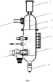
- Fig. 1 and Fig. 2 depict two views of the degassing device with integrated sensors, valves and a service pressure gauge.
- the degassing device designed for heating and/or cooling systems with a heat pump to separate bubbles of leaked flammable gaseous refrigerant from heat transfer liquid consists of an upper module 1 and a lower module 2, watertight connected together.
- modules 1 and 2 have flanges at the joint, and the watertight joint 3 is created by means of gaskets and screws. Both modules 1 and 2 are advantageously made of composite material.
- the upper module 1 is equipped with an inlet connection 4 for heat transfer liquid, and a vent valve 7 is arranged at its geometrically highest point.
- the upper module 1 and the lower module 2 are connected together to form a collection chamber for heat transfer liquid.
- a fixed separating wall 13 is arranged inside the upper module 1.
- the wall 13 is arranged perpendicular to the axis of the inlet connection 4.
- the lower module 2 is equipped with an outlet connection 5 for heat transfer liquid and a fixing bracket 6 for securing the degassing device in the heating system.
- connection for a pressure sensor 8 There is a connection for a pressure sensor 8, a connection for a temperature sensor 9, a connection for a service pressure gauge 12, a connection for a safety pressure valve 10, and a connection for a drain valve 11 arranged advantageously on the lower module 2.
- the connected drain valve 11 is advantageously designed as an anti-freeze valve, with freeze protection.
- the described degassing device for separating gas bubbles from liquid is primarily intended for removing leaked flammable refrigerant.
Landscapes
- Engineering & Computer Science (AREA)
- Chemical & Material Sciences (AREA)
- Combustion & Propulsion (AREA)
- Mechanical Engineering (AREA)
- General Engineering & Computer Science (AREA)
- Chemical Kinetics & Catalysis (AREA)
- Physics & Mathematics (AREA)
- Thermal Sciences (AREA)
- Degasification And Air Bubble Elimination (AREA)
Abstract
Description
- The invention relates to a degassing device for separating gas bubbles from liquid, particularly from heat transfer liquid in a heating and/or cooling system with a heat pump.
- The degassing process in heating systems was originally developed to separate air or its components. Air that has infiltrated the closed heat transfer liquid circuit due to leakage or malfunction is an undesirable element and must therefore be removed from the heat transfer liquid circuit.
- The simplest separator of air from liquid is, for example, a float-type vent valve for releasing air, which is usually located at the highest geographical point of the heating system.
- Another commonly used degassing device includes a liquid inlet, a liquid outlet, a collection chamber, and a liquid flow path extending from the liquid inlet through the collection chamber to the liquid outlet. Such a degassing device often includes a float-type vent valve as a component.
- Another known type of a separator is a device for degassing micro-bubbles, which typically includes at least one separating element in the collection chamber. The separating element can be a wall, a metal grid, a tube, or another suitable component designed to create, grow, and separate gas bubbles from the flow of the heat transfer liquid.
- When the liquid flow encounters the separating element after the liquid inlet, the flow slows down in the chamber, allowing gas bubbles to separate from the stream, aggregate at the bottom of the chamber, forming large bubbles that rise upwards.
- Once they reach the top of the vent valve, the aggregated bubbles press against the float of the vent valve, and the accumulated gas is expelled.
- This type of a degassing device is highly effective in removing dissolved gas from heat transfer liquid in a closed circuit. For effective separation of gas from liquid, the volume of the collection chamber needs to be relatively large.
- A compression refrigeration machine is the basis of a heating and/or cooling system with a heat pump for heating and/or cooling spaces and preparing hot water. This machine generates heat to warm heating water from the heat extracted from the external environment, while the working fluid of the compression machine circulates as a refrigerant in a counterclockwise thermodynamic cycle.
- A standard electric backup heater is currently used for degassing heat transfer liquid in such devices, which includes a collection chamber function. In the upper part an air vent valve is connected to it via a special brass connection.
- For environmental reasons, newer heat pumps no longer use safety refrigerants, they use flammable natural working fluids such as R290 and R1270, or other common, flammable refrigerants such as R32.
- Depending on the circuit and operating mode, leaks in the condenser or evaporator can lead to leakage of gaseous, flammable working fluid from the refrigerant circuit into the heat transfer liquid circuit (it is called also secondary heat pump circuit).
- In the prior state of the art, this is prevented by using double-walled heat exchangers made of stainless steel as condensers and evaporators.
- In the event of a leak, the flammable working fluid enters the space between the two walls, where it is separately extracted and subjected to additional treatment. This additional treatment can also be omitted if there is a safe path to the atmosphere, where it mixes with the air to such an extent that an ignitable mixture cannot form. The gap is usually only a few tenths of a millimeter. However, these types of constructions are expensive on one hand and impede heat transfer on the other, as the interspace acts as thermal insulation, thereby reducing achievable efficiency. Moreover, leaks can also affect both walls, including the outer one.
- For these reasons, single-walled heat exchangers (condenser, evaporator) are used again, and effective solutions for degassing heating circuits are implemented.
- To prevent dangerous concentrations of flammable refrigerant in a building, it is essential to use a suitable degassing device in the heating system; the currently used standard solution of a vent valve connected to an electric water heater cannot be used.
- The process of degassing microbubbles can also be used to separate flammable refrigerants that may have leaked from the refrigerant circuit into the heat transfer medium in heat pump systems in the event of a malfunction, provided that the associated ventilation piping does not lead into the interior of the building, but to the external environment.
- As already mentioned, for effective separation of gas from liquid, the volume of the collection chamber needs to be relatively large. It is therefore advantageous to include, where possible, additional functions in the degassing device that would otherwise have to be implemented elsewhere in the heating and/or cooling system.
- The presented invention describes a compact degassing device, suitable for degassing flammable refrigerants from heat transfer liquid, integrating several functions.
- The degassing device designed for heating and/or cooling systems with a heat pump to separate bubbles of flammable gaseous refrigerant from heat transfer liquid consists of an upper and lower module, watertight connected together.
- The upper module is equipped with a connection for heat transfer liquid inlet, and a vent valve is arranged at its geometrically highest point.
- The lower module is equipped with a connection for heat transfer liquid outlet, with water or a mixture of water with glycol used as heat transfer liquid.
- The connection of the upper and lower modules is provided to form a collection chamber for the liquid.
- Inside the upper module, a fixed separating wall is arranged.
- The separating wall is arranged in the path of the liquid flow, causing the liquid flow to hit the separating wall after the liquid enters. In the collection chamber, the flow slows down, allowing gas bubbles to separate from the stream, aggregating at the bottom of the chamber to form large bubbles that rise upwards. Once they reach the float of the air vent valve, the aggregated bubbles press against the float, causing the accumulated gas to be expelled.
- The lower module forms a larger volume of the collection chamber, making it possible to arrange connections on its walls for some functional devices, which is particularly advantageous for service purposes and/or device monitoring.
- Advantageously arranged on the lower module, there is a connection especially for a pressure sensor, temperature sensor, service pressure gauge, safety pressure relief valve, and drain valve.
- There is a drain valve advantageously arranged on the degassing device, as in the event of refrigerant leakage, it is often necessary to flush the system in order to remove any remnants of leaked refrigerant.
- There is a service pressure gauge advantageously arranged on the degassing device, providing quick access to pressure information during visual inspection of the heating device.
- The degassing device can be connected to the heat transfer medium piping either in the outdoor unit or in the indoor unit of the heat pump and secured using a fixing bracket.
- For safety when using flammable working fluids, the degassing device is most commonly located in the outdoor unit, and in this case, the drain valve can be designed as an anti-freeze valve, with freeze protection.
- The described design solution of the degassing device allows for the integration of additional functions necessary for the operation of the heating device while maximizing the use of space. Functions that would otherwise have to be implemented elsewhere in the heating device are integrated in one device.
-
Fig. 1 andFig. 2 depict two views of the degassing device with integrated sensors, valves and a service pressure gauge. - The degassing device designed for heating and/or cooling systems with a heat pump to separate bubbles of leaked flammable gaseous refrigerant from heat transfer liquid consists of an
upper module 1 and alower module 2, watertight connected together. - In the example embodiment in
Fig.1 andFig. 2 ,modules watertight joint 3 is created by means of gaskets and screws. Bothmodules - The
upper module 1 is equipped with aninlet connection 4 for heat transfer liquid, and avent valve 7 is arranged at its geometrically highest point. - The
upper module 1 and thelower module 2 are connected together to form a collection chamber for heat transfer liquid. - Inside the
upper module 1, a fixed separatingwall 13 is arranged. Thewall 13 is arranged perpendicular to the axis of theinlet connection 4. - The
lower module 2 is equipped with anoutlet connection 5 for heat transfer liquid and afixing bracket 6 for securing the degassing device in the heating system. - There is a connection for a
pressure sensor 8, a connection for atemperature sensor 9, a connection for aservice pressure gauge 12, a connection for asafety pressure valve 10, and a connection for adrain valve 11 arranged advantageously on thelower module 2. - In the case that the degassing device is arranged in the outdoor unit of the heat pump, the connected
drain valve 11 is advantageously designed as an anti-freeze valve, with freeze protection. - The described degassing device for separating gas bubbles from liquid, especially from the heat transfer liquid in a heating and/or cooling system with a heat pump, is primarily intended for removing leaked flammable refrigerant.
-
- 1 upper module
- 2 lower module
- 3 watertight joint
- 4 inlet connection
- 5 outlet connection
- 6 fixing bracket
- 7 vent valve
- 8 pressure sensor
- 9 temperature sensor
- 10 pressure relief valve
- 11 drain valve
- 12 service pressure gauge
- 13 separating wall
Claims (4)
- A degassing device designed for heating and/or cooling systems with a heat pump to separate bubbles of flammable gaseous refrigerant from heat transfer liquid,
characterized in thatit consists of an upper module (1) and a lower module (2), connected to each other by a watertight joint (3) to form a collection chamber for heat transfer liquid,the upper module (1) is equipped with an inlet connection (4) for the heat transfer liquid,the lower module (2) is equipped with an outlet connection (5) for heat transfer liquid and with a fixing bracket (6) for securing the degassing device in the heating system,inside the upper module (1), there is a fixed separating wall (13) arranged perpendicular to the axis of the inlet connection (4),and a vent valve (7) is arranged at the highest geometric point of the device,wherein the lower module (2) is equipped with a connection for a pressure sensor (8), a connection for a temperature sensor (9), a connection for a service pressure gauge (12), a connection for a safety pressure valve (10), and a connection for a drain valve (11). - The degassing device according to claim 1,
characterized in that the watertight joint (3) is created by means of gaskets and screws, and the upper and lower modules (1, 2) are made of composite material. - An outer unit of a heating system with a heat pump,
characterized in that it is equipped with the degassing device according to any of the preceding claims. - The outer unit of a heating system with a heat pump according to the claim 3,
characterized in that
the drain valve (11) connected to the degassing device is designed as an anti-freeze valve.
Applications Claiming Priority (1)
| Application Number | Priority Date | Filing Date | Title |
|---|---|---|---|
| SK135-2023A SK289182B6 (en) | 2021-03-22 | 2022-03-14 | Mobile station for pumping fluids |
Publications (3)
| Publication Number | Publication Date |
|---|---|
| EP4506626A1 true EP4506626A1 (en) | 2025-02-12 |
| EP4506626B1 EP4506626B1 (en) | 2026-01-21 |
| EP4506626C0 EP4506626C0 (en) | 2026-01-21 |
Family
ID=91969179
Family Applications (1)
| Application Number | Title | Priority Date | Filing Date |
|---|---|---|---|
| EP24190620.5A Active EP4506626B1 (en) | 2023-08-07 | 2024-07-24 | Degassing device |
Country Status (1)
| Country | Link |
|---|---|
| EP (1) | EP4506626B1 (en) |
Citations (5)
| Publication number | Priority date | Publication date | Assignee | Title |
|---|---|---|---|---|
| EP0363586B1 (en) * | 1988-09-20 | 1994-01-19 | WILO GmbH | Gas separator |
| EP1562001A1 (en) * | 2004-02-05 | 2005-08-10 | Nefit Buderus B.V. | Venting apparatus |
| DE102020103743A1 (en) * | 2020-02-13 | 2021-08-19 | Viessmann Werke Gmbh & Co Kg | Heat pump system |
| EP4047288A1 (en) * | 2021-02-18 | 2022-08-24 | Panasonic Intellectual Property Management Co., Ltd. | Heat medium circulation system |
| DE102022119835A1 (en) * | 2021-08-13 | 2023-02-16 | Viessmann Climate Solutions Se | heat pump system |
-
2024
- 2024-07-24 EP EP24190620.5A patent/EP4506626B1/en active Active
Patent Citations (5)
| Publication number | Priority date | Publication date | Assignee | Title |
|---|---|---|---|---|
| EP0363586B1 (en) * | 1988-09-20 | 1994-01-19 | WILO GmbH | Gas separator |
| EP1562001A1 (en) * | 2004-02-05 | 2005-08-10 | Nefit Buderus B.V. | Venting apparatus |
| DE102020103743A1 (en) * | 2020-02-13 | 2021-08-19 | Viessmann Werke Gmbh & Co Kg | Heat pump system |
| EP4047288A1 (en) * | 2021-02-18 | 2022-08-24 | Panasonic Intellectual Property Management Co., Ltd. | Heat medium circulation system |
| DE102022119835A1 (en) * | 2021-08-13 | 2023-02-16 | Viessmann Climate Solutions Se | heat pump system |
Also Published As
| Publication number | Publication date |
|---|---|
| EP4506626B1 (en) | 2026-01-21 |
| EP4506626C0 (en) | 2026-01-21 |
Similar Documents
| Publication | Publication Date | Title |
|---|---|---|
| US11441813B2 (en) | Indoor unit of refrigeration apparatus | |
| JP6336121B2 (en) | Refrigeration cycle equipment | |
| CN210107793U (en) | Heating, ventilation, air conditioning and refrigeration HVACR system or system with flammable refrigerant | |
| CN110709650B (en) | Heat pump utilization equipment | |
| EP3306237B1 (en) | Refrigeration cycle device and method for detecting coolant leakage | |
| CN109073306B (en) | Refrigeration cycle device | |
| JPWO2018154628A1 (en) | Air conditioner | |
| EP3001123A1 (en) | Heat reclaim for a multifunction heat pump and a muntifunction air conditioner | |
| US20190383509A1 (en) | Refrigeration cycle device and refrigeration cycle system | |
| JP2016029322A (en) | Air conditioner | |
| EP4345402A1 (en) | Heat pump cycle device | |
| US20240183360A1 (en) | Compressor lubrication supply system and compressor thereof | |
| CN110785617A (en) | Air conditioner | |
| CN106440593B (en) | Frequency converter cooling system, air conditioning unit and control method | |
| KR20190006339A (en) | Ciller unit and Chiller system including the same | |
| CN106556191A (en) | Ship refrigerating plant | |
| WO1981000756A1 (en) | A device for drawing off cooling agents from refrigeration and heating plant | |
| ES3062142T3 (en) | Degassing device | |
| EP4506626B1 (en) | Degassing device | |
| JP5918399B2 (en) | Air conditioner | |
| EP4467885A1 (en) | Indoor unit and heat pump | |
| EP4467900A1 (en) | Indoor unit and heat pump | |
| JP6565277B2 (en) | Refrigeration equipment | |
| CN118031454A (en) | Air conditioning equipment, control method and air conditioning system | |
| WO2026028026A1 (en) | Heat pump |
Legal Events
| Date | Code | Title | Description |
|---|---|---|---|
| PUAI | Public reference made under article 153(3) epc to a published international application that has entered the european phase |
Free format text: ORIGINAL CODE: 0009012 |
|
| STAA | Information on the status of an ep patent application or granted ep patent |
Free format text: STATUS: THE APPLICATION HAS BEEN PUBLISHED |
|
| AK | Designated contracting states |
Kind code of ref document: A1 Designated state(s): AL AT BE BG CH CY CZ DE DK EE ES FI FR GB GR HR HU IE IS IT LI LT LU LV MC ME MK MT NL NO PL PT RO RS SE SI SK SM TR |
|
| STAA | Information on the status of an ep patent application or granted ep patent |
Free format text: STATUS: REQUEST FOR EXAMINATION WAS MADE |
|
| GRAP | Despatch of communication of intention to grant a patent |
Free format text: ORIGINAL CODE: EPIDOSNIGR1 |
|
| STAA | Information on the status of an ep patent application or granted ep patent |
Free format text: STATUS: GRANT OF PATENT IS INTENDED |
|
| 17P | Request for examination filed |
Effective date: 20250715 |
|
| RIC1 | Information provided on ipc code assigned before grant |
Ipc: F24D 19/08 20060101AFI20250723BHEP Ipc: F24F 11/36 20180101ALI20250723BHEP Ipc: F24H 15/12 20220101ALI20250723BHEP Ipc: B01D 19/00 20060101ALI20250723BHEP Ipc: F16K 24/04 20060101ALI20250723BHEP |
|
| INTG | Intention to grant announced |
Effective date: 20250812 |
|
| GRAS | Grant fee paid |
Free format text: ORIGINAL CODE: EPIDOSNIGR3 |
|
| GRAA | (expected) grant |
Free format text: ORIGINAL CODE: 0009210 |
|
| STAA | Information on the status of an ep patent application or granted ep patent |
Free format text: STATUS: THE PATENT HAS BEEN GRANTED |
|
| AK | Designated contracting states |
Kind code of ref document: B1 Designated state(s): AL AT BE BG CH CY CZ DE DK EE ES FI FR GB GR HR HU IE IS IT LI LT LU LV MC ME MK MT NL NO PL PT RO RS SE SI SK SM TR |
|
| REG | Reference to a national code |
Ref country code: CH Ref legal event code: F10 Free format text: ST27 STATUS EVENT CODE: U-0-0-F10-F00 (AS PROVIDED BY THE NATIONAL OFFICE) Effective date: 20260121 |
|
| REG | Reference to a national code |
Ref country code: DE Ref legal event code: R096 Ref document number: 602024002164 Country of ref document: DE |
|
| REG | Reference to a national code |
Ref country code: IE Ref legal event code: FG4D |
|
| U01 | Request for unitary effect filed |
Effective date: 20260121 |
|
| U07 | Unitary effect registered |
Designated state(s): AT BE BG DE DK EE FI FR IT LT LU LV MT NL PT RO SE SI Effective date: 20260211 |
|
| REG | Reference to a national code |
Ref country code: ES Ref legal event code: FG2A Ref document number: 3062142 Country of ref document: ES Kind code of ref document: T3 Effective date: 20260408 |
|
| REG | Reference to a national code |
Ref country code: SK Ref legal event code: T3 Ref document number: E 48141 Country of ref document: SK |
|
| PG25 | Lapsed in a contracting state [announced via postgrant information from national office to epo] |
Ref country code: RS Free format text: LAPSE BECAUSE OF FAILURE TO SUBMIT A TRANSLATION OF THE DESCRIPTION OR TO PAY THE FEE WITHIN THE PRESCRIBED TIME-LIMIT Effective date: 20260421 |
|
| PG25 | Lapsed in a contracting state [announced via postgrant information from national office to epo] |
Ref country code: PL Free format text: LAPSE BECAUSE OF FAILURE TO SUBMIT A TRANSLATION OF THE DESCRIPTION OR TO PAY THE FEE WITHIN THE PRESCRIBED TIME-LIMIT Effective date: 20260121 |
|
| PG25 | Lapsed in a contracting state [announced via postgrant information from national office to epo] |
Ref country code: GR Free format text: LAPSE BECAUSE OF FAILURE TO SUBMIT A TRANSLATION OF THE DESCRIPTION OR TO PAY THE FEE WITHIN THE PRESCRIBED TIME-LIMIT Effective date: 20260422 |
|
| PG25 | Lapsed in a contracting state [announced via postgrant information from national office to epo] |
Ref country code: NO Free format text: LAPSE BECAUSE OF FAILURE TO SUBMIT A TRANSLATION OF THE DESCRIPTION OR TO PAY THE FEE WITHIN THE PRESCRIBED TIME-LIMIT Effective date: 20260421 |
|
| PG25 | Lapsed in a contracting state [announced via postgrant information from national office to epo] |
Ref country code: HR Free format text: LAPSE BECAUSE OF FAILURE TO SUBMIT A TRANSLATION OF THE DESCRIPTION OR TO PAY THE FEE WITHIN THE PRESCRIBED TIME-LIMIT Effective date: 20260121 |
|
| PG25 | Lapsed in a contracting state [announced via postgrant information from national office to epo] |
Ref country code: IS Free format text: LAPSE BECAUSE OF FAILURE TO SUBMIT A TRANSLATION OF THE DESCRIPTION OR TO PAY THE FEE WITHIN THE PRESCRIBED TIME-LIMIT Effective date: 20260521 |
|
| PGFP | Annual fee paid to national office [announced via postgrant information from national office to epo] |
Ref country code: SK Payment date: 20260629 Year of fee payment: 3 |
|
| U20 | Renewal fee for the european patent with unitary effect paid |
Year of fee payment: 3 Effective date: 20260624 |