EP4506619A1 - Combustor assembly - Google Patents
Combustor assembly Download PDFInfo
- Publication number
- EP4506619A1 EP4506619A1 EP24187014.6A EP24187014A EP4506619A1 EP 4506619 A1 EP4506619 A1 EP 4506619A1 EP 24187014 A EP24187014 A EP 24187014A EP 4506619 A1 EP4506619 A1 EP 4506619A1
- Authority
- EP
- European Patent Office
- Prior art keywords
- combustor
- head
- lug
- cowl
- combustor liner
- Prior art date
- Legal status (The legal status is an assumption and is not a legal conclusion. Google has not performed a legal analysis and makes no representation as to the accuracy of the status listed.)
- Granted
Links
Images



Classifications
-
- F—MECHANICAL ENGINEERING; LIGHTING; HEATING; WEAPONS; BLASTING
- F23—COMBUSTION APPARATUS; COMBUSTION PROCESSES
- F23R—GENERATING COMBUSTION PRODUCTS OF HIGH PRESSURE OR HIGH VELOCITY, e.g. GAS-TURBINE COMBUSTION CHAMBERS
- F23R3/00—Continuous combustion chambers using liquid or gaseous fuel
- F23R3/002—Wall structures
-
- F—MECHANICAL ENGINEERING; LIGHTING; HEATING; WEAPONS; BLASTING
- F01—MACHINES OR ENGINES IN GENERAL; ENGINE PLANTS IN GENERAL; STEAM ENGINES
- F01D—NON-POSITIVE DISPLACEMENT MACHINES OR ENGINES, e.g. STEAM TURBINES
- F01D25/00—Component parts, details, or accessories, not provided for in, or of interest apart from, other groups
- F01D25/24—Casings; Casing parts, e.g. diaphragms, casing fastenings
- F01D25/243—Flange connections; Bolting arrangements
-
- F—MECHANICAL ENGINEERING; LIGHTING; HEATING; WEAPONS; BLASTING
- F23—COMBUSTION APPARATUS; COMBUSTION PROCESSES
- F23R—GENERATING COMBUSTION PRODUCTS OF HIGH PRESSURE OR HIGH VELOCITY, e.g. GAS-TURBINE COMBUSTION CHAMBERS
- F23R3/00—Continuous combustion chambers using liquid or gaseous fuel
- F23R3/42—Continuous combustion chambers using liquid or gaseous fuel characterised by the arrangement or form of the flame tubes or combustion chambers
- F23R3/50—Combustion chambers comprising an annular flame tube within an annular casing
-
- F—MECHANICAL ENGINEERING; LIGHTING; HEATING; WEAPONS; BLASTING
- F23—COMBUSTION APPARATUS; COMBUSTION PROCESSES
- F23R—GENERATING COMBUSTION PRODUCTS OF HIGH PRESSURE OR HIGH VELOCITY, e.g. GAS-TURBINE COMBUSTION CHAMBERS
- F23R2900/00—Special features of, or arrangements for continuous combustion chambers; Combustion processes therefor
- F23R2900/00016—Retrofitting in general, e.g. to respect new regulations on pollution
-
- F—MECHANICAL ENGINEERING; LIGHTING; HEATING; WEAPONS; BLASTING
- F23—COMBUSTION APPARATUS; COMBUSTION PROCESSES
- F23R—GENERATING COMBUSTION PRODUCTS OF HIGH PRESSURE OR HIGH VELOCITY, e.g. GAS-TURBINE COMBUSTION CHAMBERS
- F23R2900/00—Special features of, or arrangements for continuous combustion chambers; Combustion processes therefor
- F23R2900/00017—Assembling combustion chamber liners or subparts
-
- F—MECHANICAL ENGINEERING; LIGHTING; HEATING; WEAPONS; BLASTING
- F23—COMBUSTION APPARATUS; COMBUSTION PROCESSES
- F23R—GENERATING COMBUSTION PRODUCTS OF HIGH PRESSURE OR HIGH VELOCITY, e.g. GAS-TURBINE COMBUSTION CHAMBERS
- F23R3/00—Continuous combustion chambers using liquid or gaseous fuel
- F23R3/42—Continuous combustion chambers using liquid or gaseous fuel characterised by the arrangement or form of the flame tubes or combustion chambers
- F23R3/60—Support structures; Attaching or mounting means
Definitions
- the present disclosure concerns a combustor assembly for a gas turbine engine, the combustor assembly comprising a combustor liner, a combustor head, a cowl and at least one fastener.
- the present disclosure also concerns a gas turbine engine comprising such a combustor assembly.
- a conventional combustor configuration includes a hoop-continuous combustor liner welded to a head structure at the front of the combustor and welded to a hoop-continuous support arm at the rear of the combustor (for a rear mounted combustor). Otherwise, the combustor liner may be welded to a hoop continuous turbine interface ring at the rear (for a front mounted).
- a combustor in which different sub-components are fastened together, as opposed to welded, may be referred to as a combustor assembly or an assembled combustor.
- Assembled combustors/combustor assemblies enable the use of different materials and manufacturing processes which, in turn, allows the introduction of higher performance features to the combustor.
- a combustor of a gas turbine engine is subject to ultimate load cases during a compressor surge event or a combustor flame-out event. Mechanical buckling of the combustor may be a concern during such load cases.
- US 2022/0082055 A1 describes a combustion chamber comprising a plurality of circumferentially arranged cassette segments coupled to a combustor head at one end and a wall section at the other end.
- the combustor head has an annular tongue structure on a mating surface.
- the tongue structure engages with a groove portion present in each of the cassettes so that when assembled the groove portions in each of the plurality of cassette segments forms a substantially continuous groove.
- EP 3054218 A1 describes a combustion chamber comprising an upstream ring structure, a downstream ring structure and a plurality of circumferentially arranged combustor liner segments.
- the combustor liner segments have a stiff frame structure which carries the structural loads, the thermal loads, surge loads and flameout loads, and the frame structure distributes loads into adjacent components.
- a combustor assembly for a gas turbine engine, the combustor assembly comprising a combustor liner, a combustor head, a cowl and a fastener, wherein the combustor liner and the cowl define a cavity; the combustor liner has an integral lug that extends into the cavity from a wall of the combustor liner; and the fastener extends into the combustor liner lug to fasten the combustor head to the combustor liner.
- the fastener may extend through the combustor liner lug to fasten the combustor head to the combustor liner.
- the lug may diverge from a profile of the wall of the combustor liner.
- the combustor head may be configured to receive and support a fuel injector.
- the fastener may be a bolt, or a rivet. It may be that the combustor head and the cowl each form part of an integral head structure.
- the fastener may extend through the combustor liner lug to fasten both the combustor head and the cowl to the combustor liner.
- the volume of the fastener is located within an external profile defined by the cowl and the combustor liner. It may be that at least 80%, at least 90%, or at least 95% of the volume of the fastener is located within the external profile. The fastener may be entirely located within the external profile.
- the combustor assembly may annularly extend around a centreline.
- the fastener may be elongate along a length direction parallel with the centreline.
- the combustor head, the cowl and the combustor liner lug each define a respective mating face.
- the mating face of the combustor liner lug may abut the mating face of the combustor head or the mating face of the cowl. It may also be that the mating face of the combustor liner lug abuts the mating face of the combustor head and the mating face of the cowl.
- the combustor assembly annularly extends around a centreline; the mating face of the combustor liner lug lies on a mating plane; and a normal to the mating plane is substantially parallel to the centreline.
- the mating face of the cowl may lie on the mating plane and/or the mating face of the combustor head may lie on the mating plane.
- a head aperture is formed between the mating faces of the cowl and the combustor head; a lug aperture is formed in the mating face of the combustor liner lug; and the fastener extends into both the head aperture and the lug aperture.
- the combustor head and the cowl together form a head structure; the combustor liner lug extends into a corresponding recess defined by the head structure; and the head aperture opens into the recess defined by the head structure.
- the combustor assembly may annularly extend around a centreline.
- the cowl and the combustor liner may each define a respective sealing face.
- the sealing face of the combustor liner may abut the sealing face of the cowl throughout the annular extent of the combustor assembly.
- Each sealing face may lie on a sealing plane; and a normal to the sealing plane may be substantially parallel with the centreline.
- the fastener may define a male thread.
- the combustor head and the cowl may be fastened with respect to the combustor liner by means of the male thread engaging a female thread.
- the female thread may be defined by or located inside the combustor liner lug.
- the female thread may be defined by a nut located outside of the combustor liner lug.
- the fastener may be configured to be withdrawn from the female thread through an access hole formed in the cowl.
- the female thread may be defined by or located inside the head aperture.
- the female thread may be defined by a nut located outside of the head aperture.
- the fastener is one of a plurality of fasteners and the combustor liner lug is one of a plurality of combustor liner lugs.
- Each combustor liner lug may extend into the cavity from the wall of the combustor liner.
- Each fastener may extend into a respective combustor liner lug to fasten the combustor head to the combustor liner.
- each fastener is elongate along a respective length direction.
- the combustor assembly may annularly extend around a centreline, and the length direction of each fastener may be substantially parallel with the centreline.
- a gas turbine engine comprising a combustor assembly in accordance with the first aspect.
- Such a gas turbine engine may comprise an engine core comprising a turbine, a combustor, a compressor, and a core shaft connecting the turbine to the compressor.
- a gas turbine engine may comprise a fan (having fan blades) located upstream of the engine core.
- the gas turbine engine may comprise a gearbox that receives an input from the core shaft and outputs drive to the fan so as to drive the fan at a lower rotational speed than the core shaft.
- the input to the gearbox may be directly from the core shaft, or indirectly from the core shaft, for example via a spur shaft and/or gear.
- the core shaft may rigidly connect the turbine and the compressor, such that the turbine and compressor rotate at the same speed (with the fan rotating at a lower speed).
- the gas turbine engine as described and/or claimed herein may have any suitable general architecture.
- the gas turbine engine may have any desired number of shafts that connect turbines and compressors, for example one, two or three shafts.
- the turbine connected to the core shaft may be a first turbine
- the compressor connected to the core shaft may be a first compressor
- the core shaft may be a first core shaft.
- the engine core may further comprise a second turbine, a second compressor, and a second core shaft connecting the second turbine to the second compressor.
- the second turbine, second compressor, and second core shaft may be arranged to rotate at a higher rotational speed than the first core shaft.
- the second compressor may be positioned axially downstream of the first compressor.
- the second compressor may be arranged to receive (for example directly receive, for example via a generally annular duct) flow from the first compressor.
- the gearbox may be arranged to be driven by the core shaft that is configured to rotate (for example in use) at the lowest rotational speed (for example the first core shaft in the example above).
- the gearbox may be arranged to be driven only by the core shaft that is configured to rotate (for example in use) at the lowest rotational speed (for example only bye the first core shaft, and not the second core shaft, in the example above).
- the gearbox may be arranged to be driven by any one or more shafts, for example the first and/or second shafts in the example above.
- the gearbox may be a reduction gearbox (in that the output to the fan is a lower rotational rate than the input from the core shaft). Any type of gearbox may be used.
- the gearbox may be a "planetary” or “star” gearbox, as described in more detail elsewhere herein.
- the gearbox may have any desired reduction ratio (defined as the rotational speed of the input shaft divided by the rotational speed of the output shaft), for example greater than 2.5, for example in the range of from 3 to 4.2, or 3.2 to 3.8, for example on the order of or at least 3, 3.1, 3.2, 3.3, 3.4, 3.5, 3.6, 3.7, 3.8, 3.9, 4, 4.1 or 4.2.
- the gear ratio may be, for example, between any two of the values in the previous sentence.
- the gearbox may be a "star” gearbox having a ratio in the range of from 3.1 or 3.2 to 3.8. In some arrangements, the gear ratio may be outside these ranges.
- a combustor may be provided axially downstream of the fan and compressor(s).
- the combustor may be directly downstream of (for example at the exit of) the second compressor, where a second compressor is provided.
- the flow at the exit to the combustor may be provided to the inlet of the second turbine, where a second turbine is provided.
- the combustor may be provided upstream of the turbine(s).
- each compressor may comprise any number of stages, for example multiple stages.
- Each stage may comprise a row of rotor blades and a row of stator vanes, which may be variable stator vanes (in that their angle of incidence may be variable).
- the row of rotor blades and the row of stator vanes may be axially offset from each other.
- each turbine may comprise any number of stages, for example multiple stages.
- Each stage may comprise a row of rotor blades and a row of stator vanes.
- the row of rotor blades and the row of stator vanes may be axially offset from each other.
- Each fan blade may be defined as having a radial span extending from a root (or hub) at a radially inner gas-washed location, or 0% span position, to a tip at a 100% span position.
- the ratio of the radius of the fan blade at the hub to the radius of the fan blade at the tip may be less than (or on the order of) any of: 0.4, 0.39, 0.38, 0.37, 0.36, 0.35, 0.34, 0.33, 0.32, 0.31, 0.3, 0.29, 0.28, 0.27, 0.26, or 0.25.
- the ratio of the radius of the fan blade at the hub to the radius of the fan blade at the tip may be in an inclusive range bounded by any two of the values in the previous sentence (i.e., the values may form upper or lower bounds), for example in the range of from 0.28 to 0.32. These ratios may commonly be referred to as the hub-to-tip ratio.
- the radius at the hub and the radius at the tip may both be measured at the leading edge (or axially forwardmost) part of the blade.
- the hub-to-tip ratio refers, of course, to the gas-washed portion of the fan blade, i.e., the portion radially outside any platform.
- the radius of the fan may be measured between the engine centreline and the tip of a fan blade at its leading edge.
- the fan diameter (which may simply be twice the radius of the fan) may be greater than (or on the order of) any of: 210 cm, 220 cm, 230 cm, 240 cm, 250 cm (around 100 inches), 260 cm, 270 cm (around 105 inches), 280 cm (around 110 inches), 290 cm (around 115 inches), 300 cm (around 120 inches), 310 cm, 320 cm (around 125 inches), 330 cm (around 130 inches), 340 cm (around 135 inches), 350 cm, 360 cm (around 140 inches), 370 cm (around 145 inches), 380 cm (around 150 inches) cm, 390 cm (around 155 inches), 400 cm, 410 cm (around 160 inches) or 420 cm (around 165 inches).
- the fan diameter may be in an inclusive range bounded by any two of the values in the previous sentence (i.e., the values may form upper or lower bounds), for example in the range of from 210 cm to 240 cm, or 250 cm to 280 cm, or 330 320 cm to 380 cm.
- the rotational speed of the fan may vary in use. Generally, the rotational speed is lower for fans with a higher diameter. Purely by way of non-limitative example, the rotational speed of the fan at cruise conditions may be less than 2600 rpm, for example less than 2500 rpm, for example less than 2300 rpm.
- the rotational speed of the fan at cruise conditions for an engine having a fan diameter in the range of from 220 210 cm to 300 cm may be in the range of from 1700 rpm to 2500 2600 rpm, for example in the range of from 1800 rpm to 2300 rpm, for example in the range of from 1900 rpm to 2100 rpm.
- the rotational speed of the fan at cruise conditions for an engine having a fan diameter in the range of from 330 cm to 380 cm may be in the range of from 1200 rpm to 2000 rpm, for example in the range of from 1300 rpm to 1800 rpm, for example in the range of from 1400 rpm to 1800 rpm.
- the fan In use of the gas turbine engine, the fan (with associated fan blades) rotates about a rotational axis. This rotation results in the tip of the fan blade moving with a velocity Utip.
- the work done by the fan blades 13 on the flow results in an enthalpy rise dH of the flow.
- a fan tip loading may be defined as dH/Utip2, where dH is the enthalpy rise (for example the 1-D average enthalpy rise) across the fan and Utip is the (translational) velocity of the fan tip, for example at the leading edge of the tip (which may be defined as fan tip radius at leading edge multiplied by angular speed).
- the fan tip loading at cruise conditions may be greater than (or on the order of) any of: 0.28, 0.29, 0.30, 0.31, 0.32, 0.33, 0.34, 0.35, 0.36, 0.37, 0.38, 0.39 or 0.4 (all values being dimensionless).
- the fan tip loading may be in an inclusive range bounded by any two of the values in the previous sentence (i.e., the values may form upper or lower bounds), for example in the range of from 0.28 to 0.31, or 0.29 to 0.3.
- Gas turbine engines in accordance with the present disclosure may have any desired bypass ratio, where the bypass ratio is defined as the ratio of the mass flow rate of the flow through the bypass duct to the mass flow rate of the flow through the core at cruise conditions.
- the bypass ratio may be greater than (or on the order of) any of the following: 10, 10.5, 11, 11.5, 12, 12.5, 13, 13.5, 14, 14.5, 15, 15.5, 16, 16.5, 17, 17.5, 18, 18.5, 19, 19.5 or 20.
- the bypass ratio may be in an inclusive range bounded by any two of the values in the previous sentence (i.e. the values may form upper or lower bounds), for example in the range of form 12 to 16, 13 to 15, or 13 to 14.
- the bypass duct may be substantially annular.
- the bypass duct may be radially outside the core engine.
- the radially outer surface of the bypass duct may be defined by a nacelle and/or a fan case.
- the overall pressure ratio of a gas turbine engine as described and/or claimed herein may be defined as the ratio of the stagnation pressure upstream of the fan to the stagnation pressure at the exit of the highest-pressure compressor (before entry into the combustor).
- the overall pressure ratio of a gas turbine engine as described and/or claimed herein at cruise may be greater than (or on the order of) any of the following: 35, 40, 45, 50, 55, 60, 65, 70, 75.
- the overall pressure ratio may be in an inclusive range bounded by any two of the values in the previous sentence (i.e. the values may form upper or lower bounds), for example in the range of from 50 to 70.
- Specific thrust of an engine may be defined as the net thrust of the engine divided by the total mass flow through the engine. At cruise conditions, the specific thrust of an engine described and/or claimed herein may be less than (or on the order of) any of the following: 110 Nkg-1s, 105 Nkg-1s, 100 Nkg-1s, 95 Nkg-1s, 90 Nkg-1s, 85 Nkg-1s or 80 Nkg-1s.
- the specific thrust may be in an inclusive range bounded by any two of the values in the previous sentence (i.e., the values may form upper or lower bounds), for example in the range of from 80 Nkg-1s to 100 Nkg-1s, or 85 Nkg-1s to 95 Nkg-1s.
- Such engines may be particularly efficient in comparison with conventional gas turbine engines.
- a gas turbine engine as described and/or claimed herein may have any desired maximum thrust.
- a gas turbine as described and/or claimed herein may be capable of producing a maximum thrust of at least (or on the order of) any of the following: 130kN, 135kN, 140kN, 145kN, 150kN, 155kN, 160kN, 170kN, 180kN, 190kN, 200kN, 250kN, 300kN, 350kN, 400kN, 450kN, 500kN, or 550kN.
- the maximum thrust may be in an inclusive range bounded by any two of the values in the previous sentence (i.e. the values may form upper or lower bounds).
- a gas turbine as described and/or claimed herein may be capable of producing a maximum thrust in the range of from 155kN to 170kN, 330kN to 420 kN, for example or 350kN to 400kN.
- the thrust referred to above may be the maximum net thrust at standard atmospheric conditions at sea level plus 15 degrees C (ambient pressure 101.3kPa, temperature 30 degrees C), with the engine static.
- the temperature of the flow at the entry to the high-pressure turbine may be particularly high.
- This temperature which may be referred to as TET
- TET may be measured at the exit to the combustor, for example immediately upstream of the first turbine vane, which itself may be referred to as a nozzle guide vane.
- the TET may be at least (or on the order of) any of the following: 1400K, 1450K, 1500K, 1520K, 1530K, 1540K, 1550K, 1600K or 1650K.
- the TET at cruise may be in an inclusive range bounded by any two of the values in the previous sentence (i.e., the values may form upper or lower bounds), for example 1530K to 1600K.
- the maximum TET in use of the engine may be, for example, at least (or on the order of) any of the following: 1700K, 1750K, 1800K, 1850K, 1900K, 1950K or 2000K.
- the maximum TET may be in an inclusive range bounded by any two of the values in the previous sentence (i.e., the values may form upper or lower bounds), for example in the range of from 1800K to 1950K, or 1900K to 2000K.
- the maximum TET may occur, for example, at a high thrust condition, for example at a maximum take-off (MTO) condition.
- MTO maximum take-off
- a fan blade and/or aerofoil portion of a fan blade described and/or claimed herein may be manufactured from any suitable material or combination of materials.
- at least a part of the fan blade and/or aerofoil may be manufactured at least in part from a composite, for example a metal matrix composite and/or an organic matrix composite, such as carbon fibre.
- at least a part of the fan blade and/or aerofoil may be manufactured at least in part from a metal, such as a titanium based metal or an aluminium based material (such as an aluminium-lithium alloy) or a steel based material.
- the fan blade may comprise at least two regions manufactured using different materials.
- the fan blade may have a protective leading edge, which may be manufactured using a material that is better able to resist impact (for example from birds, ice or other material) than the rest of the blade.
- a leading edge may, for example, be manufactured using titanium or a titanium-based alloy.
- the fan blade may have a carbon-fibre or aluminium based body (such as an aluminium lithium alloy) with a titanium leading edge.
- a fan as described and/or claimed herein may comprise a central portion, from which the fan blades may extend, for example in a radial direction.
- the fan blades may be attached to the central portion in any desired manner.
- each fan blade may comprise a fixture which may engage a corresponding slot in the hub (or disc).
- a fixture may be in the form of a dovetail that may slot into and/or engage a corresponding slot in the hub/disc in order to fix the fan blade to the hub/disc.
- the fan blades maybe formed integrally with a central portion. Such an arrangement may be referred to as a bladed disc or a bladed ring.
- any suitable method may be used to manufacture such a bladed disc or bladed ring.
- at least a part of the fan blades may be machined from a block and/or at least part of the fan blades may be attached to the hub/disc by welding, such as linear friction welding.
- variable area nozzle may allow the exit area of the bypass duct to be varied in use.
- the general principles of the present disclosure may apply to engines with or without a VAN.
- the fan of a gas turbine as described and/or claimed herein may have any desired number of fan blades, for example 14, 16, 18, 20, 22, 24 or 26 fan blades.
- cruise conditions have the conventional meaning and would be readily understood by the skilled person.
- the skilled person would immediately recognise cruise conditions to mean the operating point of the engine at mid-cruise of a given mission (which may be referred to in the industry as the "economic mission") of an aircraft to which the gas turbine engine is designed to be attached.
- mid-cruise is the point in an aircraft flight cycle at which 50% of the total fuel that is burned between top of climb and start of descent has been burned (which may be approximated by the midpoint - in terms of time and/or distance - between top of climb and start of descent).
- Cruise conditions thus define an operating point of the gas turbine engine that provides a thrust that would ensure steady state operation (i.e., maintaining a constant altitude and constant Mach Number) at mid-cruise of an aircraft to which it is designed to be attached, taking into account the number of engines provided to that aircraft. For example, where an engine is designed to be attached to an aircraft that has two engines of the same type, at cruise conditions the engine provides half of the total thrust that would be required for steady state operation of that aircraft at mid-cruise.
- cruise conditions are defined as the operating point of the engine that provides a specified thrust (required to provide - in combination with any other engines on the aircraft - steady state operation of the aircraft to which it is designed to be attached at a given mid-cruise Mach Number) at the mid-cruise atmospheric conditions (defined by the International Standard Atmosphere according to ISO 2533 at the mid-cruise altitude).
- the mid-cruise thrust, atmospheric conditions and Mach Number are known, and thus the operating point of the engine at cruise conditions is clearly defined.
- the forward speed at the cruise condition may be any point in the range of from Mach 0.7 to 0.9, for example 0.75 to 0.85, for example 0.76 to 0.84, for example 0.77 to 0.83, for example 0.78 to 0.82, for example 0.79 to 0.81, for example on the order of Mach 0.8, on the order of Mach 0.85 or in the range of from 0.8 to 0.85. Any single speed within these ranges may be part of the cruise condition. For some aircraft, the cruise conditions may be outside these ranges, for example below Mach 0.7 or above Mach 0.9.
- the cruise conditions may correspond to standard atmospheric conditions (according to the International Standard Atmosphere, ISA) at an altitude that is in the range of from 10000m to 15000m, for example in the range of from 10000m to 12000m, for example in the range of from 10400m to 11600m (around 38000 ft), for example in the range of from 10500m to 11500m, for example in the range of from 10600m to 11400m, for example in the range of from 10700m (around 35000 ft) to 11300m, for example in the range of from 10800m to 11200m, for example in the range of from 10900m to 11100m, for example on the order of 11000m.
- the cruise conditions may correspond to standard atmospheric conditions at any given altitude in these ranges.
- the cruise conditions may correspond to a forward Mach number of 0.8 and standard atmospheric conditions (according to the International Standard Atmosphere) at an altitude of 35000ft (10668m).
- an operating point of the engine provides a known required net thrust level.
- the known required net thrust level is, of course, dependent on the engine and its intended application and may be, (for example, a value in the range of from 230kN to 4035kN.) at a forward Mach number of 0.8 and standard atmospheric conditions (according to the International Standard Atmosphere) at an altitude of 38000ft (11582m).
- the cruise conditions may correspond to a forward Mach number of 0.85 and standard atmospheric conditions (according to the International Standard Atmosphere) at an altitude of 38000ft (11582m).
- the engine may provide a known required net thrust level.
- the known required net thrust level is, of course, dependent on the engine and its intended application and may be, for example, a value in the range of from 35kN to 65kN.an operating point of the engine that provides a known required thrust level (for example a value in the range of from 50kN to 65kN) at a forward Mach number of 0.85 and standard atmospheric conditions (according to the International Standard Atmosphere) at an altitude of 35000ft (10668m).
- a gas turbine engine described and/or claimed herein may operate at the cruise conditions defined elsewhere herein.
- cruise conditions may be determined by the cruise conditions (for example the mid-cruise conditions) of an aircraft to which at least one (for example 2 or 4) gas turbine engine may be mounted in order to provide propulsive thrust.
- an aircraft comprising a gas turbine engine as described and/or claimed herein.
- the aircraft according to this aspect is the aircraft for which the gas turbine engine has been designed to be attached. Accordingly, the cruise conditions according to this aspect correspond to the mid-cruise of the aircraft, as defined elsewhere herein.
- a method of operating a gas turbine engine as described and/or claimed herein may be at the cruise conditions as defined elsewhere herein (for example in terms of the thrust, atmospheric conditions and Mach Number).
- a method of operating an aircraft comprising a gas turbine engine as described and/or claimed herein.
- the operation according to this aspect may include (or may be) operation at the mid-cruise of the aircraft, as defined elsewhere herein.
- FIG. 1 illustrates a gas turbine engine 10 having a principal rotational axis 9.
- the engine 10 comprises an air intake 12 and a propulsive fan 23 that generates two airflows: a core airflow A and a bypass airflow B.
- the gas turbine engine 10 comprises a core 11 that receives the core airflow A.
- the engine core 11 comprises, in axial flow series, a low-pressure compressor 14, a high-pressure compressor 15, combustion equipment 16, a high-pressure turbine 17, a low-pressure turbine 19 and a core exhaust nozzle 20.
- a nacelle 21 surrounds the gas turbine engine 10 and defines a bypass duct 22 and a bypass exhaust nozzle 18.
- the bypass airflow B flows through the bypass duct 22.
- the fan 23 is attached to and driven by the low-pressure turbine 19 via a shaft 26 and an epicyclic gearbox 30.
- the core airflow A is accelerated and compressed by the low-pressure compressor 14 and directed into the high-pressure compressor 15 where further compression takes place.
- the compressed air exhausted from the high-pressure compressor 15 is directed into the combustion equipment 16 where it is mixed with fuel and the mixture is combusted.
- the resultant hot combustion products then expand through, and thereby drive, the high pressure and low-pressure turbines 17, 19 before being exhausted through the nozzle 20 to provide some propulsive thrust.
- the high-pressure turbine 17 drives the high-pressure compressor 15 by a suitable interconnecting shaft 27.
- the fan 23 generally provides the majority of the propulsive thrust.
- the epicyclic gearbox 30 is a reduction gearbox.
- FIG. 2 An exemplary arrangement for a geared fan gas turbine engine 10 is shown in Figure 2 .
- the low-pressure turbine 19 (see Figure 1 ) drives the shaft 26, which is coupled to a sun wheel, or sun gear, 28 of the epicyclic gear arrangement 30.
- a sun wheel, or sun gear, 28 of the epicyclic gear arrangement 30 Radially outwardly of the sun gear 28 and intermeshing therewith is a plurality of planet gears 32 that are coupled together by a planet carrier 34.
- the planet carrier 34 constrains the planet gears 32 to process around the sun gear 28 in synchronicity whilst enabling each planet gear 32 to rotate about its own axis.
- the planet carrier 34 is coupled via linkages 36 to the fan 23 in order to drive its rotation about the engine axis 9.
- an annulus or ring gear 38 Radially outwardly of the planet gears 32 and intermeshing therewith is an annulus or ring gear 38 that is coupled, via linkages 40, to a stationary supporting structure 24.
- low pressure turbine and “low pressure compressor” as used herein may be taken to mean the lowest pressure turbine stages and lowest pressure compressor stages (i.e. not including the fan 23) respectively and/or the turbine and compressor stages that are connected together by the interconnecting shaft 26 with the lowest rotational speed in the engine (i.e. not including the gearbox output shaft that drives the fan 23).
- the "low pressure turbine” and “low pressure compressor” referred to herein may alternatively be known as the "intermediate pressure turbine” and “intermediate pressure compressor”. Where such alternative nomenclature is used, the fan 23 may be referred to as a first, or lowest pressure, compression stage.
- the epicyclic gearbox 30 is shown by way of example in greater detail in Figure 3 .
- Each of the sun gear 28, planet gears 32 and ring gear 38 comprise teeth about their periphery to intermesh with the other gears. However, for clarity only exemplary portions of the teeth are illustrated in Figure 3 .
- Practical applications of a planetary epicyclic gearbox 30 generally comprise at least three planet gears 32.
- the epicyclic gearbox 30 illustrated by way of example in Figures 2 and 3 is of the planetary type, in that the planet carrier 34 is coupled to an output shaft via linkages 36, with the ring gear 38 fixed.
- the epicyclic gearbox 30 may be a star arrangement, in which the planet carrier 34 is held fixed, with the ring (or annulus) gear 38 allowed to rotate. In such an arrangement the fan 23 is driven by the ring gear 38.
- the gearbox 30 may be a differential gearbox in which the ring gear 38 and the planet carrier 34 are both allowed to rotate.
- any suitable arrangement may be used for locating the gearbox 30 in the engine 10 and/or for connecting the gearbox 30 to the engine 10.
- the connections (such as the linkages 36, 40 in the Figure 2 example) between the gearbox 30 and other parts of the engine 10 (such as the input shaft 26, the output shaft and the fixed structure 24) may have any desired degree of stiffness or flexibility.
- any suitable arrangement of the bearings between rotating and stationary parts of the engine may be used, and the disclosure is not limited to the exemplary arrangement of Figure 2 .
- the gearbox 30 has a star arrangement (described above)
- the skilled person would readily understand that the arrangement of output and support linkages and bearing locations would typically be different to that shown by way of example in Figure 2 .
- the present disclosure extends to a gas turbine engine having any arrangement of gearbox styles (for example star or planetary), support structures, input and output shaft arrangement, and bearing locations.
- gearbox styles for example star or planetary
- support structures for example star or planetary
- input and output shaft arrangement for example star or planetary
- bearing locations for example star or planetary
- the gearbox may drive additional and/or alternative components (e.g. the intermediate pressure compressor and/or a booster compressor).
- additional and/or alternative components e.g. the intermediate pressure compressor and/or a booster compressor.
- gas turbine engines to which the present disclosure may be applied may have alternative configurations.
- such engines may have an alternative number of compressors and/or turbines and/or an alternative number of interconnecting shafts.
- the gas turbine engine shown in Figure 1 has a split flow nozzle 18, 20 meaning that the flow through the bypass duct 22 has its own nozzle 18 that is separate to and radially outside the core engine nozzle 20.
- this is not limiting, and any aspect of the present disclosure may also apply to engines in which the flow through the bypass duct 22 and the flow through the core 11 are mixed, or combined, before (or upstream of) a single nozzle, which may be referred to as a mixed flow nozzle.
- One or both nozzles may have a fixed or variable area.
- the described example relates to a turbofan engine, the disclosure may apply, for example, to any type of gas turbine engine, such as an open rotor (in which the fan stage is not surrounded by a nacelle) or turboprop engine, for example.
- the gas turbine engine 10 may not comprise a gearbox 30.
- the geometry of the gas turbine engine 10, and components thereof, is defined by a conventional axis system, comprising an axial direction (which is aligned with the rotational axis 9), a radial direction (in the bottom-to-top direction in Figure 1 ), and a circumferential direction (perpendicular to the page in the Figure 1 view).
- the axial, radial and circumferential directions are mutually perpendicular.
- the combustion equipment 16 will now be described in further detail with reference to Figures 4 to 8 .
- a coordinate system is shown on each of Figures 4 to 8 .
- the coordinate system specifies an axial direction 402, a radial direction 404 and a circumferential direction 406 of the combustor assembly 160.
- the coordinate system is defined such that, when the combustor assembly 160 is incorporated within the gas turbine engine 10, the axial direction 402 is parallel to the axial direction of the gas turbine engine (and therefore the rotational axis 9), the radial direction 404 is parallel to a radial direction of the gas turbine engine 10 and the circumferential direction 406 corresponds to the circumferential direction of the gas turbine engine 10.
- FIG 4 is a more detailed cross-sectional view of the combustion equipment 16 shown by Figures 1 and 2 .
- the combustion equipment 16 annularly extends around a centreline 9'.
- the combustion equipment 16 includes a combustor assembly 160 comprising a combustor liner 59, a head structure 44 and a fastener 70, 70'.
- Compressor outlet guide vanes 39 and turbine nozzle guide vanes 52 are shown by Figure 4 in positional relation to the combustion equipment 16.
- the fastener 70, 70' is one of a plurality of such fasteners 70, 70'.
- the combustor assembly 160 may comprise only one fastener 70, 70' as described herein.
- the combustor liner 59 includes a radially inner annular wall structure 41 and a radially outer annular wall structure 42.
- the upstream end of the radially inner annular wall structure 41 is secured to the head structure 44 and the upstream end of the radially outer annular wall structure 42 is secured to the head structure 44.
- the head structure 44 comprises a combustor head 43 (which may also be referred to as a meterpanel 43), a heat shield 45 and a cowl 47.
- the cowl 47 is positioned axially upstream of and secured to the combustor head 43.
- the combustor liner 59 and the cowl 47 together define a cavity 49 within the combustor assembly 160.
- the combustor liner 59 and the head structure 44 define a combustion chamber 49' within the combustor assembly 160.
- the combustion chamber 49' is a part of the cavity 49 which is generally downstream of the head structure 44.
- the combustor assembly 160 annularly extends around the centreline 9', such that the cavity 49 defined by the combustor liner 59 and the cowl 47 is an annular cavity 49.
- the heat shield 45 is positioned axially downstream of and secured to the combustor head 43 to protect the combustor head 43 from combustion gases in the combustion chamber 49'.
- the heat shield 45 is entirely located within the cavity 49 defined by the combustor liner 59 and the cowl 47.
- the plurality of fasteners 70, 70' includes at least one radially inner fastener 70' and at least one radially outer fastener 70.
- the combustion equipment 16 is provided with a plurality of fuel injectors 48, arranged to supply fuel into the combustion chamber 49' during operation of the gas turbine engine 10.
- the combustor head 43 has a plurality of circumferentially spaced apertures 46, with each aperture 46 receiving and accommodating a respective one of the plurality of fuel injectors 48.
- the heat shield 45 and the cowl 47 also each have a plurality of circumferentially spaced apertures and each aperture in the heat shield 45 and the cowl 47 is aligned with a corresponding aperture 46 in the combustor head 43.
- a plurality of circumferentially distributed compressor outlet guide vanes 39 are positioned axially upstream of the combustion equipment 16 and are arranged to direct the compressed air from the high-pressure compressor 15 into the annular combustion equipment 16.
- the airflow between the compressor outlet guide vanes 39 and the turbine nozzle guide vanes 52 within the annular combustion equipment 16 may be referred to as the combustor annulus airflow.
- a first portion of the combustor annulus airflow is directed in use into the combustion chamber 49' though at least one air passageway formed in the fuel injector 48, and a second portion of the combustor annulus airflow is directed around the combustor assembly 160.
- a plurality of circumferentially distributed turbine nozzle guide vanes 52 are positioned axially downstream of the combustion equipment 16 and are arranged to direct the hot gases from the annular combustion equipment 16 into the high-pressure turbine 17.
- the radially outer annular wall structure 42 comprises at least one radially outer mixing port 100 and the radially inner wall structure 41 comprises at least one radially inner mixing port 102.
- Each mixing port 100, 102 is configured to facilitate and promote influx of the second portion of the combustor annulus airflow into the combustion chamber 49' in which it mixes with the first portion of the combustor annulus airflow for improved combustion of gases (e.g., fuel and air) within the combustion chamber 49'.
- gases e.g., fuel and air
- the radially outer annular wall structure 42 may not comprise a radially outer mixing port 100 and/or the radially inner wall structure 41 may not comprise a radially inner mixing port 102.
- the annular combustion equipment 16 is positioned radially between a radially outer combustion equipment casing 110 and a radially inner combustion equipment casing 112.
- the region between the radially outer combustion equipment casing 110 and the combustion equipment 16 may be referred to as an outer annulus, while the region between the radially inner combustion equipment casing 112 and the combustion equipment 16 may be referred to as an inner annulus.
- the upstream end of the radially inner combustion equipment casing 112 is removably secured to the upstream end of the radially outer combustion equipment casing 110.
- a flange (not shown) at the upstream end of the radially inner combustion equipment casing 112 may be removably secured to a flange (not shown) at the upstream end of the radially outer combustion equipment casing 110 by suitable fasteners, e.g., bolts or rivets, passing through the flanges.
- suitable fasteners e.g., bolts or rivets.
- the downstream end of the radially inner combustion equipment casing 112 is removably secured to the radially inner ends of the turbine nozzle guide vanes 52.
- flanges (not shown) on the turbine nozzle guide vanes 52 may be removably secured to a flange (not shown) at the downstream end the radially inner combustion equipment casing 112 by suitable fasteners passing through the flanges.
- a radially inner downstream ring structure 54 is mounted on the radially inner combustion equipment casing 112 and a radially outer downstream ring structure 56 is mounted on the radially outer combustion equipment casing 110.
- the radially inner annular wall structure 41 of the annular combustion equipment 16 and the radially outer annular wall structure 42 of the annular combustion equipment 16 comprise a plurality of circumferentially distributed combustor liner segments 58 and 60, respectively.
- the combustor liner segments 58, 60 extend the full axial, longitudinal, length of the annular combustion equipment 16.
- the combustor liner segments 58, 60 may be incorporated and/or affixed within the combustor assembly 160 using tongue and groove structures as described in US 2022/0082055 A1 with respect to FIGs. 10, 11 and 12 thereof.
- the combustor liner 59 includes at least one integral lug 80, 80'.
- the or each integral lug extends away from a wall (e.g., the radially inner wall structure 41 or the radially outer wall structure 42) of the combustor liner 59 and into the cavity 49 defined by the cowl 47 and the combustor liner 59.
- the plurality of integral lugs 80 includes at least one radially inner integral lug 80' and at least one radially outer integral lug 80, with each fastener 70, 70' extending through a respective integral lug 80, 80' to fasten the head structure 44 (e.g., at least the combustor head 43 or both the combustor head 43 and the cowl 47) to the combustor liner 59.
- head structure 44 e.g., at least the combustor head 43 or both the combustor head 43 and the cowl 47
- the radially outer lug 80 extends from the radially outer wall structure 42 into the cavity 49 (e.g., extending inwardly from a profile of the radially outer wall structure) and the radially outer fastener 70 extends into (e.g., through, as in the example of Figures 4 to 7 ) the radially outer lug 80 to fasten the head structure 44 to the combustor liner 59.
- the radially inner lug 80' extends from the radially inner wall structure 41 into the cavity 49 (e.g., extending inwardly from a profile of the radially inner wall structure 41) and the radially inner fastener extends through the radially inner lug 80' to fasten the head structure 44 to the combustor liner 59.
- the combustor head 43 and the cowl 47 are not integral components and are instead fastened to one another (e.g., with respect to one another) by the or each fastener 70, 70'. Nevertheless, in some examples, a variant combustor head 43 and cowl 47 may be integral with one another and hence form an integral head structure 44.
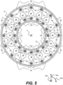
- Figure 5 shows a partially cut-away view of an annular extent of the example combustor assembly 160 around the centreline 9' in the direction indicated by A on Figure 4 , with like reference signs indicating common features.
- the side of the head structure 44 viewable in the direction indicated by A in Figure 4 may be referred to as a cold side of the head structure 44.
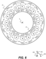
- Figure 6 shows a partially cut-away view of the annular extent of the example combustor assembly around the centreline 9' in the direction indicated by B on Figure 4 , with like reference signs denoting common features.
- the side of the head structure 44 viewable in the direction indicated by B may be referred to as a hot side of the head structure 44.
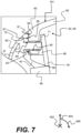
- Figure 7 shows a detail cross-sectional view of the example combustor assembly 106 in the region indicated by C on Figure 4 .
- FIG. 5 The circumferential arrangement of combustor liner segments 58 and 60 of the annular combustion equipment 16 is best shown in Figure 5 .
- Other suitable numbers of combustor liner segments 58 and 60 may be used, e.g. two, three, four, five, six, eight, ten, twelve, fourteen, eighteen or twenty, and the number of combustor liner segments 58 may be the same as or different to the number of combustor liner segments 60.
- each of the combustor liner segments extends through the same angle. However, it is also possible to arrange the combustor liner segments to extend through different angles. Further features of Figure 5 will be discussed in further detail below.
- each lug 80, 80' diverges from a profile of the respective wall 41, 42 of the combustor liner 59.
- the combustor liner 59 comprises a locally increased radial thickness at the location of each lug 80, 80' to project into the cavity 49.
- each lug 80, 80' has a limited extent along the axial direction 402 (as best shown by Figures 4 and 7 ) and a limited extent along the circumferential direction 406, and therefore also has a limited extent around the centreline 9' (as best shown by Figures 5 and 6 , by reference to the locations of the fasteners 70, 70' which correspond to the lugs).
- each lug 80, 80' extends into and generally conforms to the shape of a corresponding recess 86 defined by the head structure 44 (as best shown by Figure 7 ).
- the lugs 80, 80' and the recesses 86 thereby cooperate to radially and circumferentially align the head structure 44 and the combustor liner 59 for effective fastening by the fasteners 70, 70'.
- each recess 86 has a limited extent along the axial direction 402 and a limited extend along the circumferential direction 406, and therefore a limited extent around the centreline 9'.
- the combustor liner 59 can include only one radially outer integral lug 80 and only one radially inner integral lug 80', In such examples, each lug 80, 80' has a limited extent along the axial direction 402 (like that shown by Figures 4 and 7 ) but extends around the annular extent of the combustor assembly 106 to form a continuous annular integral lug (a flange).
- a majority of a volume of each fastener 70, 70' is located within an external profile 161 defined by the cowl 47 and the combustor liner 59 as assembled.
- more than 70% of the volume of each fastener 70, 70' is located within the external profile 161.
- more than 80%, more than 90%, or more than 95% of the volume of each fastener 70, 70' may be located within the external profile 161.
- 100% of the volume of each fastener 70, 70' may be located within the external profile 161 such that each fastener 70, 70' is entirely located within the external profile 161.
- the lugs and fasteners joining the combustor liner to the head structure were found to introduce (e.g., instigate) aerodynamic wakes into combustor annulus flow within the outer and inner annuli.
- aerodynamic wakes are associated with (e.g., may cause) changes in the dynamic pressure around the mixing ports downstream of the lugs and fasteners, and so may result in reduced air influx into the combustion chamber through the mixing ports. This may subsequently adversely affect the mixing of combustion gases within the combustion chamber.
- a combustor assembly 160 in accordance with the present disclosure provides improved overall performance characteristics to the combustion equipment 16 by reducing the likelihood or influence of significant aerodynamic wakes being introduced into the combustor annulus flow within the inner and outer annuli (and hence increasing air influx into the combustion chamber 49' through the mixing ports) while being able to adequately resist mechanical buckling in a variety of load cases.
- the combustor head 43 defines a plurality of combustor head mating faces 83, 83'
- the cowl defines a plurality of cowl mating faces 87, 87'
- each lug 80, 80' defines a lug mating face 89, 89' (see Figure 5 ).
- the lug mating faces 89, 89' are shown using dotted lines in Figure 5
- the combustor head mating faces 83, 83' and the cowl mating faces 87, 87' are shown using dotted lines in Figure 6 .
- each combustor head mating face 83, 83' and the respective cowl mating face 87, 87' are shown as separate regions in Figure 6 and a head aperture 84 is formed between the mating faces 83, 83', 87, 87' of the cowl 47 and the combustor head 43 (as best shown in Figure 7 ).
- the head aperture 84 opens into the corresponding recess 86 defined by the head structure 44.
- Each mating face 83, 83', 87, 87', 89, 89' has a generally planar form.
- each mating face 83, 83', 87, 87', 89, 89' may be planar and may lie on a mating plane having a normal which is substantially parallel with the centreline 9'. For this reason, each mating face may be referred to as an axial mating face.
- each combustor head mating face 83, 83' and the respective cowl mating face 87, 87' may together form a unified head structure mating face, and so the head aperture 84 may be formed through the unified head structure mating face (corresponding to the mating faces 83, 83', 87, 87' of the cowl 47 and the combustor head 43 described above).
- each lug mating face 89, 89' abuts a corresponding combustor head mating face 83, 83' and a corresponding cowl mating face 87, 87'.
- a lug aperture 85 is formed within each combustor liner lug 80, 80'.
- Each lug aperture 85 aligns with a corresponding head aperture 84 as described above, and one of the fasteners 70, 70' extends into (e.g., through) each lug aperture 85 and the corresponding head aperture 84 to fasten both the combustor head 43 and the cowl 47 to (e.g., with respect to) the combustor liner 59.
- each fastener 70, 70' is elongate along a length direction which is parallel to the centreline 9'. Accordingly, a midline of each aperture 85, 84 is also parallel to the centreline 9'.
- cowl 47 defines a radially outer cowl sealing face 97 and a radially inner cowl sealing face 97' (best shown in Figures 5-7 ), each of which extend around the annular extent of the combustor assembly 106 (as best shown in Figures 5 and 6 ).
- the combustor liner 59 defines a corresponding radially outer combustor liner sealing face 99 and a corresponding radially inner combustor liner sealing face 99, each of which also extend around the annular extent of the combustor assembly 106 and abuts the opposing cowl sealing face 97, 97' throughout the annular extent of the combustor assembly 106, to seal the cavity 49 proximal to the heat shield 45 and the fuel injector 48.
- the radial extent of the opposing sealing faces may be considered to be the extent to which they are radially coextensive for abutment.
- Both sealing faces 97, 99 have a generally planar form.
- the sealing faces 97, 97', 99, 99' are generally planar and lie on a sealing plane having a normal which is substantially parallel with the centreline 9'. Accordingly, each sealing face may be referred to as an axial sealing face.
- Each fastener 70, 70' may be, for example, a bolt or a rivet.
- each fastener 70, 70' may be a bolt defining a male thread, and may be configured to fasten the combustor head 43 and the cowl 47 to (e.g., with respect to) the combustor liner 59 by means of the male thread engaging a female thread.
- the male thread of each fastener 70, 70' engages a female thread which is defined by an insert 71 located inside the respective lug aperture 85 to provide a spigot-type fit, as best shown by Figure 7 .
- such an insert 71 may not be provided and each female thread may be defined by the lug aperture 85 itself.
- each female thread may be defined by a nut located either inside or outside of the lug aperture 85and/or outside of the combustor liner lug, 80, 80'. Threaded engagement of the fastener 70, 70' and the components of the combustor assembly 160 facilitates easy assembly and disassembly and is therefore associated with an increase ease of manufacturing and maintenance of the combustor assembly 160.
- each access hole 90, 90' is radially and circumferentially aligned with a corresponding head aperture 84 and a corresponding lug aperture 85. Further, each access hole 90, 90' is dimensioned so that the fastener 70, 70' which extends into (e.g., through) the corresponding apertures 84 is insertable and withdrawable into the apertures from the cold side of the head structure 44 through the access hole 90, 90'.
- Figure 8 shows a detail cross-sectional view of a variant example combustor assembly 160 in a region corresponding to that indicated by C on Figure 4 .
- the example combustor assembly 160 shown in Figure 8 is generally similar to the example combustor assembly 160 described above with respect to Figures 4 to 7 , with like reference numerals indicating common or similar features.
- each fastener 70, 70' extends into the lug aperture 85 and the head aperture 84 from a direction which opposes the direction in which each fastener 70, 70' extends into the lug aperture 85 and the head aperture 84 in the example combustor assembly 160 of Figures 4 to 7 .
- each fastener 70, 70' is insertable into the apertures from the hot side of the head structure 44. Further, the male thread of each fastener 70, 70' engages a female thread which is defined by an insert 71 located inside the respective head aperture 84. In further examples, such an insert 71 may not be provided and each female thread may be defined by the head aperture 84 itself. In yet further examples, such an insert 71 may not be provided and each female thread may be defined by a nut located either inside or outside of the head aperture 84 and/or outside of the head structure 44.
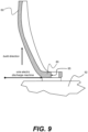
- the combustor liner 59 (e.g., the combustor liner segment(s) 58, 60) may be manufactured using additive layer manufacture (ALM) as will be further described with respect to Figure 9 .
- ALM additive layer manufacture
- 'Laser Beam Powder Bed Fusion', 'Electron beam powder bed fusion', 'binder jetting' or 'nanoparticle jetting' ALM techniques may be employed.
- the lug aperture 85 and optionally the female thread may also be printed as part of the manufacturing of the combustor liner 59.
- the combustor liner 59 may be cast or manufactured using a CNC process. In both cases the lug aperture(s) 85 in the combustor liners 59 may be machined out.
- each fastener 70, 70' being parallel to the centreline 9' generally places the components of the combustor assembly 160 (e.g., each aperture 85, 84) in a more optimal orientation for manufacturing, especially if an ALM manufacturing process is used.
- such an orientation may reduce a requirement to machine the apertures 85, 84 and/or other components of the combustor assembly 160 after the ALM process is complete.
- the aperture 85, 84 is placed in an improved orientation for a high-quality and repeatable surface finish of the female thread during the ALM process.
- the axial mating face(s) may be produced by a wire electro discharge machine process to remove the combustor liner segment 58, 60 from a build plate 92 as shown in Figure 9 .
- the combustor liner segment 58, 60 is manufactured using an ALM process.
- the combustor liner segment 58, 60 may be built up in a direction perpendicular and away from the surface of the build plate 92.
- combustor liner segment 58, 60 may be built at any suitable angle, however, this may require further machining of the combustor liner segment 58, 60 prior to incorporation within the combustor assembly 160.
- Using such a method allows for the height of the cut off from the build plate to be accurately determined. This allows for a greater degree of control and accuracy of the build of the combustor liner 59 structures. This has a further advantage of reducing the axial tolerance stack and therefore the fuel spray nozzle penetration into the combustion chamber 49'.
Landscapes
- Engineering & Computer Science (AREA)
- Mechanical Engineering (AREA)
- General Engineering & Computer Science (AREA)
- Chemical & Material Sciences (AREA)
- Combustion & Propulsion (AREA)
- Structures Of Non-Positive Displacement Pumps (AREA)
- Turbine Rotor Nozzle Sealing (AREA)
Abstract
Description
- The present disclosure concerns a combustor assembly for a gas turbine engine, the combustor assembly comprising a combustor liner, a combustor head, a cowl and at least one fastener. The present disclosure also concerns a gas turbine engine comprising such a combustor assembly.
- A conventional combustor configuration includes a hoop-continuous combustor liner welded to a head structure at the front of the combustor and welded to a hoop-continuous support arm at the rear of the combustor (for a rear mounted combustor). Otherwise, the combustor liner may be welded to a hoop continuous turbine interface ring at the rear (for a front mounted). A combustor in which different sub-components are fastened together, as opposed to welded, may be referred to as a combustor assembly or an assembled combustor. Assembled combustors/combustor assemblies enable the use of different materials and manufacturing processes which, in turn, allows the introduction of higher performance features to the combustor. Typically, a combustor of a gas turbine engine is subject to ultimate load cases during a compressor surge event or a combustor flame-out event. Mechanical buckling of the combustor may be a concern during such load cases.
-
US 2022/0082055 A1 describes a combustion chamber comprising a plurality of circumferentially arranged cassette segments coupled to a combustor head at one end and a wall section at the other end. The combustor head has an annular tongue structure on a mating surface. The tongue structure engages with a groove portion present in each of the cassettes so that when assembled the groove portions in each of the plurality of cassette segments forms a substantially continuous groove.EP 3054218 A1 describes a combustion chamber comprising an upstream ring structure, a downstream ring structure and a plurality of circumferentially arranged combustor liner segments. The combustor liner segments have a stiff frame structure which carries the structural loads, the thermal loads, surge loads and flameout loads, and the frame structure distributes loads into adjacent components. - However, each of these prior-art arrangements have associated disadvantages. It is desired to provide an improved combustor assembly which is able to adequately resist mechanical buckling in a variety of load cases whilst providing good overall performance characteristics.
- According to a first aspect of the present disclosure, there is provided a combustor assembly for a gas turbine engine, the combustor assembly comprising a combustor liner, a combustor head, a cowl and a fastener, wherein the combustor liner and the cowl define a cavity; the combustor liner has an integral lug that extends into the cavity from a wall of the combustor liner; and the fastener extends into the combustor liner lug to fasten the combustor head to the combustor liner.
- The fastener may extend through the combustor liner lug to fasten the combustor head to the combustor liner. The lug may diverge from a profile of the wall of the combustor liner. The combustor head may be configured to receive and support a fuel injector. The fastener may be a bolt, or a rivet. It may be that the combustor head and the cowl each form part of an integral head structure.
- The fastener may extend through the combustor liner lug to fasten both the combustor head and the cowl to the combustor liner.
- It may be that at least 70 % of the volume of the fastener is located within an external profile defined by the cowl and the combustor liner. It may be that at least 80%, at least 90%, or at least 95% of the volume of the fastener is located within the external profile. The fastener may be entirely located within the external profile.
- The combustor assembly may annularly extend around a centreline. The fastener may be elongate along a length direction parallel with the centreline.
- It may be that the combustor head, the cowl and the combustor liner lug each define a respective mating face. The mating face of the combustor liner lug may abut the mating face of the combustor head or the mating face of the cowl. It may also be that the mating face of the combustor liner lug abuts the mating face of the combustor head and the mating face of the cowl.
- It may be that: the combustor assembly annularly extends around a centreline; the mating face of the combustor liner lug lies on a mating plane; and a normal to the mating plane is substantially parallel to the centreline.
- The mating face of the cowl may lie on the mating plane and/or the mating face of the combustor head may lie on the mating plane.
- It may be that: a head aperture is formed between the mating faces of the cowl and the combustor head; a lug aperture is formed in the mating face of the combustor liner lug; and the fastener extends into both the head aperture and the lug aperture.
- It may be that: the combustor head and the cowl together form a head structure; the combustor liner lug extends into a corresponding recess defined by the head structure; and the head aperture opens into the recess defined by the head structure.
- The combustor assembly may annularly extend around a centreline. The cowl and the combustor liner may each define a respective sealing face. The sealing face of the combustor liner may abut the sealing face of the cowl throughout the annular extent of the combustor assembly. Each sealing face may lie on a sealing plane; and a normal to the sealing plane may be substantially parallel with the centreline.
- The fastener may define a male thread. The combustor head and the cowl may be fastened with respect to the combustor liner by means of the male thread engaging a female thread.
- The female thread may be defined by or located inside the combustor liner lug. The female thread may be defined by a nut located outside of the combustor liner lug. The fastener may be configured to be withdrawn from the female thread through an access hole formed in the cowl.
- The female thread may be defined by or located inside the head aperture. The female thread may be defined by a nut located outside of the head aperture.
- It may be that the fastener is one of a plurality of fasteners and the combustor liner lug is one of a plurality of combustor liner lugs. Each combustor liner lug may extend into the cavity from the wall of the combustor liner. Each fastener may extend into a respective combustor liner lug to fasten the combustor head to the combustor liner.
- It may be that each fastener is elongate along a respective length direction. The combustor assembly may annularly extend around a centreline, and the length direction of each fastener may be substantially parallel with the centreline.
- According to a second aspect of the present disclosure, there is provided a gas turbine engine comprising a combustor assembly in accordance with the first aspect.
- As noted elsewhere herein, the present disclosure may relate to a gas turbine engine. Such a gas turbine engine may comprise an engine core comprising a turbine, a combustor, a compressor, and a core shaft connecting the turbine to the compressor. Such a gas turbine engine may comprise a fan (having fan blades) located upstream of the engine core.
- Arrangements of the present disclosure may be particularly, although not exclusively, beneficial for fans that are driven via a gearbox. Accordingly, the gas turbine engine may comprise a gearbox that receives an input from the core shaft and outputs drive to the fan so as to drive the fan at a lower rotational speed than the core shaft. The input to the gearbox may be directly from the core shaft, or indirectly from the core shaft, for example via a spur shaft and/or gear. The core shaft may rigidly connect the turbine and the compressor, such that the turbine and compressor rotate at the same speed (with the fan rotating at a lower speed).
- The gas turbine engine as described and/or claimed herein may have any suitable general architecture. For example, the gas turbine engine may have any desired number of shafts that connect turbines and compressors, for example one, two or three shafts. Purely by way of example, the turbine connected to the core shaft may be a first turbine, the compressor connected to the core shaft may be a first compressor, and the core shaft may be a first core shaft. The engine core may further comprise a second turbine, a second compressor, and a second core shaft connecting the second turbine to the second compressor. The second turbine, second compressor, and second core shaft may be arranged to rotate at a higher rotational speed than the first core shaft.
- In such an arrangement, the second compressor may be positioned axially downstream of the first compressor. The second compressor may be arranged to receive (for example directly receive, for example via a generally annular duct) flow from the first compressor.
- The gearbox may be arranged to be driven by the core shaft that is configured to rotate (for example in use) at the lowest rotational speed (for example the first core shaft in the example above). For example, the gearbox may be arranged to be driven only by the core shaft that is configured to rotate (for example in use) at the lowest rotational speed (for example only bye the first core shaft, and not the second core shaft, in the example above). Alternatively, the gearbox may be arranged to be driven by any one or more shafts, for example the first and/or second shafts in the example above.
- The gearbox may be a reduction gearbox (in that the output to the fan is a lower rotational rate than the input from the core shaft). Any type of gearbox may be used. For example, the gearbox may be a "planetary" or "star" gearbox, as described in more detail elsewhere herein. The gearbox may have any desired reduction ratio (defined as the rotational speed of the input shaft divided by the rotational speed of the output shaft), for example greater than 2.5, for example in the range of from 3 to 4.2, or 3.2 to 3.8, for example on the order of or at least 3, 3.1, 3.2, 3.3, 3.4, 3.5, 3.6, 3.7, 3.8, 3.9, 4, 4.1 or 4.2. The gear ratio may be, for example, between any two of the values in the previous sentence. Purely by way of example, the gearbox may be a "star" gearbox having a ratio in the range of from 3.1 or 3.2 to 3.8. In some arrangements, the gear ratio may be outside these ranges.
- In any gas turbine engine as described and/or claimed herein, a combustor may be provided axially downstream of the fan and compressor(s). For example, the combustor may be directly downstream of (for example at the exit of) the second compressor, where a second compressor is provided. By way of further example, the flow at the exit to the combustor may be provided to the inlet of the second turbine, where a second turbine is provided. The combustor may be provided upstream of the turbine(s).
- The or each compressor (for example the first compressor and second compressor as described above) may comprise any number of stages, for example multiple stages. Each stage may comprise a row of rotor blades and a row of stator vanes, which may be variable stator vanes (in that their angle of incidence may be variable). The row of rotor blades and the row of stator vanes may be axially offset from each other.
- The or each turbine (for example the first turbine and second turbine as described above) may comprise any number of stages, for example multiple stages. Each stage may comprise a row of rotor blades and a row of stator vanes. The row of rotor blades and the row of stator vanes may be axially offset from each other.
- Each fan blade may be defined as having a radial span extending from a root (or hub) at a radially inner gas-washed location, or 0% span position, to a tip at a 100% span position. The ratio of the radius of the fan blade at the hub to the radius of the fan blade at the tip may be less than (or on the order of) any of: 0.4, 0.39, 0.38, 0.37, 0.36, 0.35, 0.34, 0.33, 0.32, 0.31, 0.3, 0.29, 0.28, 0.27, 0.26, or 0.25. The ratio of the radius of the fan blade at the hub to the radius of the fan blade at the tip may be in an inclusive range bounded by any two of the values in the previous sentence (i.e., the values may form upper or lower bounds), for example in the range of from 0.28 to 0.32. These ratios may commonly be referred to as the hub-to-tip ratio. The radius at the hub and the radius at the tip may both be measured at the leading edge (or axially forwardmost) part of the blade. The hub-to-tip ratio refers, of course, to the gas-washed portion of the fan blade, i.e., the portion radially outside any platform.
- The radius of the fan may be measured between the engine centreline and the tip of a fan blade at its leading edge. The fan diameter (which may simply be twice the radius of the fan) may be greater than (or on the order of) any of: 210 cm, 220 cm, 230 cm, 240 cm, 250 cm (around 100 inches), 260 cm, 270 cm (around 105 inches), 280 cm (around 110 inches), 290 cm (around 115 inches), 300 cm (around 120 inches), 310 cm, 320 cm (around 125 inches), 330 cm (around 130 inches), 340 cm (around 135 inches), 350 cm, 360 cm (around 140 inches), 370 cm (around 145 inches), 380 cm (around 150 inches) cm, 390 cm (around 155 inches), 400 cm, 410 cm (around 160 inches) or 420 cm (around 165 inches). The fan diameter may be in an inclusive range bounded by any two of the values in the previous sentence (i.e., the values may form upper or lower bounds), for example in the range of from 210 cm to 240 cm, or 250 cm to 280 cm, or 330 320 cm to 380 cm.
- The rotational speed of the fan may vary in use. Generally, the rotational speed is lower for fans with a higher diameter. Purely by way of non-limitative example, the rotational speed of the fan at cruise conditions may be less than 2600 rpm, for example less than 2500 rpm, for example less than 2300 rpm. Purely by way of further non-limitative example, the rotational speed of the fan at cruise conditions for an engine having a fan diameter in the range of from 220 210 cm to 300 cm (for example 240 cm to 280 cm or 250 cm to 270 cm) may be in the range of from 1700 rpm to 2500 2600 rpm, for example in the range of from 1800 rpm to 2300 rpm, for example in the range of from 1900 rpm to 2100 rpm. Purely by way of further non-limitative example, the rotational speed of the fan at cruise conditions for an engine having a fan diameter in the range of from 330 cm to 380 cm may be in the range of from 1200 rpm to 2000 rpm, for example in the range of from 1300 rpm to 1800 rpm, for example in the range of from 1400 rpm to 1800 rpm.
- In use of the gas turbine engine, the fan (with associated fan blades) rotates about a rotational axis. This rotation results in the tip of the fan blade moving with a velocity Utip. The work done by the fan blades 13 on the flow results in an enthalpy rise dH of the flow. A fan tip loading may be defined as dH/Utip2, where dH is the enthalpy rise (for example the 1-D average enthalpy rise) across the fan and Utip is the (translational) velocity of the fan tip, for example at the leading edge of the tip (which may be defined as fan tip radius at leading edge multiplied by angular speed). The fan tip loading at cruise conditions may be greater than (or on the order of) any of: 0.28, 0.29, 0.30, 0.31, 0.32, 0.33, 0.34, 0.35, 0.36, 0.37, 0.38, 0.39 or 0.4 (all values being dimensionless). The fan tip loading may be in an inclusive range bounded by any two of the values in the previous sentence (i.e., the values may form upper or lower bounds), for example in the range of from 0.28 to 0.31, or 0.29 to 0.3.
- Gas turbine engines in accordance with the present disclosure may have any desired bypass ratio, where the bypass ratio is defined as the ratio of the mass flow rate of the flow through the bypass duct to the mass flow rate of the flow through the core at cruise conditions. In some arrangements the bypass ratio may be greater than (or on the order of) any of the following: 10, 10.5, 11, 11.5, 12, 12.5, 13, 13.5, 14, 14.5, 15, 15.5, 16, 16.5, 17, 17.5, 18, 18.5, 19, 19.5 or 20. The bypass ratio may be in an inclusive range bounded by any two of the values in the previous sentence (i.e. the values may form upper or lower bounds), for example in the range of
form 12 to 16, 13 to 15, or 13 to 14. The bypass duct may be substantially annular. The bypass duct may be radially outside the core engine. The radially outer surface of the bypass duct may be defined by a nacelle and/or a fan case. - The overall pressure ratio of a gas turbine engine as described and/or claimed herein may be defined as the ratio of the stagnation pressure upstream of the fan to the stagnation pressure at the exit of the highest-pressure compressor (before entry into the combustor). By way of non-limitative example, the overall pressure ratio of a gas turbine engine as described and/or claimed herein at cruise may be greater than (or on the order of) any of the following: 35, 40, 45, 50, 55, 60, 65, 70, 75. The overall pressure ratio may be in an inclusive range bounded by any two of the values in the previous sentence (i.e. the values may form upper or lower bounds), for example in the range of from 50 to 70.
- Specific thrust of an engine may be defined as the net thrust of the engine divided by the total mass flow through the engine. At cruise conditions, the specific thrust of an engine described and/or claimed herein may be less than (or on the order of) any of the following: 110 Nkg-1s, 105 Nkg-1s, 100 Nkg-1s, 95 Nkg-1s, 90 Nkg-1s, 85 Nkg-1s or 80 Nkg-1s. The specific thrust may be in an inclusive range bounded by any two of the values in the previous sentence (i.e., the values may form upper or lower bounds), for example in the range of from 80 Nkg-1s to 100 Nkg-1s, or 85 Nkg-1s to 95 Nkg-1s. Such engines may be particularly efficient in comparison with conventional gas turbine engines.
- A gas turbine engine as described and/or claimed herein may have any desired maximum thrust. Purely by way of non-limitative example, a gas turbine as described and/or claimed herein may be capable of producing a maximum thrust of at least (or on the order of) any of the following: 130kN, 135kN, 140kN, 145kN, 150kN, 155kN, 160kN, 170kN, 180kN, 190kN, 200kN, 250kN, 300kN, 350kN, 400kN, 450kN, 500kN, or 550kN. The maximum thrust may be in an inclusive range bounded by any two of the values in the previous sentence (i.e. the values may form upper or lower bounds). Purely by way of example, a gas turbine as described and/or claimed herein may be capable of producing a maximum thrust in the range of from 155kN to 170kN, 330kN to 420 kN, for example or 350kN to 400kN. The thrust referred to above may be the maximum net thrust at standard atmospheric conditions at sea level plus 15 degrees C (ambient pressure 101.3kPa,
temperature 30 degrees C), with the engine static. - In use, the temperature of the flow at the entry to the high-pressure turbine may be particularly high. This temperature, which may be referred to as TET, may be measured at the exit to the combustor, for example immediately upstream of the first turbine vane, which itself may be referred to as a nozzle guide vane. At cruise, the TET may be at least (or on the order of) any of the following: 1400K, 1450K, 1500K, 1520K, 1530K, 1540K, 1550K, 1600K or 1650K. The TET at cruise may be in an inclusive range bounded by any two of the values in the previous sentence (i.e., the values may form upper or lower bounds), for example 1530K to 1600K. The maximum TET in use of the engine may be, for example, at least (or on the order of) any of the following: 1700K, 1750K, 1800K, 1850K, 1900K, 1950K or 2000K. The maximum TET may be in an inclusive range bounded by any two of the values in the previous sentence (i.e., the values may form upper or lower bounds), for example in the range of from 1800K to 1950K, or 1900K to 2000K. The maximum TET may occur, for example, at a high thrust condition, for example at a maximum take-off (MTO) condition.
- A fan blade and/or aerofoil portion of a fan blade described and/or claimed herein may be manufactured from any suitable material or combination of materials. For example, at least a part of the fan blade and/or aerofoil may be manufactured at least in part from a composite, for example a metal matrix composite and/or an organic matrix composite, such as carbon fibre. By way of further example at least a part of the fan blade and/or aerofoil may be manufactured at least in part from a metal, such as a titanium based metal or an aluminium based material (such as an aluminium-lithium alloy) or a steel based material. The fan blade may comprise at least two regions manufactured using different materials. For example, the fan blade may have a protective leading edge, which may be manufactured using a material that is better able to resist impact (for example from birds, ice or other material) than the rest of the blade. Such a leading edge may, for example, be manufactured using titanium or a titanium-based alloy. Thus, purely by way of example, the fan blade may have a carbon-fibre or aluminium based body (such as an aluminium lithium alloy) with a titanium leading edge.
- A fan as described and/or claimed herein may comprise a central portion, from which the fan blades may extend, for example in a radial direction. The fan blades may be attached to the central portion in any desired manner. For example, each fan blade may comprise a fixture which may engage a corresponding slot in the hub (or disc). Purely by way of example, such a fixture may be in the form of a dovetail that may slot into and/or engage a corresponding slot in the hub/disc in order to fix the fan blade to the hub/disc. By way of further example, the fan blades maybe formed integrally with a central portion. Such an arrangement may be referred to as a bladed disc or a bladed ring. Any suitable method may be used to manufacture such a bladed disc or bladed ring. For example, at least a part of the fan blades may be machined from a block and/or at least part of the fan blades may be attached to the hub/disc by welding, such as linear friction welding.
- The gas turbine engines described and/or claimed herein may or may not be provided with a variable area nozzle (VAN). Such a variable area nozzle may allow the exit area of the bypass duct to be varied in use. The general principles of the present disclosure may apply to engines with or without a VAN.
- The fan of a gas turbine as described and/or claimed herein may have any desired number of fan blades, for example 14, 16, 18, 20, 22, 24 or 26 fan blades.
- As used herein, cruise conditions have the conventional meaning and would be readily understood by the skilled person. Thus, for a given gas turbine engine for an aircraft, the skilled person would immediately recognise cruise conditions to mean the operating point of the engine at mid-cruise of a given mission (which may be referred to in the industry as the "economic mission") of an aircraft to which the gas turbine engine is designed to be attached. In this regard, mid-cruise is the point in an aircraft flight cycle at which 50% of the total fuel that is burned between top of climb and start of descent has been burned (which may be approximated by the midpoint - in terms of time and/or distance - between top of climb and start of descent). Cruise conditions thus define an operating point of the gas turbine engine that provides a thrust that would ensure steady state operation (i.e., maintaining a constant altitude and constant Mach Number) at mid-cruise of an aircraft to which it is designed to be attached, taking into account the number of engines provided to that aircraft. For example, where an engine is designed to be attached to an aircraft that has two engines of the same type, at cruise conditions the engine provides half of the total thrust that would be required for steady state operation of that aircraft at mid-cruise.
- In other words, for a given gas turbine engine for an aircraft, cruise conditions are defined as the operating point of the engine that provides a specified thrust (required to provide - in combination with any other engines on the aircraft - steady state operation of the aircraft to which it is designed to be attached at a given mid-cruise Mach Number) at the mid-cruise atmospheric conditions (defined by the International Standard Atmosphere according to ISO 2533 at the mid-cruise altitude). For any given gas turbine engine for an aircraft, the mid-cruise thrust, atmospheric conditions and Mach Number are known, and thus the operating point of the engine at cruise conditions is clearly defined.
- Purely by way of example, the forward speed at the cruise condition may be any point in the range of from Mach 0.7 to 0.9, for example 0.75 to 0.85, for example 0.76 to 0.84, for example 0.77 to 0.83, for example 0.78 to 0.82, for example 0.79 to 0.81, for example on the order of Mach 0.8, on the order of Mach 0.85 or in the range of from 0.8 to 0.85. Any single speed within these ranges may be part of the cruise condition. For some aircraft, the cruise conditions may be outside these ranges, for example below Mach 0.7 or above Mach 0.9.
- Purely by way of example, the cruise conditions may correspond to standard atmospheric conditions (according to the International Standard Atmosphere, ISA) at an altitude that is in the range of from 10000m to 15000m, for example in the range of from 10000m to 12000m, for example in the range of from 10400m to 11600m (around 38000 ft), for example in the range of from 10500m to 11500m, for example in the range of from 10600m to 11400m, for example in the range of from 10700m (around 35000 ft) to 11300m, for example in the range of from 10800m to 11200m, for example in the range of from 10900m to 11100m, for example on the order of 11000m. The cruise conditions may correspond to standard atmospheric conditions at any given altitude in these ranges.
- Purely by way of example, the cruise conditions may correspond to a forward Mach number of 0.8 and standard atmospheric conditions (according to the International Standard Atmosphere) at an altitude of 35000ft (10668m). At such cruise conditions, an operating point of the engine provides a known required net thrust level. The known required net thrust level is, of course, dependent on the engine and its intended application and may be, (for example, a value in the range of from 230kN to 4035kN.) at a forward Mach number of 0.8 and standard atmospheric conditions (according to the International Standard Atmosphere) at an altitude of 38000ft (11582m).
- Purely by way of further example, the cruise conditions may correspond to a forward Mach number of 0.85 and standard atmospheric conditions (according to the International Standard Atmosphere) at an altitude of 38000ft (11582m). At such cruise conditions, the engine may provide a known required net thrust level. The known required net thrust level is, of course, dependent on the engine and its intended application and may be, for example, a value in the range of from 35kN to 65kN.an operating point of the engine that provides a known required thrust level (for example a value in the range of from 50kN to 65kN) at a forward Mach number of 0.85 and standard atmospheric conditions (according to the International Standard Atmosphere) at an altitude of 35000ft (10668m).
- In use, a gas turbine engine described and/or claimed herein may operate at the cruise conditions defined elsewhere herein. Such cruise conditions may be determined by the cruise conditions (for example the mid-cruise conditions) of an aircraft to which at least one (for example 2 or 4) gas turbine engine may be mounted in order to provide propulsive thrust.
- According to an aspect, there is provided an aircraft comprising a gas turbine engine as described and/or claimed herein. The aircraft according to this aspect is the aircraft for which the gas turbine engine has been designed to be attached. Accordingly, the cruise conditions according to this aspect correspond to the mid-cruise of the aircraft, as defined elsewhere herein.
- According to an aspect, there is provided a method of operating a gas turbine engine as described and/or claimed herein. The operation may be at the cruise conditions as defined elsewhere herein (for example in terms of the thrust, atmospheric conditions and Mach Number).
- According to an aspect, there is provided a method of operating an aircraft comprising a gas turbine engine as described and/or claimed herein. The operation according to this aspect may include (or may be) operation at the mid-cruise of the aircraft, as defined elsewhere herein.
- The skilled person will appreciate that except where mutually exclusive, a feature or parameter described in relation to any one of the above aspects may be applied to any other aspect. Furthermore, except where mutually exclusive, any feature or parameter described herein may be applied to any aspect and/or combined with any other feature or parameter described herein.
- Embodiments will now be described by way of example only with reference to the accompanying drawings, which are purely schematic and not to scale, and in which:
-
Figure 1 is a sectional side view of a gas turbine engine; -
Figure 2 is a close-up sectional side view of an upstream portion of a gas turbine engine; -
Figure 3 is a partially cut-away view of a gearbox for a gas turbine engine; -
Figure 4 is a cross-sectional view of example combustion equipment comprising an example combustor assembly; -
Figure 5 is a partially cut-away view of an annular extent of the example combustor assembly ofFigure 4 in the direction indicated by A; -
Figure 6 is a partially cut-away view of the annular extent of the example combustor apparatus ofFigure 4 in the direction indicated by B; -
Figure 7 is a detail cross-sectional view of the example combustor assembly ofFigure 4 in the region indicated by C; -
Figure 8 is a detail cross-sectional view of another example combustor assembly in a region corresponding to that indicated by C onFigure 4 ; and -
Figure 9 is a schematic showing manufacturing of a combustor liner for the example combustor assembly ofFigures 4 to 7 of the example combustor assembly ofFigure 8 . -
Figure 1 illustrates agas turbine engine 10 having a principalrotational axis 9. Theengine 10 comprises anair intake 12 and apropulsive fan 23 that generates two airflows: a core airflow A and a bypass airflow B. Thegas turbine engine 10 comprises a core 11 that receives the core airflow A. Theengine core 11 comprises, in axial flow series, a low-pressure compressor 14, a high-pressure compressor 15,combustion equipment 16, a high-pressure turbine 17, a low-pressure turbine 19 and acore exhaust nozzle 20. Anacelle 21 surrounds thegas turbine engine 10 and defines abypass duct 22 and abypass exhaust nozzle 18. The bypass airflow B flows through thebypass duct 22. Thefan 23 is attached to and driven by the low-pressure turbine 19 via ashaft 26 and anepicyclic gearbox 30. - In use, the core airflow A is accelerated and compressed by the low-
pressure compressor 14 and directed into the high-pressure compressor 15 where further compression takes place. The compressed air exhausted from the high-pressure compressor 15 is directed into thecombustion equipment 16 where it is mixed with fuel and the mixture is combusted. The resultant hot combustion products then expand through, and thereby drive, the high pressure and low-pressure turbines nozzle 20 to provide some propulsive thrust. The high-pressure turbine 17 drives the high-pressure compressor 15 by a suitable interconnectingshaft 27. Thefan 23 generally provides the majority of the propulsive thrust. Theepicyclic gearbox 30 is a reduction gearbox. - An exemplary arrangement for a geared fan
gas turbine engine 10 is shown inFigure 2 . The low-pressure turbine 19 (seeFigure 1 ) drives theshaft 26, which is coupled to a sun wheel, or sun gear, 28 of theepicyclic gear arrangement 30. Radially outwardly of thesun gear 28 and intermeshing therewith is a plurality of planet gears 32 that are coupled together by aplanet carrier 34. Theplanet carrier 34 constrains the planet gears 32 to process around thesun gear 28 in synchronicity whilst enabling eachplanet gear 32 to rotate about its own axis. Theplanet carrier 34 is coupled vialinkages 36 to thefan 23 in order to drive its rotation about theengine axis 9. Radially outwardly of the planet gears 32 and intermeshing therewith is an annulus orring gear 38 that is coupled, vialinkages 40, to a stationary supportingstructure 24. - Note that the terms "low pressure turbine" and "low pressure compressor" as used herein may be taken to mean the lowest pressure turbine stages and lowest pressure compressor stages (i.e. not including the fan 23) respectively and/or the turbine and compressor stages that are connected together by the interconnecting
shaft 26 with the lowest rotational speed in the engine (i.e. not including the gearbox output shaft that drives the fan 23). In some literature, the "low pressure turbine" and "low pressure compressor" referred to herein may alternatively be known as the "intermediate pressure turbine" and "intermediate pressure compressor". Where such alternative nomenclature is used, thefan 23 may be referred to as a first, or lowest pressure, compression stage. - The
epicyclic gearbox 30 is shown by way of example in greater detail inFigure 3 . Each of thesun gear 28, planet gears 32 andring gear 38 comprise teeth about their periphery to intermesh with the other gears. However, for clarity only exemplary portions of the teeth are illustrated inFigure 3 . There are fourplanet gears 32 illustrated, although it will be apparent to the skilled reader that more or fewer planet gears 32 may be provided within the scope of the claimed disclosure. Practical applications of a planetaryepicyclic gearbox 30 generally comprise at least three planet gears 32. - The
epicyclic gearbox 30 illustrated by way of example inFigures 2 and3 is of the planetary type, in that theplanet carrier 34 is coupled to an output shaft vialinkages 36, with thering gear 38 fixed. However, any other suitable type ofepicyclic gearbox 30 may be used. By way of further example, theepicyclic gearbox 30 may be a star arrangement, in which theplanet carrier 34 is held fixed, with the ring (or annulus)gear 38 allowed to rotate. In such an arrangement thefan 23 is driven by thering gear 38. By way of further alternative example, thegearbox 30 may be a differential gearbox in which thering gear 38 and theplanet carrier 34 are both allowed to rotate. - It will be appreciated that the arrangement shown in
Figures 2 and3 is by way of example only, and various alternatives are within the scope of the present disclosure. Purely by way of example, any suitable arrangement may be used for locating thegearbox 30 in theengine 10 and/or for connecting thegearbox 30 to theengine 10. By way of further example, the connections (such as thelinkages Figure 2 example) between thegearbox 30 and other parts of the engine 10 (such as theinput shaft 26, the output shaft and the fixed structure 24) may have any desired degree of stiffness or flexibility. By way of further example, any suitable arrangement of the bearings between rotating and stationary parts of the engine (for example between the input and output shafts from the gearbox and the fixed structures, such as the gearbox casing) may be used, and the disclosure is not limited to the exemplary arrangement ofFigure 2 . For example, where thegearbox 30 has a star arrangement (described above), the skilled person would readily understand that the arrangement of output and support linkages and bearing locations would typically be different to that shown by way of example inFigure 2 . - Accordingly, the present disclosure extends to a gas turbine engine having any arrangement of gearbox styles (for example star or planetary), support structures, input and output shaft arrangement, and bearing locations.
- Optionally, the gearbox may drive additional and/or alternative components (e.g. the intermediate pressure compressor and/or a booster compressor).
- Other gas turbine engines to which the present disclosure may be applied may have alternative configurations. For example, such engines may have an alternative number of compressors and/or turbines and/or an alternative number of interconnecting shafts. By way of further example, the gas turbine engine shown in
Figure 1 has asplit flow nozzle bypass duct 22 has itsown nozzle 18 that is separate to and radially outside thecore engine nozzle 20. However, this is not limiting, and any aspect of the present disclosure may also apply to engines in which the flow through thebypass duct 22 and the flow through the core 11 are mixed, or combined, before (or upstream of) a single nozzle, which may be referred to as a mixed flow nozzle. One or both nozzles (whether mixed or split flow) may have a fixed or variable area. Whilst the described example relates to a turbofan engine, the disclosure may apply, for example, to any type of gas turbine engine, such as an open rotor (in which the fan stage is not surrounded by a nacelle) or turboprop engine, for example. In some arrangements, thegas turbine engine 10 may not comprise agearbox 30. - The geometry of the
gas turbine engine 10, and components thereof, is defined by a conventional axis system, comprising an axial direction (which is aligned with the rotational axis 9), a radial direction (in the bottom-to-top direction inFigure 1 ), and a circumferential direction (perpendicular to the page in theFigure 1 view). The axial, radial and circumferential directions are mutually perpendicular. - The
combustion equipment 16 will now be described in further detail with reference toFigures 4 to 8 . For ease of reference, a coordinate system is shown on each ofFigures 4 to 8 . The coordinate system specifies anaxial direction 402, aradial direction 404 and acircumferential direction 406 of thecombustor assembly 160. The coordinate system is defined such that, when thecombustor assembly 160 is incorporated within thegas turbine engine 10, theaxial direction 402 is parallel to the axial direction of the gas turbine engine (and therefore the rotational axis 9), theradial direction 404 is parallel to a radial direction of thegas turbine engine 10 and thecircumferential direction 406 corresponds to the circumferential direction of thegas turbine engine 10. -
Figure 4 is a more detailed cross-sectional view of thecombustion equipment 16 shown byFigures 1 and 2 . Thecombustion equipment 16 annularly extends around a centreline 9'. Thecombustion equipment 16 includes acombustor assembly 160 comprising acombustor liner 59, ahead structure 44 and afastener 70, 70'. Compressoroutlet guide vanes 39 and turbinenozzle guide vanes 52 are shown byFigure 4 in positional relation to thecombustion equipment 16. In the examples ofFigures 4 to 8 , thefastener 70, 70' is one of a plurality ofsuch fasteners 70, 70'. However, it should be appreciated that thecombustor assembly 160 may comprise only onefastener 70, 70' as described herein. - The
combustor liner 59 includes a radially innerannular wall structure 41 and a radially outerannular wall structure 42. The upstream end of the radially innerannular wall structure 41 is secured to thehead structure 44 and the upstream end of the radially outerannular wall structure 42 is secured to thehead structure 44. In the examples ofFigures 4 to 8 , thehead structure 44 comprises a combustor head 43 (which may also be referred to as a meterpanel 43), aheat shield 45 and acowl 47. Thecowl 47 is positioned axially upstream of and secured to thecombustor head 43. Thecombustor liner 59 and thecowl 47 together define acavity 49 within thecombustor assembly 160. Thecombustor liner 59 and the head structure 44 (or at least thecombustor head 43 of the head structure 44) define a combustion chamber 49' within thecombustor assembly 160. The combustion chamber 49' is a part of thecavity 49 which is generally downstream of thehead structure 44. Thecombustor assembly 160 annularly extends around the centreline 9', such that thecavity 49 defined by thecombustor liner 59 and thecowl 47 is anannular cavity 49. Theheat shield 45 is positioned axially downstream of and secured to thecombustor head 43 to protect thecombustor head 43 from combustion gases in the combustion chamber 49'. Theheat shield 45 is entirely located within thecavity 49 defined by thecombustor liner 59 and thecowl 47. Also in the examples ofFigures 4 to 8 , the plurality offasteners 70, 70' includes at least one radially inner fastener 70' and at least one radiallyouter fastener 70. - The
combustion equipment 16 is provided with a plurality offuel injectors 48, arranged to supply fuel into the combustion chamber 49' during operation of thegas turbine engine 10. Thecombustor head 43 has a plurality of circumferentially spacedapertures 46, with eachaperture 46 receiving and accommodating a respective one of the plurality offuel injectors 48. Theheat shield 45 and thecowl 47 also each have a plurality of circumferentially spaced apertures and each aperture in theheat shield 45 and thecowl 47 is aligned with a correspondingaperture 46 in thecombustor head 43. - A plurality of circumferentially distributed compressor
outlet guide vanes 39 are positioned axially upstream of thecombustion equipment 16 and are arranged to direct the compressed air from the high-pressure compressor 15 into theannular combustion equipment 16. The airflow between the compressoroutlet guide vanes 39 and the turbinenozzle guide vanes 52 within theannular combustion equipment 16 may be referred to as the combustor annulus airflow. In particular, a first portion of the combustor annulus airflow is directed in use into the combustion chamber 49' though at least one air passageway formed in thefuel injector 48, and a second portion of the combustor annulus airflow is directed around thecombustor assembly 160. A plurality of circumferentially distributed turbinenozzle guide vanes 52 are positioned axially downstream of thecombustion equipment 16 and are arranged to direct the hot gases from theannular combustion equipment 16 into the high-pressure turbine 17. - In this example, the radially outer
annular wall structure 42 comprises at least one radially outer mixingport 100 and the radiallyinner wall structure 41 comprises at least one radiallyinner mixing port 102. Each mixingport annular wall structure 42 may not comprise a radially outer mixingport 100 and/or the radiallyinner wall structure 41 may not comprise a radially inner mixingport 102. - The
annular combustion equipment 16 is positioned radially between a radially outercombustion equipment casing 110 and a radially innercombustion equipment casing 112. The region between the radially outercombustion equipment casing 110 and thecombustion equipment 16 may be referred to as an outer annulus, while the region between the radially innercombustion equipment casing 112 and thecombustion equipment 16 may be referred to as an inner annulus. The upstream end of the radially innercombustion equipment casing 112 is removably secured to the upstream end of the radially outercombustion equipment casing 110. For this purpose, a flange (not shown) at the upstream end of the radially innercombustion equipment casing 112 may be removably secured to a flange (not shown) at the upstream end of the radially outercombustion equipment casing 110 by suitable fasteners, e.g., bolts or rivets, passing through the flanges. The downstream end of the radially innercombustion equipment casing 112 is removably secured to the radially inner ends of the turbine nozzle guide vanes 52. To this end, flanges (not shown) on the turbinenozzle guide vanes 52 may be removably secured to a flange (not shown) at the downstream end the radially innercombustion equipment casing 112 by suitable fasteners passing through the flanges. - A radially inner
downstream ring structure 54 is mounted on the radially innercombustion equipment casing 112 and a radially outerdownstream ring structure 56 is mounted on the radially outercombustion equipment casing 110. In this example, the radially innerannular wall structure 41 of theannular combustion equipment 16 and the radially outerannular wall structure 42 of theannular combustion equipment 16 comprise a plurality of circumferentially distributedcombustor liner segments combustor liner segments annular combustion equipment 16. Thecombustor liner segments combustor assembly 160 using tongue and groove structures as described inUS 2022/0082055 A1 with respect to FIGs. 10, 11 and 12 thereof. - The
combustor liner 59 includes at least oneintegral lug 80, 80'. The or each integral lug extends away from a wall (e.g., the radiallyinner wall structure 41 or the radially outer wall structure 42) of thecombustor liner 59 and into thecavity 49 defined by thecowl 47 and thecombustor liner 59. In the example ofFigure 4 , the plurality ofintegral lugs 80 includes at least one radially inner integral lug 80' and at least one radially outerintegral lug 80, with eachfastener 70, 70' extending through a respectiveintegral lug 80, 80' to fasten the head structure 44 (e.g., at least thecombustor head 43 or both thecombustor head 43 and the cowl 47) to thecombustor liner 59. The radiallyouter lug 80 extends from the radiallyouter wall structure 42 into the cavity 49 (e.g., extending inwardly from a profile of the radially outer wall structure) and the radiallyouter fastener 70 extends into (e.g., through, as in the example ofFigures 4 to 7 ) the radiallyouter lug 80 to fasten thehead structure 44 to thecombustor liner 59. The radially inner lug 80' extends from the radiallyinner wall structure 41 into the cavity 49 (e.g., extending inwardly from a profile of the radially inner wall structure 41) and the radially inner fastener extends through the radially inner lug 80' to fasten thehead structure 44 to thecombustor liner 59. - In the examples of
Figures 4 to 8 , thecombustor head 43 and thecowl 47 are not integral components and are instead fastened to one another (e.g., with respect to one another) by the or eachfastener 70, 70'. Nevertheless, in some examples, avariant combustor head 43 andcowl 47 may be integral with one another and hence form anintegral head structure 44. -
Figure 5 shows a partially cut-away view of an annular extent of theexample combustor assembly 160 around the centreline 9' in the direction indicated by A onFigure 4 , with like reference signs indicating common features. The side of thehead structure 44 viewable in the direction indicated by A inFigure 4 may be referred to as a cold side of thehead structure 44.Figure 6 shows a partially cut-away view of the annular extent of the example combustor assembly around the centreline 9' in the direction indicated by B onFigure 4 , with like reference signs denoting common features. The side of thehead structure 44 viewable in the direction indicated by B may be referred to as a hot side of thehead structure 44.Figure 7 shows a detail cross-sectional view of the example combustor assembly 106 in the region indicated by C onFigure 4 . - The circumferential arrangement of
combustor liner segments annular combustion equipment 16 is best shown inFigure 5 . In this example there are sixteen radially innercombustor liner segments 58 and sixteen radially outercombustor liner segments 60, with eachcombustor liner segment combustor liner segments combustor liner segments 58 may be the same as or different to the number ofcombustor liner segments 60. In this example, each of the combustor liner segments extends through the same angle. However, it is also possible to arrange the combustor liner segments to extend through different angles. Further features ofFigure 5 will be discussed in further detail below. - As can be seen in each of
Figures 4 to 7 , eachlug 80, 80' diverges from a profile of therespective wall combustor liner 59. In other words, thecombustor liner 59 comprises a locally increased radial thickness at the location of eachlug 80, 80' to project into thecavity 49. In this example, eachlug 80, 80' has a limited extent along the axial direction 402 (as best shown byFigures 4 and7 ) and a limited extent along thecircumferential direction 406, and therefore also has a limited extent around the centreline 9' (as best shown byFigures 5 and6 , by reference to the locations of thefasteners 70, 70' which correspond to the lugs). In addition, eachlug 80, 80' extends into and generally conforms to the shape of acorresponding recess 86 defined by the head structure 44 (as best shown byFigure 7 ). Thelugs 80, 80' and therecesses 86 thereby cooperate to radially and circumferentially align thehead structure 44 and thecombustor liner 59 for effective fastening by thefasteners 70, 70'. Like thelugs 80, 80', eachrecess 86 has a limited extent along theaxial direction 402 and a limited extend along thecircumferential direction 406, and therefore a limited extent around the centreline 9'. In other examples, thecombustor liner 59 can include only one radially outerintegral lug 80 and only one radially inner integral lug 80', In such examples, eachlug 80, 80' has a limited extent along the axial direction 402 (like that shown byFigures 4 and7 ) but extends around the annular extent of the combustor assembly 106 to form a continuous annular integral lug (a flange). - As best shown in
Figures 4 and7 , a majority of a volume of eachfastener 70, 70' is located within anexternal profile 161 defined by thecowl 47 and thecombustor liner 59 as assembled. In the example ofFigures 4 and7 , more than 70% of the volume of eachfastener 70, 70' is located within theexternal profile 161. In various examples in accordance with the present disclosure, more than 80%, more than 90%, or more than 95% of the volume of eachfastener 70, 70' may be located within theexternal profile 161. Further, in some examples in accordance with the present disclosure, 100% of the volume of eachfastener 70, 70' may be located within theexternal profile 161 such that eachfastener 70, 70' is entirely located within theexternal profile 161. - In a previously considered combustor assembly, the lugs and fasteners joining the combustor liner to the head structure were found to introduce (e.g., instigate) aerodynamic wakes into combustor annulus flow within the outer and inner annuli. These aerodynamic wakes are associated with (e.g., may cause) changes in the dynamic pressure around the mixing ports downstream of the lugs and fasteners, and so may result in reduced air influx into the combustion chamber through the mixing ports. This may subsequently adversely affect the mixing of combustion gases within the combustion chamber. Moreover, this effect may vary circumferentially between mixing ports with and without proximal upstream lugs and fasteners, resulting in variation in combustor annulus airflow exit temperature profile into the turbine
nozzle guide vanes 52 and/or an undesirable effect on emissions from the combustion assembly 106. The arrangement of acombustor assembly 160 in accordance with the present disclosure provides improved overall performance characteristics to thecombustion equipment 16 by reducing the likelihood or influence of significant aerodynamic wakes being introduced into the combustor annulus flow within the inner and outer annuli (and hence increasing air influx into the combustion chamber 49' through the mixing ports) while being able to adequately resist mechanical buckling in a variety of load cases. - As can be seen from each of
Figures 6 and7 , thecombustor head 43 defines a plurality of combustor head mating faces 83, 83', the cowl defines a plurality of cowl mating faces 87, 87', and eachlug 80, 80' defines alug mating face 89, 89' (seeFigure 5 ). The lug mating faces 89, 89' are shown using dotted lines inFigure 5 , whereas the combustor head mating faces 83, 83' and the cowl mating faces 87, 87' are shown using dotted lines inFigure 6 . Because thecombustor head 43 and thecowl 47 are not integral components in the example ofFigures 4 to 8 , each combustorhead mating face 83, 83' and the respectivecowl mating face 87, 87' are shown as separate regions inFigure 6 and ahead aperture 84 is formed between the mating faces 83, 83', 87, 87' of thecowl 47 and the combustor head 43 (as best shown inFigure 7 ). Thehead aperture 84 opens into the correspondingrecess 86 defined by thehead structure 44. Eachmating face mating face - In examples in which the
combustor head 43 and thecowl 47 form an integral head structure, each combustorhead mating face 83, 83' and the respectivecowl mating face 87, 87' may together form a unified head structure mating face, and so thehead aperture 84 may be formed through the unified head structure mating face (corresponding to the mating faces 83, 83', 87, 87' of thecowl 47 and thecombustor head 43 described above). - In the example combustor assembly 106 of
Figures 4 to 8 , eachlug mating face 89, 89' abuts a corresponding combustorhead mating face 83, 83' and a correspondingcowl mating face 87, 87'. Alug aperture 85 is formed within eachcombustor liner lug 80, 80'. Eachlug aperture 85 aligns with a correspondinghead aperture 84 as described above, and one of thefasteners 70, 70' extends into (e.g., through) eachlug aperture 85 and the correspondinghead aperture 84 to fasten both thecombustor head 43 and thecowl 47 to (e.g., with respect to) thecombustor liner 59. As best seen inFigure 7 , eachfastener 70, 70' is elongate along a length direction which is parallel to the centreline 9'. Accordingly, a midline of eachaperture - Further, the
cowl 47 defines a radially outercowl sealing face 97 and a radially inner cowl sealing face 97' (best shown inFigures 5-7 ), each of which extend around the annular extent of the combustor assembly 106 (as best shown inFigures 5 and6 ). Thecombustor liner 59 defines a corresponding radially outer combustorliner sealing face 99 and a corresponding radially inner combustorliner sealing face 99, each of which also extend around the annular extent of the combustor assembly 106 and abuts the opposingcowl sealing face 97, 97' throughout the annular extent of the combustor assembly 106, to seal thecavity 49 proximal to theheat shield 45 and thefuel injector 48. The radial extent of the opposing sealing faces may be considered to be the extent to which they are radially coextensive for abutment. Both sealing faces 97, 99 have a generally planar form. Moreover, the sealing faces 97, 97', 99, 99' are generally planar and lie on a sealing plane having a normal which is substantially parallel with the centreline 9'. Accordingly, each sealing face may be referred to as an axial sealing face. - Each
fastener 70, 70' may be, for example, a bolt or a rivet. Specifically, eachfastener 70, 70' may be a bolt defining a male thread, and may be configured to fasten thecombustor head 43 and thecowl 47 to (e.g., with respect to) thecombustor liner 59 by means of the male thread engaging a female thread. In the example ofFigures 4 to 7 , the male thread of eachfastener 70, 70' engages a female thread which is defined by aninsert 71 located inside therespective lug aperture 85 to provide a spigot-type fit, as best shown byFigure 7 . In further examples, such aninsert 71 may not be provided and each female thread may be defined by thelug aperture 85 itself. In yet further examples, such aninsert 71 may not be provided and each female thread may be defined by a nut located either inside or outside of the lug aperture 85and/or outside of the combustor liner lug, 80, 80'. Threaded engagement of thefastener 70, 70' and the components of thecombustor assembly 160 facilitates easy assembly and disassembly and is therefore associated with an increase ease of manufacturing and maintenance of thecombustor assembly 160. - In the example of
Figures 4 to 7 (best shown inFigures 4 ,5 , and7 ), a plurality of access holes 90, 90' are formed in thecowl 47. Eachaccess hole head aperture 84 and acorresponding lug aperture 85. Further, eachaccess hole fastener 70, 70' which extends into (e.g., through) the correspondingapertures 84 is insertable and withdrawable into the apertures from the cold side of thehead structure 44 through theaccess hole head structure 44 and thecombustor liner 59, although the formation of the access holes 90, 90' in thecowl 47 may be associated with somewhat locally reduced aerodynamic performance of the combustor assembly 160 (e.g., due to the incitation of turbulence and/or pressure losses in the combustor annulus airflow). -
Figure 8 shows a detail cross-sectional view of a variantexample combustor assembly 160 in a region corresponding to that indicated by C onFigure 4 . Theexample combustor assembly 160 shown inFigure 8 is generally similar to theexample combustor assembly 160 described above with respect toFigures 4 to 7 , with like reference numerals indicating common or similar features. However, in theexample combustor assembly 160 ofFigure 8 , eachfastener 70, 70' extends into thelug aperture 85 and thehead aperture 84 from a direction which opposes the direction in which eachfastener 70, 70' extends into thelug aperture 85 and thehead aperture 84 in theexample combustor assembly 160 ofFigures 4 to 7 . Accordingly, in the example ofFigure 8 , eachfastener 70, 70' is insertable into the apertures from the hot side of thehead structure 44. Further, the male thread of eachfastener 70, 70' engages a female thread which is defined by aninsert 71 located inside therespective head aperture 84. In further examples, such aninsert 71 may not be provided and each female thread may be defined by thehead aperture 84 itself. In yet further examples, such aninsert 71 may not be provided and each female thread may be defined by a nut located either inside or outside of thehead aperture 84 and/or outside of thehead structure 44. - The combustor liner 59 (e.g., the combustor liner segment(s) 58, 60) may be manufactured using additive layer manufacture (ALM) as will be further described with respect to
Figure 9 . For example, 'Laser Beam Powder Bed Fusion', 'Electron beam powder bed fusion', 'binder jetting' or 'nanoparticle jetting' ALM techniques may be employed. Thelug aperture 85 and optionally the female thread may also be printed as part of the manufacturing of thecombustor liner 59. Alternatively, thecombustor liner 59 may be cast or manufactured using a CNC process. In both cases the lug aperture(s) 85 in thecombustor liners 59 may be machined out. - The length direction of each
fastener 70, 70' being parallel to the centreline 9' generally places the components of the combustor assembly 160 (e.g., eachaperture 85, 84) in a more optimal orientation for manufacturing, especially if an ALM manufacturing process is used. In particular, such an orientation may reduce a requirement to machine theapertures combustor assembly 160 after the ALM process is complete. More particularly, if a female thread is provided and formed within theaperture aperture - The presence of axial mating face(s) and/or axial sealing face(s) simplifies the manufacture of the
combustor liner 59. For instance, the axial mating face(s) may be produced by a wire electro discharge machine process to remove thecombustor liner segment build plate 92 as shown inFigure 9 . In this example, thecombustor liner segment combustor liner segment build plate 92. Alternatively, it may be built at any suitable angle, however, this may require further machining of thecombustor liner segment combustor assembly 160. Using such a method allows for the height of the cut off from the build plate to be accurately determined. This allows for a greater degree of control and accuracy of the build of thecombustor liner 59 structures. This has a further advantage of reducing the axial tolerance stack and therefore the fuel spray nozzle penetration into the combustion chamber 49'. - Various examples have been described, each of which feature various combinations of features. It will be appreciated by those skilled in the art that, except where clearly mutually exclusive, any of the features may be employed separately or in combination with any other features and the disclosure extends to and includes all combinations and subcombinations of one or more features described herein.
- It will also be appreciated that whilst the disclosure has been described with reference to aircraft and aircraft propulsion systems, the principles described herein could be used for many other applications. These include, but are not limited to, automotive, marine and land-based applications.
Claims (15)
- A combustor assembly for a gas turbine engine, the combustor assembly comprising a combustor liner, a combustor head, a cowl and a fastener, whereinthe combustor liner and the cowl define a cavity;the combustor liner has an integral lug that extends into the cavity from a wall of the combustor liner; andthe fastener extends into the combustor liner lug to fasten the combustor head to the combustor liner.
- The combustor assembly of Claim 1, wherein the fastener extends through the combustor liner lug to fasten both the combustor head and the cowl to the combustor liner.
- The combustor assembly of Claim 1, wherein at least 70% of the volume of the fastener is located within an external profile defined by the cowl and the combustor liner.
- The combustor assembly of any one of the preceding claims, whereinthe combustor assembly annularly extends around a centreline; andthe fastener is elongate along a length direction parallel with the centreline.
- The combustor assembly of any one of the preceding claims, wherein the combustor head, the cowl and the combustor liner lug each define a respective mating face, and wherein the mating face of the combustor liner lug abuts the mating face of the combustor head or the mating face of the cowl.
- The combustor assembly of Claim 5, wherein the mating face of the combustor liner lug abuts the mating face of the combustor head and the mating face of the cowl.
- The combustor assembly of Claim 5 or Claim 6, whereinthe combustor assembly annularly extends around a centreline;the mating face of the combustor liner lug lies on a mating plane; anda normal to the mating plane is substantially parallel to the centreline.
- The combustor assembly of any one of Claims 5 to 7, whereina head aperture is formed between the mating faces of the cowl and the combustor head;a lug aperture is formed in the mating face of the combustor liner lug; andthe fastener extends into both the head aperture and the lug aperture.
- The combustor assembly of Claim 8, whereinthe combustor head and the cowl together form a head structure;the combustor liner lug extends into a corresponding recess defined by the head structure; andthe head aperture opens into the recess defined by the head structure.
- The combustor assembly of any one of the preceding claims, whereinthe combustor assembly annularly extends around a centreline; andthe cowl and the combustor liner each define a respective sealing face, and wherein the sealing face of the combustor liner abuts the sealing face of the cowl throughout the annular extent of the combustor assembly.
- The combustor assembly of Claim 10, wherein each sealing face lies on a sealing plane; and a normal to the sealing plane is substantially parallel with the centreline.
- The combustor assembly of any one of the preceding claims, wherein the fastener defines a male thread, and the combustor head and the cowl are fastened with respect to the combustor liner by means of the male thread engaging a female thread, and whereinthe female thread is defined by or located inside the combustor liner lug; orthe female thread is defined by a nut located outside of the combustor liner lug.
- The combustor assembly of Claim 12, wherein the fastener is configured to be withdrawn from the female thread through an access hole formed in the cowl.
- The combustor assembly of Claim 8 and optionally any one of Claims 9 to 13, wherein the fastener defines a male thread, and the combustor head and the cowl are fastened with respect to the combustor liner by means of the male thread engaging a female thread, and wherein:the female thread is defined by or located inside the head aperture; orthe female thread is defined by a nut located outside of the head aperture.
- The combustor assembly of any one of the preceding claims, wherein the fastener is one of a plurality of fasteners, the combustor liner lug is one of a plurality of combustor liner lugs, and wherein:each combustor liner lug extends into the cavity from the wall of the combustor liner; andeach fastener extends into a respective combustor liner lug to fasten the combustor head to the combustor liner.
Applications Claiming Priority (1)
| Application Number | Priority Date | Filing Date | Title |
|---|---|---|---|
| GBGB2312110.6A GB202312110D0 (en) | 2023-08-08 | 2023-08-08 | Combustor assembly |
Publications (2)
| Publication Number | Publication Date |
|---|---|
| EP4506619A1 true EP4506619A1 (en) | 2025-02-12 |
| EP4506619B1 EP4506619B1 (en) | 2026-01-28 |
Family
ID=88017071
Family Applications (1)
| Application Number | Title | Priority Date | Filing Date |
|---|---|---|---|
| EP24187014.6A Active EP4506619B1 (en) | 2023-08-08 | 2024-07-08 | Combustor assembly |
Country Status (3)
| Country | Link |
|---|---|
| US (1) | US12516814B2 (en) |
| EP (1) | EP4506619B1 (en) |
| GB (1) | GB202312110D0 (en) |
Citations (9)
| Publication number | Priority date | Publication date | Assignee | Title |
|---|---|---|---|---|
| US20070180809A1 (en) * | 2006-02-08 | 2007-08-09 | Snecma | Turbine engine annular combustion chamber with alternate fixings |
| US20100275606A1 (en) * | 2009-04-30 | 2010-11-04 | Marcus Timothy Holcomb | Combustor liner |
| FR2998039A1 (en) * | 2012-11-09 | 2014-05-16 | Snecma | Combustion chamber for turboshaft engine e.g. turbojet, of aircraft, has annular wall, where upstream end is widened radially towards outside so as to remove any radial play between external edge of wall and another annular wall |
| EP3054218A1 (en) | 2015-02-04 | 2016-08-10 | Rolls-Royce plc | A combustion chamber and a combustion chamber segment |
| EP3211321A1 (en) * | 2016-02-25 | 2017-08-30 | General Electric Company | Combustor assembly |
| US20180187889A1 (en) * | 2017-01-05 | 2018-07-05 | Rolls-Royce Plc | Combustion chamber arrangement |
| DE102017201349A1 (en) * | 2017-01-27 | 2018-08-02 | Rolls-Royce Deutschland Ltd & Co Kg | Combustion chamber arrangement of a gas turbine |
| CN111561713A (en) * | 2020-04-16 | 2020-08-21 | 中国航发湖南动力机械研究所 | Flame tube of direct-current combustion chamber |
| US20220082055A1 (en) | 2020-09-14 | 2022-03-17 | Rolls-Royce Plc | Combustor arrangement |
Family Cites Families (9)
| Publication number | Priority date | Publication date | Assignee | Title |
|---|---|---|---|---|
| FR2686683B1 (en) | 1992-01-28 | 1994-04-01 | Snecma | TURBOMACHINE WITH REMOVABLE COMBUSTION CHAMBER. |
| FR2944090B1 (en) | 2009-04-07 | 2015-04-03 | Snecma | TURBOMACHINE WITH ANNULAR COMBUSTION CHAMBER |
| EP2559942A1 (en) * | 2011-08-19 | 2013-02-20 | Rolls-Royce Deutschland Ltd & Co KG | Gas turbine combustion chamber head with cooling and damping |
| US20130152591A1 (en) | 2011-12-16 | 2013-06-20 | General Electric Company | System of integrating baffles for enhanced cooling of cmc liners |
| US9976746B2 (en) * | 2015-09-02 | 2018-05-22 | General Electric Company | Combustor assembly for a turbine engine |
| JP6711618B2 (en) | 2015-12-28 | 2020-06-17 | キヤノン株式会社 | Information processing apparatus, information processing system, information processing server, information processing method, and program |
| US20180051880A1 (en) * | 2016-08-18 | 2018-02-22 | General Electric Company | Combustor assembly for a turbine engine |
| US11143108B2 (en) * | 2019-03-07 | 2021-10-12 | Pratt & Whitney Canada Corp. | Annular heat shield assembly for combustor |
| CN116928696A (en) * | 2022-03-31 | 2023-10-24 | 通用电气公司 | Liner assembly for a combustor |
-
2023
- 2023-08-08 GB GBGB2312110.6A patent/GB202312110D0/en not_active Ceased
-
2024
- 2024-07-08 EP EP24187014.6A patent/EP4506619B1/en active Active
- 2024-07-15 US US18/772,375 patent/US12516814B2/en active Active
Patent Citations (9)
| Publication number | Priority date | Publication date | Assignee | Title |
|---|---|---|---|---|
| US20070180809A1 (en) * | 2006-02-08 | 2007-08-09 | Snecma | Turbine engine annular combustion chamber with alternate fixings |
| US20100275606A1 (en) * | 2009-04-30 | 2010-11-04 | Marcus Timothy Holcomb | Combustor liner |
| FR2998039A1 (en) * | 2012-11-09 | 2014-05-16 | Snecma | Combustion chamber for turboshaft engine e.g. turbojet, of aircraft, has annular wall, where upstream end is widened radially towards outside so as to remove any radial play between external edge of wall and another annular wall |
| EP3054218A1 (en) | 2015-02-04 | 2016-08-10 | Rolls-Royce plc | A combustion chamber and a combustion chamber segment |
| EP3211321A1 (en) * | 2016-02-25 | 2017-08-30 | General Electric Company | Combustor assembly |
| US20180187889A1 (en) * | 2017-01-05 | 2018-07-05 | Rolls-Royce Plc | Combustion chamber arrangement |
| DE102017201349A1 (en) * | 2017-01-27 | 2018-08-02 | Rolls-Royce Deutschland Ltd & Co Kg | Combustion chamber arrangement of a gas turbine |
| CN111561713A (en) * | 2020-04-16 | 2020-08-21 | 中国航发湖南动力机械研究所 | Flame tube of direct-current combustion chamber |
| US20220082055A1 (en) | 2020-09-14 | 2022-03-17 | Rolls-Royce Plc | Combustor arrangement |
Non-Patent Citations (1)
| Title |
|---|
| DATABASE WPI Week 2020072, Derwent World Patents Index; AN 2020-83698E, XP002812494 * |
Also Published As
| Publication number | Publication date |
|---|---|
| GB202312110D0 (en) | 2023-09-20 |
| US12516814B2 (en) | 2026-01-06 |
| US20250052425A1 (en) | 2025-02-13 |
| EP4506619B1 (en) | 2026-01-28 |
Similar Documents
| Publication | Publication Date | Title |
|---|---|---|
| US10584632B1 (en) | Gas turbine engine with fan outlet guide vanes | |
| US12528592B2 (en) | Gas turbine engine compression system with core compressor pressure ratio | |
| US11333021B2 (en) | Gas turbine engine having fan outlet guide vane root position to fan diameter ratio | |
| EP3708818A1 (en) | Efficient gas turbine engine installation and operation | |
| EP3967930A1 (en) | Combustor arrangement | |
| US11067276B2 (en) | Igniter seal arrangement for a combustion chamber | |
| US11530817B2 (en) | Combustor, a tile holder and a tile | |
| US11371356B2 (en) | Aerofoil assembly and method | |
| EP3734023B1 (en) | Gas turbine engine with improved bending resistance | |
| EP3611345A1 (en) | Windage shield, corresponding fan and gas turbine engine | |
| US12516814B2 (en) | Combustor assembly with fastened combustor liner and head | |
| EP3734024B1 (en) | Gas turbine engine with improved bending resistance | |
| EP3734044B1 (en) | Gas turbine engine with core mount | |
| US11313236B2 (en) | Coolant channel | |
| US11118470B2 (en) | Gas turbine engine with a double wall core casing | |
| US11834958B2 (en) | Rotor assembly | |
| GB2581964A (en) | A turbomachine for a gas turbine engine | |
| GB2589885A (en) | Combustor |
Legal Events
| Date | Code | Title | Description |
|---|---|---|---|
| PUAI | Public reference made under article 153(3) epc to a published international application that has entered the european phase |
Free format text: ORIGINAL CODE: 0009012 |
|
| STAA | Information on the status of an ep patent application or granted ep patent |
Free format text: STATUS: THE APPLICATION HAS BEEN PUBLISHED |
|
| AK | Designated contracting states |
Kind code of ref document: A1 Designated state(s): AL AT BE BG CH CY CZ DE DK EE ES FI FR GB GR HR HU IE IS IT LI LT LU LV MC ME MK MT NL NO PL PT RO RS SE SI SK SM TR |
|
| STAA | Information on the status of an ep patent application or granted ep patent |
Free format text: STATUS: REQUEST FOR EXAMINATION WAS MADE |
|
| 17P | Request for examination filed |
Effective date: 20250806 |
|
| GRAP | Despatch of communication of intention to grant a patent |
Free format text: ORIGINAL CODE: EPIDOSNIGR1 |
|
| STAA | Information on the status of an ep patent application or granted ep patent |
Free format text: STATUS: GRANT OF PATENT IS INTENDED |
|
| GRAS | Grant fee paid |
Free format text: ORIGINAL CODE: EPIDOSNIGR3 |
|
| INTG | Intention to grant announced |
Effective date: 20251125 |
|
| GRAA | (expected) grant |
Free format text: ORIGINAL CODE: 0009210 |
|
| STAA | Information on the status of an ep patent application or granted ep patent |
Free format text: STATUS: THE PATENT HAS BEEN GRANTED |
|
| P01 | Opt-out of the competence of the unified patent court (upc) registered |
Free format text: CASE NUMBER: UPC_APP_0016099_4506619/2025 Effective date: 20251205 |
|
| AK | Designated contracting states |
Kind code of ref document: B1 Designated state(s): AL AT BE BG CH CY CZ DE DK EE ES FI FR GB GR HR HU IE IS IT LI LT LU LV MC ME MK MT NL NO PL PT RO RS SE SI SK SM TR |
|
| REG | Reference to a national code |
Ref country code: CH Ref legal event code: F10 Free format text: ST27 STATUS EVENT CODE: U-0-0-F10-F00 (AS PROVIDED BY THE NATIONAL OFFICE) Effective date: 20260128 Ref country code: GB Ref legal event code: FG4D |
|
| REG | Reference to a national code |
Ref country code: DE Ref legal event code: R096 Ref document number: 602024002279 Country of ref document: DE |
|
| REG | Reference to a national code |
Ref country code: IE Ref legal event code: FG4D |