EP4506613A1 - Dispositif, installation et procédé de maintien en froid d'un stockage de gaz liquéfié - Google Patents
Dispositif, installation et procédé de maintien en froid d'un stockage de gaz liquéfié Download PDFInfo
- Publication number
- EP4506613A1 EP4506613A1 EP24179577.2A EP24179577A EP4506613A1 EP 4506613 A1 EP4506613 A1 EP 4506613A1 EP 24179577 A EP24179577 A EP 24179577A EP 4506613 A1 EP4506613 A1 EP 4506613A1
- Authority
- EP
- European Patent Office
- Prior art keywords
- gas
- liquefied gas
- temperature
- storage
- vaporization
- Prior art date
- Legal status (The legal status is an assumption and is not a legal conclusion. Google has not performed a legal analysis and makes no representation as to the accuracy of the status listed.)
- Granted
Links
Images


Classifications
-
- F—MECHANICAL ENGINEERING; LIGHTING; HEATING; WEAPONS; BLASTING
- F17—STORING OR DISTRIBUTING GASES OR LIQUIDS
- F17C—VESSELS FOR CONTAINING OR STORING COMPRESSED, LIQUEFIED OR SOLIDIFIED GASES; FIXED-CAPACITY GAS-HOLDERS; FILLING VESSELS WITH, OR DISCHARGING FROM VESSELS, COMPRESSED, LIQUEFIED, OR SOLIDIFIED GASES
- F17C13/00—Details of vessels or of the filling or discharging of vessels
-
- B—PERFORMING OPERATIONS; TRANSPORTING
- B63—SHIPS OR OTHER WATERBORNE VESSELS; RELATED EQUIPMENT
- B63B—SHIPS OR OTHER WATERBORNE VESSELS; EQUIPMENT FOR SHIPPING
- B63B25/00—Load-accommodating arrangements, e.g. stowing, trimming; Vessels characterised thereby
- B63B25/02—Load-accommodating arrangements, e.g. stowing, trimming; Vessels characterised thereby for bulk goods
- B63B25/08—Load-accommodating arrangements, e.g. stowing, trimming; Vessels characterised thereby for bulk goods fluid
- B63B25/12—Load-accommodating arrangements, e.g. stowing, trimming; Vessels characterised thereby for bulk goods fluid closed
- B63B25/16—Load-accommodating arrangements, e.g. stowing, trimming; Vessels characterised thereby for bulk goods fluid closed heat-insulated
-
- F—MECHANICAL ENGINEERING; LIGHTING; HEATING; WEAPONS; BLASTING
- F17—STORING OR DISTRIBUTING GASES OR LIQUIDS
- F17C—VESSELS FOR CONTAINING OR STORING COMPRESSED, LIQUEFIED OR SOLIDIFIED GASES; FIXED-CAPACITY GAS-HOLDERS; FILLING VESSELS WITH, OR DISCHARGING FROM VESSELS, COMPRESSED, LIQUEFIED, OR SOLIDIFIED GASES
- F17C13/00—Details of vessels or of the filling or discharging of vessels
- F17C13/002—Details of vessels or of the filling or discharging of vessels for vessels under pressure
-
- B—PERFORMING OPERATIONS; TRANSPORTING
- B63—SHIPS OR OTHER WATERBORNE VESSELS; RELATED EQUIPMENT
- B63J—AUXILIARIES ON VESSELS
- B63J2/00—Arrangements of ventilation, heating, cooling, or air-conditioning
- B63J2/12—Heating; Cooling
- B63J2/14—Heating; Cooling of liquid-freight-carrying tanks
-
- F—MECHANICAL ENGINEERING; LIGHTING; HEATING; WEAPONS; BLASTING
- F17—STORING OR DISTRIBUTING GASES OR LIQUIDS
- F17C—VESSELS FOR CONTAINING OR STORING COMPRESSED, LIQUEFIED OR SOLIDIFIED GASES; FIXED-CAPACITY GAS-HOLDERS; FILLING VESSELS WITH, OR DISCHARGING FROM VESSELS, COMPRESSED, LIQUEFIED, OR SOLIDIFIED GASES
- F17C13/00—Details of vessels or of the filling or discharging of vessels
- F17C13/04—Arrangement or mounting of valves
-
- F—MECHANICAL ENGINEERING; LIGHTING; HEATING; WEAPONS; BLASTING
- F17—STORING OR DISTRIBUTING GASES OR LIQUIDS
- F17C—VESSELS FOR CONTAINING OR STORING COMPRESSED, LIQUEFIED OR SOLIDIFIED GASES; FIXED-CAPACITY GAS-HOLDERS; FILLING VESSELS WITH, OR DISCHARGING FROM VESSELS, COMPRESSED, LIQUEFIED, OR SOLIDIFIED GASES
- F17C6/00—Methods and apparatus for filling vessels not under pressure with liquefied or solidified gases
-
- F—MECHANICAL ENGINEERING; LIGHTING; HEATING; WEAPONS; BLASTING
- F17—STORING OR DISTRIBUTING GASES OR LIQUIDS
- F17C—VESSELS FOR CONTAINING OR STORING COMPRESSED, LIQUEFIED OR SOLIDIFIED GASES; FIXED-CAPACITY GAS-HOLDERS; FILLING VESSELS WITH, OR DISCHARGING FROM VESSELS, COMPRESSED, LIQUEFIED, OR SOLIDIFIED GASES
- F17C9/00—Methods or apparatus for discharging liquefied or solidified gases from vessels not under pressure
- F17C9/02—Methods or apparatus for discharging liquefied or solidified gases from vessels not under pressure with change of state, e.g. vaporisation
-
- F—MECHANICAL ENGINEERING; LIGHTING; HEATING; WEAPONS; BLASTING
- F25—REFRIGERATION OR COOLING; COMBINED HEATING AND REFRIGERATION SYSTEMS; HEAT PUMP SYSTEMS; MANUFACTURE OR STORAGE OF ICE; LIQUEFACTION SOLIDIFICATION OF GASES
- F25J—LIQUEFACTION, SOLIDIFICATION OR SEPARATION OF GASES OR GASEOUS OR LIQUEFIED GASEOUS MIXTURES BY PRESSURE AND COLD TREATMENT OR BY BRINGING THEM INTO THE SUPERCRITICAL STATE
- F25J1/00—Processes or apparatus for liquefying or solidifying gases or gaseous mixtures
- F25J1/0002—Processes or apparatus for liquefying or solidifying gases or gaseous mixtures characterised by the fluid to be liquefied
- F25J1/0022—Hydrocarbons, e.g. natural gas
- F25J1/0025—Boil-off gases "BOG" from storages
-
- F—MECHANICAL ENGINEERING; LIGHTING; HEATING; WEAPONS; BLASTING
- F25—REFRIGERATION OR COOLING; COMBINED HEATING AND REFRIGERATION SYSTEMS; HEAT PUMP SYSTEMS; MANUFACTURE OR STORAGE OF ICE; LIQUEFACTION SOLIDIFICATION OF GASES
- F25J—LIQUEFACTION, SOLIDIFICATION OR SEPARATION OF GASES OR GASEOUS OR LIQUEFIED GASEOUS MIXTURES BY PRESSURE AND COLD TREATMENT OR BY BRINGING THEM INTO THE SUPERCRITICAL STATE
- F25J1/00—Processes or apparatus for liquefying or solidifying gases or gaseous mixtures
- F25J1/003—Processes or apparatus for liquefying or solidifying gases or gaseous mixtures characterised by the kind of cold generation within the liquefaction unit for compensating heat leaks and liquid production
- F25J1/0047—Processes or apparatus for liquefying or solidifying gases or gaseous mixtures characterised by the kind of cold generation within the liquefaction unit for compensating heat leaks and liquid production using an "external" refrigerant stream in a closed vapor compression cycle
- F25J1/005—Processes or apparatus for liquefying or solidifying gases or gaseous mixtures characterised by the kind of cold generation within the liquefaction unit for compensating heat leaks and liquid production using an "external" refrigerant stream in a closed vapor compression cycle by expansion of a gaseous refrigerant stream with extraction of work
-
- F—MECHANICAL ENGINEERING; LIGHTING; HEATING; WEAPONS; BLASTING
- F25—REFRIGERATION OR COOLING; COMBINED HEATING AND REFRIGERATION SYSTEMS; HEAT PUMP SYSTEMS; MANUFACTURE OR STORAGE OF ICE; LIQUEFACTION SOLIDIFICATION OF GASES
- F25J—LIQUEFACTION, SOLIDIFICATION OR SEPARATION OF GASES OR GASEOUS OR LIQUEFIED GASEOUS MIXTURES BY PRESSURE AND COLD TREATMENT OR BY BRINGING THEM INTO THE SUPERCRITICAL STATE
- F25J1/00—Processes or apparatus for liquefying or solidifying gases or gaseous mixtures
- F25J1/006—Processes or apparatus for liquefying or solidifying gases or gaseous mixtures characterised by the refrigerant fluid used
- F25J1/007—Primary atmospheric gases, mixtures thereof
- F25J1/0072—Nitrogen
-
- F—MECHANICAL ENGINEERING; LIGHTING; HEATING; WEAPONS; BLASTING
- F25—REFRIGERATION OR COOLING; COMBINED HEATING AND REFRIGERATION SYSTEMS; HEAT PUMP SYSTEMS; MANUFACTURE OR STORAGE OF ICE; LIQUEFACTION SOLIDIFICATION OF GASES
- F25J—LIQUEFACTION, SOLIDIFICATION OR SEPARATION OF GASES OR GASEOUS OR LIQUEFIED GASEOUS MIXTURES BY PRESSURE AND COLD TREATMENT OR BY BRINGING THEM INTO THE SUPERCRITICAL STATE
- F25J1/00—Processes or apparatus for liquefying or solidifying gases or gaseous mixtures
- F25J1/02—Processes or apparatus for liquefying or solidifying gases or gaseous mixtures requiring the use of refrigeration, e.g. of helium or hydrogen ; Details and kind of the refrigeration system used; Integration with other units or processes; Controlling aspects of the process
- F25J1/0203—Processes or apparatus for liquefying or solidifying gases or gaseous mixtures requiring the use of refrigeration, e.g. of helium or hydrogen ; Details and kind of the refrigeration system used; Integration with other units or processes; Controlling aspects of the process using a single-component refrigerant [SCR] fluid in a closed vapor compression cycle
- F25J1/0204—Processes or apparatus for liquefying or solidifying gases or gaseous mixtures requiring the use of refrigeration, e.g. of helium or hydrogen ; Details and kind of the refrigeration system used; Integration with other units or processes; Controlling aspects of the process using a single-component refrigerant [SCR] fluid in a closed vapor compression cycle as a single flow SCR cycle
-
- F—MECHANICAL ENGINEERING; LIGHTING; HEATING; WEAPONS; BLASTING
- F25—REFRIGERATION OR COOLING; COMBINED HEATING AND REFRIGERATION SYSTEMS; HEAT PUMP SYSTEMS; MANUFACTURE OR STORAGE OF ICE; LIQUEFACTION SOLIDIFICATION OF GASES
- F25J—LIQUEFACTION, SOLIDIFICATION OR SEPARATION OF GASES OR GASEOUS OR LIQUEFIED GASEOUS MIXTURES BY PRESSURE AND COLD TREATMENT OR BY BRINGING THEM INTO THE SUPERCRITICAL STATE
- F25J1/00—Processes or apparatus for liquefying or solidifying gases or gaseous mixtures
- F25J1/02—Processes or apparatus for liquefying or solidifying gases or gaseous mixtures requiring the use of refrigeration, e.g. of helium or hydrogen ; Details and kind of the refrigeration system used; Integration with other units or processes; Controlling aspects of the process
- F25J1/0243—Start-up or control of the process; Details of the apparatus used; Details of the refrigerant compression system used
- F25J1/0244—Operation; Control and regulation; Instrumentation
- F25J1/0256—Safety aspects of operation
-
- F—MECHANICAL ENGINEERING; LIGHTING; HEATING; WEAPONS; BLASTING
- F17—STORING OR DISTRIBUTING GASES OR LIQUIDS
- F17C—VESSELS FOR CONTAINING OR STORING COMPRESSED, LIQUEFIED OR SOLIDIFIED GASES; FIXED-CAPACITY GAS-HOLDERS; FILLING VESSELS WITH, OR DISCHARGING FROM VESSELS, COMPRESSED, LIQUEFIED, OR SOLIDIFIED GASES
- F17C13/00—Details of vessels or of the filling or discharging of vessels
- F17C13/02—Special adaptations of indicating, measuring, or monitoring equipment
- F17C13/026—Special adaptations of indicating, measuring, or monitoring equipment having the temperature as the parameter
-
- F—MECHANICAL ENGINEERING; LIGHTING; HEATING; WEAPONS; BLASTING
- F17—STORING OR DISTRIBUTING GASES OR LIQUIDS
- F17C—VESSELS FOR CONTAINING OR STORING COMPRESSED, LIQUEFIED OR SOLIDIFIED GASES; FIXED-CAPACITY GAS-HOLDERS; FILLING VESSELS WITH, OR DISCHARGING FROM VESSELS, COMPRESSED, LIQUEFIED, OR SOLIDIFIED GASES
- F17C2201/00—Vessel construction, in particular geometry, arrangement or size
- F17C2201/01—Shape
- F17C2201/0147—Shape complex
- F17C2201/0157—Polygonal
-
- F—MECHANICAL ENGINEERING; LIGHTING; HEATING; WEAPONS; BLASTING
- F17—STORING OR DISTRIBUTING GASES OR LIQUIDS
- F17C—VESSELS FOR CONTAINING OR STORING COMPRESSED, LIQUEFIED OR SOLIDIFIED GASES; FIXED-CAPACITY GAS-HOLDERS; FILLING VESSELS WITH, OR DISCHARGING FROM VESSELS, COMPRESSED, LIQUEFIED, OR SOLIDIFIED GASES
- F17C2201/00—Vessel construction, in particular geometry, arrangement or size
- F17C2201/05—Size
- F17C2201/052—Size large (>1000 m3)
-
- F—MECHANICAL ENGINEERING; LIGHTING; HEATING; WEAPONS; BLASTING
- F17—STORING OR DISTRIBUTING GASES OR LIQUIDS
- F17C—VESSELS FOR CONTAINING OR STORING COMPRESSED, LIQUEFIED OR SOLIDIFIED GASES; FIXED-CAPACITY GAS-HOLDERS; FILLING VESSELS WITH, OR DISCHARGING FROM VESSELS, COMPRESSED, LIQUEFIED, OR SOLIDIFIED GASES
- F17C2205/00—Vessel construction, in particular mounting arrangements, attachments or identifications means
- F17C2205/03—Fluid connections, filters, valves, closure means or other attachments
- F17C2205/0302—Fittings, valves, filters, or components in connection with the gas storage device
- F17C2205/0323—Valves
-
- F—MECHANICAL ENGINEERING; LIGHTING; HEATING; WEAPONS; BLASTING
- F17—STORING OR DISTRIBUTING GASES OR LIQUIDS
- F17C—VESSELS FOR CONTAINING OR STORING COMPRESSED, LIQUEFIED OR SOLIDIFIED GASES; FIXED-CAPACITY GAS-HOLDERS; FILLING VESSELS WITH, OR DISCHARGING FROM VESSELS, COMPRESSED, LIQUEFIED, OR SOLIDIFIED GASES
- F17C2205/00—Vessel construction, in particular mounting arrangements, attachments or identifications means
- F17C2205/03—Fluid connections, filters, valves, closure means or other attachments
- F17C2205/0302—Fittings, valves, filters, or components in connection with the gas storage device
- F17C2205/0323—Valves
- F17C2205/0326—Valves electrically actuated
-
- F—MECHANICAL ENGINEERING; LIGHTING; HEATING; WEAPONS; BLASTING
- F17—STORING OR DISTRIBUTING GASES OR LIQUIDS
- F17C—VESSELS FOR CONTAINING OR STORING COMPRESSED, LIQUEFIED OR SOLIDIFIED GASES; FIXED-CAPACITY GAS-HOLDERS; FILLING VESSELS WITH, OR DISCHARGING FROM VESSELS, COMPRESSED, LIQUEFIED, OR SOLIDIFIED GASES
- F17C2205/00—Vessel construction, in particular mounting arrangements, attachments or identifications means
- F17C2205/03—Fluid connections, filters, valves, closure means or other attachments
- F17C2205/0302—Fittings, valves, filters, or components in connection with the gas storage device
- F17C2205/0323—Valves
- F17C2205/0329—Valves manually actuated
-
- F—MECHANICAL ENGINEERING; LIGHTING; HEATING; WEAPONS; BLASTING
- F17—STORING OR DISTRIBUTING GASES OR LIQUIDS
- F17C—VESSELS FOR CONTAINING OR STORING COMPRESSED, LIQUEFIED OR SOLIDIFIED GASES; FIXED-CAPACITY GAS-HOLDERS; FILLING VESSELS WITH, OR DISCHARGING FROM VESSELS, COMPRESSED, LIQUEFIED, OR SOLIDIFIED GASES
- F17C2205/00—Vessel construction, in particular mounting arrangements, attachments or identifications means
- F17C2205/03—Fluid connections, filters, valves, closure means or other attachments
- F17C2205/0302—Fittings, valves, filters, or components in connection with the gas storage device
- F17C2205/0341—Filters
-
- F—MECHANICAL ENGINEERING; LIGHTING; HEATING; WEAPONS; BLASTING
- F17—STORING OR DISTRIBUTING GASES OR LIQUIDS
- F17C—VESSELS FOR CONTAINING OR STORING COMPRESSED, LIQUEFIED OR SOLIDIFIED GASES; FIXED-CAPACITY GAS-HOLDERS; FILLING VESSELS WITH, OR DISCHARGING FROM VESSELS, COMPRESSED, LIQUEFIED, OR SOLIDIFIED GASES
- F17C2205/00—Vessel construction, in particular mounting arrangements, attachments or identifications means
- F17C2205/03—Fluid connections, filters, valves, closure means or other attachments
- F17C2205/0302—Fittings, valves, filters, or components in connection with the gas storage device
- F17C2205/0352—Pipes
-
- F—MECHANICAL ENGINEERING; LIGHTING; HEATING; WEAPONS; BLASTING
- F17—STORING OR DISTRIBUTING GASES OR LIQUIDS
- F17C—VESSELS FOR CONTAINING OR STORING COMPRESSED, LIQUEFIED OR SOLIDIFIED GASES; FIXED-CAPACITY GAS-HOLDERS; FILLING VESSELS WITH, OR DISCHARGING FROM VESSELS, COMPRESSED, LIQUEFIED, OR SOLIDIFIED GASES
- F17C2221/00—Handled fluid, in particular type of fluid
- F17C2221/03—Mixtures
- F17C2221/032—Hydrocarbons
- F17C2221/033—Methane, e.g. natural gas, CNG, LNG, GNL, GNC, PLNG
-
- F—MECHANICAL ENGINEERING; LIGHTING; HEATING; WEAPONS; BLASTING
- F17—STORING OR DISTRIBUTING GASES OR LIQUIDS
- F17C—VESSELS FOR CONTAINING OR STORING COMPRESSED, LIQUEFIED OR SOLIDIFIED GASES; FIXED-CAPACITY GAS-HOLDERS; FILLING VESSELS WITH, OR DISCHARGING FROM VESSELS, COMPRESSED, LIQUEFIED, OR SOLIDIFIED GASES
- F17C2223/00—Handled fluid before transfer, i.e. state of fluid when stored in the vessel or before transfer from the vessel
- F17C2223/01—Handled fluid before transfer, i.e. state of fluid when stored in the vessel or before transfer from the vessel characterised by the phase
- F17C2223/0146—Two-phase
- F17C2223/0153—Liquefied gas, e.g. LPG, GPL
-
- F—MECHANICAL ENGINEERING; LIGHTING; HEATING; WEAPONS; BLASTING
- F17—STORING OR DISTRIBUTING GASES OR LIQUIDS
- F17C—VESSELS FOR CONTAINING OR STORING COMPRESSED, LIQUEFIED OR SOLIDIFIED GASES; FIXED-CAPACITY GAS-HOLDERS; FILLING VESSELS WITH, OR DISCHARGING FROM VESSELS, COMPRESSED, LIQUEFIED, OR SOLIDIFIED GASES
- F17C2223/00—Handled fluid before transfer, i.e. state of fluid when stored in the vessel or before transfer from the vessel
- F17C2223/01—Handled fluid before transfer, i.e. state of fluid when stored in the vessel or before transfer from the vessel characterised by the phase
- F17C2223/0146—Two-phase
- F17C2223/0153—Liquefied gas, e.g. LPG, GPL
- F17C2223/0161—Liquefied gas, e.g. LPG, GPL cryogenic, e.g. LNG, GNL, PLNG
-
- F—MECHANICAL ENGINEERING; LIGHTING; HEATING; WEAPONS; BLASTING
- F17—STORING OR DISTRIBUTING GASES OR LIQUIDS
- F17C—VESSELS FOR CONTAINING OR STORING COMPRESSED, LIQUEFIED OR SOLIDIFIED GASES; FIXED-CAPACITY GAS-HOLDERS; FILLING VESSELS WITH, OR DISCHARGING FROM VESSELS, COMPRESSED, LIQUEFIED, OR SOLIDIFIED GASES
- F17C2223/00—Handled fluid before transfer, i.e. state of fluid when stored in the vessel or before transfer from the vessel
- F17C2223/01—Handled fluid before transfer, i.e. state of fluid when stored in the vessel or before transfer from the vessel characterised by the phase
- F17C2223/0146—Two-phase
- F17C2223/0153—Liquefied gas, e.g. LPG, GPL
- F17C2223/0169—Liquefied gas, e.g. LPG, GPL subcooled
-
- F—MECHANICAL ENGINEERING; LIGHTING; HEATING; WEAPONS; BLASTING
- F17—STORING OR DISTRIBUTING GASES OR LIQUIDS
- F17C—VESSELS FOR CONTAINING OR STORING COMPRESSED, LIQUEFIED OR SOLIDIFIED GASES; FIXED-CAPACITY GAS-HOLDERS; FILLING VESSELS WITH, OR DISCHARGING FROM VESSELS, COMPRESSED, LIQUEFIED, OR SOLIDIFIED GASES
- F17C2223/00—Handled fluid before transfer, i.e. state of fluid when stored in the vessel or before transfer from the vessel
- F17C2223/03—Handled fluid before transfer, i.e. state of fluid when stored in the vessel or before transfer from the vessel characterised by the pressure level
- F17C2223/033—Small pressure, e.g. for liquefied gas
-
- F—MECHANICAL ENGINEERING; LIGHTING; HEATING; WEAPONS; BLASTING
- F17—STORING OR DISTRIBUTING GASES OR LIQUIDS
- F17C—VESSELS FOR CONTAINING OR STORING COMPRESSED, LIQUEFIED OR SOLIDIFIED GASES; FIXED-CAPACITY GAS-HOLDERS; FILLING VESSELS WITH, OR DISCHARGING FROM VESSELS, COMPRESSED, LIQUEFIED, OR SOLIDIFIED GASES
- F17C2223/00—Handled fluid before transfer, i.e. state of fluid when stored in the vessel or before transfer from the vessel
- F17C2223/04—Handled fluid before transfer, i.e. state of fluid when stored in the vessel or before transfer from the vessel characterised by other properties of handled fluid before transfer
- F17C2223/042—Localisation of the removal point
- F17C2223/043—Localisation of the removal point in the gas
-
- F—MECHANICAL ENGINEERING; LIGHTING; HEATING; WEAPONS; BLASTING
- F17—STORING OR DISTRIBUTING GASES OR LIQUIDS
- F17C—VESSELS FOR CONTAINING OR STORING COMPRESSED, LIQUEFIED OR SOLIDIFIED GASES; FIXED-CAPACITY GAS-HOLDERS; FILLING VESSELS WITH, OR DISCHARGING FROM VESSELS, COMPRESSED, LIQUEFIED, OR SOLIDIFIED GASES
- F17C2223/00—Handled fluid before transfer, i.e. state of fluid when stored in the vessel or before transfer from the vessel
- F17C2223/04—Handled fluid before transfer, i.e. state of fluid when stored in the vessel or before transfer from the vessel characterised by other properties of handled fluid before transfer
- F17C2223/042—Localisation of the removal point
- F17C2223/046—Localisation of the removal point in the liquid
- F17C2223/047—Localisation of the removal point in the liquid with a dip tube
-
- F—MECHANICAL ENGINEERING; LIGHTING; HEATING; WEAPONS; BLASTING
- F17—STORING OR DISTRIBUTING GASES OR LIQUIDS
- F17C—VESSELS FOR CONTAINING OR STORING COMPRESSED, LIQUEFIED OR SOLIDIFIED GASES; FIXED-CAPACITY GAS-HOLDERS; FILLING VESSELS WITH, OR DISCHARGING FROM VESSELS, COMPRESSED, LIQUEFIED, OR SOLIDIFIED GASES
- F17C2225/00—Handled fluid after transfer, i.e. state of fluid after transfer from the vessel
- F17C2225/01—Handled fluid after transfer, i.e. state of fluid after transfer from the vessel characterised by the phase
- F17C2225/0107—Single phase
- F17C2225/0123—Single phase gaseous, e.g. CNG, GNC
-
- F—MECHANICAL ENGINEERING; LIGHTING; HEATING; WEAPONS; BLASTING
- F17—STORING OR DISTRIBUTING GASES OR LIQUIDS
- F17C—VESSELS FOR CONTAINING OR STORING COMPRESSED, LIQUEFIED OR SOLIDIFIED GASES; FIXED-CAPACITY GAS-HOLDERS; FILLING VESSELS WITH, OR DISCHARGING FROM VESSELS, COMPRESSED, LIQUEFIED, OR SOLIDIFIED GASES
- F17C2225/00—Handled fluid after transfer, i.e. state of fluid after transfer from the vessel
- F17C2225/01—Handled fluid after transfer, i.e. state of fluid after transfer from the vessel characterised by the phase
- F17C2225/0146—Two-phase
- F17C2225/0153—Liquefied gas, e.g. LPG, GPL
- F17C2225/0169—Liquefied gas, e.g. LPG, GPL subcooled
-
- F—MECHANICAL ENGINEERING; LIGHTING; HEATING; WEAPONS; BLASTING
- F17—STORING OR DISTRIBUTING GASES OR LIQUIDS
- F17C—VESSELS FOR CONTAINING OR STORING COMPRESSED, LIQUEFIED OR SOLIDIFIED GASES; FIXED-CAPACITY GAS-HOLDERS; FILLING VESSELS WITH, OR DISCHARGING FROM VESSELS, COMPRESSED, LIQUEFIED, OR SOLIDIFIED GASES
- F17C2225/00—Handled fluid after transfer, i.e. state of fluid after transfer from the vessel
- F17C2225/03—Handled fluid after transfer, i.e. state of fluid after transfer from the vessel characterised by the pressure level
- F17C2225/033—Small pressure, e.g. for liquefied gas
-
- F—MECHANICAL ENGINEERING; LIGHTING; HEATING; WEAPONS; BLASTING
- F17—STORING OR DISTRIBUTING GASES OR LIQUIDS
- F17C—VESSELS FOR CONTAINING OR STORING COMPRESSED, LIQUEFIED OR SOLIDIFIED GASES; FIXED-CAPACITY GAS-HOLDERS; FILLING VESSELS WITH, OR DISCHARGING FROM VESSELS, COMPRESSED, LIQUEFIED, OR SOLIDIFIED GASES
- F17C2225/00—Handled fluid after transfer, i.e. state of fluid after transfer from the vessel
- F17C2225/03—Handled fluid after transfer, i.e. state of fluid after transfer from the vessel characterised by the pressure level
- F17C2225/035—High pressure, i.e. between 10 and 80 bars
-
- F—MECHANICAL ENGINEERING; LIGHTING; HEATING; WEAPONS; BLASTING
- F17—STORING OR DISTRIBUTING GASES OR LIQUIDS
- F17C—VESSELS FOR CONTAINING OR STORING COMPRESSED, LIQUEFIED OR SOLIDIFIED GASES; FIXED-CAPACITY GAS-HOLDERS; FILLING VESSELS WITH, OR DISCHARGING FROM VESSELS, COMPRESSED, LIQUEFIED, OR SOLIDIFIED GASES
- F17C2225/00—Handled fluid after transfer, i.e. state of fluid after transfer from the vessel
- F17C2225/04—Handled fluid after transfer, i.e. state of fluid after transfer from the vessel characterised by other properties of handled fluid after transfer
- F17C2225/042—Localisation of the filling point
- F17C2225/043—Localisation of the filling point in the gas
- F17C2225/044—Localisation of the filling point in the gas at several points, e.g. with a device for recondensing gas
-
- F—MECHANICAL ENGINEERING; LIGHTING; HEATING; WEAPONS; BLASTING
- F17—STORING OR DISTRIBUTING GASES OR LIQUIDS
- F17C—VESSELS FOR CONTAINING OR STORING COMPRESSED, LIQUEFIED OR SOLIDIFIED GASES; FIXED-CAPACITY GAS-HOLDERS; FILLING VESSELS WITH, OR DISCHARGING FROM VESSELS, COMPRESSED, LIQUEFIED, OR SOLIDIFIED GASES
- F17C2225/00—Handled fluid after transfer, i.e. state of fluid after transfer from the vessel
- F17C2225/04—Handled fluid after transfer, i.e. state of fluid after transfer from the vessel characterised by other properties of handled fluid after transfer
- F17C2225/042—Localisation of the filling point
- F17C2225/046—Localisation of the filling point in the liquid
- F17C2225/047—Localisation of the filling point in the liquid with a dip tube
-
- F—MECHANICAL ENGINEERING; LIGHTING; HEATING; WEAPONS; BLASTING
- F17—STORING OR DISTRIBUTING GASES OR LIQUIDS
- F17C—VESSELS FOR CONTAINING OR STORING COMPRESSED, LIQUEFIED OR SOLIDIFIED GASES; FIXED-CAPACITY GAS-HOLDERS; FILLING VESSELS WITH, OR DISCHARGING FROM VESSELS, COMPRESSED, LIQUEFIED, OR SOLIDIFIED GASES
- F17C2227/00—Transfer of fluids, i.e. method or means for transferring the fluid; Heat exchange with the fluid
- F17C2227/01—Propulsion of the fluid
- F17C2227/0128—Propulsion of the fluid with pumps or compressors
- F17C2227/0135—Pumps
-
- F—MECHANICAL ENGINEERING; LIGHTING; HEATING; WEAPONS; BLASTING
- F17—STORING OR DISTRIBUTING GASES OR LIQUIDS
- F17C—VESSELS FOR CONTAINING OR STORING COMPRESSED, LIQUEFIED OR SOLIDIFIED GASES; FIXED-CAPACITY GAS-HOLDERS; FILLING VESSELS WITH, OR DISCHARGING FROM VESSELS, COMPRESSED, LIQUEFIED, OR SOLIDIFIED GASES
- F17C2227/00—Transfer of fluids, i.e. method or means for transferring the fluid; Heat exchange with the fluid
- F17C2227/01—Propulsion of the fluid
- F17C2227/0128—Propulsion of the fluid with pumps or compressors
- F17C2227/0157—Compressors
-
- F—MECHANICAL ENGINEERING; LIGHTING; HEATING; WEAPONS; BLASTING
- F17—STORING OR DISTRIBUTING GASES OR LIQUIDS
- F17C—VESSELS FOR CONTAINING OR STORING COMPRESSED, LIQUEFIED OR SOLIDIFIED GASES; FIXED-CAPACITY GAS-HOLDERS; FILLING VESSELS WITH, OR DISCHARGING FROM VESSELS, COMPRESSED, LIQUEFIED, OR SOLIDIFIED GASES
- F17C2227/00—Transfer of fluids, i.e. method or means for transferring the fluid; Heat exchange with the fluid
- F17C2227/01—Propulsion of the fluid
- F17C2227/0128—Propulsion of the fluid with pumps or compressors
- F17C2227/0171—Arrangement
- F17C2227/0178—Arrangement in the vessel
-
- F—MECHANICAL ENGINEERING; LIGHTING; HEATING; WEAPONS; BLASTING
- F17—STORING OR DISTRIBUTING GASES OR LIQUIDS
- F17C—VESSELS FOR CONTAINING OR STORING COMPRESSED, LIQUEFIED OR SOLIDIFIED GASES; FIXED-CAPACITY GAS-HOLDERS; FILLING VESSELS WITH, OR DISCHARGING FROM VESSELS, COMPRESSED, LIQUEFIED, OR SOLIDIFIED GASES
- F17C2227/00—Transfer of fluids, i.e. method or means for transferring the fluid; Heat exchange with the fluid
- F17C2227/01—Propulsion of the fluid
- F17C2227/0128—Propulsion of the fluid with pumps or compressors
- F17C2227/0171—Arrangement
- F17C2227/0185—Arrangement comprising several pumps or compressors
-
- F—MECHANICAL ENGINEERING; LIGHTING; HEATING; WEAPONS; BLASTING
- F17—STORING OR DISTRIBUTING GASES OR LIQUIDS
- F17C—VESSELS FOR CONTAINING OR STORING COMPRESSED, LIQUEFIED OR SOLIDIFIED GASES; FIXED-CAPACITY GAS-HOLDERS; FILLING VESSELS WITH, OR DISCHARGING FROM VESSELS, COMPRESSED, LIQUEFIED, OR SOLIDIFIED GASES
- F17C2227/00—Transfer of fluids, i.e. method or means for transferring the fluid; Heat exchange with the fluid
- F17C2227/03—Heat exchange with the fluid
- F17C2227/0337—Heat exchange with the fluid by cooling
- F17C2227/0341—Heat exchange with the fluid by cooling using another fluid
-
- F—MECHANICAL ENGINEERING; LIGHTING; HEATING; WEAPONS; BLASTING
- F17—STORING OR DISTRIBUTING GASES OR LIQUIDS
- F17C—VESSELS FOR CONTAINING OR STORING COMPRESSED, LIQUEFIED OR SOLIDIFIED GASES; FIXED-CAPACITY GAS-HOLDERS; FILLING VESSELS WITH, OR DISCHARGING FROM VESSELS, COMPRESSED, LIQUEFIED, OR SOLIDIFIED GASES
- F17C2227/00—Transfer of fluids, i.e. method or means for transferring the fluid; Heat exchange with the fluid
- F17C2227/03—Heat exchange with the fluid
- F17C2227/0337—Heat exchange with the fluid by cooling
- F17C2227/0341—Heat exchange with the fluid by cooling using another fluid
- F17C2227/0353—Heat exchange with the fluid by cooling using another fluid using cryocooler
-
- F—MECHANICAL ENGINEERING; LIGHTING; HEATING; WEAPONS; BLASTING
- F17—STORING OR DISTRIBUTING GASES OR LIQUIDS
- F17C—VESSELS FOR CONTAINING OR STORING COMPRESSED, LIQUEFIED OR SOLIDIFIED GASES; FIXED-CAPACITY GAS-HOLDERS; FILLING VESSELS WITH, OR DISCHARGING FROM VESSELS, COMPRESSED, LIQUEFIED, OR SOLIDIFIED GASES
- F17C2227/00—Transfer of fluids, i.e. method or means for transferring the fluid; Heat exchange with the fluid
- F17C2227/03—Heat exchange with the fluid
- F17C2227/0337—Heat exchange with the fluid by cooling
- F17C2227/0358—Heat exchange with the fluid by cooling by expansion
-
- F—MECHANICAL ENGINEERING; LIGHTING; HEATING; WEAPONS; BLASTING
- F17—STORING OR DISTRIBUTING GASES OR LIQUIDS
- F17C—VESSELS FOR CONTAINING OR STORING COMPRESSED, LIQUEFIED OR SOLIDIFIED GASES; FIXED-CAPACITY GAS-HOLDERS; FILLING VESSELS WITH, OR DISCHARGING FROM VESSELS, COMPRESSED, LIQUEFIED, OR SOLIDIFIED GASES
- F17C2227/00—Transfer of fluids, i.e. method or means for transferring the fluid; Heat exchange with the fluid
- F17C2227/03—Heat exchange with the fluid
- F17C2227/0367—Localisation of heat exchange
- F17C2227/0388—Localisation of heat exchange separate
-
- F—MECHANICAL ENGINEERING; LIGHTING; HEATING; WEAPONS; BLASTING
- F17—STORING OR DISTRIBUTING GASES OR LIQUIDS
- F17C—VESSELS FOR CONTAINING OR STORING COMPRESSED, LIQUEFIED OR SOLIDIFIED GASES; FIXED-CAPACITY GAS-HOLDERS; FILLING VESSELS WITH, OR DISCHARGING FROM VESSELS, COMPRESSED, LIQUEFIED, OR SOLIDIFIED GASES
- F17C2250/00—Accessories; Control means; Indicating, measuring or monitoring of parameters
- F17C2250/03—Control means
- F17C2250/032—Control means using computers
-
- F—MECHANICAL ENGINEERING; LIGHTING; HEATING; WEAPONS; BLASTING
- F17—STORING OR DISTRIBUTING GASES OR LIQUIDS
- F17C—VESSELS FOR CONTAINING OR STORING COMPRESSED, LIQUEFIED OR SOLIDIFIED GASES; FIXED-CAPACITY GAS-HOLDERS; FILLING VESSELS WITH, OR DISCHARGING FROM VESSELS, COMPRESSED, LIQUEFIED, OR SOLIDIFIED GASES
- F17C2250/00—Accessories; Control means; Indicating, measuring or monitoring of parameters
- F17C2250/04—Indicating or measuring of parameters as input values
- F17C2250/0404—Parameters indicated or measured
- F17C2250/043—Pressure
- F17C2250/0434—Pressure difference
-
- F—MECHANICAL ENGINEERING; LIGHTING; HEATING; WEAPONS; BLASTING
- F17—STORING OR DISTRIBUTING GASES OR LIQUIDS
- F17C—VESSELS FOR CONTAINING OR STORING COMPRESSED, LIQUEFIED OR SOLIDIFIED GASES; FIXED-CAPACITY GAS-HOLDERS; FILLING VESSELS WITH, OR DISCHARGING FROM VESSELS, COMPRESSED, LIQUEFIED, OR SOLIDIFIED GASES
- F17C2250/00—Accessories; Control means; Indicating, measuring or monitoring of parameters
- F17C2250/04—Indicating or measuring of parameters as input values
- F17C2250/0404—Parameters indicated or measured
- F17C2250/0439—Temperature
-
- F—MECHANICAL ENGINEERING; LIGHTING; HEATING; WEAPONS; BLASTING
- F17—STORING OR DISTRIBUTING GASES OR LIQUIDS
- F17C—VESSELS FOR CONTAINING OR STORING COMPRESSED, LIQUEFIED OR SOLIDIFIED GASES; FIXED-CAPACITY GAS-HOLDERS; FILLING VESSELS WITH, OR DISCHARGING FROM VESSELS, COMPRESSED, LIQUEFIED, OR SOLIDIFIED GASES
- F17C2250/00—Accessories; Control means; Indicating, measuring or monitoring of parameters
- F17C2250/06—Controlling or regulating of parameters as output values
- F17C2250/0605—Parameters
- F17C2250/0631—Temperature
-
- F—MECHANICAL ENGINEERING; LIGHTING; HEATING; WEAPONS; BLASTING
- F17—STORING OR DISTRIBUTING GASES OR LIQUIDS
- F17C—VESSELS FOR CONTAINING OR STORING COMPRESSED, LIQUEFIED OR SOLIDIFIED GASES; FIXED-CAPACITY GAS-HOLDERS; FILLING VESSELS WITH, OR DISCHARGING FROM VESSELS, COMPRESSED, LIQUEFIED, OR SOLIDIFIED GASES
- F17C2260/00—Purposes of gas storage and gas handling
- F17C2260/03—Dealing with losses
- F17C2260/031—Dealing with losses due to heat transfer
- F17C2260/032—Avoiding freezing or defrosting
-
- F—MECHANICAL ENGINEERING; LIGHTING; HEATING; WEAPONS; BLASTING
- F17—STORING OR DISTRIBUTING GASES OR LIQUIDS
- F17C—VESSELS FOR CONTAINING OR STORING COMPRESSED, LIQUEFIED OR SOLIDIFIED GASES; FIXED-CAPACITY GAS-HOLDERS; FILLING VESSELS WITH, OR DISCHARGING FROM VESSELS, COMPRESSED, LIQUEFIED, OR SOLIDIFIED GASES
- F17C2260/00—Purposes of gas storage and gas handling
- F17C2260/05—Improving chemical properties
- F17C2260/056—Improving fluid characteristics
-
- F—MECHANICAL ENGINEERING; LIGHTING; HEATING; WEAPONS; BLASTING
- F17—STORING OR DISTRIBUTING GASES OR LIQUIDS
- F17C—VESSELS FOR CONTAINING OR STORING COMPRESSED, LIQUEFIED OR SOLIDIFIED GASES; FIXED-CAPACITY GAS-HOLDERS; FILLING VESSELS WITH, OR DISCHARGING FROM VESSELS, COMPRESSED, LIQUEFIED, OR SOLIDIFIED GASES
- F17C2265/00—Effects achieved by gas storage or gas handling
- F17C2265/02—Mixing fluids
- F17C2265/022—Mixing fluids identical fluid
-
- F—MECHANICAL ENGINEERING; LIGHTING; HEATING; WEAPONS; BLASTING
- F17—STORING OR DISTRIBUTING GASES OR LIQUIDS
- F17C—VESSELS FOR CONTAINING OR STORING COMPRESSED, LIQUEFIED OR SOLIDIFIED GASES; FIXED-CAPACITY GAS-HOLDERS; FILLING VESSELS WITH, OR DISCHARGING FROM VESSELS, COMPRESSED, LIQUEFIED, OR SOLIDIFIED GASES
- F17C2265/00—Effects achieved by gas storage or gas handling
- F17C2265/03—Treating the boil-off
- F17C2265/032—Treating the boil-off by recovery
- F17C2265/033—Treating the boil-off by recovery with cooling
-
- F—MECHANICAL ENGINEERING; LIGHTING; HEATING; WEAPONS; BLASTING
- F17—STORING OR DISTRIBUTING GASES OR LIQUIDS
- F17C—VESSELS FOR CONTAINING OR STORING COMPRESSED, LIQUEFIED OR SOLIDIFIED GASES; FIXED-CAPACITY GAS-HOLDERS; FILLING VESSELS WITH, OR DISCHARGING FROM VESSELS, COMPRESSED, LIQUEFIED, OR SOLIDIFIED GASES
- F17C2265/00—Effects achieved by gas storage or gas handling
- F17C2265/03—Treating the boil-off
- F17C2265/032—Treating the boil-off by recovery
- F17C2265/033—Treating the boil-off by recovery with cooling
- F17C2265/034—Treating the boil-off by recovery with cooling with condensing the gas phase
-
- F—MECHANICAL ENGINEERING; LIGHTING; HEATING; WEAPONS; BLASTING
- F17—STORING OR DISTRIBUTING GASES OR LIQUIDS
- F17C—VESSELS FOR CONTAINING OR STORING COMPRESSED, LIQUEFIED OR SOLIDIFIED GASES; FIXED-CAPACITY GAS-HOLDERS; FILLING VESSELS WITH, OR DISCHARGING FROM VESSELS, COMPRESSED, LIQUEFIED, OR SOLIDIFIED GASES
- F17C2265/00—Effects achieved by gas storage or gas handling
- F17C2265/03—Treating the boil-off
- F17C2265/032—Treating the boil-off by recovery
- F17C2265/037—Treating the boil-off by recovery with pressurising
-
- F—MECHANICAL ENGINEERING; LIGHTING; HEATING; WEAPONS; BLASTING
- F17—STORING OR DISTRIBUTING GASES OR LIQUIDS
- F17C—VESSELS FOR CONTAINING OR STORING COMPRESSED, LIQUEFIED OR SOLIDIFIED GASES; FIXED-CAPACITY GAS-HOLDERS; FILLING VESSELS WITH, OR DISCHARGING FROM VESSELS, COMPRESSED, LIQUEFIED, OR SOLIDIFIED GASES
- F17C2265/00—Effects achieved by gas storage or gas handling
- F17C2265/06—Fluid distribution
- F17C2265/066—Fluid distribution for feeding engines for propulsion
-
- F—MECHANICAL ENGINEERING; LIGHTING; HEATING; WEAPONS; BLASTING
- F17—STORING OR DISTRIBUTING GASES OR LIQUIDS
- F17C—VESSELS FOR CONTAINING OR STORING COMPRESSED, LIQUEFIED OR SOLIDIFIED GASES; FIXED-CAPACITY GAS-HOLDERS; FILLING VESSELS WITH, OR DISCHARGING FROM VESSELS, COMPRESSED, LIQUEFIED, OR SOLIDIFIED GASES
- F17C2270/00—Applications
- F17C2270/01—Applications for fluid transport or storage
- F17C2270/0102—Applications for fluid transport or storage on or in the water
- F17C2270/0105—Ships
-
- F—MECHANICAL ENGINEERING; LIGHTING; HEATING; WEAPONS; BLASTING
- F25—REFRIGERATION OR COOLING; COMBINED HEATING AND REFRIGERATION SYSTEMS; HEAT PUMP SYSTEMS; MANUFACTURE OR STORAGE OF ICE; LIQUEFACTION SOLIDIFICATION OF GASES
- F25J—LIQUEFACTION, SOLIDIFICATION OR SEPARATION OF GASES OR GASEOUS OR LIQUEFIED GASEOUS MIXTURES BY PRESSURE AND COLD TREATMENT OR BY BRINGING THEM INTO THE SUPERCRITICAL STATE
- F25J2205/00—Processes or apparatus using other separation and/or other processing means
- F25J2205/90—Mixing of components
-
- F—MECHANICAL ENGINEERING; LIGHTING; HEATING; WEAPONS; BLASTING
- F25—REFRIGERATION OR COOLING; COMBINED HEATING AND REFRIGERATION SYSTEMS; HEAT PUMP SYSTEMS; MANUFACTURE OR STORAGE OF ICE; LIQUEFACTION SOLIDIFICATION OF GASES
- F25J—LIQUEFACTION, SOLIDIFICATION OR SEPARATION OF GASES OR GASEOUS OR LIQUEFIED GASEOUS MIXTURES BY PRESSURE AND COLD TREATMENT OR BY BRINGING THEM INTO THE SUPERCRITICAL STATE
- F25J2230/00—Processes or apparatus involving steps for increasing the pressure of gaseous process streams
- F25J2230/08—Cold compressor, i.e. suction of the gas at cryogenic temperature and generally without afterstage-cooler
-
- F—MECHANICAL ENGINEERING; LIGHTING; HEATING; WEAPONS; BLASTING
- F25—REFRIGERATION OR COOLING; COMBINED HEATING AND REFRIGERATION SYSTEMS; HEAT PUMP SYSTEMS; MANUFACTURE OR STORAGE OF ICE; LIQUEFACTION SOLIDIFICATION OF GASES
- F25J—LIQUEFACTION, SOLIDIFICATION OR SEPARATION OF GASES OR GASEOUS OR LIQUEFIED GASEOUS MIXTURES BY PRESSURE AND COLD TREATMENT OR BY BRINGING THEM INTO THE SUPERCRITICAL STATE
- F25J2230/00—Processes or apparatus involving steps for increasing the pressure of gaseous process streams
- F25J2230/60—Processes or apparatus involving steps for increasing the pressure of gaseous process streams the fluid being hydrocarbons or a mixture of hydrocarbons
-
- F—MECHANICAL ENGINEERING; LIGHTING; HEATING; WEAPONS; BLASTING
- F25—REFRIGERATION OR COOLING; COMBINED HEATING AND REFRIGERATION SYSTEMS; HEAT PUMP SYSTEMS; MANUFACTURE OR STORAGE OF ICE; LIQUEFACTION SOLIDIFICATION OF GASES
- F25J—LIQUEFACTION, SOLIDIFICATION OR SEPARATION OF GASES OR GASEOUS OR LIQUEFIED GASEOUS MIXTURES BY PRESSURE AND COLD TREATMENT OR BY BRINGING THEM INTO THE SUPERCRITICAL STATE
- F25J2235/00—Processes or apparatus involving steps for increasing the pressure or for conveying of liquid process streams
- F25J2235/60—Processes or apparatus involving steps for increasing the pressure or for conveying of liquid process streams the fluid being (a mixture of) hydrocarbons
-
- F—MECHANICAL ENGINEERING; LIGHTING; HEATING; WEAPONS; BLASTING
- F25—REFRIGERATION OR COOLING; COMBINED HEATING AND REFRIGERATION SYSTEMS; HEAT PUMP SYSTEMS; MANUFACTURE OR STORAGE OF ICE; LIQUEFACTION SOLIDIFICATION OF GASES
- F25J—LIQUEFACTION, SOLIDIFICATION OR SEPARATION OF GASES OR GASEOUS OR LIQUEFIED GASEOUS MIXTURES BY PRESSURE AND COLD TREATMENT OR BY BRINGING THEM INTO THE SUPERCRITICAL STATE
- F25J2245/00—Processes or apparatus involving steps for recycling of process streams
- F25J2245/90—Processes or apparatus involving steps for recycling of process streams the recycled stream being boil-off gas from storage
-
- F—MECHANICAL ENGINEERING; LIGHTING; HEATING; WEAPONS; BLASTING
- F25—REFRIGERATION OR COOLING; COMBINED HEATING AND REFRIGERATION SYSTEMS; HEAT PUMP SYSTEMS; MANUFACTURE OR STORAGE OF ICE; LIQUEFACTION SOLIDIFICATION OF GASES
- F25J—LIQUEFACTION, SOLIDIFICATION OR SEPARATION OF GASES OR GASEOUS OR LIQUEFIED GASEOUS MIXTURES BY PRESSURE AND COLD TREATMENT OR BY BRINGING THEM INTO THE SUPERCRITICAL STATE
- F25J2290/00—Other details not covered by groups F25J2200/00 - F25J2280/00
- F25J2290/34—Details about subcooling of liquids
Definitions
- the invention relates to a device, an installation and a method for keeping a liquefied gas storage facility cold.
- the invention relates in particular to a device and a method for maintaining the cold and/or pressure of a storage facility for liquefied gas, for example liquefied natural gas.
- the invention relates more particularly to a device for keeping a liquefied gas storage, for example liquefied natural gas, cold, comprising a cryogenic refrigerator, a subcooling circuit comprising a set of pipe(s), the subcooling circuit comprising a suction end intended to be housed in a lower portion of a liquefied gas storage configured to suck in liquefied gas, a heat exchanger ensuring a heat exchange between the sucked subcooling circuit and the refrigerator, the subcooling circuit comprising at least one injection end configured to inject into the storage the fluid cooled in the heat exchanger, the device further comprising a vaporization gas recovery pipe having an upstream end intended to be connected to an upper portion of the storage to recover vaporization gas, the recovery pipe comprising a downstream end intended to be connected to a consumer of the vaporization gas, for example a burner and/or an engine, the device comprising a bypass pipe and a set of valve(s) configured to allow the transfer of vaporization gas from the recovery line to
- the vaporization gases of a cryogenic fluid in a storage can be recovered by direct reliquefaction.
- the solution consists of cryogenic compression of these evaporations, bringing them to room temperature and then sending them to a liquefier.
- Another feature is the reliquefaction of evaporation gases carried out by transferring cold power from a refrigerator to the cryogenic liquid by subcooling it, which is then returned to storage.
- WO2019020742 A1 describes an installation providing the treatment of vaporization gas or the cooling of liquefied gas.
- the cooling exchanger can be subject to fouling due to the precipitation of the heavier components (the more it cools, the less solubility there is).
- the fluid Cryogenic is not necessarily a pure compound and can be in the form of a mixture.
- some of the components of the mixture can be solidified during subcooling. These solid particles can foul the refrigerator exchanger and thus degrade the performance of the system.
- An aim of the present invention is to overcome all or part of the drawbacks of the prior art noted above.
- the device according to the invention is essentially characterized in that the second end of the bypass pipe is connected to the sub-cooling circuit upstream of the heat exchanger.
- the invention also relates to a storage facility for liquefied gas, for example liquefied natural gas, for example a boat for transporting liquefied gas, comprising at least one liquefied gas storage facility and a device for keeping the fluid contained in the storage facility cold, the cold-keeping device conforming to any one of the preceding or following characteristics.
- a storage facility for liquefied gas for example liquefied natural gas
- a boat for transporting liquefied gas comprising at least one liquefied gas storage facility and a device for keeping the fluid contained in the storage facility cold, the cold-keeping device conforming to any one of the preceding or following characteristics.
- the invention also relates to a method for maintaining the cold of a liquefied gas storage using a device according to any one of the preceding claims comprising pumping liquefied gas into a cryogenic storage, cooling the pumped liquefied gas and reinjecting the cooled liquefied gas into the storage, the method comprising a recovery of vaporization gas from storage and a step of injection and mixing of vaporization gas into the pumped liquefied gas before its cooling.
- the injection and mixing step is configured to raise the temperature of the pumped liquefied gas before cooling by a determined value and/or to maintain the temperature of the cooled liquefied gas below a determined threshold and/or at the level of the temperature of the liquefied gas in the storage or pumped.
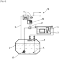
- the illustrated device 1 for maintaining the cold of a storage facility 2 for liquefied gas can ensure the maintenance of the cold and/or the maintenance of the pressure, for example, of a tank of liquefied natural gas, for example on a boat.
- This device 1 comprises a cryogenic refrigerator 3 and a sub-cooling circuit 4, 5 comprising a set of pipe(s).
- the subcooling circuit 4, 5 comprises at least one suction end 4 intended to be housed in a lower portion of a liquefied gas storage 2 and configured to suck in liquefied gas.
- the suction end 4 preferably comprises a suction pump 17.
- the subcooling circuit 4, 5 further comprises a heat exchanger 6 ensuring a heat exchange between the suction subcooling circuit 4, 5 and the refrigerator 3.
- this heat exchanger 6 is located outside the storage 2.
- the refrigerator may in particular comprise or consist of a cryogenic refrigerator or liquefier in which a cycle gas (helium, nitrogen, or other pure gas or mixture) undergoes a thermodynamic cycle (compression, cooling, expansion, reheating) producing a cold power at at least one end which can be transferred by heat exchange.
- a cycle gas helium, nitrogen, or other pure gas or mixture
- thermodynamic cycle compression, cooling, expansion, reheating
- the refrigerator is of the reverse Brayton cycle type and more particularly of the Turbo Brayton type using turbomachines (coupling on the same axis of at least one compressor and one turbine on bearings and magnetic motor).
- the subcooling circuit 4, 5 comprises at least one injection end 5, 7 configured to inject into the storage 2 the fluid cooled in the heat exchanger 6.
- the subcooling circuit 4, 5 comprises two injection ends 5, 7.
- a first end opens into the upper part of the storage in the form of nozzle(s) to allow the cooled fluid to be injected into the gas phase of storage 2 in order to recondense vapors
- a second end opens, for example, into the lower part of storage 2 to cool the liquid phase.
- the ejector at the bottom of storage 2 preferably returns the liquefied gas and the mixture to the liquid phase.
- the injected liquid is no longer subcooled but at the same temperature as the liquid in storage 2.
- the device 1 further comprises a pipe 8 for recovering vaporization gases having an upstream end connected to an upper portion of the storage 2 configured to recover vaporization gas.
- the recovery pipe 8 preferably comprises at least one member 11 for compressing the recovered vaporization gas (typically at least one compressor).
- the recovery line 8 comprises downstream at least one downstream end 18 intended to be connected to a consumer of the vaporization gas, for example a burner and/or an engine. This compression 11 makes it possible to maintain a constant pressure in the storage 2 and to supply gas to the engines, the excess combustible vaporization gas can be directed towards a combustion torch for example.
- the device 1 comprises a bypass line 9 and a set of valve(s) 10 configured to allow the transfer of vaporization gas from the recovery line 8 to the subcooling circuit 4, 5.
- This bypass line 9 has a first end connected to the recovery line 8, preferably downstream of the compression member 11, and a second downstream end connected to the subcooling circuit 4, 5, upstream of the heat exchanger 6.
- the set of valve(s) comprises a flow control valve 10 on the bypass line 9.
- This gas supplied by the bypass line 9 can be mixed within a flow of cryogenic liquid taken from the storage via the suction line 4 of the subcooling circuit.
- the gas taken and mixed with the liquid flow is preferably at a pressure at least higher than the discharge pressure of the liquid suction pump 17 located at the bottom of the cryogenic fluid storage 2.
- the device 1 may comprise a member 12 for mixing the vaporization gas in the subcooling circuit 4, 5.
- This mixing member 12 configured to achieve partial or total mixing of the gas in the liquid is located for example at the junction between the downstream end of the bypass pipe 9 and the subcooling circuit 4, 5.
- This mixing member 12 comprises for example at least one of: an indirect heat exchanger with injection, a gas injector in liquid, a static mixer, an upstream injector, a filtration system, a condenser pot with bulk or structured packing or any other suitable member or combination of several of these technologies.
- the flow control valve 10 is for example a piloted valve which can be configured to transfer a flow of vaporization gas to the subcooling circuit 4, 5 to increase the temperature of the fluid which enters the heat exchanger 6 by a determined value, for example between 5 and 25°C.
- the flow control valve 10 may be configured to transfer a flow of vaporization gas to the subcooling circuit 4, 5 to maintain the temperature of the fluid entering the heat exchanger 6 below the saturation temperature of the liquefied gas. This allows the mixture to remain in the liquid phase. It is possible to provide a temperature margin, for example 2°C below saturation, in order to ensure that no gas bubbles enter the heat exchanger 6.
- the regulation of the flow rate of mixed gas upstream of the heat exchanger 6 can be carried out for example by calculating a saturation temperature of the fluid (the bubble point temperature being the temperature at which the first vapor bubble is created).
- This saturation temperature can be based on a typical composition of the stored fluid.
- This saturation temperature can possibly be adjusted according to a correlation via a pressure parameter for example. It is thus possible to control the injection of vaporization gas by the flow control valve 10 until obtaining as outlet temperature of the mixer 10 a temperature with a safety deviation from the saturation temperature (temperature at the outlet of mixer 12 being equal to the saturation temperature of the fluid minus the safety margin).
- the flow control valve 10 can be controlled to maintain the temperature of the fluid leaving the heat exchanger 6 above a determined value, for example above -160°C and/or at a value equal to the temperature of the liquefied gas in the storage and/or at a value equal to the temperature of the liquefied gas sucked into the suction end 4.
- the flow rate can be adjusted by the flow control valve 10 so that the temperature of the fluid at the outlet of the cooling exchanger 6 is equal to the temperature of the liquid in the storage 2.
- This dissolution of the vaporization gas in the liquid is done by raising the temperature of the cryogenic liquid.
- the quantity of gas injected via the bypass line 9 can therefore allow the choice of adjusting a temperature at the inlet and/or outlet of the refrigerator (at the inlet and/or outlet of the heat exchanger 6).
- This control can be carried out by a simple regulating valve 10 flow rate.
- the temperature of the fluid to be cooled can therefore be measured at the inlet and/or outlet of the heat exchanger 6 by one or more appropriate temperature sensors 19.
- Refrigerator 3 reduces the temperature of the liquid or gas/liquid mixture obtained before returning it to storage 2 (at the bottom of the storage and/or in the upper part via one or more ramps or nozzle(s)).
- the temperature of the fluid leaving the cooling heat exchanger 6 is thus controlled such that it does not generate any solidification or less solidification within the heat exchanger 6. This temperature is therefore at least equal to the initial temperature of the cryogenic liquid pumped into the storage 2.
- the quantity of gas injected via the bypass pipe 9 can also make it possible to regulate the pressure drop within the heat exchanger 6.
- the device 1 can also be used in "mixed" mode, that is to say by combining on the one hand, a liquefaction of the recovered and compressed and reinjected vaporization gas and, on the other hand, a partial sub-cooling of the cryogenic liquid before returning to the storage 2.
- the device 1 can alternatively operate in subcooling mode in which the injection of relatively warmer vaporization gas is stopped via the bypass line 9 (valve 10 closed) or in liquefaction mode by injection of vaporization gas via the bypass line 9 (valve 10 open).
- the switch from one mode to the other can be decided for example arbitrarily by an operator according to the risk of blockage of the heat exchanger 6 and/or automatically via a detection or forecast (intelligence) detecting the occurrence of a blockage (increase in the pressure difference at the terminals of the heat exchanger 6, drop in temperatures, etc.).
- the method of realization of the [ Fig. 2 ] is distinguished from that of the [ Fig. 1 ] in that the bypass line 9 comprises a pre-cooling member 13 in heat exchange with the vaporization gas transferred to the sub-cooling circuit 4, 5.
- This pre-cooling member 13 can be configured for example to cool the flow of vaporization gas transferred to an intermediate temperature between the temperature of the vaporization gas of the recovery line 8 and the temperature of the liquefied gas pumped into the storage 2.
- this pre-cooling member 13 may comprise or consist of at least one of: a refrigeration cycle using a refrigerant fluid, a compression system and an expansion system of the valve, orifice or turbine type.
- the method of realization of the [ Fig. 3 ] is distinguished from that of the [ Fig. 1 ] in that the recovery line 8 comprises a heat exchanger 16 allowing a heat exchange between the vaporization gas of the recovery line 8 and the vaporization gas of the bypass line 9.
- the bypass line 9 comprises a divert line 14 and set of valve(s) 15 allowing the flow of vaporization gas from the bypass line 9 to be controlled to circulate in the heat exchanger 16 of the recovery line 8. This allows the vaporization gas to be pre-cooled by recovering cold power from the vaporization gas taken from the storage 2, upstream of the compression.
- One or more control valves can allow the temperature of the gas entering the compression member, the temperature of the fluid entering the refrigerator (entering the heat exchanger 6) or the temperature of the fluid leaving the heat exchanger 6 to be controlled as desired. This control can be carried out to maximize the recovered cold power while ensuring proper operation of the compression 11 and preventing the formation of solids in the heat exchanger 6 of the refrigerator 3. This makes it possible to optimize/increase the quantity of compressed vaporization gas injectable via the bypass line 9.
- the method of realization of the [ Fig. 4 ] is distinguished from that of the [ Fig. 1 ] in that the recovery line 8 comprises several compressors 11 in series and the first upstream end of the bypass line 9 is connected to the recovery line 8 downstream of an intermediate compressor 11, that is to say upstream of the last compressor in series.
- the vaporization gas is recovered at the outlet of the first or a subsequent compression stage rather than at the outlet of the last compressor.
- the pressure of the recovered gas is, however, preferably higher than the pressure of the liquid pumped into the storage with which it is mixed.
- the temperature of this vaporization gas at an intermediate compression stage is relatively colder than at the outlet of the last compressor.
- the quantity of vaporization gas that can be mixed with the liquid may thus be greater than in the embodiment of the [ Fig. 1 ].
- This embodiment can further replace the pre-cooling member 13 of the embodiment of the [ Fig. 2 ].
- the device thus allows optimal management of vaporization gases and cold maintenance (subcooling in particular) of a liquefied gas storage, for example methane, without generating a solid deposit in the cooling heat exchanger 6.
- the invention makes it possible to avoid or limit a degradation in the performance of the device.
- the vaporization gas injected upstream of the heat exchanger 6 of the refrigerator 3 heats the liquid before it cools.
- the refrigerator 3 then brings this mixture back to, for example, the temperature of the fluid in the storage 2.
- the vaporization gas taken 9 and mixed is totally or partially liquefied on its return to storage 2.
- the coldest temperature reached by the fluid in the heat exchanger 6 does not allow solidification conditions to be reached.
- the solution described allows to convert by adaptation a classic subcooling system into a direct reliquefier in the event of the presence of pollutants such as heavy hydrocarbons.
- the solution prevents the phenomena of crystallization of heavy hydrocarbons during cooling.
Landscapes
- Engineering & Computer Science (AREA)
- Mechanical Engineering (AREA)
- General Engineering & Computer Science (AREA)
- Physics & Mathematics (AREA)
- Thermal Sciences (AREA)
- Chemical & Material Sciences (AREA)
- Ocean & Marine Engineering (AREA)
- Combustion & Propulsion (AREA)
- Chemical Kinetics & Catalysis (AREA)
- General Chemical & Material Sciences (AREA)
- Oil, Petroleum & Natural Gas (AREA)
- Filling Or Discharging Of Gas Storage Vessels (AREA)
- Separation By Low-Temperature Treatments (AREA)
Abstract
Description
- L'invention concerne un dispositif, une installation et un procédé de maintien en froid d'un stockage de gaz liquéfié.
- L'invention concerne en particulier un dispositif et un procédé de maintien en froid et/ou de maintien en pression d'un stockage de gaz liquéfié, par exemple du gaz naturel liquéfié.
- L'invention concerne plus particulièrement un dispositif de maintien en froid d'un stockage de gaz liquéfié, par exemple du gaz naturel liquéfié, comprenant un réfrigérateur cryogénique, un circuit de sous-refroidissement comprenant un ensemble de conduite(s), le circuit de sous-refroidissement comprenant une extrémité d'aspiration destinée à être logée dans une portion inférieure d'un stockage de gaz liquéfié configurée pour aspirer du gaz liquéfié, un échangeur de chaleur assurant un échange thermique entre le circuit de sous-refroidissement aspiré et le réfrigérateur, le circuit de sous-refroidissement comprenant au moins une extrémité d'injection configurée pour injecter dans le stockage le fluide refroidi dans l'échangeur de chaleur, le dispositif comprenant en outre une conduite de récupération des gaz de vaporisation ayant une extrémité amont destinée à être reliée à une portion supérieure du stockage pour récupérer du gaz de vaporisation, la conduite de récupération comprenant une extrémité aval destinée à être reliée à un consommateur du gaz de vaporisation, par exemple un brûleur et/ou un moteur, le dispositif comprenant une conduite de dérivation et un ensemble de vanne(s) configurés pour permettre le transfert de gaz de vaporisation de la conduite de récupération vers le circuit de sous-refroidissement, la conduite de dérivation ayant une première extrémité reliée à la conduite de récupération et une seconde extrémité reliée au circuit de sous-refroidissement.
- Les gaz de vaporisation d'un fluide cryogénique dans un stockage peuvent être récupérées par reliquéfaction directe. La solution consiste en une compression cryogénique de ces évaporations, mise à température ambiante puis envoi vers un liquéfacteur.
- Une autre fonctionnalité consiste en la reliquéfaction des gaz d'évaporation effectuée grâce au transfert de puissance froide d'un réfrigérateur vers le liquide cryogénique par sous-refroidissement de celui-ci, qui est ensuite renvoyé dans le stockage.
- Le document
WO2019020742 A1 décrit une installation assurant le traitement de gaz de vaporisation ou le refroidissement du gaz liquéfié. - L'échangeur de refroidissement peut être sujet à un encrassement dû à la précipitation des composants les plus lourds (plus on refroidit, moins il y a de solubilité). En effet, le fluide cryogénique n'est pas nécessairement un composé pur et peut être sous-forme de mélange. Ainsi certains des composants du mélange peuvent être solidifiés au cours du sous-refroidissement. Ces particules solides peuvent encrasser l'échangeur du réfrigérateur et ainsi dégrader les performances du système.
- Diverses solutions sont connues pour résorber ou limiter cet encrassement. Cependant ces solutions ne sont pas satisfaisantes pour à la fois traiter les gaz de vaporisation et/ou de sousrefroidir un gaz liquéfié stocké.
- Un but de la présente invention est de pallier tout ou partie des inconvénients de l'art antérieur relevés ci-dessus.
- A cette fin, le dispositif selon l'invention, par ailleurs conforme à la définition générique qu'en donne le préambule ci-dessus, est essentiellement caractérisé en ce que la seconde extrémité de la conduite de dérivation est reliée au circuit de sous-refroidissement en amont de l'échangeur de chaleur.
- Par ailleurs, des modes de réalisation de l'invention peuvent comporter l'une ou plusieurs des caractéristiques suivantes :
- l'ensemble de vanne(s) comprend une vanne de régulation de débit sur la conduite de dérivation,
- la vanne de régulation de débit est une vanne pilotée configurée pour transférer un débit de gaz de vaporisation vers le circuit de sous-refroidissement pour augmenter la température du fluide qui entre dans l'échangeur de chaleur d'une valeur déterminée, par exemple entre 5 et 25°C,
- la vanne de régulation de débit est une vanne pilotée configurée pour transférer un débit de gaz de vaporisation vers le circuit de sous-refroidissement pour maintenir la température du fluide qui entre dans l'échangeur de chaleur en-dessous de la température de saturation du gaz liquéfié,
- la vanne de régulation de débit est une vanne pilotée configurée pour transférer un débit de gaz de vaporisation vers le circuit de sous-refroidissement pour maintenir la température du fluide qui sort de l'échangeur de chaleur au-dessus d'une valeur déterminée, par exemple au-dessus de -160°C et/ou à une valeur égale à la température du gaz liquéfié dans le stockage et/ou à une valeur égale à la température du gaz liquéfié aspiré dans l'extrémité d'aspiration,
- la conduite de récupération comprenant au moins un compresseur, la première extrémité de la conduite de dérivation est reliée à la conduite de récupération en aval du compresseur,
- la conduite de récupération comprend plusieurs compresseurs en série, la première extrémité de la conduite de dérivation est reliée à la conduite de récupération en aval d'un compresseur intermédiaire, c'est-à-dire en amont du dernier compresseur en série,
- le compresseur est configuré pour fournir un flux de gaz à la conduite de dérivation ayant une pression supérieure à la pression du liquide aspiré au niveau de l'extrémité d'aspiration et fourni au circuit de sous-refroidissement,
- le dispositif comporte un organe de mélange du gaz de vaporisation dans le circuit de sous-refroidissement, l'organe de mélange étant situé par exemple au niveau de la jonction entre la seconde extrémité de la conduite de dérivation et le circuit de sous-refroidissement, l'organe de mélange comprenant au moins l'un parmi : un échangeur de chaleur indirect avec injection, un injecteur de gaz dans du liquide, un mélangeur statique, un injecteur en amont, un système de filtration, un pot condenseur avec garnissage de type vrac ou structuré,
- la conduite de dérivation comprend un organe de pré-refroidissement en échange thermique avec le gaz de vaporisation transféré vers le circuit de sous-refroidissement, l'organe de pré-refroidissement étant configuré par exemple pour refroidir le flux le gaz de vaporisation transféré à une température intermédiaire entre la température du gaz de vaporisation de la conduite de récupération et la température du gaz liquéfié,
- la conduite de récupération comprend un échangeur de chaleur permettant un échange thermique entre le gaz de vaporisation de la conduite de récupération et du gaz de vaporisation de la conduite de dérivation,
- la conduite de dérivation comprend une conduite de détour et ensemble de vanne(s) permettant de contrôler le flux de gaz de vaporisation de la conduite de dérivation admis à circuler dans l'échangeur de chaleur de la conduite de récupération,
- l'extrémité d'aspiration comprend une pompe d'aspiration.
- L'invention concerne également une installation de stockage de gaz liquéfié, par exemple du gaz naturel liquéfié, par exemple bateau, de transport de gaz liquéfié, comprenant au moins un stockage de gaz liquéfié et un dispositif de maintien en froid du fluide contenu dans le stockage, le dispositif de maintien en froid étant conforme à l'une quelconque des caractéristiques précédentes ou ci-dessous.
- L'invention concerne également un procédé de maintien en froid d'un stockage de gaz liquéfié utilisant un dispositif selon l'une quelconque des revendications précédentes comprenant un pompage de gaz liquéfié dans un stockage cryogénique, un refroidissement du gaz liquéfié pompé et une réinjection du gaz liquéfié refroidi dans le stockage, le procédé comprenant une récupération de gaz de vaporisation du stockage et une étape d'injection et de mélange de gaz de vaporisation dans le gaz liquéfié pompé avant son refroidissement.
- Ceci permet d'augmenter la température du fluide en entrée du circuit de sous-refroidissement par injection de gaz de vaporisation afin de permettre de pas cristalliser d'hydrocarbures lourds dans l'échangeur 6 de chaleur puisque le sous-refroidisseur (réfrigérateur) est de préférence configuré pour ne jamais descendre la température du fluide à refroidir plus bas que la température initiale du liquide sous-refroidi.
- Selon d'autres particularités possibles, l'étape d'injection et de mélange est configurée pour remonter la température du gaz liquéfié pompé avant refroidissement d'une valeur déterminée et/ou pour maintenir la température du gaz liquéfié refroidi en-dessous d'un seuil déterminé et/ou au niveau de la température du gaz liquéfié dans le stockage ou pompé.
- L'invention peut concerner également tout dispositif ou procédé alternatif comprenant toute combinaison des caractéristiques ci-dessus ou ci-dessous dans le cadre des revendications. D'autres particularités et avantages apparaîtront à la lecture de la description ci-après, faite en référence aux figures dans lesquelles :
- L'invention sera mieux comprise à la lecture de la description qui va suivre donnée uniquement à titre d'exemple et faite en se référant aux dessins annexés dans lesquels :
- [
Fig. 1 ] est une vue schématique illustrant un exemple de structure et de fonctionnement d'une installation selon un premier mode de réalisation de l'invention, - [
Fig. 2 ] est une vue schématique illustrant un exemple de structure et de fonctionnement d'une installation selon un deuxième mode de réalisation de l'invention, - [
Fig. 3 ] est une vue schématique illustrant un exemple de structure et de fonctionnement d'une installation selon un troisième mode de réalisation de l'invention, - [
Fig. 4 ] est une vue schématique illustrant un exemple de structure et de fonctionnement d'une installation selon un quatrième mode de réalisation de l'invention. - Sur toutes les figures, les mêmes références se rapportent aux mêmes éléments.
- Dans cette description détaillée, les réalisations suivantes sont des exemples. Bien que la description se réfère à un ou plusieurs modes de réalisation, cela ne signifie pas que les caractéristiques s'appliquent seulement à un seul mode de réalisation. De simples caractéristiques de différents modes de réalisation peuvent également être combinées et/ou interchangées pour fournir d'autres réalisations.
- Le dispositif 1 de maintien en froid d'un stockage 2 de gaz liquéfié illustré peut assurer le maintien en froid et/ou le maintien en pression par exemple d'un réservoir de gaz naturel liquéfié, par exemple sur un bateau.
- Ce dispositif 1 comprend un réfrigérateur 3 cryogénique et un circuit 4, 5 de sous-refroidissement comprenant un ensemble de conduite(s).
- Le circuit 4, 5 de sous-refroidissement comprend au moins une extrémité 4 d'aspiration destinée logée dans une portion inférieure d'un stockage 2 de gaz liquéfié et configurée pour aspirer du gaz liquéfié. Comme illustré, l'extrémité 4 d'aspiration comprend de préférence une pompe 17 d'aspiration.
- Le circuit 4, 5 de sous-refroidissement comprend en outre un échangeur 6 de chaleur assurant un échange thermique entre le circuit 4, 5 de sous-refroidissement aspiré et le réfrigérateur 3. De préférence, cet échangeur 6 de chaleur est situé en dehors du stockage 2.
- Le réfrigérateur peut en particulier comprendre ou être constitué d'un réfrigérateur ou liquéfacteur cryogénique dans lequel un gaz de cycle (hélium, azote, ou autre gaz pur ou mélange) subit un cycle thermodynamique (compression, refroidissement, détente, réchauffage) produisant une puissance froide à au moins une extrémité qui peut être transféré par échange thermique. Par exemple le réfrigérateur est du type à cycle Brayton inverse et plus particulièrement de type Turbo Brayton mettant en oeuvre des turbomachines (attelage sur un même axe d'au moins un compresseur et une turbine sur paliers et moteur magnétique). Le circuit 4, 5 de sous-refroidissement comprend au moins une extrémité 5, 7 d'injection configurée pour injecter dans le stockage 2 le fluide refroidi dans l'échangeur 6 de chaleur. Dans l'exemple illustré, le circuit 4, 5 de sous-refroidissement comprend deux extrémités 5, 7 d'injection. Une première extrémité débouche en partie supérieure du stockage sous forme de buse(s) pour permettre d'injecter le fluide refroidi dans la phase gazeuse du stockage 2 en vue de recondenser des vapeurs et/ contrôler la pression dans le stockage 2.
- Une deuxième extrémité débouche par exemple en partie inférieure du stockage 2 pour refroidir la phase liquide.
- Selon l'invention l'éjecteur en fond de stockage 2 (injecteur) renvoie de préférence le gaz liquéfié et le mélange à la phase liquide. Le liquide injecté n'est plus sous-refroidi mais à la même température que le liquide dans le stockage 2.
- Le dispositif 1 comprend en outre une conduite 8 de récupération des gaz de vaporisation ayant une extrémité amont reliée à une portion supérieure du stockage 2 configurée pour récupérer du gaz de vaporisation. La conduite 8 de récupération comprend de préférence au moins un organe 11 de compression du gaz de vaporisation récupéré (typiquement au moins un compresseur). La conduite 8 de récupération comprend en aval au moins une extrémité aval 18 destinée à être reliée à un consommateur du gaz de vaporisation, par exemple un brûleur et/ou un moteur. Cette compression 11 permet de maintenir une pression constante dans le stockage 2 et d'alimenter en gaz des moteurs, l'excès de gaz de vaporisation combustible peut être dirigé vers une torche de combustion par exemple.
- Le dispositif 1 comprend une conduite 9 de dérivation et un ensemble de vanne(s) 10 configurés pour permettre le transfert de gaz de vaporisation de la conduite 8 de récupération vers le circuit 4, 5 de sous-refroidissement. Cette conduite 9 de dérivation possède une première extrémité reliée à la conduite 8 de récupération, de préférence en aval de l'organe 11 de compression, et une seconde extrémité aval reliée au circuit 4, 5 de sous-refroidissement, en amont de l'échangeur 6 de chaleur. Par exemple, l'ensemble de vanne(s) comprend une vanne 10 de régulation de débit sur la conduite 9 de dérivation.
- Ceci permet de prévenir les phénomènes d'encrassement par injection de gaz de vaporisation prélevé, par exemple en sortie de la compression, par exemple à température ambiante.
- Ceci permet d'injecter du gaz relativement plus chaud en amont du refroidissement par le réfrigérateur/liquéfacteur. Ce gaz apporté par la conduite 9 de dérivation peut être mélangé au sein d'un flux de liquide cryogénique prélevé dans le stockage via la conduite 4 d'aspiration du circuit de sous-refroidissement.
- Le gaz prélevé et mélangé au flux de liquide est de préférence à une pression au moins supérieure à la pression de refoulement de la pompe 17 d'aspiration de liquide située au fond du stockage 2 du fluide cryogénique.
- Comme illustré, le dispositif 1 peut comporter un organe 12 de mélange du gaz de vaporisation dans le circuit 4, 5 de sous-refroidissement. Cet organe 12 de mélange configuré pour réaliser un mélange partiel ou total du gaz dans le liquide est situé par exemple au niveau de la jonction entre l'extrémité aval de la conduite 9 de dérivation et le circuit 4, 5 de sous-refroidissement. Cet organe 12 de mélange comprend par exemple au moins l'un parmi : un échangeur de chaleur indirect avec injection, un injecteur de gaz dans du liquide, un mélangeur statique, un injecteur en amont, un système de filtration, un pot condenseur avec garnissage de type vrac ou structuré ou tout autre organe approprié ou combinaison de plusieurs de ces technologies.
- La vanne 10 de régulation de débit est par exemple une vanne pilotée qui peut être configurée pour transférer un débit de gaz de vaporisation vers le circuit 4, 5 de sous-refroidissement pour augmenter la température du fluide qui entre dans l'échangeur 6 de chaleur d'une valeur déterminée, par exemple entre 5 et 25°C.
- Par exemple, la vanne 10 de régulation de débit peut être configurée pour transférer un débit de gaz de vaporisation vers le circuit 4, 5 de sous-refroidissement pour maintenir la température du fluide qui entre dans l'échangeur 6 de chaleur en-dessous de la température de saturation du gaz liquéfié. Ceci permet au mélange de rester en phase liquide. Il est possible de prévoir une marge de température, par exemple 2°C sous la saturation, afin de garantir qu'aucune bulle de gaz n'entre dans l'échangeur 6 de chaleur.
- La régulation du débit de gaz mélangé en amont de l'échangeur 6 de chaleur peut être réalisée par exemple en calculant une température de saturation du fluide (la température du point de bulle étant la température à laquelle il y a création de la première bulle de vapeur).
- Cette température de saturation peut être basée sur une composition type du fluide stocké.
- Cette température de saturation peut éventuellement être ajustée selon une corrélation via un paramètre de pression par exemple. Il est ainsi possible de contrôler l'injection de gaz de vaporisation par la vanne 10 de régulation de débit jusqu'à obtenir comme température de sortie du mélangeur 10 une température avec un écart de sécurité par rapport à la température de saturation (température en sortie de mélangeur 12 étant égale à la température de saturation du fluide moins la marge de sécurité).
- Alternativement ou en combinaison, la vanne 10 de régulation de débit peut être pilotée pour maintenir la température du fluide qui sort de l'échangeur 6 de chaleur au-dessus d'une valeur déterminée, par exemple au-dessus de -160°C et/ou à une valeur égale à la température du gaz liquéfié dans le stockage et/ou à une valeur égale à la température du gaz liquéfié aspiré dans l'extrémité 4 d'aspiration.
- Par exemple, il est possible de mesurer la température du fluide en sortie de pompe 17 et/ou dans le stockage 2. Le débit peut être ajusté par la vanne 10 de régulation de débit pour que la température du fluide en sortie de l'échangeur 6 de refroidissement soit égale à la température du liquide dans le stockage 2.
- L'augmentation de pression du liquide pompé permet d'élever son point de saturation. Cela a pour conséquence de permettre une solubilité totale ou partielle du gaz dans le liquide cryogénique en amont du liquéfacteur.
- Cette dissolution du gaz de vaporisation dans le liquide se fait par élévation de température du liquide cryogénique.
- La quantité de gaz injecté via la conduite 9 de dérivation peut donc permettre au choix de régler une température en entrée et/ou en sortie du réfrigérateur (en entrée et/ou en sortie de l'échangeur 6 de chaleur). Ce contrôle peut être opéré par une simple vanne 10 de régulation de débit. La température du fluide à refroidir peut donc être mesurée en entrée et/ou en sortie de l'échangeur 6 de chaleur par un ou des capteurs 19 de température appropriés.
- Le réfrigérateur 3 diminue la température du liquide ou du mélange gaz/liquide obtenu avant de le renvoyer dans le stockage 2 (en fond de stockage et/ou en partie supérieure via une ou des rampes ou buse(s)).
- La température du fluide en sortie de l'échangeur 6 de chaleur de refroidissement est ainsi contrôlée telle qu'elle ne génère pas ou moins de solidification au sein de l'échangeur 6 de chaleur. Cette température est donc au moins égale à la température initiale du liquide cryogénique pompé dans le stockage 2. La quantité de gaz injecté via la conduite 9 de dérivation peut également permettre de réguler la perte de charge au sein de l'échangeur 6 de chaleur. Le dispositif 1 peut également être utilisé en mode "mixte", c'est-à-dire en combinant d'une part, une liquéfaction du gaz de vaporisation récupéré et comprimé et réinjecté et, d'autre part, un sous-refroidissement partiel du liquide cryogénique avant retour vers le stockage 2.
- Le dispositif 1 peut alternativement fonctionner en mode de sous-refroidissement dans lequel on arrête l'injection de gaz de vaporisation relativement plus chaud via la conduite 9 de dérivation (vanne 10 fermée) ou en mode de liquéfaction par injection de gaz de vaporisation via la conduite 9 de dérivation (vanne 10 ouverte).
- Ceci permet un système flexible proposant les deux modes de fonctionnement. La bascule d'un mode à l'autre peut être décidée par exemple arbitrairement par un opérateur selon le risque de bouchage de l'échangeur 6 de chaleur et/ou automatiquement via une détection ou prévision (intelligence) détectant l'occurrence d'un bouchage (augmentation de la différence de pression au bornes de l'échangeur 6 de chaleur, baisse des températures,...).
- Le mode de réalisation de la [
Fig. 2 ] se distingue de celui de la [Fig. 1 ] en ce que la conduite 9 de dérivation comprend un organe 13 de pré-refroidissement en échange thermique avec le gaz de vaporisation transféré vers le circuit 4, 5 de sous-refroidissement. Cet organe 13 de pré-refroidissement peut être configuré par exemple pour refroidir le flux le gaz de vaporisation transféré à une température intermédiaire entre la température du gaz de vaporisation de la conduite 8 de récupération et la température du gaz liquéfié pompé dans le stockage 2. - Ceci permet d'optimiser ou augmenter la quantité de gaz comprimé injectable via le pré-refroidissement 13 externe ayant une température intermédiaire entre la température du liquide cryogénique et la température ambiante. Par exemple, cet organe 13 de pré-refroidissement peut comprendre ou être constitué de l'un au moins parmi: un cycle de réfrigération utilisant un fluide réfrigérant, un système de compression et un système de détente de type vanne, orifice ou turbine.
- Le mode de réalisation de la [
Fig. 3 ] se distingue de celui de la [Fig. 1 ] en ce que la conduite 8 de récupération comprend un échangeur 16 de chaleur permettant un échange thermique entre le gaz de vaporisation de la conduite 8 de récupération et du gaz de vaporisation de la conduite 9 de dérivation. Par exemple, la conduite 9 de dérivation comprend une conduite 14 de détour et ensemble de vanne(s) 15 permettant de contrôler le flux de gaz de vaporisation de la conduite 9 de dérivation admis à circuler dans l'échangeur 16 de chaleur de la conduite 8 de récupération. Ceci permet de réaliser un pré-refroidissement du gaz de vaporisation en récupérant de la puissance froide sur le gaz de vaporisation prélevé du stockage 2, en amont de la compression. Une ou des vannes de régulation peuvent permettre de contrôler au choix la température du gaz en entrée de l'organe de compression, la température du fluide en entrée du réfrigérateur (en entrée de l'échangeur 6 de chaleur) ou la température du fluide à la sortie de l'échangeur 6 de chaleur. Ce contrôle peut être réalisé pour maximiser la puissance froide récupérée tout en garantissant un bon fonctionnement de la compression 11 et en empêchant la formation de solide dans l'échangeur 6 de chaleur du réfrigérateur 3. Ceci permet d'optimiser/augmenter la quantité de gaz de vaporisation comprimé injectable via la conduite 9 de dérivation. - Le mode de réalisation de la [
Fig. 4 ] se distingue de celui de la [Fig. 1 ] en ce que la conduite 8 de récupération comprend plusieurs compresseurs 11 en série et la première extrémité amont de la conduite 9 de dérivation est reliée à la conduite 8 de récupération en aval d'un compresseur 11 intermédiaire, c'est-à-dire en amont du dernier compresseur en série. - C'est-à-dire que le gaz de vaporisation est récupéré en sortie du premier ou d'un étage de compression ultérieur plutôt qu'à la sortie du dernier compresseur. La pression du gaz récupéré est cependant de préférence supérieure à la pression du liquide pompé dans le stockage auquel il est mélangé. La température de ce gaz de vaporisation à un stade de compression intermédiaire est relativement plus froide qu'à la sortie du dernier compresseur. La quantité de gaz de vaporisation pouvant être mélangé au liquide pourra ainsi être plus importante que dans le mode de réalisation de la [
Fig. 1 ]. Ce mode de réalisation peut en outre remplacer l'organe 13 de pré-refroidissement du mode de réalisation de la [Fig. 2 ]. - Le dispositif permet ainsi une gestion optimale des gaz de vaporisation et de maintien en froid (sous-refroidissement notamment) d'un stockage de gaz liquéfié, par exemple du méthane sans générer un dépôt solide dans l'échangeur 6 de chaleur de refroidissement. L'invention permet d'éviter ou de limiter une dégradation de la performance du dispositif
- Le gaz de vaporisation injecté en amont de l'échangeur 6 de chaleur du réfrigérateur 3 réchauffe le liquide avant son refroidissement. Le réfrigérateur 3 ramène ensuite ce mélange par exemple la température du fluide dans le stockage 2.
- Le gaz de vaporisation prélevé 9 et mélangé est totalement ou partiellement liquéfié à son retour dans le stockage 2. La température la plus froide atteinte par le fluide dans l'échangeur 6 de chaleur ne permet pas d'atteindre les conditions de solidification.
- La solution décrite permet de convertir par adaptation un système de sous-refroidissement classique en reliquéfacteur direct en cas de présence de polluants type hydrocarbures lourds. La solution permet d'empêcher les phénomènes de cristallisation des hydrocarbures lourds lors du refroidissement.
Claims (16)
- Dispositif de maintien en froid d'un stockage (2) de gaz liquéfié, par exemple du gaz naturel liquéfié, comprenant un réfrigérateur (3) cryogénique, un circuit (4, 5) de sous-refroidissement comprenant un ensemble de conduite(s), le circuit (4, 5) de sous-refroidissement comprenant une extrémité (4) d'aspiration destinée à être logée dans une portion inférieure d'un stockage (2) de gaz liquéfié configurée pour aspirer du gaz liquéfié, un échangeur (6) de chaleur assurant un échange thermique entre le fluide aspiré par le circuit (4, 5) de sous-refroidissement et le réfrigérateur (3), le circuit (4, 5) de sous-refroidissement comprenant au moins une extrémité (5, 7) d'injection configurée pour injecter dans le stockage (2) le fluide refroidi dans l'échangeur (6) de chaleur, le dispositif (1) comprenant en outre une conduite (8) de récupération des gaz de vaporisation ayant une extrémité amont destinée à être reliée à une portion supérieure du stockage (2) pour récupérer du gaz de vaporisation, la conduite (8) de récupération comprenant une extrémité aval (18) destinée à être reliée à un consommateur du gaz de vaporisation, par exemple un brûleur et/ou un moteur, le dispositif (1) comprenant une conduite (9) de dérivation et un ensemble de vanne(s) (10) configurés pour permettre le transfert de gaz de vaporisation de la conduite (8) de récupération vers le circuit (4, 5) de sous-refroidissement, la conduite (9) de dérivation ayant une première extrémité reliée à la conduite (8) de récupération et une seconde extrémité reliée au circuit (4, 5) de sous-refroidissement, caractérisé en ce que la seconde extrémité de la conduite (9) de dérivation est reliée au circuit (4, 5) de sous-refroidissement en amont de l'échangeur (6) de chaleur.
- Dispositif selon la revendication 1, caractérisé en ce que l'ensemble de vanne(s) (10) comprend une vanne de régulation de débit sur la conduite (9) de dérivation.
- Dispositif selon la revendication 2, caractérisé en ce que la vanne (10) de régulation de débit est une vanne pilotée configurée pour transférer un débit de gaz de vaporisation vers le circuit (4, 5) de sous-refroidissement pour augmenter la température du fluide qui entre dans l'échangeur (6) de chaleur d'une valeur déterminée, par exemple entre 5 et 25°C.
- Dispositif selon la revendication 2 ou 3, caractérisé en ce que la vanne (10) de régulation de débit est une vanne pilotée configurée pour transférer un débit de gaz de vaporisation vers le circuit (4, 5) de sous-refroidissement pour maintenir la température du fluide qui entre dans l'échangeur (6) de chaleur en-dessous de la température de saturation du gaz liquéfié.
- Dispositif selon l'une quelconque des revendications 2 à 4, caractérisé en ce que la vanne (10) de régulation de débit est une vanne pilotée configurée pour transférer un débit de gaz de vaporisation vers le circuit (4, 5) de sous-refroidissement pour maintenir la température du fluide qui sort de l'échangeur (6) de chaleur au-dessus d'une valeur déterminée, par exemple au-dessus de -160°C et/ou à une valeur égale à la température du gaz liquéfié dans le stockage et/ou à une valeur égale à la température du gaz liquéfié aspiré dans l'extrémité (4) d'aspiration.
- Dispositif selon l'une quelconque des revendications 1 à 5, caractérisé en ce que la conduite (8) de récupération comprenant au moins un compresseur (11) et en ce que la première extrémité de la conduite (9) de dérivation est reliée à la conduite (8) de récupération en aval du compresseur (11).
- Dispositif selon la revendication 6, caractérisé en ce que la conduite (8) de récupération comprend plusieurs compresseurs (11) en série et en ce que la première extrémité de la conduite (9) de dérivation est reliée à la conduite (8) de récupération en aval d'un compresseur (11) intermédiaire, c'est-à-dire en amont du dernier compresseur en série.
- Dispositif selon la revendication 6 ou 7, caractérisé en ce que le compresseur (11) est configuré pour fournir un flux de gaz à la conduite (9) de dérivation ayant une pression supérieure à la pression du liquide aspiré au niveau de l'extrémité (4) d'aspiration et délivré au circuit (4, 5) de sous-refroidissement.
- Dispositif selon l'une quelconque des revendications 1 à 8, caractérisé en ce qu'il comporte un organe (12) de mélange du gaz de vaporisation dans le circuit (4, 5) de sous-refroidissement, l'organe (12) de mélange étant situé par exemple au niveau de la jonction entre la seconde extrémité de la conduite (9) de dérivation et le circuit (4, 5) de sous-refroidissement, l'organe (12) de mélange comprenant au moins l'un parmi : un échangeur de chaleur indirect avec injection, un injecteur de gaz dans du liquide, un mélangeur statique, un injecteur en amont, un système de filtration, un pot condenseur avec garnissage de type vrac ou structuré.
- Dispositif selon l'une quelconque des revendications 1 à 9, caractérisé en ce que la conduite (9) de dérivation comprend un organe (13) de pré-refroidissement en échange thermique avec le gaz de vaporisation transféré vers le circuit (4, 5) de sous-refroidissement, l'organe (13) de pré-refroidissement étant configuré par exemple pour refroidir le flux le gaz de vaporisation transféré à une température intermédiaire entre la température du gaz de vaporisation de la conduite (8) de récupération et la température du gaz liquéfié.
- Dispositif selon l'une quelconque des revendications 1 à 10, caractérisé en ce que la conduite (8) de récupération comprend un échangeur (16) de chaleur permettant un échange thermique entre le gaz de vaporisation de la conduite (8) de récupération et du gaz de vaporisation de la conduite (9) de dérivation.
- Dispositif selon la revendication 11, caractérisé en ce que la conduite (9) de dérivation comprend une conduite (14) de détour et ensemble de vanne(s) (15) permettant de contrôler le flux de gaz de vaporisation de la conduite (9) de dérivation admis à circuler dans l'échangeur (16) de chaleur de la conduite (8) de récupération.
- Dispositif selon l'une quelconque des revendications 1 à 12, caractérisé en ce que l'extrémité (4) d'aspiration comprend une pompe (17) d'aspiration.
- Installation de stockage de gaz liquéfié, par exemple du gaz naturel liquéfié, par exemple bateau, de transport de gaz liquéfié, comprenant au moins un stockage (2) de gaz liquéfié et un dispositif de maintien en froid du fluide contenu dans le stockage, le dispositif (1) de maintien en froid étant conforme à l'une quelconque des revendications précédentes.
- Procédé de maintien en froid d'un stockage (2) de gaz liquéfié utilisant un dispositif selon l'une quelconque des revendications 1 à 13 comprenant un pompage de gaz liquéfié dans un stockage cryogénique, un refroidissement du gaz liquéfié pompé et une réinjection du gaz liquéfié refroidi dans le stockage, le procédé comprenant une récupération de gaz de vaporisation du stockage et une étape d'injection et de mélange de gaz de vaporisation dans le gaz liquéfié pompé avant son refroidissement.
- Procédé selon la revendication 15, caractérisé en ce que l'étape d'injection et de mélange est configurée pour remonter la température du gaz liquéfié pompé avant refroidissement d'une valeur déterminée et/ou pour maintenir la température du gaz liquéfié refroidi en-dessous d'un seuil déterminé et/ou au niveau de la température du gaz liquéfié dans le stockage ou pompé.
Applications Claiming Priority (1)
| Application Number | Priority Date | Filing Date | Title |
|---|---|---|---|
| FR2308554A FR3152054B1 (fr) | 2023-08-08 | 2023-08-08 | Dispositif, installation et procédé de maintien en froid d’un stockage de gaz liquéfié |
Publications (2)
| Publication Number | Publication Date |
|---|---|
| EP4506613A1 true EP4506613A1 (fr) | 2025-02-12 |
| EP4506613B1 EP4506613B1 (fr) | 2026-04-15 |
Family
ID=88690339
Family Applications (1)
| Application Number | Title | Priority Date | Filing Date |
|---|---|---|---|
| EP24179577.2A Active EP4506613B1 (fr) | 2023-08-08 | 2024-06-03 | Dispositif, installation et procédé de maintien en froid d'un stockage de gaz liquéfié |
Country Status (6)
| Country | Link |
|---|---|
| US (1) | US20250052375A1 (fr) |
| EP (1) | EP4506613B1 (fr) |
| JP (1) | JP2025026310A (fr) |
| KR (1) | KR20250022621A (fr) |
| CN (1) | CN119468052A (fr) |
| FR (1) | FR3152054B1 (fr) |
Citations (5)
| Publication number | Priority date | Publication date | Assignee | Title |
|---|---|---|---|---|
| WO2005022027A1 (fr) * | 2003-09-01 | 2005-03-10 | Cryostar Sas | Stockage regule de gaz liquefies |
| FR3066257A1 (fr) * | 2018-01-23 | 2018-11-16 | Gaztransport Et Technigaz | Pompe a chaleur cryogenique et son utilisation pour le traitement de gaz liquefie |
| WO2019020742A1 (fr) | 2017-07-28 | 2019-01-31 | Cryostar | Procédé et appareil de stockage de gaz liquéfié à l'intérieur d'un contenant et prélèvement de gaz évaporé dudit contenant |
| FR3093785A1 (fr) * | 2019-03-15 | 2020-09-18 | Gaztransport Et Technigaz | Système de contrôle de pression dans une cuve de gaz naturel liquéfié. |
| WO2022129755A1 (fr) * | 2020-12-18 | 2022-06-23 | Gaztransport Et Technigaz | Système d'alimentation et de refroidissement pour ouvrage flottant |
-
2023
- 2023-08-08 FR FR2308554A patent/FR3152054B1/fr active Active
-
2024
- 2024-06-03 EP EP24179577.2A patent/EP4506613B1/fr active Active
- 2024-06-07 JP JP2024092741A patent/JP2025026310A/ja active Pending
- 2024-06-20 CN CN202410798596.8A patent/CN119468052A/zh active Pending
- 2024-08-05 KR KR1020240103623A patent/KR20250022621A/ko active Pending
- 2024-08-07 US US18/796,792 patent/US20250052375A1/en active Pending
Patent Citations (5)
| Publication number | Priority date | Publication date | Assignee | Title |
|---|---|---|---|---|
| WO2005022027A1 (fr) * | 2003-09-01 | 2005-03-10 | Cryostar Sas | Stockage regule de gaz liquefies |
| WO2019020742A1 (fr) | 2017-07-28 | 2019-01-31 | Cryostar | Procédé et appareil de stockage de gaz liquéfié à l'intérieur d'un contenant et prélèvement de gaz évaporé dudit contenant |
| FR3066257A1 (fr) * | 2018-01-23 | 2018-11-16 | Gaztransport Et Technigaz | Pompe a chaleur cryogenique et son utilisation pour le traitement de gaz liquefie |
| FR3093785A1 (fr) * | 2019-03-15 | 2020-09-18 | Gaztransport Et Technigaz | Système de contrôle de pression dans une cuve de gaz naturel liquéfié. |
| WO2022129755A1 (fr) * | 2020-12-18 | 2022-06-23 | Gaztransport Et Technigaz | Système d'alimentation et de refroidissement pour ouvrage flottant |
Also Published As
| Publication number | Publication date |
|---|---|
| CN119468052A (zh) | 2025-02-18 |
| KR20250022621A (ko) | 2025-02-17 |
| US20250052375A1 (en) | 2025-02-13 |
| FR3152054B1 (fr) | 2025-06-27 |
| EP4506613B1 (fr) | 2026-04-15 |
| JP2025026310A (ja) | 2025-02-21 |
| FR3152054A1 (fr) | 2025-02-14 |
Similar Documents
| Publication | Publication Date | Title |
|---|---|---|
| EP3743652B1 (fr) | Pompe à chaleur cryogénique et son utilisation pour le traitement de gaz liquéfié | |
| FR3049341B1 (fr) | Systeme de traitement d'un gaz issu de l'evaporation d'un liquide cryogenique et d'alimentation en gaz sous pression d'un moteur a gaz | |
| WO2015036708A2 (fr) | Dispositif de récupération de vapeurs issues d'un réservoir cryogénique | |
| FR3118103A1 (fr) | Système d’alimentation et de refroidissement pour ouvrage flottant | |
| JP7108017B2 (ja) | 船舶用蒸発ガス再液化システムおよび方法、ならびに船舶用蒸発ガス再液化システムの起動方法 | |
| FR3040773A1 (fr) | Systeme et procede de traitement de gaz issu de l'evaporation d'un liquide cryogenique | |
| FR3093785A1 (fr) | Système de contrôle de pression dans une cuve de gaz naturel liquéfié. | |
| CA3224441A1 (fr) | Installation et procede de liquefaction d'hydrogene. | |
| EP4558766A1 (fr) | Installation et procédé de liquéfaction d'hydrogène | |
| KR101908570B1 (ko) | 선박용 증발가스 재액화 시스템 및 방법 | |
| EP4506613B1 (fr) | Dispositif, installation et procédé de maintien en froid d'un stockage de gaz liquéfié | |
| WO2023247852A1 (fr) | Système d'alimentation et de refroidissement pour ouvrage flottant | |
| EP4547999A1 (fr) | Système de gestion d'un gaz contenu dans un ouvrage flottant | |
| WO2020109607A1 (fr) | Dispositif de generation de gaz sous forme gazeuse a partir de gaz liquefie | |
| FR3101407A1 (fr) | Fluide réfrigérant destiné à un circuit de fluide réfrigérant d’un système de traitement de gaz naturel | |
| KR101908571B1 (ko) | 선박용 증발가스 재액화 시스템 | |
| WO2024084147A1 (fr) | Système de gestion d'un gaz contenu dans une cuve | |
| KR101938180B1 (ko) | 선박용 증발가스 재액화 시스템 및 선박용 증발가스 재액화 시스템의 시동 방법 | |
| WO2025125737A1 (fr) | Système d'alimentation en gaz d'un ouvrage flottant | |
| WO2024120762A1 (fr) | Procédé et installation de refroidissement d'un flux de fluide utilisateur | |
| KR20190013441A (ko) | 선박용 증발가스 재액화 시스템 | |
| WO2025223722A1 (fr) | Installation et procédé de réfrigération |
Legal Events
| Date | Code | Title | Description |
|---|---|---|---|
| PUAI | Public reference made under article 153(3) epc to a published international application that has entered the european phase |
Free format text: ORIGINAL CODE: 0009012 |
|
| STAA | Information on the status of an ep patent application or granted ep patent |
Free format text: STATUS: THE APPLICATION HAS BEEN PUBLISHED |
|
| AK | Designated contracting states |
Kind code of ref document: A1 Designated state(s): AL AT BE BG CH CY CZ DE DK EE ES FI FR GB GR HR HU IE IS IT LI LT LU LV MC ME MK MT NL NO PL PT RO RS SE SI SK SM TR |
|
| STAA | Information on the status of an ep patent application or granted ep patent |
Free format text: STATUS: REQUEST FOR EXAMINATION WAS MADE |
|
| 17P | Request for examination filed |
Effective date: 20250812 |
|
| GRAP | Despatch of communication of intention to grant a patent |
Free format text: ORIGINAL CODE: EPIDOSNIGR1 |
|
| STAA | Information on the status of an ep patent application or granted ep patent |
Free format text: STATUS: GRANT OF PATENT IS INTENDED |
|
| RIC1 | Information provided on ipc code assigned before grant |
Ipc: F17C 9/02 20060101AFI20251111BHEP Ipc: F17C 13/02 20060101ALN20251111BHEP |
|
| INTG | Intention to grant announced |
Effective date: 20251121 |
|
| GRAS | Grant fee paid |
Free format text: ORIGINAL CODE: EPIDOSNIGR3 |
|
| GRAA | (expected) grant |
Free format text: ORIGINAL CODE: 0009210 |
|
| STAA | Information on the status of an ep patent application or granted ep patent |
Free format text: STATUS: THE PATENT HAS BEEN GRANTED |
|
| AK | Designated contracting states |
Kind code of ref document: B1 Designated state(s): AL AT BE BG CH CY CZ DE DK EE ES FI FR GB GR HR HU IE IS IT LI LT LU LV MC ME MK MT NL NO PL PT RO RS SE SI SK SM TR |
|
| REG | Reference to a national code |
Ref country code: CH Ref legal event code: F10 Free format text: ST27 STATUS EVENT CODE: U-0-0-F10-F00 (AS PROVIDED BY THE NATIONAL OFFICE) Effective date: 20260415 |
|
| REG | Reference to a national code |
Ref country code: IE Ref legal event code: FG4D Free format text: LANGUAGE OF EP DOCUMENT: FRENCH |
|
| REG | Reference to a national code |
Ref country code: DE Ref legal event code: R096 Ref document number: 602024003920 Country of ref document: DE |
|
| PGFP | Annual fee paid to national office [announced via postgrant information from national office to epo] |
Ref country code: DE Payment date: 20260622 Year of fee payment: 3 |
|
| PGFP | Annual fee paid to national office [announced via postgrant information from national office to epo] |
Ref country code: AT Payment date: 20260714 Year of fee payment: 3 |
|
| PGFP | Annual fee paid to national office [announced via postgrant information from national office to epo] |
Ref country code: FR Payment date: 20260626 Year of fee payment: 3 |