EP4506612A1 - Electronically activated, spring-driven initiator - Google Patents
Electronically activated, spring-driven initiator Download PDFInfo
- Publication number
- EP4506612A1 EP4506612A1 EP24193403.3A EP24193403A EP4506612A1 EP 4506612 A1 EP4506612 A1 EP 4506612A1 EP 24193403 A EP24193403 A EP 24193403A EP 4506612 A1 EP4506612 A1 EP 4506612A1
- Authority
- EP
- European Patent Office
- Prior art keywords
- housing
- lance
- initiator
- wire
- various embodiments
- Prior art date
- Legal status (The legal status is an assumption and is not a legal conclusion. Google has not performed a legal analysis and makes no representation as to the accuracy of the status listed.)
- Pending
Links
Images




Classifications
-
- F—MECHANICAL ENGINEERING; LIGHTING; HEATING; WEAPONS; BLASTING
- F17—STORING OR DISTRIBUTING GASES OR LIQUIDS
- F17C—VESSELS FOR CONTAINING OR STORING COMPRESSED, LIQUEFIED OR SOLIDIFIED GASES; FIXED-CAPACITY GAS-HOLDERS; FILLING VESSELS WITH, OR DISCHARGING FROM VESSELS, COMPRESSED, LIQUEFIED, OR SOLIDIFIED GASES
- F17C7/00—Methods or apparatus for discharging liquefied, solidified, or compressed gases from pressure vessels, not covered by another subclass
-
- F—MECHANICAL ENGINEERING; LIGHTING; HEATING; WEAPONS; BLASTING
- F17—STORING OR DISTRIBUTING GASES OR LIQUIDS
- F17C—VESSELS FOR CONTAINING OR STORING COMPRESSED, LIQUEFIED OR SOLIDIFIED GASES; FIXED-CAPACITY GAS-HOLDERS; FILLING VESSELS WITH, OR DISCHARGING FROM VESSELS, COMPRESSED, LIQUEFIED, OR SOLIDIFIED GASES
- F17C13/00—Details of vessels or of the filling or discharging of vessels
- F17C13/06—Closures, e.g. cap, breakable member
-
- F—MECHANICAL ENGINEERING; LIGHTING; HEATING; WEAPONS; BLASTING
- F16—ENGINEERING ELEMENTS AND UNITS; GENERAL MEASURES FOR PRODUCING AND MAINTAINING EFFECTIVE FUNCTIONING OF MACHINES OR INSTALLATIONS; THERMAL INSULATION IN GENERAL
- F16K—VALVES; TAPS; COCKS; ACTUATING-FLOATS; DEVICES FOR VENTING OR AERATING
- F16K1/00—Lift valves or globe valves, i.e. cut-off apparatus with closure members having at least a component of their opening and closing motion perpendicular to the closing faces
- F16K1/30—Lift valves or globe valves, i.e. cut-off apparatus with closure members having at least a component of their opening and closing motion perpendicular to the closing faces specially adapted for pressure containers
- F16K1/307—Additional means used in combination with the main valve
-
- F—MECHANICAL ENGINEERING; LIGHTING; HEATING; WEAPONS; BLASTING
- F17—STORING OR DISTRIBUTING GASES OR LIQUIDS
- F17C—VESSELS FOR CONTAINING OR STORING COMPRESSED, LIQUEFIED OR SOLIDIFIED GASES; FIXED-CAPACITY GAS-HOLDERS; FILLING VESSELS WITH, OR DISCHARGING FROM VESSELS, COMPRESSED, LIQUEFIED, OR SOLIDIFIED GASES
- F17C13/00—Details of vessels or of the filling or discharging of vessels
- F17C13/04—Arrangement or mounting of valves
-
- F—MECHANICAL ENGINEERING; LIGHTING; HEATING; WEAPONS; BLASTING
- F17—STORING OR DISTRIBUTING GASES OR LIQUIDS
- F17C—VESSELS FOR CONTAINING OR STORING COMPRESSED, LIQUEFIED OR SOLIDIFIED GASES; FIXED-CAPACITY GAS-HOLDERS; FILLING VESSELS WITH, OR DISCHARGING FROM VESSELS, COMPRESSED, LIQUEFIED, OR SOLIDIFIED GASES
- F17C2205/00—Vessel construction, in particular mounting arrangements, attachments or identifications means
- F17C2205/03—Fluid connections, filters, valves, closure means or other attachments
- F17C2205/0302—Fittings, valves, filters, or components in connection with the gas storage device
- F17C2205/0311—Closure means
- F17C2205/0314—Closure means breakable, e.g. with burst discs
-
- F—MECHANICAL ENGINEERING; LIGHTING; HEATING; WEAPONS; BLASTING
- F17—STORING OR DISTRIBUTING GASES OR LIQUIDS
- F17C—VESSELS FOR CONTAINING OR STORING COMPRESSED, LIQUEFIED OR SOLIDIFIED GASES; FIXED-CAPACITY GAS-HOLDERS; FILLING VESSELS WITH, OR DISCHARGING FROM VESSELS, COMPRESSED, LIQUEFIED, OR SOLIDIFIED GASES
- F17C2205/00—Vessel construction, in particular mounting arrangements, attachments or identifications means
- F17C2205/03—Fluid connections, filters, valves, closure means or other attachments
- F17C2205/0302—Fittings, valves, filters, or components in connection with the gas storage device
- F17C2205/0311—Closure means
- F17C2205/0317—Closure means fusing or melting
-
- F—MECHANICAL ENGINEERING; LIGHTING; HEATING; WEAPONS; BLASTING
- F17—STORING OR DISTRIBUTING GASES OR LIQUIDS
- F17C—VESSELS FOR CONTAINING OR STORING COMPRESSED, LIQUEFIED OR SOLIDIFIED GASES; FIXED-CAPACITY GAS-HOLDERS; FILLING VESSELS WITH, OR DISCHARGING FROM VESSELS, COMPRESSED, LIQUEFIED, OR SOLIDIFIED GASES
- F17C2205/00—Vessel construction, in particular mounting arrangements, attachments or identifications means
- F17C2205/03—Fluid connections, filters, valves, closure means or other attachments
- F17C2205/0302—Fittings, valves, filters, or components in connection with the gas storage device
- F17C2205/0311—Closure means
- F17C2205/032—Closure means pierceable
-
- F—MECHANICAL ENGINEERING; LIGHTING; HEATING; WEAPONS; BLASTING
- F17—STORING OR DISTRIBUTING GASES OR LIQUIDS
- F17C—VESSELS FOR CONTAINING OR STORING COMPRESSED, LIQUEFIED OR SOLIDIFIED GASES; FIXED-CAPACITY GAS-HOLDERS; FILLING VESSELS WITH, OR DISCHARGING FROM VESSELS, COMPRESSED, LIQUEFIED, OR SOLIDIFIED GASES
- F17C2205/00—Vessel construction, in particular mounting arrangements, attachments or identifications means
- F17C2205/03—Fluid connections, filters, valves, closure means or other attachments
- F17C2205/0302—Fittings, valves, filters, or components in connection with the gas storage device
- F17C2205/0323—Valves
-
- F—MECHANICAL ENGINEERING; LIGHTING; HEATING; WEAPONS; BLASTING
- F17—STORING OR DISTRIBUTING GASES OR LIQUIDS
- F17C—VESSELS FOR CONTAINING OR STORING COMPRESSED, LIQUEFIED OR SOLIDIFIED GASES; FIXED-CAPACITY GAS-HOLDERS; FILLING VESSELS WITH, OR DISCHARGING FROM VESSELS, COMPRESSED, LIQUEFIED, OR SOLIDIFIED GASES
- F17C2221/00—Handled fluid, in particular type of fluid
- F17C2221/03—Mixtures
- F17C2221/031—Air
-
- F—MECHANICAL ENGINEERING; LIGHTING; HEATING; WEAPONS; BLASTING
- F17—STORING OR DISTRIBUTING GASES OR LIQUIDS
- F17C—VESSELS FOR CONTAINING OR STORING COMPRESSED, LIQUEFIED OR SOLIDIFIED GASES; FIXED-CAPACITY GAS-HOLDERS; FILLING VESSELS WITH, OR DISCHARGING FROM VESSELS, COMPRESSED, LIQUEFIED, OR SOLIDIFIED GASES
- F17C2223/00—Handled fluid before transfer, i.e. state of fluid when stored in the vessel or before transfer from the vessel
- F17C2223/01—Handled fluid before transfer, i.e. state of fluid when stored in the vessel or before transfer from the vessel characterised by the phase
- F17C2223/0107—Single phase
- F17C2223/0123—Single phase gaseous, e.g. CNG, GNC
-
- F—MECHANICAL ENGINEERING; LIGHTING; HEATING; WEAPONS; BLASTING
- F17—STORING OR DISTRIBUTING GASES OR LIQUIDS
- F17C—VESSELS FOR CONTAINING OR STORING COMPRESSED, LIQUEFIED OR SOLIDIFIED GASES; FIXED-CAPACITY GAS-HOLDERS; FILLING VESSELS WITH, OR DISCHARGING FROM VESSELS, COMPRESSED, LIQUEFIED, OR SOLIDIFIED GASES
- F17C2223/00—Handled fluid before transfer, i.e. state of fluid when stored in the vessel or before transfer from the vessel
- F17C2223/03—Handled fluid before transfer, i.e. state of fluid when stored in the vessel or before transfer from the vessel characterised by the pressure level
- F17C2223/035—High pressure (>10 bar)
-
- F—MECHANICAL ENGINEERING; LIGHTING; HEATING; WEAPONS; BLASTING
- F17—STORING OR DISTRIBUTING GASES OR LIQUIDS
- F17C—VESSELS FOR CONTAINING OR STORING COMPRESSED, LIQUEFIED OR SOLIDIFIED GASES; FIXED-CAPACITY GAS-HOLDERS; FILLING VESSELS WITH, OR DISCHARGING FROM VESSELS, COMPRESSED, LIQUEFIED, OR SOLIDIFIED GASES
- F17C2223/00—Handled fluid before transfer, i.e. state of fluid when stored in the vessel or before transfer from the vessel
- F17C2223/03—Handled fluid before transfer, i.e. state of fluid when stored in the vessel or before transfer from the vessel characterised by the pressure level
- F17C2223/036—Very high pressure (>80 bar)
-
- F—MECHANICAL ENGINEERING; LIGHTING; HEATING; WEAPONS; BLASTING
- F17—STORING OR DISTRIBUTING GASES OR LIQUIDS
- F17C—VESSELS FOR CONTAINING OR STORING COMPRESSED, LIQUEFIED OR SOLIDIFIED GASES; FIXED-CAPACITY GAS-HOLDERS; FILLING VESSELS WITH, OR DISCHARGING FROM VESSELS, COMPRESSED, LIQUEFIED, OR SOLIDIFIED GASES
- F17C2270/00—Applications
- F17C2270/01—Applications for fluid transport or storage
- F17C2270/0186—Applications for fluid transport or storage in the air or in space
- F17C2270/0189—Planes
-
- F—MECHANICAL ENGINEERING; LIGHTING; HEATING; WEAPONS; BLASTING
- F17—STORING OR DISTRIBUTING GASES OR LIQUIDS
- F17C—VESSELS FOR CONTAINING OR STORING COMPRESSED, LIQUEFIED OR SOLIDIFIED GASES; FIXED-CAPACITY GAS-HOLDERS; FILLING VESSELS WITH, OR DISCHARGING FROM VESSELS, COMPRESSED, LIQUEFIED, OR SOLIDIFIED GASES
- F17C2270/00—Applications
- F17C2270/07—Applications for household use
- F17C2270/0772—Inflation devices, e.g. for rescue vests or tyres
Definitions
- the present disclosure generally relates compressed fluid sources, and more particularly, to compressed fluid source initiators.
- Oxygen systems may be used in aircraft that typically include a pressurized fluid cylinder, a manifold, and an initiator to puncture a seal of the pressurized fluid cylinder.
- the initiator uses a pyrotechnic chemical to fire a lance of the initiator toward the seal of the pressurized fluid source.
- An emergency evacuation assembly may be used to exit an aircraft absent a jet way or other suitable means of egress for passengers.
- the evacuation assembly may include an inflatable slide and one or more compressed fluid source(s) configured to inflate the slide.
- Current compressed fluid sources may include an initiator valve assembly configured to open in response to deployment of the evacuation slide, thereby allowing fluid to flow to the evacuation slide.
- valve module that is directly assembled to the cylinder that allows the compressed gas to exit the cylinder.
- the valve may also be used to fill the cylinder with gas.
- the valve may be prone to leaking air from the cylinder over time.
- the valve may be generally attached to the cylinder using a threaded interface and a static seal at the threaded interface that may be prone to leaking over time.
- the initiator for opening a pressurized gas cylinder.
- the initiator includes a housing having a first end and a second end, a lance disposed within the housing, the lance configured to slide from the first end of the housing to the second end of the housing and out through the second end of the housing, a spring disposed within the housing between the first end of the housing and the lance, and a wire coupled to the first end of the housing and to the lance, the wire configured to hold the spring in a compressed state, the wire further configured to break in response to an electric current.
- the lance further includes a lance body configured to stay within the housing, wherein the wire is coupled to the lance body, and a lance end coupled to the lance body and configured to pass through the second end of the housing.
- the initiator further includes an anchor point coupled to the lance, wherein the wire is configured to enter the housing, wrap around the anchor point, and exit the housing.
- the initiator further includes a first anchor point coupled to the lance, a second anchor point coupled to the lance, and a third anchor point coupled to the housing, wherein the wire is configured to enter the housing, wrap around the first anchor point, wrap around the third anchor point, wrap around the second anchor point, and exit the housing.
- the initiator further includes a first plurality of anchor points coupled to the lance, and a second plurality of anchor points coupled to the housing, the wire configured to enter the housing, wrap alternately around the first plurality of anchor points and the second plurality of anchor points, and exit the housing.
- the first plurality of anchor points are spaced around the lance and equidistant from each other
- the second plurality of anchor points are spaced around the first end of the housing and equidistant from each other.
- the lance is hollow and has a first end adjacent the first end of the housing and a second end, wherein the spring is disposed between the first end of the housing and the second end of the lance.
- a system including a compressed gas cylinder and an initiator configured to open the compressed gas cylinder.
- the initiator includes a housing having a first end and a second end, a lance disposed within the housing, the lance configured to slide from the first end of the housing to the second end of the housing and out through the second end of the housing, a spring disposed within the housing between the first end of the housing and the lance, and a wire coupled to the first end of the housing and to the lance, the wire configured to hold the spring in a compressed state, the wire further configured to break in response to an electric current.
- the lance further includes a lance body configured to stay within the housing, wherein the wire is coupled to the lance body and a lance end coupled to the lance body and configured to pass through the second end of the housing.
- the initiator further includes an anchor point coupled to the lance, wherein the wire is configured to enter the housing, wrap around the anchor point, and exit the housing.
- the initiator further includes a first anchor point coupled to the lance, a second anchor point coupled to the lance, and a third anchor point coupled to the housing, wherein the wire is configured to enter the housing, wrap around the first anchor point, wrap around the third anchor point, wrap around the second anchor point, and exit the housing.
- the initiator further includes a first plurality of anchor points coupled to the lance and a second plurality of anchor points coupled to the housing, the wire configured to enter the housing, wrap alternately around the first plurality of anchor points and the second plurality of anchor points, and exit the housing.
- the first plurality of anchor points are spaced around the lance and equidistant from each other, and wherein the second plurality of anchor points are spaced around the first end of the housing and equidistant from each other.
- the lance is hollow and has a first end adjacent the first end of the housing and a second end, wherein the spring is disposed between the first end of the housing and the second end of the lance.
- a system including a pressurized cylinder, a manifold coupled to the pressurized cylinder, and an initiator coupled to the manifold and configured to open the pressurized cylinder.
- the initiator includes a housing having a first end and a second end, a lance disposed within the housing, the lance configured to slide from the first end of the housing to the second end of the housing and out through the second end of the housing, a spring disposed within the housing between the first end of the housing and the lance, and a wire coupled to the first end of the housing and to the lance, the wire configured to hold the spring in a compressed state, the wire further configured to break in response to an electric current.
- the lance further includes a lance body configured to stay within the housing, wherein the wire is coupled to the lance body and a lance end coupled to the lance body and configured to pass through the second end of the housing.
- the initiator further includes an anchor point coupled to the lance, wherein the wire is configured to enter the housing, wrap around the anchor point, and exit the housing.
- the initiator further includes a first anchor point coupled to the lance, a second anchor point coupled to the lance, and a third anchor point coupled to the housing, wherein the wire is configured to enter the housing, wrap around the first anchor point, wrap around the third anchor point, wrap around the second anchor point, and exit the housing.
- the initiator further includes a first plurality of anchor points coupled to the lance and a second plurality of anchor points coupled to the housing, the wire configured to enter the housing, wrap alternately around the first plurality of anchor points and the second plurality of anchor points, and exit the housing.
- the first plurality of anchor points are spaced around the lance and equidistant from each other, and wherein the second plurality of anchor points are spaced around the first end of the housing and equidistant from each other.
- any reference to attached, fixed, connected, or the like may include permanent, removable, temporary, partial, full or any other possible attachment option. Additionally, any reference to without contact (or similar phrases) may also include reduced contact or minimal contact. It should also be understood that unless specifically stated otherwise, references to "a,” “an” or “the” may include one or more than one and that reference to an item in the singular may also include the item in the plural. Further, all ranges may include upper and lower values and all ranges and ratio limits disclosed herein may be combined.
- an electrically activated, spring loaded initiator for opening a compressed fluid source such as a compressed gas cylinder.
- the compressed fluid source may be used to inflate an inflatable (e.g., a life raft, an emergency slide, etc.) or to provide oxygen to a compartment (e.g., cockpit, storage bay, passenger cabin, etc.) among others.
- the initiator may be coupled to a manifold that is coupled to the compressed fluid source.
- the initiator includes a housing, a lance, a spring, and a fuse wire.
- the initiator is packed to an initial depth of a loaded state, compressing the spring, and held at the initial depth using the fuse wire.
- the tensile strength of the fuse wire holds the initiator in the loaded state until the initiator is activated.
- the fuse wire breaks, or melts, in response to an electric current, thereby allowing the lance to deploy and open the compressed fluid source.
- the spring pressure holds the lance forward after being deployed to ensure the release of all, or substantially all, of the gas in the pressurized fluid source.
- the fuse wire may be tested for electric continuity to ensure that the fuse wire has not broken and that the initiator remains usable.
- the fuse wire is coupled to the lance using a lever, a pulley, a knob, a pin, or a bar, among others, to increase the mechanical advantage of the fuse wire to hold the spring in the loaded state.
- more than a one lever, pulley, knob, pin, or bar may be used and the fuse wire may be wrapped around, or secured to, each of the multiple levers, pulleys, knobs, and/or bars to increase the mechanical advantage of the fuse wire to hold the spring in the loaded state.
- the initiator as disclosed herein obviates the pyrotechnic lances that currently propels the lance to open the pressurized fluid source. This increases the number of locations that the initiator can be used while, in various embodiments, reducing the complexity and safety issues associated with pyrotechnic lances. Furthermore, the initiator as disclosed herein, in various embodiments, uses fewer O-rings and/or interfaces than initiators that are currently in use. In various embodiments, the initiator as disclosed herein reduces, or removes, the use of a quick-release mechanisms that are currently in use with various initiators. Other benefits and advantages will be apparent to those of skill in the art.
- Aircraft 100 may include a fuselage 102 having plurality of exit doors, including exit door 104. Aircraft 100 may include one or more evacuation assemblies positioned near a corresponding exit door. For example, aircraft 100 includes an evacuation assembly 106 positioned near exit door 104. In the event of an emergency, exit door 104 may be opened by a passenger or crew member of aircraft 100. In various embodiments, evacuation assembly 106 may deploy in response to exit door 104 being opened or in response to another action taken by a passenger or crew member, such as the depression of a button, the actuation of a lever, or the like.
- evacuation assembly 106 includes an evacuation slide 120 and a compressed fluid source 130.
- evacuation slide 120 includes a toe end 122 and a head end 124 opposite toe end 122. Head end 124 may be coupled to an aircraft structure (e.g., fuselage 102 in FIG. 1 ).
- evacuation slide 120 is an inflatable slide.
- Evacuation slide 120 includes a sliding surface 126 and an underside surface 128 opposite sliding surface 126. Sliding surface 126 extends from head end 124 to toe end 122.
- underside surface 128 may be oriented toward an exit surface (e.g., toward the ground or toward a body of water).
- Evacuation slide 120 is illustrated as a single lane slide; however, evacuation slide 120 may comprise any number of lanes.
- Evacuation assembly 106 includes compressed fluid source 130 (also referred to as a charge cylinder, compressed gas cylinder, or gas cylinder).
- Compressed fluid source 130 is configured to deliver a pressurized gas to inflate evacuation slide 120.
- Compressed fluid source 130 is fluidly coupled to evacuation slide 120.
- compressed fluid source 130 may be fluidly coupled to evacuation slide 120 via a hose, or conduit, 132.
- evacuation slide 120 begins to inflate.
- conduit 132 may be connected to a valve outlet 138 of a valve assembly 140 fluidly coupled to compressed fluid source 130.
- valve assembly 140 is fluidly coupled between compressed fluid source 130 and conduit 132.
- Valve assembly 140 is configured to regulate the flow of fluid from compressed fluid source 130 to evacuation slide 120.
- evacuation slide 120 is in a stowed (or deflated) state
- valve assembly 140 is in a closed position.
- valve assembly 140 In response to deployment of evacuation assembly 106, valve assembly 140 translates to an open position, thereby allowing fluid to flow from compressed fluid source 130 to evacuation slide 120.
- FIGS. 3A and 3B in accordance with various embodiments, cross section views of a valve assembly 300 for opening a pressurized cylinder 302 is illustrated.
- FIG. 3A illustrates a cross section view of actuation device 300 in a closed position.
- FIG. 3B illustrates a cross section view of actuation device 300 in an open position.
- valve assembly 300 may be an example of valve assembly 140 described above in FIG. 2 .
- pressurized cylinder 302 may be an example of compressed fluid source 130 described above in FIG. 2 .
- Pressurized cylinder 302 includes an opening 304, metal inserts 306, and a fracture disk 308. Metal inserts 306 are connected to opening 304 and around the circumference of opening 304.
- metal inserts 306 may be welded to opening 304 of pressurized cylinder 302.
- Fracture disk 308, also referred to as a diaphragm, is connected to metal inserts 306.
- pressurized cylinder 302 is hermetically sealed.
- pressurized cylinder 302 may be filled with pressurized gas from a bottom portion (e.g., the negative y-direction) of pressurized cylinder 302.
- Valve assembly 300 includes an electronically activated, spring-driven initiator, initiator 310, and a manifold 312, where the manifold 312 is configured to receive initiator 310 and connect to pressurized cylinder 302.
- manifold 312 is threaded onto pressurized cylinder 302.
- Initiator 310 is configured to puncture, or break, fracture disk 308 to release the gas stored in pressurized cylinder 302 in response to an electric current.
- Manifold 312 includes an air outlet 313 that may be connected to an inflatable slide (e.g., evacuation slide 120), an inflatable raft, or an oxygen system, among other applications.
- the gas stored in pressurized cylinder may flow from pressurized cylinder 302, through opening 304, and through air outlet 313 into the inflatable in response to fracture disk 308 being broken, or punctured.
- initiator 310 may be used to open a manifold, or other pressurized and/or sealed components.
- Initiator 310 includes a housing 314, a lance body 316, a lance end 318, a spring 320, a wire 322, and an anchor point 324. Lance body 316 and lance end 318 may be collectively referred to as a lance.
- initiator 310 may be cylindrical in shape so that housing 314 may be cylindrical in shape having a circular first end (e.g., in the positive y-direction), a circular bottom end (e.g., in the negative y-direction), and an outer wall extending from the first end to the second and circumferentially around lance body 316.
- lance body 316 may also be cylindrical in shape.
- spring 320 is configured to engage a first end of lance body 316 (e.g., in the positive y-direction).
- lance body 316 may be tubular in shape having a hollow center that is configured to receive spring 320.
- Lance end 318 includes a first end (e.g., in the positive y-direction) and a second end (e.g., in the negative y-direction).
- the first end of lance end 318 is coupled to a second end of lance body 316 (e.g., in the negative y-direction) and is configured to puncture, or break, fracture disk 308.
- housing 314 includes an opening in the second end (e.g. in the negative y-direction) that allows lance end 318 to pass through housing 314 to engage and break fracture disk 308.
- the second end of lance end 318 may be blunt.
- the second end of lance end 318 may be sharp to more efficiently break fracture disk 308.
- the second end of lance end 318 may be frustoconical or conical in shape.
- Anchor point 324 is coupled at or near the first end of lance body 316.
- Wire 322 also referred to as a fuse wire, passes through housing 314, around anchor point 324, and back through housing 314. This configuration increases the mechanical advantage of wire 322 enabling wire 322 to exert more force on spring 320.
- Wire 322 is configured to melt in response to an electric current and break, similar to a fuse. This creates a single point of failure that releases the tension in wire 322 in response to wire 322 melting, or breaking.
- a first electric current that is above a melt threshold may be used to trigger initiator 310 by melting wire 322.
- a second electric current that is less than the melt threshold may be used to test wire 322 for continuity (i.e., no breaks) to ensure that initiator 310 is usable.
- FIG. 3A illustrates initiator 310 in a loaded position, or state, and pressurized cylinder 302 is closed.
- FIG. 3B illustrates initiator 310 in a deployed position, or state and pressurized cylinder 302 is opened.
- an evacuation assembly e.g., evacuation assembly 106
- an electric current is passed through wire 322 which causes wire 322 to break, thereby causing initiator 310 to move from the loaded position to the deployed position.
- spring 320 In response to wire 322 breaking, spring 320 extends pushing lance body 316, and by extension lance end 318, toward pressurized cylinder 302 and fracture disk 308 (e.g., in the negative y-direction) with sufficient force to break fracture disk 308.
- the gas in pressurized cylinder 302 escapes pressurized cylinder 302 through opening 304 and through air outlet 313 in response to fracture disk 308 being broken by initiator 310.
- FIGS. 4A and 4B an electronically activated, spring driven initiator, initiator 400, is illustrated, in accordance with various embodiments.
- Initiator 410 includes similar components to those described above with respect to initiator 310 in FIGS. 3A and 3B , including a housing 414, a lance body 416, a lance end 418, a spring 420, a wire 422, and an anchor point 424, descriptions of which may not be repeated below.
- FIG. 4A illustrates a cross section view of initiator 410 in a loaded position, or state. In the loaded position, lance body 416 and lance end 418 are retracted into housing 414 and spring 420 is compressed.
- lance end 418 may exposed and protrude from housing 414 (e.g., in the positive y-direction) while initiator 410 is in the loaded position.
- FIG. 4B illustrates a cross section view of initiator 410 in a deployed position, or state. In the deployed position, lance end 418 extends out of housing 414 and spring 420 is extended. Lance body 416 and lance end 418 move a distance d1 from the loaded position to the deployed position. In various, embodiments, distance d1 is about 0.1 inches (about 0.254 centimeter) to about 1.0 inches (about 2.54 centimeters), and more specifically, about 0.25 inches (about 0.635 centimeter) to about 0.5 inches (about 1.27 centimeters).
- Housing 414 has a first end 414a, a second end 414b, and an opening 414c in second end 414b.
- housing 414 may be cylindrical in shape.
- Housing 414 encloses lance body 416, spring 420, and at least a portion of lance end 418.
- Lance body 416 is configured to slide (e.g., along the y-axis) within housing 414.
- an outer surface of lance body 416 may be in contact with an inner surface of housing 414.
- the gap may be configured to allow a fluid, or gas, to pass through housing 414.
- housing 414 may further include an anti-friction sleeve and/or O-rings between the outer surface of lance body 416 and the inner surface housing 414.
- Lance body 416 has a first end 416a and a second end 416b. Lance end 418 has a first end 418a and a second end 418b.
- Spring 420 is in contact with an inner surface of first end 414a of housing 414 at a first end and in contact with first end 416a of lance body 416 at a second end.
- lance body 416 may be solid such that the second end of spring 420 contacts an outer edge of first end 416a of lance body 416.
- lance body 416 may be hollow such that the second end of spring 420 contacts an inner surface of lance body 416 between the first end 416a and the second end 416b.
- the second end of spring 420 may contact the inner surface of lance body 416 adjacent second end 416b.
- spring 420 By extending into lance body 416, spring 420 is held in line and lance body 416 reduces bowing of spring 420 as it extends. Either configuration provides sufficient energy to propel lance end 418 to open a pressurized gas cylinder (e.g., pressurized cylinder 302).
- Wire 422 extends through first end 414a of housing 414, wraps around anchor point 424, and extends back through first end 414a so that two strands of wire 422 hold spring 420 compressed in the loaded position.
- This configuration provides a mechanical advantage that increases the effective tensile strength of wire 422 without increasing the size of wire 422.
- Initiator 410 may be designed to balance the size, and strength, of spring 420, the size of wire 422, and an amount of current used to break, or melt, wire 422. By increasing the mechanical advantage of wire 422, a smaller wire 422 may break at a lower current and while restraining spring 420 that is larger than possible with a single strand of wire 422.
- Anchor point 424 is coupled to first end 416a of lance body 416.
- anchor point 424 may include a pin, a hook, a nub, a protrusion, or a bolt head, among others, to hold wire 422 in place.
- anchor point 424 may be coupled to an outer surface of lance body 416 or an inner surface of lance body 416.
- anchor point 424 may include a rod, or cylinder, that extends across a diameter of lance body 416.
- wire 422 may extend through a center of spring 420 to engage anchor point 424.
- Initiator 510 includes similar components to those described above with respect to initiator 410 in FIGS. 4A and 4B including a housing 514 having a first end 514a, a second end 514b, and an opening 514c, a lance body 516 having a first end 516a and a second end 516b, a lance end 518 having a first end 518a and a second end 518b, a spring 520, a wire 522, and a first anchor point 524, descriptions of which may not be repeated below.
- FIG. 5A illustrates a cross section view of initiator 510 in a loaded position, or state. In the loaded position, lance body 516 and lance end 518 are retracted into housing 514 and spring 520 is compressed.
- FIG. 5B illustrates a cross section view of initiator 510 in a deployed position, or state. In the deployed position, lance end 518 extends out housing 514 and spring 520 is extended. Initiator 510 further includes a second anchor point 526 and a third anchor point 528.
- First anchor point 524 and second anchor point 526 are coupled to lance body 516, similar to anchor point 424 described above in FIGS. 4A and 4B .
- Third anchor point 528 is coupled to housing 514, and more specifically, to first end 514a of housing 514.
- wire 522 passes through first end 514a into housing 514, wraps around first anchor point 524, wraps around third anchor point 528, wraps around second anchor point 526, and passes through first end 514a out of housing 514.
- This configuration improves the mechanical advantage of wire 522 by providing, effectively, four lengths of wire 522 to hold spring 520 compressed and in the loaded state. In various embodiments, this configuration allows for the use of a strong spring 520. In various embodiments, this configuration allows for the use of a weaker wire 522 which results in the use of less electric current to break, or melt, wire 522 during actuation of initiator 510.
- wire 522 may pass through the center of spring 520.
- first anchor point 524 and second anchor point 526 may be coupled to an inside surface of lance body 516.
- first anchor point 524 may be adjacent second anchor point 526.
- first anchor point 524 may be opposite second anchor point 526.
- wire 522 may be located around an outer circumference of spring 520.
- Initiator 610 includes similar components to those described above with respect to initiator 410 in FIGS. 4A and 4B including a housing 614 having a first end 614a, a second end 614b, and an opening 614c, a lance body 616 having a first end 616a and a second end 616b, a lance end 618 having a first end 618a and a second end 618b, a spring 620, a wire 622, and a first anchor point 624, descriptions of which may not be repeated below.
- Initiator 610 further includes a second anchor point 626, a third anchor point 628, a fourth anchor point, a fifth anchor point 630, a sixth anchor point 632, a seventh anchor point 634, and an eight anchor point 636.
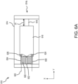
- FIG. 6A illustrates a cross section view of initiator 610 in a loaded position, or state.
- FIG. 6B illustrates a perspective view of initiator 610 in the loaded position. In the loaded position, lance body 616 and lance end 618 are retracted into housing 614 and spring 620 is compressed.
- First anchor point 624, second anchor point 626, third anchor point 628, and fourth anchor point are each coupled to lance body 616.
- first, second, third, and fourth anchor points 624, 626, 628 are each coupled to the first end 616a of lance body 616.
- first, second, third, and fourth anchor points 624, 626, 628 are coupled to an inner surface of lance body 616.
- first, second, third, and fourth anchor points 624, 626, 628 are coupled to an outer surface of lance body 616.
- first, second, third, and fourth anchor points 624, 626, 628 are spaced equidistant from each other (e.g., 90° offset from each other).
- first, second, third, and fourth anchor points 624, 626, 628 are spaced a variable distance from each other. In various embodiments, there may be more than four anchor points coupled to lance body 616.
- anchor points 630, 632, 634, 636 are coupled to housing 614.
- anchor points 630, 632, 634, 636 may be posts that extend away from first end 614a of housing 614 and toward lance body 616 (e.g., in the positive y-direction).
- anchor points 630, 632, 634, 636 may be hollow so that wire 622 passes through one or more of anchor points 630, 632, 634, 636.
- anchor points 630, 632, 634, 636 may be a knob, a pulley, a hook, or other feature to secure wire 622.
- anchor points 630, 632, 634, 636 may be spaced equidistance from each other (e.g., 90° offset from each other). In various embodiments, anchor points 630, 632, 634, 636 may be spaced a variable distance from each other. In various embodiments, anchor points 630, 632, 634, 636 may be interleaved between first, second, third, and fourth anchor points 624, 626, 628 so that, for example, each of anchor points 630, 632, 634, 636 is equidistant from each of first, second, third, and fourth anchor points 624, 626, 628 (e.g., 45° offset from each other).
- anchor points 630, 632, 634, 636, along with wire 622 may extend through the center of spring 620. In various embodiments, each anchor point 630, 632, 634, 636, along with wire 622, may extend around an outer circumference of spring 620 (as illustrated in FIG. 6B ).
- wire 622 passes through first end 614a into housing 614, wraps around fifth anchor point 630, wraps around first anchor point 624, wraps around sixth anchor point 632, wraps around second anchor point 626, wraps around seventh anchor point 634, wraps around third anchor point 628, wraps around eighth anchor point 636, wraps around the fourth anchor point and passes through first end 614a out of housing 614.
- first plurality of anchor points e.g., first, second, third, and fourth anchor points 624, 626, 628) that are coupled to lance body 616 and a second plurality of anchor points (e.g., anchor points 630, 632, 634, 636) coupled to first end 614a of housing 614.
- Wire 622 may enter housing 614, wrap alternatingly around the first plurality of anchor points and the second plurality of anchor points, and exit housing 614.
- wire 622 may be glued to one or more anchor points 624, 626, 628, 630, 632, 634, 636.
- wire 622 may be encased within one or more anchor points 624, 626, 628, 630, 632, 634, 636.
- wire 622 may enter and exit housing 614 through a single anchor point (e.g., fifth anchor point 630). In various embodiments, multiple wires 622 may be used where each wire 622 engages a different pair of anchor points. In various embodiments, each wire 622 may not be strong enough to hold spring 620 and a first wire 622 may break, or snap, in response to a second wire 622 breaking, or melting, in response to an electric current. In various embodiments, wire 622 may enter housing 614 adjacent an anchor point (e.g., fifth anchor point 630) and wrap around the adjacent anchor point.
- an anchor point e.g., fifth anchor point 630
- Initiator 710 includes similar components to those described above with respect to initiator 400 in FIGS. 4A and 4B including a housing 714 having a first end 714a, a second end 714b, and an opening 714c, a lance body 716 having a first end 716a and a second end 716b, a lance end 718 having a first end 718a and a second end 718b, a spring 720, and a wire 722, descriptions of which may not be repeated below. Initiator 710 further includes an anchor point 726 coupled to the first end 714a of housing 714.
- FIG. 7A illustrates a cross section view of initiator 710 in a loaded position, or state. In the loaded position, lance body 716 and lance end 718 are retracted into housing 714 and spring 720 is compressed.
- FIG. 7B illustrates a cross section view of initiator 710 in a deployed position, or state. In the deployed position, lance end 718 extends out of housing 714 and spring 720 is extended.
- FIGS. 7A and 7B illustrate spring 720 passing through the center of a tube shaped lance body 716.
- this configuration may be implemented in any of the previously described embodiments (e.g., initiators 410, 510, 610)
- lance body 716 may be a solid body with spring 720 engaging first end 716a of lance body 716.
- Wire 722 is coupled to anchor point 726 at one end and to lance body 716 at the other end.
- wire 722 may be coupled to first end 716a of lance body 716.
- wire 722 may be coupled to second end 716b of lance body 716 (as illustrated in FIG. 7A ).
- references to "one embodiment,” “an embodiment,” “various embodiments,” etc. indicate that the embodiment described may include a particular feature, structure, or characteristic, but every embodiment may not necessarily include the particular feature, structure, or characteristic. Moreover, such phrases are not necessarily referring to the same embodiment. Further, when a particular feature, structure, or characteristic is described in connection with an embodiment, it is submitted that it is within the knowledge of one skilled in the art to affect such feature, structure, or characteristic in connection with other embodiments whether or not explicitly described. After reading the description, it will be apparent to one skilled in the relevant art(s) how to implement the disclosure in alternative embodiments.
- Numbers, percentages, or other values stated herein are intended to include that value, and also other values that are about or approximately equal to the stated value, as would be appreciated by one of ordinary skill in the art encompassed by various embodiments of the present disclosure.
- a stated value should therefore be interpreted broadly enough to encompass values that are at least close enough to the stated value to perform a desired function or achieve a desired result.
- the stated values include at least the variation to be expected in a suitable industrial process, and may include values that are within 5% of a stated value.
- the terms “substantially,” “about” or “approximately” as used herein represent an amount close to the stated amount that still performs a desired function or achieves a desired result.
- the term “substantially,” “about” or “approximately” may refer to an amount that is within 5% of a stated amount or value.
Landscapes
- Engineering & Computer Science (AREA)
- General Engineering & Computer Science (AREA)
- Mechanical Engineering (AREA)
- Filling Or Discharging Of Gas Storage Vessels (AREA)
- Air Bags (AREA)
- Fuses (AREA)
Abstract
Description
- The present disclosure generally relates compressed fluid sources, and more particularly, to compressed fluid source initiators.
- Oxygen systems may be used in aircraft that typically include a pressurized fluid cylinder, a manifold, and an initiator to puncture a seal of the pressurized fluid cylinder. Typically, the initiator uses a pyrotechnic chemical to fire a lance of the initiator toward the seal of the pressurized fluid source.
- An emergency evacuation assembly may be used to exit an aircraft absent a jet way or other suitable means of egress for passengers. The evacuation assembly may include an inflatable slide and one or more compressed fluid source(s) configured to inflate the slide. Current compressed fluid sources may include an initiator valve assembly configured to open in response to deployment of the evacuation slide, thereby allowing fluid to flow to the evacuation slide.
- Currently, compressed fluid sources or compressed gas cylinders use a valve module that is directly assembled to the cylinder that allows the compressed gas to exit the cylinder. The valve may also be used to fill the cylinder with gas. However, the valve may be prone to leaking air from the cylinder over time. Additionally, the valve may be generally attached to the cylinder using a threaded interface and a static seal at the threaded interface that may be prone to leaking over time.
- Disclosed herein is an initiator for opening a pressurized gas cylinder. The initiator includes a housing having a first end and a second end, a lance disposed within the housing, the lance configured to slide from the first end of the housing to the second end of the housing and out through the second end of the housing, a spring disposed within the housing between the first end of the housing and the lance, and a wire coupled to the first end of the housing and to the lance, the wire configured to hold the spring in a compressed state, the wire further configured to break in response to an electric current.
- In various embodiments, the lance further includes a lance body configured to stay within the housing, wherein the wire is coupled to the lance body, and a lance end coupled to the lance body and configured to pass through the second end of the housing. In various embodiments, the initiator further includes an anchor point coupled to the lance, wherein the wire is configured to enter the housing, wrap around the anchor point, and exit the housing.
- In various embodiments, the initiator further includes a first anchor point coupled to the lance, a second anchor point coupled to the lance, and a third anchor point coupled to the housing, wherein the wire is configured to enter the housing, wrap around the first anchor point, wrap around the third anchor point, wrap around the second anchor point, and exit the housing.
- In various embodiments, the initiator further includes a first plurality of anchor points coupled to the lance, and a second plurality of anchor points coupled to the housing, the wire configured to enter the housing, wrap alternately around the first plurality of anchor points and the second plurality of anchor points, and exit the housing. In various embodiments, the first plurality of anchor points are spaced around the lance and equidistant from each other, and wherein the second plurality of anchor points are spaced around the first end of the housing and equidistant from each other. In various embodiments, the lance is hollow and has a first end adjacent the first end of the housing and a second end, wherein the spring is disposed between the first end of the housing and the second end of the lance.
- Also disclosed herein is a system including a compressed gas cylinder and an initiator configured to open the compressed gas cylinder. The initiator includes a housing having a first end and a second end, a lance disposed within the housing, the lance configured to slide from the first end of the housing to the second end of the housing and out through the second end of the housing, a spring disposed within the housing between the first end of the housing and the lance, and a wire coupled to the first end of the housing and to the lance, the wire configured to hold the spring in a compressed state, the wire further configured to break in response to an electric current.
- In various embodiments, the lance further includes a lance body configured to stay within the housing, wherein the wire is coupled to the lance body and a lance end coupled to the lance body and configured to pass through the second end of the housing. In various embodiments, the initiator further includes an anchor point coupled to the lance, wherein the wire is configured to enter the housing, wrap around the anchor point, and exit the housing.
- In various embodiments, the initiator further includes a first anchor point coupled to the lance, a second anchor point coupled to the lance, and a third anchor point coupled to the housing, wherein the wire is configured to enter the housing, wrap around the first anchor point, wrap around the third anchor point, wrap around the second anchor point, and exit the housing.
- In various embodiments the initiator further includes a first plurality of anchor points coupled to the lance and a second plurality of anchor points coupled to the housing, the wire configured to enter the housing, wrap alternately around the first plurality of anchor points and the second plurality of anchor points, and exit the housing. In various embodiments, the first plurality of anchor points are spaced around the lance and equidistant from each other, and wherein the second plurality of anchor points are spaced around the first end of the housing and equidistant from each other.
- In various embodiments, the lance is hollow and has a first end adjacent the first end of the housing and a second end, wherein the spring is disposed between the first end of the housing and the second end of the lance.
- Also disclosed herein is a system including a pressurized cylinder, a manifold coupled to the pressurized cylinder, and an initiator coupled to the manifold and configured to open the pressurized cylinder. The initiator includes a housing having a first end and a second end, a lance disposed within the housing, the lance configured to slide from the first end of the housing to the second end of the housing and out through the second end of the housing, a spring disposed within the housing between the first end of the housing and the lance, and a wire coupled to the first end of the housing and to the lance, the wire configured to hold the spring in a compressed state, the wire further configured to break in response to an electric current.
- In various embodiments, the lance further includes a lance body configured to stay within the housing, wherein the wire is coupled to the lance body and a lance end coupled to the lance body and configured to pass through the second end of the housing. In various embodiments, the initiator further includes an anchor point coupled to the lance, wherein the wire is configured to enter the housing, wrap around the anchor point, and exit the housing.
- In various embodiments, the initiator further includes a first anchor point coupled to the lance, a second anchor point coupled to the lance, and a third anchor point coupled to the housing, wherein the wire is configured to enter the housing, wrap around the first anchor point, wrap around the third anchor point, wrap around the second anchor point, and exit the housing.
- In various embodiments, the initiator further includes a first plurality of anchor points coupled to the lance and a second plurality of anchor points coupled to the housing, the wire configured to enter the housing, wrap alternately around the first plurality of anchor points and the second plurality of anchor points, and exit the housing. In various embodiments, the first plurality of anchor points are spaced around the lance and equidistant from each other, and wherein the second plurality of anchor points are spaced around the first end of the housing and equidistant from each other.
- The foregoing features and elements may be combined in any combination, without exclusivity, unless expressly indicated herein otherwise. These features and elements as well as the operation of the disclosed embodiments will become more apparent in light of the following description and accompanying drawings.
- The subject matter of the present disclosure is particularly pointed out and distinctly claimed in the concluding portion of the specification. A more complete understanding of the present disclosure, however, may best be obtained by referring to the following detailed description and claims in connection with the following drawings. While the drawings illustrate various embodiments employing the principles described herein, the drawings do not limit the scope of the claims.
-
FIG. 1 illustrates an aircraft, in accordance with various embodiments. -
FIG. 2 illustrates an evacuation assembly including an evacuation slide and a compressed fluid source, in accordance with various embodiments. -
FIGS. 3A and3B illustrate a compressed fluid cylinder manifold and initiator, in accordance with various embodiments. -
FIGS. 4A and 4B illustrate an electronically activated, spring loaded initiator for opening compressed gas cylinders. -
FIGS. 5A and 5B illustrate an electronically activated, spring loaded initiator for opening compressed gas cylinders. -
FIGS. 6A and6B illustrate an electronically activated, spring loaded initiator for opening compressed gas cylinders. -
FIGS. 7A and 7B illustrate an electronically activated, spring loaded initiator for opening compressed gas cylinders. - The following detailed description of various embodiments herein makes reference to the accompanying drawings, which show various embodiments by way of illustration. While these various embodiments are described in sufficient detail to enable those skilled in the art to practice the disclosure, it should be understood that other embodiments may be realized and that changes may be made without departing from the scope of the invention as defined by the claims. Thus, the detailed description herein is presented for purposes of illustration only and not of limitation. For example, the steps recited in any of the method or process descriptions may be executed in any order and are not necessarily limited to the order presented. Furthermore, any reference to singular includes plural embodiments, and any reference to more than one component or step may include a singular embodiment or step. Also, any reference to attached, fixed, connected, or the like may include permanent, removable, temporary, partial, full or any other possible attachment option. Additionally, any reference to without contact (or similar phrases) may also include reduced contact or minimal contact. It should also be understood that unless specifically stated otherwise, references to "a," "an" or "the" may include one or more than one and that reference to an item in the singular may also include the item in the plural. Further, all ranges may include upper and lower values and all ranges and ratio limits disclosed herein may be combined.
- Disclosed herein are is an electrically activated, spring loaded initiator for opening a compressed fluid source such as a compressed gas cylinder. In various embodiments, the compressed fluid source may be used to inflate an inflatable (e.g., a life raft, an emergency slide, etc.) or to provide oxygen to a compartment (e.g., cockpit, storage bay, passenger cabin, etc.) among others. In various embodiments, the initiator may be coupled to a manifold that is coupled to the compressed fluid source. In various embodiments, the initiator includes a housing, a lance, a spring, and a fuse wire. In various embodiments, the initiator is packed to an initial depth of a loaded state, compressing the spring, and held at the initial depth using the fuse wire. In various embodiments, the tensile strength of the fuse wire holds the initiator in the loaded state until the initiator is activated. In various embodiments, the fuse wire breaks, or melts, in response to an electric current, thereby allowing the lance to deploy and open the compressed fluid source. In various embodiments, the spring pressure holds the lance forward after being deployed to ensure the release of all, or substantially all, of the gas in the pressurized fluid source.
- In various embodiments, the fuse wire may be tested for electric continuity to ensure that the fuse wire has not broken and that the initiator remains usable. In various embodiments, the fuse wire is coupled to the lance using a lever, a pulley, a knob, a pin, or a bar, among others, to increase the mechanical advantage of the fuse wire to hold the spring in the loaded state. In various embodiments, more than a one lever, pulley, knob, pin, or bar may be used and the fuse wire may be wrapped around, or secured to, each of the multiple levers, pulleys, knobs, and/or bars to increase the mechanical advantage of the fuse wire to hold the spring in the loaded state.
- The initiator as disclosed herein obviates the pyrotechnic lances that currently propels the lance to open the pressurized fluid source. This increases the number of locations that the initiator can be used while, in various embodiments, reducing the complexity and safety issues associated with pyrotechnic lances. Furthermore, the initiator as disclosed herein, in various embodiments, uses fewer O-rings and/or interfaces than initiators that are currently in use. In various embodiments, the initiator as disclosed herein reduces, or removes, the use of a quick-release mechanisms that are currently in use with various initiators. Other benefits and advantages will be apparent to those of skill in the art.
- Referring now to
FIG. 1 , anaircraft 100 is shown.Aircraft 100 may include afuselage 102 having plurality of exit doors, includingexit door 104.Aircraft 100 may include one or more evacuation assemblies positioned near a corresponding exit door. For example,aircraft 100 includes anevacuation assembly 106 positioned nearexit door 104. In the event of an emergency,exit door 104 may be opened by a passenger or crew member ofaircraft 100. In various embodiments,evacuation assembly 106 may deploy in response to exitdoor 104 being opened or in response to another action taken by a passenger or crew member, such as the depression of a button, the actuation of a lever, or the like. - With reference to
FIG. 2 , additional details ofevacuation assembly 106 are illustrated. In accordance with various embodiments,evacuation assembly 106 includes anevacuation slide 120 and a compressedfluid source 130. In accordance with various embodiments,evacuation slide 120 includes atoe end 122 and ahead end 124opposite toe end 122.Head end 124 may be coupled to an aircraft structure (e.g.,fuselage 102 inFIG. 1 ). In accordance with various embodiments,evacuation slide 120 is an inflatable slide.Evacuation slide 120 includes a slidingsurface 126 and anunderside surface 128 opposite slidingsurface 126. Slidingsurface 126 extends fromhead end 124 to toeend 122. During an evacuation event,underside surface 128 may be oriented toward an exit surface (e.g., toward the ground or toward a body of water).Evacuation slide 120 is illustrated as a single lane slide; however,evacuation slide 120 may comprise any number of lanes. -
Evacuation assembly 106 includes compressed fluid source 130 (also referred to as a charge cylinder, compressed gas cylinder, or gas cylinder). Compressedfluid source 130 is configured to deliver a pressurized gas to inflateevacuation slide 120. Compressedfluid source 130 is fluidly coupled toevacuation slide 120. For example, compressedfluid source 130 may be fluidly coupled toevacuation slide 120 via a hose, or conduit, 132. In response to receiving gas from compressedfluid source 130,evacuation slide 120 begins to inflate. - In accordance with various embodiments,
conduit 132 may be connected to avalve outlet 138 of avalve assembly 140 fluidly coupled to compressedfluid source 130. In this regard,valve assembly 140 is fluidly coupled between compressedfluid source 130 andconduit 132.Valve assembly 140 is configured to regulate the flow of fluid from compressedfluid source 130 toevacuation slide 120. In this regard, whenevacuation slide 120 is in a stowed (or deflated) state,valve assembly 140 is in a closed position. In response to deployment ofevacuation assembly 106,valve assembly 140 translates to an open position, thereby allowing fluid to flow from compressedfluid source 130 toevacuation slide 120. - Referring now to
FIGS. 3A and3B , in accordance with various embodiments, cross section views of avalve assembly 300 for opening apressurized cylinder 302 is illustrated.FIG. 3A illustrates a cross section view ofactuation device 300 in a closed position.FIG. 3B illustrates a cross section view ofactuation device 300 in an open position. In various embodiments,valve assembly 300 may be an example ofvalve assembly 140 described above inFIG. 2 . In various embodiments,pressurized cylinder 302 may be an example of compressedfluid source 130 described above inFIG. 2 .Pressurized cylinder 302 includes anopening 304, metal inserts 306, and afracture disk 308. Metal inserts 306 are connected to opening 304 and around the circumference ofopening 304. In various embodiments, metal inserts 306 may be welded to opening 304 ofpressurized cylinder 302.Fracture disk 308, also referred to as a diaphragm, is connected to metal inserts 306. In various embodiments,pressurized cylinder 302 is hermetically sealed. In various embodiments,pressurized cylinder 302 may be filled with pressurized gas from a bottom portion (e.g., the negative y-direction) ofpressurized cylinder 302. -
Valve assembly 300 includes an electronically activated, spring-driven initiator,initiator 310, and a manifold 312, where the manifold 312 is configured to receiveinitiator 310 and connect topressurized cylinder 302. In various embodiments,manifold 312 is threaded ontopressurized cylinder 302.Initiator 310 is configured to puncture, or break,fracture disk 308 to release the gas stored inpressurized cylinder 302 in response to an electric current.Manifold 312 includes anair outlet 313 that may be connected to an inflatable slide (e.g., evacuation slide 120), an inflatable raft, or an oxygen system, among other applications. In various embodiments, the gas stored in pressurized cylinder may flow frompressurized cylinder 302, throughopening 304, and throughair outlet 313 into the inflatable in response tofracture disk 308 being broken, or punctured. In various embodiments,initiator 310 may be used to open a manifold, or other pressurized and/or sealed components. -
Initiator 310 includes ahousing 314, alance body 316, alance end 318, aspring 320, awire 322, and ananchor point 324.Lance body 316 andlance end 318 may be collectively referred to as a lance. In various embodiments,initiator 310 may be cylindrical in shape so thathousing 314 may be cylindrical in shape having a circular first end (e.g., in the positive y-direction), a circular bottom end (e.g., in the negative y-direction), and an outer wall extending from the first end to the second and circumferentially aroundlance body 316. In various embodiments,lance body 316 may also be cylindrical in shape. In various embodiments,spring 320 is configured to engage a first end of lance body 316 (e.g., in the positive y-direction). In various embodiments,lance body 316 may be tubular in shape having a hollow center that is configured to receivespring 320. - Lance end 318 includes a first end (e.g., in the positive y-direction) and a second end (e.g., in the negative y-direction). In various embodiments, the first end of
lance end 318 is coupled to a second end of lance body 316 (e.g., in the negative y-direction) and is configured to puncture, or break,fracture disk 308. Accordingly,housing 314 includes an opening in the second end (e.g. in the negative y-direction) that allowslance end 318 to pass throughhousing 314 to engage and breakfracture disk 308. In various embodiments, the second end oflance end 318 may be blunt. In various embodiments, the second end oflance end 318 may be sharp to more efficiently breakfracture disk 308. In various embodiments, the second end oflance end 318 may be frustoconical or conical in shape. -
Anchor point 324 is coupled at or near the first end oflance body 316.Wire 322, also referred to as a fuse wire, passes throughhousing 314, aroundanchor point 324, and back throughhousing 314. This configuration increases the mechanical advantage ofwire 322 enablingwire 322 to exert more force onspring 320.Wire 322 is configured to melt in response to an electric current and break, similar to a fuse. This creates a single point of failure that releases the tension inwire 322 in response towire 322 melting, or breaking. In various embodiments, a first electric current that is above a melt threshold may be used to triggerinitiator 310 by meltingwire 322. In various embodiments, a second electric current that is less than the melt threshold may be used to testwire 322 for continuity (i.e., no breaks) to ensure thatinitiator 310 is usable.FIG. 3A illustratesinitiator 310 in a loaded position, or state, andpressurized cylinder 302 is closed.FIG. 3B illustratesinitiator 310 in a deployed position, or state andpressurized cylinder 302 is opened. In response to deployment of an evacuation assembly (e.g., evacuation assembly 106), an electric current is passed throughwire 322 which causeswire 322 to break, thereby causinginitiator 310 to move from the loaded position to the deployed position. In response towire 322 breaking,spring 320 extends pushinglance body 316, and byextension lance end 318, towardpressurized cylinder 302 and fracture disk 308 (e.g., in the negative y-direction) with sufficient force to breakfracture disk 308. The gas inpressurized cylinder 302 escapespressurized cylinder 302 throughopening 304 and throughair outlet 313 in response tofracture disk 308 being broken byinitiator 310. - Referring now to
FIGS. 4A and 4B , an electronically activated, spring driven initiator, initiator 400, is illustrated, in accordance with various embodiments.Initiator 410 includes similar components to those described above with respect toinitiator 310 inFIGS. 3A and3B , including ahousing 414, alance body 416, alance end 418, aspring 420, awire 422, and ananchor point 424, descriptions of which may not be repeated below.FIG. 4A illustrates a cross section view ofinitiator 410 in a loaded position, or state. In the loaded position,lance body 416 andlance end 418 are retracted intohousing 414 andspring 420 is compressed. In various embodiments,lance end 418 may exposed and protrude from housing 414 (e.g., in the positive y-direction) whileinitiator 410 is in the loaded position.FIG. 4B illustrates a cross section view ofinitiator 410 in a deployed position, or state. In the deployed position,lance end 418 extends out ofhousing 414 andspring 420 is extended.Lance body 416 andlance end 418 move a distance d1 from the loaded position to the deployed position. In various, embodiments, distance d1 is about 0.1 inches (about 0.254 centimeter) to about 1.0 inches (about 2.54 centimeters), and more specifically, about 0.25 inches (about 0.635 centimeter) to about 0.5 inches (about 1.27 centimeters). -
Housing 414 has afirst end 414a, asecond end 414b, and anopening 414c insecond end 414b. In various embodiments,housing 414 may be cylindrical in shape.Housing 414 encloseslance body 416,spring 420, and at least a portion oflance end 418.Lance body 416 is configured to slide (e.g., along the y-axis) withinhousing 414. In various embodiments, an outer surface oflance body 416 may be in contact with an inner surface ofhousing 414. In various embodiments, there may be a gap between the outer surface oflance body 416 and the inner surface ofhousing 414. In various embodiments, the gap may be configured to allow a fluid, or gas, to pass throughhousing 414. In various embodiments,housing 414 may further include an anti-friction sleeve and/or O-rings between the outer surface oflance body 416 and theinner surface housing 414. -
Lance body 416 has afirst end 416a and asecond end 416b. Lance end 418 has afirst end 418a and asecond end 418b.Spring 420 is in contact with an inner surface offirst end 414a ofhousing 414 at a first end and in contact withfirst end 416a oflance body 416 at a second end. In various embodiments,lance body 416 may be solid such that the second end ofspring 420 contacts an outer edge offirst end 416a oflance body 416. In various embodiments,lance body 416 may be hollow such that the second end ofspring 420 contacts an inner surface oflance body 416 between thefirst end 416a and thesecond end 416b. In various embodiments, the second end ofspring 420 may contact the inner surface oflance body 416 adjacentsecond end 416b. By extending intolance body 416,spring 420 is held in line andlance body 416 reduces bowing ofspring 420 as it extends. Either configuration provides sufficient energy to propellance end 418 to open a pressurized gas cylinder (e.g., pressurized cylinder 302). -
Wire 422 extends throughfirst end 414a ofhousing 414, wraps aroundanchor point 424, and extends back throughfirst end 414a so that two strands ofwire 422hold spring 420 compressed in the loaded position. This configuration provides a mechanical advantage that increases the effective tensile strength ofwire 422 without increasing the size ofwire 422.Initiator 410 may be designed to balance the size, and strength, ofspring 420, the size ofwire 422, and an amount of current used to break, or melt,wire 422. By increasing the mechanical advantage ofwire 422, asmaller wire 422 may break at a lower current and while restrainingspring 420 that is larger than possible with a single strand ofwire 422. -
Anchor point 424 is coupled tofirst end 416a oflance body 416. In various embodiments,anchor point 424 may include a pin, a hook, a nub, a protrusion, or a bolt head, among others, to holdwire 422 in place. In such embodiments,anchor point 424 may be coupled to an outer surface oflance body 416 or an inner surface oflance body 416. In various embodiments,anchor point 424 may include a rod, or cylinder, that extends across a diameter oflance body 416. In such embodiments,wire 422 may extend through a center ofspring 420 to engageanchor point 424. - Referring now to
FIGS. 5A and 5B , an electronically activated, spring driven initiator,initiator 510, is illustrated, in accordance with various embodiments.Initiator 510 includes similar components to those described above with respect toinitiator 410 inFIGS. 4A and 4B including ahousing 514 having afirst end 514a, asecond end 514b, and anopening 514c, alance body 516 having afirst end 516a and asecond end 516b, alance end 518 having afirst end 518a and asecond end 518b, aspring 520, awire 522, and afirst anchor point 524, descriptions of which may not be repeated below.FIG. 5A illustrates a cross section view ofinitiator 510 in a loaded position, or state. In the loaded position,lance body 516 andlance end 518 are retracted intohousing 514 andspring 520 is compressed.FIG. 5B illustrates a cross section view ofinitiator 510 in a deployed position, or state. In the deployed position,lance end 518 extends outhousing 514 andspring 520 is extended.Initiator 510 further includes asecond anchor point 526 and athird anchor point 528. -
First anchor point 524 andsecond anchor point 526 are coupled to lancebody 516, similar toanchor point 424 described above inFIGS. 4A and 4B .Third anchor point 528 is coupled tohousing 514, and more specifically, tofirst end 514a ofhousing 514. As illustrated inFIG. 5A ,wire 522 passes throughfirst end 514a intohousing 514, wraps aroundfirst anchor point 524, wraps aroundthird anchor point 528, wraps aroundsecond anchor point 526, and passes throughfirst end 514a out ofhousing 514. This configuration improves the mechanical advantage ofwire 522 by providing, effectively, four lengths ofwire 522 to holdspring 520 compressed and in the loaded state. In various embodiments, this configuration allows for the use of astrong spring 520. In various embodiments, this configuration allows for the use of aweaker wire 522 which results in the use of less electric current to break, or melt,wire 522 during actuation ofinitiator 510. - As previously described, and in various embodiments,
wire 522 may pass through the center ofspring 520. In various embodiments,first anchor point 524 andsecond anchor point 526 may be coupled to an inside surface oflance body 516. In various embodiments,first anchor point 524 may be adjacentsecond anchor point 526. In various embodiments,first anchor point 524 may be oppositesecond anchor point 526. In various embodiments,wire 522 may be located around an outer circumference ofspring 520. - Referring now to FIGS. 6A-6C, an electronically activated, spring driven initiator,
initiator 610, is illustrated, in accordance with various embodiments.Initiator 610 includes similar components to those described above with respect toinitiator 410 inFIGS. 4A and 4B including ahousing 614 having afirst end 614a, asecond end 614b, and anopening 614c, alance body 616 having afirst end 616a and asecond end 616b, alance end 618 having afirst end 618a and asecond end 618b, aspring 620, awire 622, and afirst anchor point 624, descriptions of which may not be repeated below.Initiator 610 further includes asecond anchor point 626, athird anchor point 628, a fourth anchor point, afifth anchor point 630, asixth anchor point 632, aseventh anchor point 634, and an eightanchor point 636.FIG. 6A illustrates a cross section view ofinitiator 610 in a loaded position, or state.FIG. 6B illustrates a perspective view ofinitiator 610 in the loaded position. In the loaded position,lance body 616 andlance end 618 are retracted intohousing 614 andspring 620 is compressed. -
First anchor point 624,second anchor point 626,third anchor point 628, and fourth anchor point are each coupled tolance body 616. In various embodiments, first, second, third, and fourth anchor points 624, 626, 628 are each coupled to thefirst end 616a oflance body 616. In various embodiments, first, second, third, and fourth anchor points 624, 626, 628 are coupled to an inner surface oflance body 616. In various embodiments, first, second, third, and fourth anchor points 624, 626, 628 are coupled to an outer surface oflance body 616. In various embodiments, first, second, third, and fourth anchor points 624, 626, 628 are spaced equidistant from each other (e.g., 90° offset from each other). In various embodiments, first, second, third, and fourth anchor points 624, 626, 628, are spaced a variable distance from each other. In various embodiments, there may be more than four anchor points coupled tolance body 616. -
Fifth anchor point 630,sixth anchor point 632,seventh anchor point 634, and eightanchor point 636 are coupled tohousing 614. In various embodiments, anchor points 630, 632, 634, 636 may be posts that extend away fromfirst end 614a ofhousing 614 and toward lance body 616 (e.g., in the positive y-direction). In various embodiments, anchor points 630, 632, 634, 636 may be hollow so thatwire 622 passes through one or more of anchor points 630, 632, 634, 636. In various embodiments, anchor points 630, 632, 634, 636 may be a knob, a pulley, a hook, or other feature to securewire 622. In various embodiments, anchor points 630, 632, 634, 636 may be spaced equidistance from each other (e.g., 90° offset from each other). In various embodiments, anchor points 630, 632, 634, 636 may be spaced a variable distance from each other. In various embodiments, anchor points 630, 632, 634, 636 may be interleaved between first, second, third, and fourth anchor points 624, 626, 628 so that, for example, each of anchor points 630, 632, 634, 636 is equidistant from each of first, second, third, and fourth anchor points 624, 626, 628 (e.g., 45° offset from each other). - In various embodiments, anchor points 630, 632, 634, 636, along with
wire 622, may extend through the center ofspring 620. In various embodiments, eachanchor point wire 622, may extend around an outer circumference of spring 620 (as illustrated inFIG. 6B ). - In the illustrated embodiment,
wire 622 passes throughfirst end 614a intohousing 614, wraps aroundfifth anchor point 630, wraps aroundfirst anchor point 624, wraps aroundsixth anchor point 632, wraps aroundsecond anchor point 626, wraps aroundseventh anchor point 634, wraps aroundthird anchor point 628, wraps aroundeighth anchor point 636, wraps around the fourth anchor point and passes throughfirst end 614a out ofhousing 614. In other words, That is to say, there may be a first plurality of anchor points (e.g., first, second, third, and fourth anchor points 624, 626, 628) that are coupled to lancebody 616 and a second plurality of anchor points (e.g., anchor points 630, 632, 634, 636) coupled tofirst end 614a ofhousing 614.Wire 622 may enterhousing 614, wrap alternatingly around the first plurality of anchor points and the second plurality of anchor points, and exithousing 614. In various embodiments,wire 622 may be glued to one or more anchor points 624, 626, 628, 630, 632, 634, 636. In various embodiments,wire 622 may be encased within one or more anchor points 624, 626, 628, 630, 632, 634, 636. - In various embodiments,
wire 622 may enter and exithousing 614 through a single anchor point (e.g., fifth anchor point 630). In various embodiments,multiple wires 622 may be used where eachwire 622 engages a different pair of anchor points. In various embodiments, eachwire 622 may not be strong enough to holdspring 620 and afirst wire 622 may break, or snap, in response to asecond wire 622 breaking, or melting, in response to an electric current. In various embodiments,wire 622 may enterhousing 614 adjacent an anchor point (e.g., fifth anchor point 630) and wrap around the adjacent anchor point. - Referring now to
FIGS. 7A and 7B , an electronically activated, spring driven initiator, initiator 700, is illustrated, in accordance with various embodiments.Initiator 710 includes similar components to those described above with respect to initiator 400 inFIGS. 4A and 4B including ahousing 714 having afirst end 714a, asecond end 714b, and anopening 714c, alance body 716 having afirst end 716a and asecond end 716b, alance end 718 having afirst end 718a and asecond end 718b, aspring 720, and awire 722, descriptions of which may not be repeated below.Initiator 710 further includes ananchor point 726 coupled to thefirst end 714a ofhousing 714.FIG. 7A illustrates a cross section view ofinitiator 710 in a loaded position, or state. In the loaded position,lance body 716 andlance end 718 are retracted intohousing 714 andspring 720 is compressed.FIG. 7B illustrates a cross section view ofinitiator 710 in a deployed position, or state. In the deployed position,lance end 718 extends out ofhousing 714 andspring 720 is extended. -
FIGS. 7A and 7B illustratespring 720 passing through the center of a tube shapedlance body 716. In various embodiments, this configuration may be implemented in any of the previously described embodiments (e.g.,initiators lance body 716 may be a solid body withspring 720 engagingfirst end 716a oflance body 716.Wire 722 is coupled toanchor point 726 at one end and to lancebody 716 at the other end. In various embodiments,wire 722 may be coupled tofirst end 716a oflance body 716. In various embodiments,wire 722 may be coupled tosecond end 716b of lance body 716 (as illustrated inFIG. 7A ). - Benefits, other advantages, and solutions to problems have been described herein with regard to specific embodiments. Furthermore, the connecting lines shown in the various figures contained herein are intended to represent exemplary functional relationships and/or physical couplings between the various elements. It should be noted that many alternative or additional functional relationships or physical connections may be present in a practical system. However, the benefits, advantages, solutions to problems, and any elements that may cause any benefit, advantage, or solution to occur or become more pronounced are not to be construed as critical, required, or essential features or elements of the disclosure. The scope of the disclosure is accordingly to be limited by nothing other than the appended claims, in which reference to an element in the singular is not intended to mean "one and only one" unless explicitly so stated, but rather "one or more." Moreover, where a phrase similar to "at least one of A, B, or C" is used in the claims, it is intended that the phrase be interpreted to mean that A alone may be present in an embodiment, B alone may be present in an embodiment, C alone may be present in an embodiment, or that any combination of the elements A, Band C may be present in a single embodiment; for example, A and B, A and C, B and C, or A and B and C. Different cross-hatching is used throughout the figures to denote different parts but not necessarily to denote the same or different materials.
- Systems, methods, and apparatus are provided herein. In the detailed description herein, references to "one embodiment," "an embodiment," "various embodiments," etc., indicate that the embodiment described may include a particular feature, structure, or characteristic, but every embodiment may not necessarily include the particular feature, structure, or characteristic. Moreover, such phrases are not necessarily referring to the same embodiment. Further, when a particular feature, structure, or characteristic is described in connection with an embodiment, it is submitted that it is within the knowledge of one skilled in the art to affect such feature, structure, or characteristic in connection with other embodiments whether or not explicitly described. After reading the description, it will be apparent to one skilled in the relevant art(s) how to implement the disclosure in alternative embodiments.
- Numbers, percentages, or other values stated herein are intended to include that value, and also other values that are about or approximately equal to the stated value, as would be appreciated by one of ordinary skill in the art encompassed by various embodiments of the present disclosure. A stated value should therefore be interpreted broadly enough to encompass values that are at least close enough to the stated value to perform a desired function or achieve a desired result. The stated values include at least the variation to be expected in a suitable industrial process, and may include values that are within 5% of a stated value. Additionally, the terms "substantially," "about" or "approximately" as used herein represent an amount close to the stated amount that still performs a desired function or achieves a desired result. For example, the term "substantially," "about" or "approximately" may refer to an amount that is within 5% of a stated amount or value.
- Furthermore, no element, component, or method step in the present disclosure is intended to be dedicated to the public regardless of whether the element, component, or method step is explicitly recited in the claims. No claim element herein is to be construed under the provisions of 35 U.S.C. 312(f) unless the element is expressly recited using the phrase "means for." As used herein, the terms "comprises," "comprising," or any other variation thereof, are intended to cover a non-exclusive inclusion, such that a process, method, article, or apparatus that comprises a list of elements does not include only those elements but may include other elements not expressly listed or inherent to such process, method, article, or apparatus.
- Finally, it should be understood that any of the above-described concepts can be used alone or in combination with any or all of the other above-described concepts. Although various embodiments have been disclosed and described, one of ordinary skill in this art would recognize that certain modifications would come within the scope of the invention as defined by the claims.
Claims (9)
- An initiator for opening a pressurized gas cylinder, comprising:a housing (414) having a first end (414a) and a second end (414b);a lance (416, 418) disposed within the housing, the lance configured to slide from the first end of the housing to the second end of the housing and out through the second end of the housing;a spring (420) disposed within the housing between the first end of the housing and the lance; anda wire (422) coupled to the first end of the housing and to the lance, the wire configured to hold the spring in a compressed state, the wire further configured to break in response to an electric current.
- The initiator for opening the pressurized gas cylinder of claim 1, wherein the lance further comprises:a lance body (416) configured to stay within the housing, wherein the wire is coupled to the lance body; anda lance end (418) coupled to the lance body and configured to pass through the second end of the housing.
- The initiator for opening the pressurized gas cylinder of claim 1 or 2, further comprising:
an anchor point (424) coupled to the lance, wherein the wire is configured to enter the housing, wrap around the anchor point, and exit the housing. - The initiator for opening the pressurized gas cylinder of claim 1 or 2, further comprising:a first anchor point (524) coupled to the lance;a second anchor point (526) coupled to the lance; anda third anchor point (528) coupled to the housing, wherein the wire is configured to enter the housing, wrap around the first anchor point, wrap around the third anchor point, wrap around the second anchor point, and exit the housing.
- The initiator for opening the pressurized gas cylinder of claim 1 or 2, further comprising:a first plurality of anchor points coupled to the lance; anda second plurality of anchor points coupled to the housing, the wire configured to enter the housing, wrap alternately around the first plurality of anchor points and the second plurality of anchor points, and exit the housing.
- The initiator for opening the pressurized gas cylinder of claim 5, wherein the first plurality of anchor points are spaced around the lance and equidistant from each other, and wherein the second plurality of anchor points are spaced around the first end of the housing and equidistant from each other.
- The initiator for opening the pressurized gas cylinder of any preceding claim 1, wherein the lance is hollow and has a first end adjacent the first end of the housing and a second end, wherein the spring (420) is disposed between the first end of the housing and the second end of the lance.
- A system, comprising:a compressed gas cylinder (302); andan initiator (310) as claimed in any preceding claim configured to open the compressed gas cylinder.
- A system, comprising:a pressurized cylinder (302);a manifold (312) coupled to the pressurized cylinder; andan initiator (310) as claimed in any of claims 1 to 7 coupled to the manifold and configured to open the pressurized cylinder.
Applications Claiming Priority (1)
| Application Number | Priority Date | Filing Date | Title |
|---|---|---|---|
| US18/446,158 US12460776B2 (en) | 2023-08-08 | 2023-08-08 | Electronically activated, spring-driven initiator |
Publications (1)
| Publication Number | Publication Date |
|---|---|
| EP4506612A1 true EP4506612A1 (en) | 2025-02-12 |
Family
ID=92264113
Family Applications (1)
| Application Number | Title | Priority Date | Filing Date |
|---|---|---|---|
| EP24193403.3A Pending EP4506612A1 (en) | 2023-08-08 | 2024-08-07 | Electronically activated, spring-driven initiator |
Country Status (2)
| Country | Link |
|---|---|
| US (1) | US12460776B2 (en) |
| EP (1) | EP4506612A1 (en) |
Citations (4)
| Publication number | Priority date | Publication date | Assignee | Title |
|---|---|---|---|---|
| US3008479A (en) * | 1959-02-10 | 1961-11-14 | Altair Inc | Valves |
| US5509576A (en) * | 1992-07-14 | 1996-04-23 | Halkey-Roberts Corporation | Electric autoinflator |
| KR20200061091A (en) * | 2018-11-23 | 2020-06-02 | 세이프웨어(주) | Inflator using electrical impulse and protective gear using the same |
| US20220055722A1 (en) * | 2020-08-24 | 2022-02-24 | Mark A. Gummin | Shape memory alloy actuator for inflation device |
Family Cites Families (10)
| Publication number | Priority date | Publication date | Assignee | Title |
|---|---|---|---|---|
| US824934A (en) * | 1905-05-10 | 1906-07-03 | Adolph W Jenczewsky | Safety-valve for gas pipes. |
| US824935A (en) * | 1905-07-03 | 1906-07-03 | Adolph W Jenczewsky | Safety-valve for gas-pipes. |
| US2066129A (en) | 1933-05-08 | 1936-12-29 | Schweitzer & Conrad Inc | Fuse |
| US2012873A (en) * | 1934-04-25 | 1935-08-27 | Daniel A Gillen | Manual and automatic safety gas appliance |
| US2200608A (en) | 1936-06-13 | 1940-05-14 | Schweitzer & Conrad Inc | Fuse |
| US2586248A (en) * | 1949-01-07 | 1952-02-19 | Carl A Newman | Thermo safety valve |
| US2998018A (en) * | 1959-07-06 | 1961-08-29 | Lockheed Aircraft Corp | Electro thermal valve |
| US4164953A (en) * | 1976-12-13 | 1979-08-21 | Conax Corporation | Normally-closed electro-thermally operated flood valve |
| US4745940A (en) * | 1987-04-08 | 1988-05-24 | Ely Laurice D | Safety valve with reset |
| US7703640B1 (en) * | 2006-02-01 | 2010-04-27 | Anthony Scott Hollars | Heat actuated puncturing mechanism for a compressed gas cartridge |
-
2023
- 2023-08-08 US US18/446,158 patent/US12460776B2/en active Active
-
2024
- 2024-08-07 EP EP24193403.3A patent/EP4506612A1/en active Pending
Patent Citations (4)
| Publication number | Priority date | Publication date | Assignee | Title |
|---|---|---|---|---|
| US3008479A (en) * | 1959-02-10 | 1961-11-14 | Altair Inc | Valves |
| US5509576A (en) * | 1992-07-14 | 1996-04-23 | Halkey-Roberts Corporation | Electric autoinflator |
| KR20200061091A (en) * | 2018-11-23 | 2020-06-02 | 세이프웨어(주) | Inflator using electrical impulse and protective gear using the same |
| US20220055722A1 (en) * | 2020-08-24 | 2022-02-24 | Mark A. Gummin | Shape memory alloy actuator for inflation device |
Also Published As
| Publication number | Publication date |
|---|---|
| US12460776B2 (en) | 2025-11-04 |
| US20250052376A1 (en) | 2025-02-13 |
Similar Documents
| Publication | Publication Date | Title |
|---|---|---|
| US7644739B1 (en) | Pressurized actuation system for inflatable structures | |
| US6769647B2 (en) | Automatic inflation system for evacuation slide | |
| US20140020791A1 (en) | Inflator Assembly Adapted for Manual or Automatic Inflation | |
| EP3085624B1 (en) | Soft cover release mechanism for evacuation slides | |
| US7878455B2 (en) | Refueling boom with backup raising cable | |
| US6644596B1 (en) | Deployment system for inflatable structures | |
| EP0303628B1 (en) | Device for overcoming the problem of crew safety during a spacecraft launch and inprove the joints connecting the segments of the solid rocket booster | |
| EP3647197A1 (en) | Emergency manual parachute operation system | |
| CN118159470A (en) | Safety device and aircraft equipped with safety device | |
| EP3181961B1 (en) | Systems and devices for installing an evacuation slide actuation cable in a connection box assembly of an emergency evacuation slide and overwing door actuation system interface | |
| US7434600B1 (en) | Pressurized actuator system for inflatable structures | |
| US8794484B2 (en) | Actuators principally for inflatable systems | |
| US12460776B2 (en) | Electronically activated, spring-driven initiator | |
| US4869245A (en) | Automatic release mechanism for a breathing mask | |
| CA1052177A (en) | Rocket catapult with direct mechanically actuated ignition of rocket motor | |
| US10787269B2 (en) | Automatic retracting firing cable | |
| CN220948530U (en) | Separating structure of speed reducing umbrella | |
| CN117485568A (en) | Speed parachute separation structure | |
| US20210354836A1 (en) | Symmetrical dual action restraint | |
| US20180156246A1 (en) | Pneumatic actuators for severable linkage assemblies | |
| CN119821655B (en) | Emergency exhaust device of aerostat and aerostat with same | |
| EP3459853A1 (en) | Safety device for equipping a paraglider or aircraft seat, and seat equipped with such a device | |
| US4861298A (en) | Actuation system for an encapsulating life raft | |
| CN117881600A (en) | Force-independent releasable system | |
| JP7732884B2 (en) | Safety device and flying vehicle equipped with safety device |
Legal Events
| Date | Code | Title | Description |
|---|---|---|---|
| PUAI | Public reference made under article 153(3) epc to a published international application that has entered the european phase |
Free format text: ORIGINAL CODE: 0009012 |
|
| STAA | Information on the status of an ep patent application or granted ep patent |
Free format text: STATUS: THE APPLICATION HAS BEEN PUBLISHED |
|
| AK | Designated contracting states |
Kind code of ref document: A1 Designated state(s): AL AT BE BG CH CY CZ DE DK EE ES FI FR GB GR HR HU IE IS IT LI LT LU LV MC ME MK MT NL NO PL PT RO RS SE SI SK SM TR |
|
| STAA | Information on the status of an ep patent application or granted ep patent |
Free format text: STATUS: REQUEST FOR EXAMINATION WAS MADE |
|
| 17P | Request for examination filed |
Effective date: 20250812 |
|
| GRAJ | Information related to disapproval of communication of intention to grant by the applicant or resumption of examination proceedings by the epo deleted |
Free format text: ORIGINAL CODE: EPIDOSDIGR1 |
|
| GRAP | Despatch of communication of intention to grant a patent |
Free format text: ORIGINAL CODE: EPIDOSNIGR1 |
|
| GRAP | Despatch of communication of intention to grant a patent |
Free format text: ORIGINAL CODE: EPIDOSNIGR1 |
|
| STAA | Information on the status of an ep patent application or granted ep patent |
Free format text: STATUS: GRANT OF PATENT IS INTENDED |
|
| RIC1 | Information provided on ipc code assigned before grant |
Ipc: F17C 7/00 20060101AFI20260210BHEP Ipc: F17C 13/06 20060101ALI20260210BHEP |
|
| INTG | Intention to grant announced |
Effective date: 20260305 |