EP4506609A1 - Display device - Google Patents
Display device Download PDFInfo
- Publication number
- EP4506609A1 EP4506609A1 EP24191147.8A EP24191147A EP4506609A1 EP 4506609 A1 EP4506609 A1 EP 4506609A1 EP 24191147 A EP24191147 A EP 24191147A EP 4506609 A1 EP4506609 A1 EP 4506609A1
- Authority
- EP
- European Patent Office
- Prior art keywords
- fixer
- hole
- display device
- fastening
- stand
- Prior art date
- Legal status (The legal status is an assumption and is not a legal conclusion. Google has not performed a legal analysis and makes no representation as to the accuracy of the status listed.)
- Pending
Links
Images



Classifications
-
- F—MECHANICAL ENGINEERING; LIGHTING; HEATING; WEAPONS; BLASTING
- F16—ENGINEERING ELEMENTS AND UNITS; GENERAL MEASURES FOR PRODUCING AND MAINTAINING EFFECTIVE FUNCTIONING OF MACHINES OR INSTALLATIONS; THERMAL INSULATION IN GENERAL
- F16M—FRAMES, CASINGS OR BEDS OF ENGINES, MACHINES OR APPARATUS, NOT SPECIFIC TO ENGINES, MACHINES OR APPARATUS PROVIDED FOR ELSEWHERE; STANDS; SUPPORTS
- F16M11/00—Stands or trestles as supports for apparatus or articles placed thereon ; Stands for scientific apparatus such as gravitational force meters
- F16M11/20—Undercarriages with or without wheels
- F16M11/22—Undercarriages with or without wheels with approximately constant height, e.g. with constant length of column or of legs
-
- G—PHYSICS
- G02—OPTICS
- G02F—OPTICAL DEVICES OR ARRANGEMENTS FOR THE CONTROL OF LIGHT BY MODIFICATION OF THE OPTICAL PROPERTIES OF THE MEDIA OF THE ELEMENTS INVOLVED THEREIN; NON-LINEAR OPTICS; FREQUENCY-CHANGING OF LIGHT; OPTICAL LOGIC ELEMENTS; OPTICAL ANALOGUE/DIGITAL CONVERTERS
- G02F1/00—Devices or arrangements for the control of the intensity, colour, phase, polarisation or direction of light arriving from an independent light source, e.g. switching, gating or modulating; Non-linear optics
- G02F1/01—Devices or arrangements for the control of the intensity, colour, phase, polarisation or direction of light arriving from an independent light source, e.g. switching, gating or modulating; Non-linear optics for the control of the intensity, phase, polarisation or colour
- G02F1/13—Devices or arrangements for the control of the intensity, colour, phase, polarisation or direction of light arriving from an independent light source, e.g. switching, gating or modulating; Non-linear optics for the control of the intensity, phase, polarisation or colour based on liquid crystals, e.g. single liquid crystal display cells
- G02F1/133—Constructional arrangements; Operation of liquid crystal cells; Circuit arrangements
- G02F1/1333—Constructional arrangements; Manufacturing methods
- G02F1/1335—Structural association of cells with optical devices, e.g. polarisers or reflectors
- G02F1/1336—Illuminating devices
- G02F1/133602—Direct backlight
- G02F1/133608—Direct backlight including particular frames or supporting means
-
- F—MECHANICAL ENGINEERING; LIGHTING; HEATING; WEAPONS; BLASTING
- F16—ENGINEERING ELEMENTS AND UNITS; GENERAL MEASURES FOR PRODUCING AND MAINTAINING EFFECTIVE FUNCTIONING OF MACHINES OR INSTALLATIONS; THERMAL INSULATION IN GENERAL
- F16M—FRAMES, CASINGS OR BEDS OF ENGINES, MACHINES OR APPARATUS, NOT SPECIFIC TO ENGINES, MACHINES OR APPARATUS PROVIDED FOR ELSEWHERE; STANDS; SUPPORTS
- F16M11/00—Stands or trestles as supports for apparatus or articles placed thereon ; Stands for scientific apparatus such as gravitational force meters
- F16M11/02—Heads
- F16M11/04—Means for attachment of apparatus; Means allowing adjustment of the apparatus relatively to the stand
- F16M11/043—Allowing translations
- F16M11/046—Allowing translations adapted to upward-downward translation movement
-
- F—MECHANICAL ENGINEERING; LIGHTING; HEATING; WEAPONS; BLASTING
- F16—ENGINEERING ELEMENTS AND UNITS; GENERAL MEASURES FOR PRODUCING AND MAINTAINING EFFECTIVE FUNCTIONING OF MACHINES OR INSTALLATIONS; THERMAL INSULATION IN GENERAL
- F16M—FRAMES, CASINGS OR BEDS OF ENGINES, MACHINES OR APPARATUS, NOT SPECIFIC TO ENGINES, MACHINES OR APPARATUS PROVIDED FOR ELSEWHERE; STANDS; SUPPORTS
- F16M11/00—Stands or trestles as supports for apparatus or articles placed thereon ; Stands for scientific apparatus such as gravitational force meters
- F16M11/02—Heads
- F16M11/04—Means for attachment of apparatus; Means allowing adjustment of the apparatus relatively to the stand
- F16M11/041—Allowing quick release of the apparatus
-
- F—MECHANICAL ENGINEERING; LIGHTING; HEATING; WEAPONS; BLASTING
- F16—ENGINEERING ELEMENTS AND UNITS; GENERAL MEASURES FOR PRODUCING AND MAINTAINING EFFECTIVE FUNCTIONING OF MACHINES OR INSTALLATIONS; THERMAL INSULATION IN GENERAL
- F16M—FRAMES, CASINGS OR BEDS OF ENGINES, MACHINES OR APPARATUS, NOT SPECIFIC TO ENGINES, MACHINES OR APPARATUS PROVIDED FOR ELSEWHERE; STANDS; SUPPORTS
- F16M11/00—Stands or trestles as supports for apparatus or articles placed thereon ; Stands for scientific apparatus such as gravitational force meters
- F16M11/02—Heads
- F16M11/16—Details concerning attachment of head-supporting legs, with or without actuation of locking members thereof
-
- G—PHYSICS
- G06—COMPUTING OR CALCULATING; COUNTING
- G06F—ELECTRIC DIGITAL DATA PROCESSING
- G06F1/00—Details not covered by groups G06F3/00 - G06F13/00 and G06F21/00
- G06F1/16—Constructional details or arrangements
- G06F1/1601—Constructional details related to the housing of computer displays, e.g. of CRT monitors, of flat displays
- G06F1/1607—Arrangements to support accessories mechanically attached to the display housing
-
- F—MECHANICAL ENGINEERING; LIGHTING; HEATING; WEAPONS; BLASTING
- F16—ENGINEERING ELEMENTS AND UNITS; GENERAL MEASURES FOR PRODUCING AND MAINTAINING EFFECTIVE FUNCTIONING OF MACHINES OR INSTALLATIONS; THERMAL INSULATION IN GENERAL
- F16M—FRAMES, CASINGS OR BEDS OF ENGINES, MACHINES OR APPARATUS, NOT SPECIFIC TO ENGINES, MACHINES OR APPARATUS PROVIDED FOR ELSEWHERE; STANDS; SUPPORTS
- F16M2200/00—Details of stands or supports
- F16M2200/02—Locking means
- F16M2200/025—Locking means for translational movement
- F16M2200/028—Locking means for translational movement by positive interaction, e.g. male-female connections
-
- F—MECHANICAL ENGINEERING; LIGHTING; HEATING; WEAPONS; BLASTING
- F16—ENGINEERING ELEMENTS AND UNITS; GENERAL MEASURES FOR PRODUCING AND MAINTAINING EFFECTIVE FUNCTIONING OF MACHINES OR INSTALLATIONS; THERMAL INSULATION IN GENERAL
- F16M—FRAMES, CASINGS OR BEDS OF ENGINES, MACHINES OR APPARATUS, NOT SPECIFIC TO ENGINES, MACHINES OR APPARATUS PROVIDED FOR ELSEWHERE; STANDS; SUPPORTS
- F16M2200/00—Details of stands or supports
- F16M2200/08—Foot or support base
Definitions
- This disclosure relates to a display device.
- LCD Liquid Crystal Display Device
- PDP Plasma Display Panel
- ELD Electroluminescent Display
- VFD Vacuum Fluorescent Display
- OLED Organic Light Emitting Diode
- the display device may include a panel and various sheets for displaying images, and may include structures such as various guides, frames, and covers to arrange, support, couple, and protect the components of the display device.
- the display device may further include a stand to support a display panel and position the display panel upward from a floor.
- the disclosure has been made in view of the above problems, and may provide a display device that can easily couple or separate a stand.
- the disclosure may further provide a display device that can stably couple a stand.
- the disclosure may further provide a display device that can be coupled with a stand without fastening a screw.
- the disclosure may further provide a display device that can conveniently adjust a height.
- a display device includes: a display panel; a frame to which the display panel is coupled, and is located in a rear of the display panel; a fixer which is coupled to the frame, and protrudes toward a rear of the frame; and a stand which is coupled to the fixer, wherein the stand includes: a stand body in which a plurality of fastening holes that are sequentially arranged in an up-down direction are formed; a fixer holder which is inserted into at least one of the plurality of fastening holes; and a stand leg coupled to a bottom of the stand body, wherein the fixer is inserted into the fixer holder.
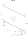
- FIGS. 1 to 17 are diagrams showing examples of a display device according to embodiments of the present disclosure.
- suffixes such as “module” and “unit” may be used to refer to elements or components. Use of such suffixes herein is merely intended to facilitate description of the specification, and the suffixes do not have any special meaning or function.
- a display device 1 may include a display panel 10.
- the display panel 10 may display a screen.
- the display device 1 may include a first long side LS1, a second long side LS2 facing the first long side LS1, a first short side SS1 adjacent to the first long side LS1 and the second long side LS2, and a second short side SS2 facing the first short side SS1.
- first and second long sides LS1 and LS2 are longer than the lengths of the first and second short sides SS1 and SS2, but it may be possible that the lengths of the first and second long sides LS1 and LS2 are approximately the same as the lengths of the first and second short sides SS1 and SS2.
- the direction parallel to the long side LS1, LS2 of the display device 1 may be referred to as a left-right direction or a first direction DR1.
- the direction parallel to the short side SS1, SS2 of the display device 1 may be referred to as an up-down direction or a second direction DR2.
- the direction perpendicular to the long side LS1, LS2 and the short side SS1, SS2 of the display device 1 may be referred to as a front-rear direction or a third direction DR3.
- the direction in which the display panel 10 displays images may be referred to as a forward direction (F, z), and the opposite direction may be referred to as a rearward direction R.
- the side of first long side LS1 may be referred to as an upper side (U, y).
- the side of second long side LS2 may be referred to as a lower side (D, -y).
- the side of first short side SS1 may be referred to as a left side (Le, x).
- the side of second short side SS2 may be referred to as a right side (Ri, -x).
- the first long side LS1, the second long side LS2, the first short side SS1, and the second short side SS2 may be referred to as an edge of the display device 1.
- a point where the first long side LS1, the second long side LS2, the first short side SS1, and the second short side SS2 meet each other may be referred to as a corner.
- first corner C1 a point where the first short side SS1 and the first long side LS1 meet may be referred to as a first corner C1.
- first long side LS1 and the second short side SS2 meet may be referred to as a second corner C2.
- second corner C2 and the second long side LS2 meet may be referred to as a third corner C3.
- a point where the second long side LS2 and the first short side SS1 meet may be referred to as a fourth corner C4.
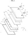
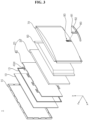
- the display device 1 may include a display panel 10, a front cover 15, a guide panel 13, a backlight unit 20, a frame 60, and a back cover 70.
- the display panel 10 may form the front surface of the display device 1, and may display images.
- the display panel 10 may display an image by outputting red, green, or blue (RGB) for each pixel according to a timing by a plurality of pixels.
- the display panel 10 may be divided into an active area in which an image is displayed and a de-active area in which an image is not displayed.
- the display panel 10 may include a front substrate and a rear substrate that are opposite to each other with a liquid crystal layer interposed therebetween.
- the display panel 10 may be referred to as an LCD panel.
- the display panel 10 is explained as an LCD panel, but an OLED panel may also be applied.
- the front substrate may include a plurality of pixels including red R, green G, and blue B sub-pixels.
- the front substrate may output light corresponding to red, green, or blue color according to a control signal.
- the rear substrate may include switching elements.
- the rear substrate may switch a pixel electrode.
- the pixel electrode may change the molecular arrangement of liquid crystal layer according to a control signal applied from the outside.
- the liquid crystal layer may include liquid crystal molecules. The arrangement of the liquid crystal molecules may change according to a voltage difference generated between the pixel electrode and the common electrode.
- the liquid crystal layer may transmit light provided from the backlight unit 20 to the front substrate or block the light.
- the front cover 15 may surround the circumference of the display panel 10, and cover at least partial area of the front and side surfaces of the display panel 10.
- the front cover 15 may extend along the circumference of the display panel 10.
- the front cover 15 may be divided into a first part located on the front surface of the display panel 10 and a second part located on the side surface.
- the first part and the second part may be provided separately, or may be provided as one body. At least one of the first part and the second part may be omitted.
- the front cover 15 may be referred to as a case top.
- the guide panel 13 may surround the circumference of the display panel 10, and cover at least partial area of the rear and side surfaces of the display panel 10.
- the guide panel 13 may be coupled to the display panel 10, or may support the display panel 10.
- the guide panel 13 may be referred to as a panel guide or side frame.
- the backlight unit 20 may be located in a rearward direction of the display panel 10.
- the backlight unit 20 may include light sources.
- the backlight unit 20 may be coupled to a frame 60 in a forward direction of the frame 60.
- the backlight unit 20 may be driven by a full driving method or a partial driving method such as local dimming or impulsive.
- the backlight unit 20 may include an optical sheet 40 and an optical layer 30. When the display panel 10 is an OLED panel, the backlight unit 20 may be omitted.
- the optical sheet 40 may evenly transmit light from a light source to the display panel 10.
- the optical sheet 40 may include a plurality of layers.
- the optical sheet 40 may include a prism sheet or a diffusion sheet.
- the optical sheet 40 may be a double brightness enhancement film (DBEF).
- DBEF double brightness enhancement film
- a coupling portion 40d of the optical sheet 40 may be coupled to the front cover 15, the frame 60, or the back cover 70.
- the frame 60 may be located in a rear of the backlight unit 20 and may support the components of the display device 1.
- the components such as the backlight unit 20, a Printed Circuit Board (PCB) on which a plurality of electronic devices are located may be coupled to the frame 60.
- the frame 60 may include a metal material such as aluminum alloy.
- the frame 60 may be referred to as a main frame or module cover.
- the back cover 70 may cover the rear of the frame 60.
- the back cover 70 may be coupled to the frame 60 and/or the front cover 15.
- the back cover 70 may be an injection molded product made of resin.
- the back cover 70 may include a metal material.
- a cable (not shown) may be electrically connected to the display panel 10 and a source PCB (not shown).
- the source PCB may be located in the rear of the frame 60.
- the display device 1 may further include a stand 80.
- the stand 80 may be located in the rear of the back cover 70.
- the stand 80 may be coupled to the rear of the frame 60.
- the stand 80 may be coupled to a mounting portion 90 formed in the rear of the back cover 70.
- the mounting portion 90 may be formed in a location adjacent to the lower portion of the rear surface of the back cover 70.
- the stand 80 may be detachably coupled to the frame 60 and/or the back cover 70.
- the stand 80 extends upward from the floor to stand up, and may support the frame 60 so that the frame 60 can be erected from the floor.
- the stand 80 may include a stand body 81 and a stand leg 82.
- the stand leg 82 may be in contact with the floor and support the stand body 81 so that the stand body 81 can be erected.
- the stand body 81 may extend upward from the stand leg 82.
- a plurality of stands 80 may be provided.
- a pair of stands 80 may be located adjacent to both sides of the back cover 70 based on the left-right direction.
- the stand 80 may be provided as a single stand.
- the single stand 80 may be located in the center of the back cover 70 based on the left-right direction.
- the stand body 81 may include a vertical body 810 and an inclined body 820.
- the vertical body 810 may extend in the up-down direction.
- the inclined body 820 may extend while forming an inclination with respect to the vertical body 810.
- the vertical body 810 may include a fastening hole 811, 812, 813, 814.
- the fastening hole 811, 812, 813, 814 may be formed to penetrate the vertical body 810.
- a plurality of fastening holes 811, 812, 813, and 814 may be arranged to be spaced apart from each other in the longitudinal direction of the vertical body 810. For example, there may be four fastening holes 811, 812, 813, and 814.
- the four fastening holes 811, 812, 813, 814 may form two pairs.
- a first fastening hole 811 may be located in the uppermost side of the vertical body 810 among the fastening holes 811, 812, 813, and 814.
- the first fastening hole 811 may include an insertion hole 811a and a hooking portion 811b.
- the insertion hole 811a may have an oval shape.
- the hooking portion 811b may be formed in a portion of the insertion hole 811a, and may be a rib extending to the inside of the insertion hole 811a.
- the hooking portion 811b has an overall U shape, and may fill a portion of the lower side of the insertion hole 811a. Accordingly, a circle hole may be formed in the upper side of the insertion hole 811a, and a slit may be formed in the lower side of the insertion hole 811a. The slit may be connected to a circle hole.
- a second fastening hole 812 may be located in the upper side of the vertical body 810 among the fastening holes 811, 812, 813, and 814, and adjacent to the lower side of the first fastening hole 811.
- the second fastening hole 812 may include an insertion hole 812a, a hooking portion 812b, and a fastening portion 812c.
- the insertion hole 812a may have an oval shape.
- the hooking portion 812b may be formed in a portion of the insertion hole 812a, and may be a rib extending to the inside of the insertion hole 812a.
- the hooking portion 812b has an overall U shape, and may fill a portion of the lower side of the insertion hole 812a.
- a circle hole may be formed in the upper side of the insertion hole 812a, and a slit may be formed in the lower side of the insertion hole 812a.
- the slit may be connected to a circle hole.
- the fastening portion 812c may be located between the circle hole and the slit in the center of the insertion hole 812a, and may be formed by removing both sides of the inner wall of the insertion hole 812a.
- the opening of the insertion hole 812a may be expanded by the fastening portion 812c.
- a third fastening hole 813 may be located in the lower side of the vertical body 810 among the fastening holes 811, 812, 813, and 814, and may be adjacent to the lower side of the second fastening hole 812.
- the third fastening hole 813 may include an insertion hole 813a, a hooking portion 813b, and a fastening portion 813c.
- the insertion hole 813a may have an oval shape.
- the hooking portion 813b may be a rib that is formed in a portion of the insertion hole 813a and extends to the inside of the insertion hole 813a.
- the hooking portion 813b may have an overall U shape, and may fill a portion of the lower side of the insertion hole 813a.
- a circle hole may be formed in the upper side of the insertion hole 813a, and a slit may be formed in the lower side of the insertion hole 813a.
- the slit may be connected to a circle hole.
- the fastening portion 813c may be located between the circle hole and the slit in the center of the insertion hole 813a, and may be formed by removing both sides of the inner wall of the insertion hole 813a.
- the opening of the insertion hole 813a may be expanded by the fastening portion 813c.
- a fourth fastening hole 814 may be located in the lowermost side of the vertical body 810 among the fastening holes 811, 812, 813, and 814.
- the fourth fastening hole 814 may include an insertion hole 814a and a hooking portion 814b.
- the insertion hole 814a may have an oval shape.
- the hooking portion 814b may be a rib that is formed in a portion of the insertion hole 814a, and extends to the inside of the insertion hole 814a.
- the hooking portion 814b may have an overall U shape, and may fill a portion of the lower side of the insertion hole 814a. Accordingly, a circle hole may be formed in the upper side of the insertion hole 814a, and a slit may be formed in the lower side of the insertion hole 814a. The slit may be connected to a circle hole.
- a first distance D1 between the first fastening hole 811 and the second fastening hole 812 may be longer than a second distance D2 between the second fastening hole 812 and the third fastening hole 813.
- the second distance D2 may be shorter than a third distance D3 between the third fastening hole 813 and the fourth fastening hole 814.
- the first distance D1 may be equal to the third distance D3.
- a fixer holder 83 may include a holder body 831, a guide stopper 832, a hook 834, and an end tip 833.
- the holder body 831 may be an open circle or half circle having open one side.
- the fixer holder 83 may have elasticity as a whole.
- the guide stopper 832 may extend from both ends of the holder body 831.
- the guide stoppers 832 may be paired and face each other.
- the guide stopper 832 may extend from one end of the holder body 831 in the radial direction of the half circle.
- a pair of guide stoppers 832 may extend away from each other in the radial direction of the holder body 831.
- the end tips 833 may be a pair. Each of the pair of end tips 833 may be connected to each of the pair of guide stoppers 832.
- the end tip 833 may have a curved shape.
- the holder body 831, the guide stopper 832, and the end tip 833 may have an overall omega shape.
- the hook 834 may extend from the guide stopper 832 and/or the holder body 831 in a direction parallel to the direction of central axis of the half circle of the holder body 831.
- the hooks 834 may be a pair, and each of the pair of hooks 834 may extend from each of the pair of guide stoppers 832 and/or the holder body 831.
- the fixer holder 83 may be inserted into the second fastening hole 812 and/or the third fastening hole 813.
- the holder body 831 may be inserted into the lower side of the insertion hole 812a, 813a of the fastening hole 812, 813, and may be supported by the hooking portion 812b, 813b.
- the outer diameter of the holder body 831 may correspond to the diameter of the inner wall of the lower side of the insertion hole 812a, 813a.
- the inner wall of the lower side of the insertion hole 812a, 813a may be supported by or in contact with the outer wall of the holder body 831.
- the hook 834 may be hooked to the fastening portion 812c, 813c of the fastening hole 812, 813 to fix the fixer holder 83 to the fastening hole 812, 813.
- the end tip 833 may be supported by the outer wall of the circle hole of the upper side of the insertion hole 812a, 813a. The end tip 833 may restrict the diameter of the holder body 831 from being reduced.
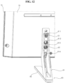
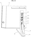
- the mounting portion 90 may include a fixer 91, 92. There may be a plurality of fixers 91 and 92. A plurality of fixers 91 and 92 may be arranged in the up-down direction.
- a first fixer 91 may be fixed to the frame 60 (see FIGS. 2 and 3 ) and/or the back cover 70, and may protrude from the rear surface of the back cover 70.
- a second fixer 92 may be adjacent to the first fixer 91 in the lower side of the first fixer 91.
- the second fixer 92 may be fixed to the frame 60 and/or the back cover 70, and may protrude from the rear surface of the back cover 70.
- the distance between the first fixer 91 and the second fixer 92 may correspond to the distance between the first fastening hole 811 and the third fastening hole 813 or the distance between the second fastening hole 812 and the fourth fastening hole 814.
- the second fixer 92 may be inserted into the third fastening hole 813.
- the second fixer 92 may be inserted into the fourth fastening hole 814.
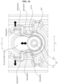
- the fixer 91 may include a fixed shaft 91b and a head 91a.
- the head 91a may be formed in the upper end of the fixed shaft 91b.
- the head 91a may have a disk shape.
- the diameter of the head 91a may be larger than the diameter of the fixed shaft 91b.
- the head 91a of the fixer 91 may be inserted into the fastening hole 812, 813 through a circle hole of the insertion hole 812a, 813a. After the head 91a is inserted, the fixer 91 may move to the slit of the insertion hole 812a, 813a. As the fixer 91 moves, the lower side of the head 91a of the fixer 91 may be supported by the hooking portion 812b, 813b (see FIG. 9 ) of the fastening hole 812, 813. As the fixer 91 moves, the head 91a of the fixer 91 may rub along the guide stopper 832 of the fixer holder 831.
- a gap of the guide stopper 832 may widen or narrow.
- the position of the fixer 91 may be fixed by the holder body 831 and the guide stopper 832 of the fixer holder 83.
- the gap of the guide stopper 832 may widen.
- the force with which the fixer holder 83 tightens the fixer 91 may correspond to the weight of the stand 80.
- a user may insert the stand 80 into the fixer 91 or remove the stand 80 from the fixer 91.
- a user may easily adjust the height of the display device by adjusting the position where the stand 80 is inserted into the fixer 91.
- the fixer holder 84 may include a first coupling 841, a second coupling 843, and a bridge 842.
- the fixer holder 84 may have elasticity as a whole.
- the first coupling 841 may include a first circle 841a and a second circle 841b.
- the first circle 841a may be an open circle having an open portion or a half circle.
- the second circle 841b may be an open circle having an open portion or a half circle, and may be connected to the first circle 841a.
- a narrow neck 841c may be formed between the first circle 841a and the second circle 841b.
- a tapered rounding part 841d may be formed in the inner edge of the first circle 841a.
- the second coupling 843 may include a first circle 843a and a second circle 843b.
- the first circle 843a may be an open circle having an open portion or a half circle.
- the second circle 843b may be an open circle having an open portion or a half circle, and may be connected to the first circle 843a.
- a narrow neck 843c may be formed between the first circle 843a and the second circle 843b.
- a tapered rounding part 843d may be formed in the inner edge of the second circle 843b.
- the bridge 842 may connect the second circle 841b of the first coupling 841 and the second circle 843b of the second coupling 843.
- the bridge 842 may be a tangent line of the second circles 841b and 843b, and may be plural.
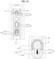
- the vertical body 810 may include fastening holes 811, 812, 813, and 814.
- the fastening hole 811, 812, 813, 814 may be formed to penetrate the vertical body 810.
- a plurality of fastening holes 811, 812, 813, and 814 may be arranged to be spaced apart from each other in the longitudinal direction of the vertical body 810. For example, there may be four fastening holes 811, 812, 813, and 814.
- the four fastening holes 811, 812, 813, and 814 may form two pairs.
- the first fastening hole 811 may be located in the uppermost side of the vertical body 810 among the fastening holes 811, 812, 813, and 814.
- the first fastening hole 811 may include the insertion hole 811a and the hooking portion 811b.
- the insertion hole 811a may have an oval shape.
- the hooking portion 811b may be formed in a portion of the insertion hole 811a, and may be a rib that extends to the inner side of the insertion hole 811a.
- the hooking portion 811b has an overall U shape, and may fill a portion of the lower side of the insertion hole 811a. Accordingly, a circle hole may be formed in the upper side of the insertion hole 811a, and a slit may be formed in the lower side of the insertion hole 811a. The slit may be connected to the circle hole.
- the second fastening hole 812 may be located in the upper side of the vertical body 810 among the fastening holes 811, 812, 813, and 814, and adjacent to the lower side of the first fastening hole 811.
- the second fastening hole 812 may include the insertion hole 812a and the hooking portion 812b.
- the insertion hole 812a may have an oval shape.
- the hooking portion 812b may be formed in a portion of the insertion hole 812a, and may be a rib that extends to the inside of the insertion hole 812a.
- the hooking portion 812b has an overall U shape, and may fill a portion of the lower side of the insertion hole 812a. Accordingly, a circle hole may be formed in the upper side of the insertion hole 812a, and a slit may be formed in the lower side of the insertion hole 812a. The slit may be connected to the circle hole.
- the third fastening hole 813 may be located in the lower side of the vertical body 810 among the fastening holes 811, 812, 813, and 814, and may be adjacent to the lower side of the second fastening hole 812.
- the third fastening hole 813 may include the insertion hole 813a and the hooking portion 813b.
- the insertion hole 813a may have an oval shape.
- the hooking portion 813b may be a rib that is formed in a portion of the insertion hole 813a and extends to the inner side of the insertion hole 813a.
- the hooking portion 813b has an overall U shape, and may fill a portion of the lower side of the insertion hole 813a.
- a circle hole may be formed in the upper side of the insertion hole 813a, and a slit may be formed in the lower side of the insertion hole 813a.
- the slit may be connected to the circle hole.
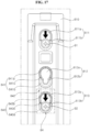
- the fixer holder 84 may be coupled around the second fastening hole 812 and the third fastening hole 813.
- the first coupling 841 may be aligned with the second fastening hole 812
- the second coupling 843 may be aligned with the third fastening hole 813.
- the fixer holder 84 may be disposed around the second fastening hole 812 and the third fastening hole 813.
- the first circle 841a of the first coupling 841 may be aligned with or correspond to the insertion hole 812a of the second fastening hole 812, and the second circle 843b of the second coupling 843 may be aligned with or correspond to the insertion hole 813a of the third fastening hole 813.
- the first fixer 91 may be inserted into the insertion hole 811a of the first fastening hole 811, the second fixer 92 may be inserted into the insertion hole 813a of the third fastening hole 813, and the first fixer 91 and the second fixer 92 may pass through the narrow neck 841c, 843c while moving downward.
- the narrow necks 841c and 843c may prevent the first fixer 91 and/or the second fixer 92 from being separated from the hooking portion 811b, 913b.
- the first fixer 91 and/or the second fixer 92 may escape from the hooking portion 811b, 813b by external force and located in the insertion holes 811a, 813a.
- the display device includes: a display panel; a frame to which the display panel is coupled, and is located in a rear of the display panel; a fixer which is coupled to the frame, and protrudes toward a rear of the frame; and a stand which is coupled to the fixer, wherein the stand includes: a stand body in which a plurality of fastening holes that are sequentially arranged in an up-down direction are formed; a fixer holder which is inserted into at least one of the plurality of fastening holes; and a stand leg coupled to a bottom of the stand body, wherein the fixer is inserted into the fixer holder.
- Each of the plurality of fastening holes includes: an insertion hole which is formed as a long hole extending in an up-down direction where the fastening hole is disposed; and a hooking portion which is formed in a lower side of the insertion hole, extends to an inner side of the insertion hole to form the insertion hole as a circle hole, and forms a slit connected to the circle hole.
- At least one of the plurality of fastening holes further includes a fastening portion which is located between the circle hole and the slit, and expands the fastening hole in a left-right direction.
- the fixer holder includes: a holder body which is supported by the hooking portion, and has an open ring shape having one side open; a pair of guide stoppers which extend from both ends of the holder body, extend toward the circle hole, and widen from the hooking portion toward the circle hole; and an end tip which extends from both ends of the pair of guide stoppers, and supported by an outer wall of the circle hole.
- the fixer holder further includes a hook that extends from the guide stopper or the holder body, and is hooked to a fastening portion of the fastening hole.
- the fixer includes: a fixed shaft fixed to the frame; and a head formed in a distal end of the fixed shaft, wherein a diameter of the head is larger than a diameter of the fixed shaft, and corresponds to a diameter of the circle hole.
- the diameter of the head corresponds to an inner diameter of the holder body.
- a width of the slit corresponds to a diameter of the fixed axis of the fixer.
- the pair of guide stoppers widen when the head of the fixer moves from the circle hole to the slit, and the pair of guide stoppers are recovered when the head of the fixer is located in the slit.
- a distance between a pair of narrow necks formed by the pair of guide stoppers and the holder body is smaller than the head of the fixer.
- a display device that can easily combine or separate a stand can be provided.
- a display device that can stably couple a stand can be provided.
- a display device that can be coupled with a stand without fastening a screw may be provided.
- a display device that can conveniently adjust a height can be provided.
- a configuration "A” described in one embodiment of the invention and the drawings and a configuration "B” described in another embodiment of the invention and the drawings may be combined with each other. Namely, although the combination between the configurations is not directly described, the combination is possible except in the case where it is described that the combination is impossible
Landscapes
- Engineering & Computer Science (AREA)
- General Engineering & Computer Science (AREA)
- Physics & Mathematics (AREA)
- Mechanical Engineering (AREA)
- Theoretical Computer Science (AREA)
- Nonlinear Science (AREA)
- General Physics & Mathematics (AREA)
- Computer Hardware Design (AREA)
- Mathematical Physics (AREA)
- Chemical & Material Sciences (AREA)
- Crystallography & Structural Chemistry (AREA)
- Human Computer Interaction (AREA)
- Optics & Photonics (AREA)
- Devices For Indicating Variable Information By Combining Individual Elements (AREA)
Abstract
Disclosed is a display device. The display device includes: a display panel; a frame to which the display panel is coupled, and is located in a rear of the display panel; a fixer which is coupled to the frame, and protrudes toward a rear of the frame; and a stand which is coupled to the fixer, wherein the stand includes: a stand body in which a plurality of fastening holes that are sequentially arranged in an up-down direction are formed; a fixer holder which is inserted into at least one of the plurality of fastening holes; and a stand leg coupled to a bottom of the stand body, wherein the fixer is inserted into the fixer holder.
Description
- This disclosure relates to a display device.
- As the information society develops, the demand for display devices is also increasing in various forms. In response to this, in recent years, various display devices such as Liquid Crystal Display Device (LCD), Plasma Display Panel (PDP), Electroluminescent Display (ELD), Vacuum Fluorescent Display (VFD), and Organic Light Emitting Diode (OLED) have been researched and used.
- The display device may include a panel and various sheets for displaying images, and may include structures such as various guides, frames, and covers to arrange, support, couple, and protect the components of the display device. The display device may further include a stand to support a display panel and position the display panel upward from a floor.
- When moving a display device, it is necessary to separate or reassemble the stand and components of the display device, and also necessary to adjust the height of the display panel according to user's needs. Recently, much research has been conducted to solve these problems.
- The disclosure has been made in view of the above problems, and may provide a display device that can easily couple or separate a stand.
- The disclosure may further provide a display device that can stably couple a stand.
- The disclosure may further provide a display device that can be coupled with a stand without fastening a screw.
- The disclosure may further provide a display device that can conveniently adjust a height.
- In accordance with an aspect of the present disclosure, a display device includes: a display panel; a frame to which the display panel is coupled, and is located in a rear of the display panel; a fixer which is coupled to the frame, and protrudes toward a rear of the frame; and a stand which is coupled to the fixer, wherein the stand includes: a stand body in which a plurality of fastening holes that are sequentially arranged in an up-down direction are formed; a fixer holder which is inserted into at least one of the plurality of fastening holes; and a stand leg coupled to a bottom of the stand body, wherein the fixer is inserted into the fixer holder.
- The above and other objects, features and advantages of the present disclosure will be more apparent from the following detailed description in conjunction with the accompanying drawings, in which:
FIGS. 1 to 17 are diagrams showing examples of a display device according to embodiments of the present disclosure. - Description will now be given in detail according to exemplary embodiments disclosed herein, with reference to the accompanying drawings. For the sake of brief description with reference to the drawings, the same or equivalent components may be denoted by the same reference numbers, and description thereof will not be repeated.
- In general, suffixes such as "module" and "unit" may be used to refer to elements or components. Use of such suffixes herein is merely intended to facilitate description of the specification, and the suffixes do not have any special meaning or function.
- In the present disclosure, that which is well known to one of ordinary skill in the relevant art has generally been omitted for the sake of brevity. The accompanying drawings are used to assist in easy understanding of various technical features and it should be understood that the embodiments presented herein are not limited by the accompanying drawings. As such, the present disclosure should be construed to extend to any alterations, equivalents and substitutes in addition to those which are particularly set out in the accompanying drawings.
- It will be understood that although the terms first, second, etc. may be used herein to describe various elements, these elements should not be limited by these terms. These terms are only used to distinguish one element from another.
- It will be understood that when an element is referred to as being "connected with" another element, there may be intervening elements present. In contrast, it will be understood that when an element is referred to as being "directly connected with" another element, there are no intervening elements present.
- A singular representation may include a plural representation unless context clearly indicates otherwise.
- In the present application, it should be understood that the terms "comprises, includes," "has," etc. specify the presence of features, numbers, steps, operations, elements, components, or combinations thereof described in the specification, but do not preclude the presence or addition of one or more other features, numbers, steps, operations, elements, components, or combinations thereof.
- The direction indications of up(U), down(D), left (Le), right(Ri), front(F), and rear (R) shown in the drawings are only for convenience of explanation, and the technical idea disclosed in this specification is not limited.
- Referring to
FIG. 1 , adisplay device 1 may include adisplay panel 10. Thedisplay panel 10 may display a screen. - The
display device 1 may include a first long side LS1, a second long side LS2 facing the first long side LS1, a first short side SS1 adjacent to the first long side LS1 and the second long side LS2, and a second short side SS2 facing the first short side SS1. - For convenience of explanation, it is illustrated that the lengths of the first and second long sides LS1 and LS2 are longer than the lengths of the first and second short sides SS1 and SS2, but it may be possible that the lengths of the first and second long sides LS1 and LS2 are approximately the same as the lengths of the first and second short sides SS1 and SS2.
- The direction parallel to the long side LS1, LS2 of the
display device 1 may be referred to as a left-right direction or a first direction DR1. The direction parallel to the short side SS1, SS2 of thedisplay device 1 may be referred to as an up-down direction or a second direction DR2. The direction perpendicular to the long side LS1, LS2 and the short side SS1, SS2 of thedisplay device 1 may be referred to as a front-rear direction or a third direction DR3. - The direction in which the
display panel 10 displays images may be referred to as a forward direction (F, z), and the opposite direction may be referred to as a rearward direction R. The side of first long side LS1 may be referred to as an upper side (U, y). The side of second long side LS2 may be referred to as a lower side (D, -y). The side of first short side SS1 may be referred to as a left side (Le, x). The side of second short side SS2 may be referred to as a right side (Ri, -x). - The first long side LS1, the second long side LS2, the first short side SS1, and the second short side SS2 may be referred to as an edge of the
display device 1. In addition, a point where the first long side LS1, the second long side LS2, the first short side SS1, and the second short side SS2 meet each other may be referred to as a corner. - For example, a point where the first short side SS1 and the first long side LS1 meet may be referred to as a first corner C1. A point where the first long side LS1 and the second short side SS2 meet may be referred to as a second corner C2. A point where the second short side SS2 and the second long side LS2 meet may be referred to as a third corner C3. A point where the second long side LS2 and the first short side SS1 meet may be referred to as a fourth corner C4.
- Referring to
FIGS. 2 and3 , thedisplay device 1 may include adisplay panel 10, afront cover 15, aguide panel 13, abacklight unit 20, aframe 60, and aback cover 70. - The
display panel 10 may form the front surface of thedisplay device 1, and may display images. Thedisplay panel 10 may display an image by outputting red, green, or blue (RGB) for each pixel according to a timing by a plurality of pixels. Thedisplay panel 10 may be divided into an active area in which an image is displayed and a de-active area in which an image is not displayed. Thedisplay panel 10 may include a front substrate and a rear substrate that are opposite to each other with a liquid crystal layer interposed therebetween. Thedisplay panel 10 may be referred to as an LCD panel. Thedisplay panel 10 is explained as an LCD panel, but an OLED panel may also be applied. - The front substrate may include a plurality of pixels including red R, green G, and blue B sub-pixels. The front substrate may output light corresponding to red, green, or blue color according to a control signal.
- The rear substrate may include switching elements. The rear substrate may switch a pixel electrode. For example, the pixel electrode may change the molecular arrangement of liquid crystal layer according to a control signal applied from the outside. The liquid crystal layer may include liquid crystal molecules. The arrangement of the liquid crystal molecules may change according to a voltage difference generated between the pixel electrode and the common electrode. The liquid crystal layer may transmit light provided from the
backlight unit 20 to the front substrate or block the light. - The
front cover 15 may surround the circumference of thedisplay panel 10, and cover at least partial area of the front and side surfaces of thedisplay panel 10. Thefront cover 15 may extend along the circumference of thedisplay panel 10. Thefront cover 15 may be divided into a first part located on the front surface of thedisplay panel 10 and a second part located on the side surface. The first part and the second part may be provided separately, or may be provided as one body. At least one of the first part and the second part may be omitted. Thefront cover 15 may be referred to as a case top. - The
guide panel 13 may surround the circumference of thedisplay panel 10, and cover at least partial area of the rear and side surfaces of thedisplay panel 10. Theguide panel 13 may be coupled to thedisplay panel 10, or may support thedisplay panel 10. Theguide panel 13 may be referred to as a panel guide or side frame. - The
backlight unit 20 may be located in a rearward direction of thedisplay panel 10. Thebacklight unit 20 may include light sources. Thebacklight unit 20 may be coupled to aframe 60 in a forward direction of theframe 60. Thebacklight unit 20 may be driven by a full driving method or a partial driving method such as local dimming or impulsive. Thebacklight unit 20 may include anoptical sheet 40 and anoptical layer 30. When thedisplay panel 10 is an OLED panel, thebacklight unit 20 may be omitted. - The
optical sheet 40 may evenly transmit light from a light source to thedisplay panel 10. Theoptical sheet 40 may include a plurality of layers. For example, theoptical sheet 40 may include a prism sheet or a diffusion sheet. For example, theoptical sheet 40 may be a double brightness enhancement film (DBEF). Meanwhile, acoupling portion 40d of theoptical sheet 40 may be coupled to thefront cover 15, theframe 60, or theback cover 70. - The
frame 60 may be located in a rear of thebacklight unit 20 and may support the components of thedisplay device 1. For example, the components such as thebacklight unit 20, a Printed Circuit Board (PCB) on which a plurality of electronic devices are located may be coupled to theframe 60. Theframe 60 may include a metal material such as aluminum alloy. Theframe 60 may be referred to as a main frame or module cover. - The
back cover 70 may cover the rear of theframe 60. Theback cover 70 may be coupled to theframe 60 and/or thefront cover 15. For example, theback cover 70 may be an injection molded product made of resin. For another example, theback cover 70 may include a metal material. - Meanwhile, a cable (not shown) may be electrically connected to the
display panel 10 and a source PCB (not shown). The source PCB may be located in the rear of theframe 60. - Meanwhile, the
display device 1 may further include astand 80. Thestand 80 may be located in the rear of theback cover 70. Thestand 80 may be coupled to the rear of theframe 60. Thestand 80 may be coupled to a mountingportion 90 formed in the rear of theback cover 70. The mountingportion 90 may be formed in a location adjacent to the lower portion of the rear surface of theback cover 70. Thestand 80 may be detachably coupled to theframe 60 and/or theback cover 70. - The
stand 80 extends upward from the floor to stand up, and may support theframe 60 so that theframe 60 can be erected from the floor. Thestand 80 may include astand body 81 and astand leg 82. Thestand leg 82 may be in contact with the floor and support thestand body 81 so that thestand body 81 can be erected. Thestand body 81 may extend upward from thestand leg 82. - Referring to
FIG. 2 , a plurality ofstands 80 may be provided. For example, a pair ofstands 80 may be located adjacent to both sides of theback cover 70 based on the left-right direction. Referring toFIG. 3 , thestand 80 may be provided as a single stand. Thesingle stand 80 may be located in the center of theback cover 70 based on the left-right direction. - Referring to
FIGS. 4 and5 , thestand body 81 may include avertical body 810 and aninclined body 820. Thevertical body 810 may extend in the up-down direction. Theinclined body 820 may extend while forming an inclination with respect to thevertical body 810. - The
vertical body 810 may include afastening hole fastening hole vertical body 810. A plurality offastening holes vertical body 810. For example, there may be fourfastening holes fastening holes - A
first fastening hole 811 may be located in the uppermost side of thevertical body 810 among the fastening holes 811, 812, 813, and 814. Thefirst fastening hole 811 may include aninsertion hole 811a and a hookingportion 811b. For example, theinsertion hole 811a may have an oval shape. The hookingportion 811b may be formed in a portion of theinsertion hole 811a, and may be a rib extending to the inside of theinsertion hole 811a. For example, the hookingportion 811b has an overall U shape, and may fill a portion of the lower side of theinsertion hole 811a. Accordingly, a circle hole may be formed in the upper side of theinsertion hole 811a, and a slit may be formed in the lower side of theinsertion hole 811a. The slit may be connected to a circle hole. - A
second fastening hole 812 may be located in the upper side of thevertical body 810 among the fastening holes 811, 812, 813, and 814, and adjacent to the lower side of thefirst fastening hole 811. Thesecond fastening hole 812 may include aninsertion hole 812a, a hookingportion 812b, and afastening portion 812c. For example, theinsertion hole 812a may have an oval shape. The hookingportion 812b may be formed in a portion of theinsertion hole 812a, and may be a rib extending to the inside of theinsertion hole 812a. For example, the hookingportion 812b has an overall U shape, and may fill a portion of the lower side of theinsertion hole 812a. Accordingly, a circle hole may be formed in the upper side of theinsertion hole 812a, and a slit may be formed in the lower side of theinsertion hole 812a. The slit may be connected to a circle hole. Thefastening portion 812c may be located between the circle hole and the slit in the center of theinsertion hole 812a, and may be formed by removing both sides of the inner wall of theinsertion hole 812a. The opening of theinsertion hole 812a may be expanded by thefastening portion 812c. - A
third fastening hole 813 may be located in the lower side of thevertical body 810 among the fastening holes 811, 812, 813, and 814, and may be adjacent to the lower side of thesecond fastening hole 812. Thethird fastening hole 813 may include aninsertion hole 813a, a hookingportion 813b, and afastening portion 813c. For example, theinsertion hole 813a may have an oval shape. The hookingportion 813b may be a rib that is formed in a portion of theinsertion hole 813a and extends to the inside of theinsertion hole 813a. For example, the hookingportion 813b may have an overall U shape, and may fill a portion of the lower side of theinsertion hole 813a. Accordingly, a circle hole may be formed in the upper side of theinsertion hole 813a, and a slit may be formed in the lower side of theinsertion hole 813a. The slit may be connected to a circle hole. Thefastening portion 813c may be located between the circle hole and the slit in the center of theinsertion hole 813a, and may be formed by removing both sides of the inner wall of theinsertion hole 813a. The opening of theinsertion hole 813a may be expanded by thefastening portion 813c. - A
fourth fastening hole 814 may be located in the lowermost side of thevertical body 810 among the fastening holes 811, 812, 813, and 814. Thefourth fastening hole 814 may include aninsertion hole 814a and a hookingportion 814b. For example, theinsertion hole 814a may have an oval shape. The hookingportion 814b may be a rib that is formed in a portion of theinsertion hole 814a, and extends to the inside of theinsertion hole 814a. For example, the hookingportion 814b may have an overall U shape, and may fill a portion of the lower side of theinsertion hole 814a. Accordingly, a circle hole may be formed in the upper side of theinsertion hole 814a, and a slit may be formed in the lower side of theinsertion hole 814a. The slit may be connected to a circle hole. - A first distance D1 between the
first fastening hole 811 and thesecond fastening hole 812 may be longer than a second distance D2 between thesecond fastening hole 812 and thethird fastening hole 813. The second distance D2 may be shorter than a third distance D3 between thethird fastening hole 813 and thefourth fastening hole 814. The first distance D1 may be equal to the third distance D3. - Referring to
FIGS. 6 and7 , afixer holder 83 may include aholder body 831, aguide stopper 832, ahook 834, and anend tip 833. Theholder body 831 may be an open circle or half circle having open one side. Thefixer holder 83 may have elasticity as a whole. - The
guide stopper 832 may extend from both ends of theholder body 831. Theguide stoppers 832 may be paired and face each other. Theguide stopper 832 may extend from one end of theholder body 831 in the radial direction of the half circle. A pair ofguide stoppers 832 may extend away from each other in the radial direction of theholder body 831. - The
end tips 833 may be a pair. Each of the pair ofend tips 833 may be connected to each of the pair ofguide stoppers 832. Theend tip 833 may have a curved shape. Theholder body 831, theguide stopper 832, and theend tip 833 may have an overall omega shape. - The
hook 834 may extend from theguide stopper 832 and/or theholder body 831 in a direction parallel to the direction of central axis of the half circle of theholder body 831. Thehooks 834 may be a pair, and each of the pair ofhooks 834 may extend from each of the pair ofguide stoppers 832 and/or theholder body 831. - Referring to
FIGS. 8 and9 , thefixer holder 83 may be inserted into thesecond fastening hole 812 and/or thethird fastening hole 813. Theholder body 831 may be inserted into the lower side of theinsertion hole fastening hole portion - The outer diameter of the
holder body 831 may correspond to the diameter of the inner wall of the lower side of theinsertion hole insertion hole holder body 831. - The
hook 834 may be hooked to thefastening portion fastening hole fixer holder 83 to thefastening hole end tip 833 may be supported by the outer wall of the circle hole of the upper side of theinsertion hole end tip 833 may restrict the diameter of theholder body 831 from being reduced. - Referring to
FIGS. 10 to 13 , the mountingportion 90 may include afixer fixers fixers first fixer 91 may be fixed to the frame 60 (seeFIGS. 2 and3 ) and/or theback cover 70, and may protrude from the rear surface of theback cover 70. Asecond fixer 92 may be adjacent to thefirst fixer 91 in the lower side of thefirst fixer 91. Thesecond fixer 92 may be fixed to theframe 60 and/or theback cover 70, and may protrude from the rear surface of theback cover 70. - The distance between the
first fixer 91 and thesecond fixer 92 may correspond to the distance between thefirst fastening hole 811 and thethird fastening hole 813 or the distance between thesecond fastening hole 812 and thefourth fastening hole 814. When thefirst fixer 91 is inserted into thefirst fastening hole 811, thesecond fixer 92 may be inserted into thethird fastening hole 813. When thefirst fixer 91 is inserted into thesecond fastening hole 812, thesecond fixer 92 may be inserted into thefourth fastening hole 814. - Referring to
FIG. 14 , thefixer 91 may include a fixedshaft 91b and ahead 91a. Thehead 91a may be formed in the upper end of the fixedshaft 91b. Thehead 91a may have a disk shape. The diameter of thehead 91a may be larger than the diameter of the fixedshaft 91b. - The
head 91a of thefixer 91 may be inserted into thefastening hole insertion hole head 91a is inserted, thefixer 91 may move to the slit of theinsertion hole fixer 91 moves, the lower side of thehead 91a of thefixer 91 may be supported by the hookingportion FIG. 9 ) of thefastening hole fixer 91 moves, thehead 91a of thefixer 91 may rub along theguide stopper 832 of thefixer holder 831. As thehead 91a of thefixer 91 is inserted into theholder body 831, a gap of theguide stopper 832 may widen or narrow. The position of thefixer 91 may be fixed by theholder body 831 and theguide stopper 832 of thefixer holder 83. - When the
fixer 91 comes out of theholder body 831 of thefixer holder 83, the gap of theguide stopper 832 may widen. The force with which thefixer holder 83 tightens thefixer 91 may correspond to the weight of thestand 80. A user may insert thestand 80 into thefixer 91 or remove thestand 80 from thefixer 91. In addition, a user may easily adjust the height of the display device by adjusting the position where thestand 80 is inserted into thefixer 91. - Referring to
FIG. 15 , thefixer holder 84 may include afirst coupling 841, asecond coupling 843, and abridge 842. Thefixer holder 84 may have elasticity as a whole. Thefirst coupling 841 may include afirst circle 841a and asecond circle 841b. Thefirst circle 841a may be an open circle having an open portion or a half circle. Thesecond circle 841b may be an open circle having an open portion or a half circle, and may be connected to thefirst circle 841a. Anarrow neck 841c may be formed between thefirst circle 841a and thesecond circle 841b. A tapered roundingpart 841d may be formed in the inner edge of thefirst circle 841a. - The
second coupling 843 may include afirst circle 843a and asecond circle 843b. Thefirst circle 843a may be an open circle having an open portion or a half circle. Thesecond circle 843b may be an open circle having an open portion or a half circle, and may be connected to thefirst circle 843a. Anarrow neck 843c may be formed between thefirst circle 843a and thesecond circle 843b. A tapered roundingpart 843d may be formed in the inner edge of thesecond circle 843b. - The
bridge 842 may connect thesecond circle 841b of thefirst coupling 841 and thesecond circle 843b of thesecond coupling 843. Thebridge 842 may be a tangent line of thesecond circles - Referring to
FIGS. 16 and17 , thevertical body 810 may includefastening holes fastening hole vertical body 810. A plurality offastening holes vertical body 810. For example, there may be fourfastening holes fastening holes - The
first fastening hole 811 may be located in the uppermost side of thevertical body 810 among the fastening holes 811, 812, 813, and 814. Thefirst fastening hole 811 may include theinsertion hole 811a and the hookingportion 811b. For example, theinsertion hole 811a may have an oval shape. The hookingportion 811b may be formed in a portion of theinsertion hole 811a, and may be a rib that extends to the inner side of theinsertion hole 811a. For example, the hookingportion 811b has an overall U shape, and may fill a portion of the lower side of theinsertion hole 811a. Accordingly, a circle hole may be formed in the upper side of theinsertion hole 811a, and a slit may be formed in the lower side of theinsertion hole 811a. The slit may be connected to the circle hole. - The
second fastening hole 812 may be located in the upper side of thevertical body 810 among the fastening holes 811, 812, 813, and 814, and adjacent to the lower side of thefirst fastening hole 811. Thesecond fastening hole 812 may include theinsertion hole 812a and the hookingportion 812b. For example, theinsertion hole 812a may have an oval shape. The hookingportion 812b may be formed in a portion of theinsertion hole 812a, and may be a rib that extends to the inside of theinsertion hole 812a. For example, the hookingportion 812b has an overall U shape, and may fill a portion of the lower side of theinsertion hole 812a. Accordingly, a circle hole may be formed in the upper side of theinsertion hole 812a, and a slit may be formed in the lower side of theinsertion hole 812a. The slit may be connected to the circle hole. - The
third fastening hole 813 may be located in the lower side of thevertical body 810 among the fastening holes 811, 812, 813, and 814, and may be adjacent to the lower side of thesecond fastening hole 812. Thethird fastening hole 813 may include theinsertion hole 813a and the hookingportion 813b. For example, theinsertion hole 813a may have an oval shape. The hookingportion 813b may be a rib that is formed in a portion of theinsertion hole 813a and extends to the inner side of theinsertion hole 813a. For example, the hookingportion 813b has an overall U shape, and may fill a portion of the lower side of theinsertion hole 813a. Accordingly, a circle hole may be formed in the upper side of theinsertion hole 813a, and a slit may be formed in the lower side of theinsertion hole 813a. The slit may be connected to the circle hole. The description of the above-describedfastening holes fourth fastening hole 814. - The
fixer holder 84 may be coupled around thesecond fastening hole 812 and thethird fastening hole 813. Thefirst coupling 841 may be aligned with thesecond fastening hole 812, and thesecond coupling 843 may be aligned with thethird fastening hole 813. Thefixer holder 84 may be disposed around thesecond fastening hole 812 and thethird fastening hole 813. - The
first circle 841a of thefirst coupling 841 may be aligned with or correspond to theinsertion hole 812a of thesecond fastening hole 812, and thesecond circle 843b of thesecond coupling 843 may be aligned with or correspond to theinsertion hole 813a of thethird fastening hole 813. - The
first fixer 91 may be inserted into theinsertion hole 811a of thefirst fastening hole 811, thesecond fixer 92 may be inserted into theinsertion hole 813a of thethird fastening hole 813, and thefirst fixer 91 and thesecond fixer 92 may pass through thenarrow neck first fixer 91 and/or thesecond fixer 92 are located in the hookingportion narrow necks first fixer 91 and/or thesecond fixer 92 from being separated from the hookingportion 811b, 913b. - When a user moves the stand 80 (see
FIGS. 12 and13 ), thefirst fixer 91 and/or thesecond fixer 92 may escape from the hookingportion insertion holes - Referring to
FIGS. 1 to 17 , the display device includes: a display panel; a frame to which the display panel is coupled, and is located in a rear of the display panel; a fixer which is coupled to the frame, and protrudes toward a rear of the frame; and a stand which is coupled to the fixer, wherein the stand includes: a stand body in which a plurality of fastening holes that are sequentially arranged in an up-down direction are formed; a fixer holder which is inserted into at least one of the plurality of fastening holes; and a stand leg coupled to a bottom of the stand body, wherein the fixer is inserted into the fixer holder. - Each of the plurality of fastening holes includes: an insertion hole which is formed as a long hole extending in an up-down direction where the fastening hole is disposed; and a hooking portion which is formed in a lower side of the insertion hole, extends to an inner side of the insertion hole to form the insertion hole as a circle hole, and forms a slit connected to the circle hole.
- At least one of the plurality of fastening holes further includes a fastening portion which is located between the circle hole and the slit, and expands the fastening hole in a left-right direction.
- The fixer holder includes: a holder body which is supported by the hooking portion, and has an open ring shape having one side open; a pair of guide stoppers which extend from both ends of the holder body, extend toward the circle hole, and widen from the hooking portion toward the circle hole; and an end tip which extends from both ends of the pair of guide stoppers, and supported by an outer wall of the circle hole.
- The fixer holder further includes a hook that extends from the guide stopper or the holder body, and is hooked to a fastening portion of the fastening hole.
- The fixer includes: a fixed shaft fixed to the frame; and a head formed in a distal end of the fixed shaft, wherein a diameter of the head is larger than a diameter of the fixed shaft, and corresponds to a diameter of the circle hole.
- The diameter of the head corresponds to an inner diameter of the holder body.
- A width of the slit corresponds to a diameter of the fixed axis of the fixer.
- In the fixer holder, the pair of guide stoppers widen when the head of the fixer moves from the circle hole to the slit, and the pair of guide stoppers are recovered when the head of the fixer is located in the slit.
- A distance between a pair of narrow necks formed by the pair of guide stoppers and the holder body is smaller than the head of the fixer.
- The effects of the display device according to the present disclosure will be described as follows.
- According to at least one of the embodiments of the present disclosure, a display device that can easily combine or separate a stand can be provided.
- According to at least one of the embodiments of the present disclosure, a display device that can stably couple a stand can be provided.
- According to at least one of the embodiments of the present disclosure, a display device that can be coupled with a stand without fastening a screw may be provided.
- According to at least one of the embodiments of the present disclosure, a display device that can conveniently adjust a height can be provided.
- Certain embodiments or other embodiments of the invention described above are not mutually exclusive or distinct from each other. Any or all elements of the embodiments of the invention described above may be combined or combined with each other in configuration or function.
- For example, a configuration "A" described in one embodiment of the invention and the drawings and a configuration "B" described in another embodiment of the invention and the drawings may be combined with each other. Namely, although the combination between the configurations is not directly described, the combination is possible except in the case where it is described that the combination is impossible
- Although embodiments have been described with reference to a number of illustrative embodiments thereof, it should be understood that numerous other modifications and embodiments can be devised by those skilled in the art that will fall within the scope of the principles of this disclosure. More particularly, various variations and modifications are possible in the component parts and/or arrangements of the subject combination arrangement within the scope of the disclosure, the drawings and the appended claims. In addition to variations and modifications in the component parts and/or arrangements, alternative uses will also be apparent to those skilled in the art.
Claims (10)
- A display device comprising:a display panel (10);a frame (60) at a rear of the display panel (10), the frame (60) coupled with the display panel (10);a fixer (91, 92) coupled to the frame (60) and protruding in a rearward direction of the frame (60); anda stand (80) coupled to the fixer (91, 92),wherein the stand (80) comprises:a stand body (81) including a plurality of fastening holes (811, 812, 813, 814) sequentially arranged in an up-down direction of the stand body (81);a fixer holder (83) inserted into at least one of the plurality of fastening holes (811, 812, 813, 814); anda stand leg (82) coupled to a bottom of the stand body (81),wherein the fixer (91, 92) is inserted into the fixer holder (83).
- The display device of claim 1, wherein each of the plurality of fastening holes (811, 812, 813, 814) comprises:an insertion hole (811a, 812a, 813a, 814a) which is formed as a long hole extending in an up-down direction where the fastening hole (811, 812, 813, 814) is disposed; anda hooking portion (811b, 812b, 813b, 814b) which is formed in a lower side of the insertion hole (811a, 812a, 813a, 814a), extends to an inner side of the insertion hole (811a,812a,813a,814a) to form the insertion hole (811a, 812a, 813a, 814a) as a circle hole, and forms a slit connected to the circle hole.
- The display device of claim 2, wherein at least one of the plurality of fastening holes (812, 813) further comprises a fastening portion (812c, 813c) which is located between the circle hole and the slit, and expands the fastening hole (812,813) in a left-right direction.
- The display device of claim 2 or 3, wherein the fixer holder (83) comprises:a holder body (831) which is supported by the hooking portion (811b, 812b, 813b, 814b), and has an open ring shape having one side open;a pair of guide stoppers (832) which extend from both ends of the holder body (831), extend toward the circle hole, and widen from the hooking portion (811b, 812b, 813b, 814b) toward the circle hole; andan end tip (833) which extends from both ends of the pair of guide stoppers (832), and supported by an outer wall of the circle hole.
- The display device of claim 3 or 4, wherein the fixer holder (83) further comprises a hook (834) that extends from the guide stopper (832) or the holder body (831), and is hooked to a fastening portion (812c, 813c) of the fastening hole (812, 813).
- The display device of one of claims 1 to 5, wherein the fixer (91) comprises:a fixed shaft (91b) fixed to the frame (60); anda head (91a) formed in a distal end of the fixed shaft (91b),wherein a diameter of the head (91a) is larger than a diameter of the fixed shaft (91b), and corresponds to a diameter of the circle hole.
- The display device of claim 6, when being dependent on claim 4, wherein the diameter of the head (91a) corresponds to an inner diameter of the holder body (831).
- The display device of claim 7, wherein a width of the slit corresponds to a diameter of the fixed shaft (91b) of the fixer (91).
- The display device of claim 8, wherein in the fixer holder (83), the pair of guide stoppers (832) widen when the head (91a) of the fixer (91) moves from the circle hole to the slit, and the pair of guide stoppers (832) are recovered when the head (91a) of the fixer (91) is located in the slit.
- The display device of claim 9, wherein a distance between a pair of narrow necks formed by the pair of guide stoppers (832) and the holder body (831) is smaller than the head (91a) of the fixer (91).
Applications Claiming Priority (1)
| Application Number | Priority Date | Filing Date | Title |
|---|---|---|---|
| KR1020230102730A KR102809813B1 (en) | 2023-08-07 | 2023-08-07 | Display device |
Publications (1)
| Publication Number | Publication Date |
|---|---|
| EP4506609A1 true EP4506609A1 (en) | 2025-02-12 |
Family
ID=92106859
Family Applications (1)
| Application Number | Title | Priority Date | Filing Date |
|---|---|---|---|
| EP24191147.8A Pending EP4506609A1 (en) | 2023-08-07 | 2024-07-26 | Display device |
Country Status (3)
| Country | Link |
|---|---|
| US (1) | US20250053045A1 (en) |
| EP (1) | EP4506609A1 (en) |
| KR (1) | KR102809813B1 (en) |
Citations (3)
| Publication number | Priority date | Publication date | Assignee | Title |
|---|---|---|---|---|
| US7267315B2 (en) * | 2005-08-29 | 2007-09-11 | Universal Scientific Industrial Co., Ltd. | Assembled type of display apparatus |
| US20120257335A1 (en) * | 2011-04-07 | 2012-10-11 | Funai Electric Co., Ltd. | Flat-screen display device |
| WO2023128227A1 (en) * | 2021-12-28 | 2023-07-06 | 삼성전자주식회사 | Display device |
Family Cites Families (5)
| Publication number | Priority date | Publication date | Assignee | Title |
|---|---|---|---|---|
| WO2003092341A2 (en) * | 2002-04-24 | 2003-11-06 | Innovative Office Products, Inc. | Multiple electronic device reorienting support |
| KR100545230B1 (en) * | 2004-03-19 | 2006-01-24 | 주식회사 대우일렉트로닉스 | Lift control structure of display panel |
| KR20130122356A (en) * | 2012-04-30 | 2013-11-07 | 삼성전자주식회사 | Display apparatus |
| EP3407597B1 (en) * | 2016-12-23 | 2022-03-23 | Samsung Electronics Co., Ltd. | Display stand and display device comprising same |
| CN219453381U (en) * | 2023-02-14 | 2023-08-01 | 深圳创维-Rgb电子有限公司 | Supports and display devices |
-
2023
- 2023-08-07 KR KR1020230102730A patent/KR102809813B1/en active Active
-
2024
- 2024-07-26 EP EP24191147.8A patent/EP4506609A1/en active Pending
- 2024-08-05 US US18/794,651 patent/US20250053045A1/en active Pending
Patent Citations (3)
| Publication number | Priority date | Publication date | Assignee | Title |
|---|---|---|---|---|
| US7267315B2 (en) * | 2005-08-29 | 2007-09-11 | Universal Scientific Industrial Co., Ltd. | Assembled type of display apparatus |
| US20120257335A1 (en) * | 2011-04-07 | 2012-10-11 | Funai Electric Co., Ltd. | Flat-screen display device |
| WO2023128227A1 (en) * | 2021-12-28 | 2023-07-06 | 삼성전자주식회사 | Display device |
Also Published As
| Publication number | Publication date |
|---|---|
| KR102809813B1 (en) | 2025-05-16 |
| KR20250021735A (en) | 2025-02-14 |
| US20250053045A1 (en) | 2025-02-13 |
Similar Documents
| Publication | Publication Date | Title |
|---|---|---|
| US9111493B2 (en) | Display device | |
| US10575403B2 (en) | Display device | |
| KR102557654B1 (en) | Display device | |
| US10067385B2 (en) | Display device | |
| KR20170001904A (en) | Multi view display device | |
| CN110400537B (en) | Electronic equipment | |
| US20110221792A1 (en) | Liquid crystal device, method of driving the same, and electronic appliance | |
| KR20140096877A (en) | Liquid crystal display apparatus | |
| US12541126B2 (en) | Display module, spliced screen and display apparatus | |
| EP4506609A1 (en) | Display device | |
| KR102547734B1 (en) | Display device | |
| KR20170030717A (en) | Liquid crystal display apparatus and driving method thereof | |
| TWI599824B (en) | Display device, display device driving method | |
| US12265302B2 (en) | Display device | |
| US10529287B2 (en) | Display device and control method for the same | |
| JP5502018B2 (en) | Multi display device | |
| US11700749B2 (en) | Transparent display device | |
| JPH11133403A (en) | Display element | |
| CN103189791B (en) | Display device | |
| KR20210042552A (en) | Display device | |
| US20260010037A1 (en) | Display device | |
| TWI910943B (en) | Transparent display | |
| KR20200079116A (en) | Multi-Panel Display Device | |
| US11131875B2 (en) | Display device | |
| KR101088320B1 (en) | Liquid crystal display module |
Legal Events
| Date | Code | Title | Description |
|---|---|---|---|
| PUAI | Public reference made under article 153(3) epc to a published international application that has entered the european phase |
Free format text: ORIGINAL CODE: 0009012 |
|
| STAA | Information on the status of an ep patent application or granted ep patent |
Free format text: STATUS: REQUEST FOR EXAMINATION WAS MADE |
|
| 17P | Request for examination filed |
Effective date: 20240726 |
|
| AK | Designated contracting states |
Kind code of ref document: A1 Designated state(s): AL AT BE BG CH CY CZ DE DK EE ES FI FR GB GR HR HU IE IS IT LI LT LU LV MC ME MK MT NL NO PL PT RO RS SE SI SK SM TR |