EP4506574A1 - Electric pump - Google Patents
Electric pump Download PDFInfo
- Publication number
- EP4506574A1 EP4506574A1 EP23784508.6A EP23784508A EP4506574A1 EP 4506574 A1 EP4506574 A1 EP 4506574A1 EP 23784508 A EP23784508 A EP 23784508A EP 4506574 A1 EP4506574 A1 EP 4506574A1
- Authority
- EP
- European Patent Office
- Prior art keywords
- pair
- elastic member
- pump body
- annular portion
- annular
- Prior art date
- Legal status (The legal status is an assumption and is not a legal conclusion. Google has not performed a legal analysis and makes no representation as to the accuracy of the status listed.)
- Pending
Links
Images




Classifications
-
- F—MECHANICAL ENGINEERING; LIGHTING; HEATING; WEAPONS; BLASTING
- F04—POSITIVE - DISPLACEMENT MACHINES FOR LIQUIDS; PUMPS FOR LIQUIDS OR ELASTIC FLUIDS
- F04B—POSITIVE-DISPLACEMENT MACHINES FOR LIQUIDS; PUMPS
- F04B17/00—Pumps characterised by combination with, or adaptation to, specific driving engines or motors
- F04B17/03—Pumps characterised by combination with, or adaptation to, specific driving engines or motors driven by electric motors
-
- F—MECHANICAL ENGINEERING; LIGHTING; HEATING; WEAPONS; BLASTING
- F04—POSITIVE - DISPLACEMENT MACHINES FOR LIQUIDS; PUMPS FOR LIQUIDS OR ELASTIC FLUIDS
- F04D—NON-POSITIVE-DISPLACEMENT PUMPS
- F04D29/00—Details, component parts, or accessories
- F04D29/66—Combating cavitation, whirls, noise, vibration or the like; Balancing
- F04D29/669—Combating cavitation, whirls, noise, vibration or the like; Balancing especially adapted for liquid pumps
-
- F—MECHANICAL ENGINEERING; LIGHTING; HEATING; WEAPONS; BLASTING
- F04—POSITIVE - DISPLACEMENT MACHINES FOR LIQUIDS; PUMPS FOR LIQUIDS OR ELASTIC FLUIDS
- F04B—POSITIVE-DISPLACEMENT MACHINES FOR LIQUIDS; PUMPS
- F04B53/00—Component parts, details or accessories not provided for in, or of interest apart from, groups F04B1/00 - F04B23/00 or F04B39/00 - F04B47/00
- F04B53/001—Noise damping
- F04B53/003—Noise damping by damping supports
-
- F—MECHANICAL ENGINEERING; LIGHTING; HEATING; WEAPONS; BLASTING
- F04—POSITIVE - DISPLACEMENT MACHINES FOR LIQUIDS; PUMPS FOR LIQUIDS OR ELASTIC FLUIDS
- F04B—POSITIVE-DISPLACEMENT MACHINES FOR LIQUIDS; PUMPS
- F04B53/00—Component parts, details or accessories not provided for in, or of interest apart from, groups F04B1/00 - F04B23/00 or F04B39/00 - F04B47/00
- F04B53/16—Casings; Cylinders; Cylinder liners or heads; Fluid connections
-
- F—MECHANICAL ENGINEERING; LIGHTING; HEATING; WEAPONS; BLASTING
- F04—POSITIVE - DISPLACEMENT MACHINES FOR LIQUIDS; PUMPS FOR LIQUIDS OR ELASTIC FLUIDS
- F04D—NON-POSITIVE-DISPLACEMENT PUMPS
- F04D29/00—Details, component parts, or accessories
- F04D29/40—Casings; Connections of working fluid
- F04D29/42—Casings; Connections of working fluid for radial or helico-centrifugal pumps
- F04D29/426—Casings; Connections of working fluid for radial or helico-centrifugal pumps especially adapted for liquid pumps
-
- F—MECHANICAL ENGINEERING; LIGHTING; HEATING; WEAPONS; BLASTING
- F04—POSITIVE - DISPLACEMENT MACHINES FOR LIQUIDS; PUMPS FOR LIQUIDS OR ELASTIC FLUIDS
- F04D—NON-POSITIVE-DISPLACEMENT PUMPS
- F04D29/00—Details, component parts, or accessories
- F04D29/60—Mounting; Assembling; Disassembling
- F04D29/605—Mounting; Assembling; Disassembling specially adapted for liquid pumps
-
- F—MECHANICAL ENGINEERING; LIGHTING; HEATING; WEAPONS; BLASTING
- F04—POSITIVE - DISPLACEMENT MACHINES FOR LIQUIDS; PUMPS FOR LIQUIDS OR ELASTIC FLUIDS
- F04D—NON-POSITIVE-DISPLACEMENT PUMPS
- F04D29/00—Details, component parts, or accessories
- F04D29/60—Mounting; Assembling; Disassembling
- F04D29/62—Mounting; Assembling; Disassembling of radial or helico-centrifugal pumps
- F04D29/628—Mounting; Assembling; Disassembling of radial or helico-centrifugal pumps especially adapted for liquid pumps
-
- F—MECHANICAL ENGINEERING; LIGHTING; HEATING; WEAPONS; BLASTING
- F04—POSITIVE - DISPLACEMENT MACHINES FOR LIQUIDS; PUMPS FOR LIQUIDS OR ELASTIC FLUIDS
- F04D—NON-POSITIVE-DISPLACEMENT PUMPS
- F04D29/00—Details, component parts, or accessories
- F04D29/60—Mounting; Assembling; Disassembling
- F04D29/62—Mounting; Assembling; Disassembling of radial or helico-centrifugal pumps
-
- F—MECHANICAL ENGINEERING; LIGHTING; HEATING; WEAPONS; BLASTING
- F05—INDEXING SCHEMES RELATING TO ENGINES OR PUMPS IN VARIOUS SUBCLASSES OF CLASSES F01-F04
- F05D—INDEXING SCHEME FOR ASPECTS RELATING TO NON-POSITIVE-DISPLACEMENT MACHINES OR ENGINES, GAS-TURBINES OR JET-PROPULSION PLANTS
- F05D2260/00—Function
- F05D2260/30—Retaining components in desired mutual position
- F05D2260/36—Retaining components in desired mutual position by a form fit connection, e.g. by interlocking
Definitions
- the present disclosure relates to an electric pump that includes an elastic member holding a pump body.
- Vehicles use electric pumps that circulate cooling water or the like.
- vibration of the electric pump needs to be suppressed from being transmitted to the vehicle in order to maintain silence of the vehicle at a time of driving. Further, vibration needs to be suppressed from being transmitted to the electric pump from an outside in order to stably operate the electric pump.
- Patent Literatures 1 and 2 disclose a configuration in which an annular elastic member is attached to a pump body of an electric pump in order to suppress vibration.
- Patent Literature 3 discloses a configuration in which a plate-shaped elastic member is wound around a pump body of an electric pump, and both ends of the elastic member engage with protrusions provided on a side of the pump.
- Patent Literature 4 discloses a configuration in which an annular elastic member formed with including a gap in a part in a peripheral direction is arranged at a pump body of an electric pump, and the annular elastic member is tightened in the peripheral direction and thereby fixed to the pump body.
- the annular elastic member includes both ends that sandwich the gap and that are provided with a pair of fastening portions protruding outward in a radial direction, and an annular ring is fitted onto a pair of the fastening portions along the radial direction, thereby the annular elastic member is tightened and fixed to the pump body.
- the plate-shaped elastic member wound around the pump body of the electric pump is held by engaging with the protrusions on an outer peripheral surface of the pump body, and for this reason, when engagement force between the protrusions of the pump body and the plate-shaped elastic member is not sufficient, there is a possibility that the elastic member separates from the protrusions of the pump body due to vibration from the pump body or an outside, and thus, the elastic member cannot stably hold the pump body.
- a feature configuration of an electric pump includes: a pump body; an annular elastic member to be arranged at an outer periphery of the pump body; and a lock member to be attached to the elastic member, wherein the elastic member is split as a part of a peripheral direction, and includes a pair of penetration holes along an axial direction of the elastic member, at both end portions that face each other by the splitting in the peripheral direction, and the lock member is inserted into a pair of the penetration holes in such a way that the elastic member closely contacts with the pump body and holds the pump body.
- the electric pump includes the annular elastic member that is arranged at the outer periphery of the pump body and that is split as a part of the peripheral direction, and the lock member is inserted into a pair of the penetration holes formed along the axial direction at both end portions of the elastic member.
- the annular elastic member is attached in a state of closely contacting with the pump body, and can stably hold the pump body.
- a lock member for holding the annular elastic member at the outer periphery of the pump body is needed in order that the annular elastic member including the split part in the peripheral direction is attached to the outer periphery of the pump body.
- arranging the lock member along a radial direction of the annular elastic member needs measures such as a configuration in which fastening portions protrude outward in the radial direction of the annular elastic member, and a configuration in which the lock member is constituted of two members, for example, a bolt and a nut, and thus, the electric pump is increased in size.
- the annular elastic member does not need to be provided with the fastening portions protruding outward in the radial direction, and can be configured compactly. As a result, the electric pump held by the elastic member improves mountability to a vehicle or the like.
- the lock member has a U-shape that includes a pair of holding portions extending in the axial direction and a connection portion connecting a pair of the holding portions to each other, and a pair of the holding portions are inserted into a pair of the penetration holes.
- the lock member has a simple U-shaped configuration including a pair of the holding portions and the connection portion that connects a pair of the holding portions to each other, and thus, the lock member can be easily manufactured. Since a pair of the holding portions in the lock member extend in the axial direction, a pair of the holding portions can be easily inserted into a pair of the penetration holes of the elastic member. Thereby, the elastic member in the electric pump has more improved attachability.
- the annular elastic member includes a notch portion formed inward in a radial direction in an area that is included in an area between a pair of the penetration holes in the peripheral direction and that ranges along the axial direction from a side of an extension end of the holding portion to an intermediate location, and a part of the lock member is visible from an outside via the notch portion.
- a pair of the holding portions may be inserted into a pair of the penetration holes in the axial direction, over a length equal to or larger than a half length of the elastic member along the axial direction, for example.
- a pair of the holding portions of the lock member are inserted into a pair of the penetration holes, usually, a state of insertion of a pair of the holding portions into a pair of the penetration holes cannot be confirmed from outside of the annular elastic member unless a length of the holding portion is longer than a length of the elastic member along the axial direction.
- the annular elastic member includes a notch portion formed inward in the radial direction in an area that is included in an area between a pair of the penetration holes in the peripheral direction and that ranges along the axial direction from a side of the extension end of the holding portion to an intermediate location, and thus, the annular elastic member is configured in such a way that a part of the lock member is visible from an outside via the notch portion.
- the notch portion enables easy confirmation of whether positions of a pair of the holding portions of the lock member are appropriate, and the lock member can be reliably arranged and attached at an appropriate position in the annular elastic member by adjusting a position of the lock member, based on a result of the confirmation.
- the pump body includes a pair of protrusions protruding outward in a radial direction at positions that are on an outer peripheral surface of the pump body and that face the both end portions of the elastic member
- the elastic member includes a pair of recesses with which a pair of the protrusions engage, and a distance between a pair of the recesses in the peripheral direction is shorter than a distance between a pair of the penetration holes in the peripheral direction.
- the lock member inserted into a pair of the penetration holes elastically deforms the annular elastic member in a direction in which both end portions become closer to each other.
- elastic deformation less occurs by the lock member at parts in the annular elastic member and on an inner peripheral side closer to the pump body than a pair of the penetration holes, and the parts on the inner peripheral side receive reaction force in a direction in which both end portions of the annular elastic member are separated from each other and are thereby caused to be in an opened state in some cases.
- the pump body includes a pair of protrusions protruding outward in the radial direction at positions that are on an outer peripheral surface of the pump body and that face both end portions of the elastic member
- the elastic member includes a pair of recesses with which a pair of the protrusions engage, and a distance between a pair of the recesses in the peripheral direction is shorter than a distance between a pair of the penetration holes in the peripheral direction.
- the annular elastic member can suppress the parts on an inner peripheral side of a pair of the penetration holes from being opened.
- a pair of the recesses of the elastic member are caused to engage with a pair of the protrusions of the pump body, and thus, the elastic member is easily positioned relative to the pump body, and the elastic member is temporarily locked to the pump body, thereby the electric pump allows the elastic member to be quickly arranged on the outer periphery of the pump body.
- each of a pair of the penetration holes includes an escape portion that is located on a side closer to an opposite penetration hole in the peripheral direction of the elastic member and that expands inward and outward in a radial direction.
- the lock member to be inserted into a pair of the penetration holes of the elastic member can be produced by pressing a metal material or the like, for example.
- burrs occur on an end portion of the lock member on a side of a sag surface in some cases.
- Existence of the burrs on the end portion of the lock member hinders the lock member from being inserted into a pair of the penetration holes.
- the burrs cause cracks in the penetration holes, thus leading to rupture of the elastic member.
- processing of removing the burrs is needed in producing the lock member.
- removing the burrs needs a work step.
- each of a pair of the penetration holes in the elastic member includes the escape portion that is located on a side closer to the opposite penetration hole in the peripheral direction of the elastic member and that expands inward and outward in the radial direction.
- the escape portion is formed both on a radial-direction inner side and on a radial-direction outer side in a pair of the penetration holes, and thus, the pressed lock member can be attached without distinguishing whether the sag surface is on a front side or on a back side.
- Another feature configuration of the electric pump may be that the annular elastic member is configured in such a way that the both end portions can be locked by each other in the peripheral direction.
- the annular elastic member is configured in such a way as to include both end portions that can be locked by each other in the peripheral direction, and thus, both end portions of the annular elastic member are not separated from each other even when both end portions of the annular elastic member receive reaction force in a direction of opening the annular elastic member. For this reason, the annular elastic member can be easily made to closely contact with the pump body. Both end portions of the elastic member are locked by each other in the peripheral direction, and thus, the elastic member can be temporarily locked to the pump body. Thereby, the electric pump allows the elastic member to be quickly arranged on the outer periphery of the pump body.
- the elastic member includes an annular portion including the both end portions, and an extension portion connected to the annular portion
- the pump body includes a cylindrical portion with which the annular portion closely contacts, and the extension portion extends from a part of an outer periphery of the annular portion, outward in a radial direction of the cylindrical portion, and an opening is formed in the extension portion.
- the annular portion of the elastic member closely contacts with the cylindrical portion of the pump body, and thus, the pump body can be reliably held by the elastic member.
- a bracket for example is inserted into the opening formed in the extension portion connected to the annular portion, and thus, the electric pump is easily held by the bracket.
- the elastic member includes an annular portion including the both end portions
- the pump body includes a cylindrical portion with which the annular portion closely contacts, and the annular portion is formed in such a way that the both end portions protrude outward in a radial direction of the cylindrical portion.
- the annular portion of the elastic member closely contacts with the cylindrical portion of the pump body, and thus, the pump body can be reliably held by the elastic member.
- both end portions of the annular portion are formed in such a way as to protrude outward in the radial direction of the cylindrical portion of the pump body, and thus, for example, forming wide penetration holes in both end portions of the annular portion enables the lock member to be easily inserted into the penetration holes.
- the elastic member includes an annular portion including both end portions
- the pump body includes a cylindrical portion with which the annular portion closely contacts
- the cylindrical portion includes a pair of protrusions protruding outward in a radial direction at positions that are on an outer peripheral surface of the cylindrical portion and that face the both end portions of the annular portion
- the annular portion includes a pair of recesses with which a pair of the protrusions engage, and is arranged in such a way as to be along the cylindrical portion of the pump body, and a pair of the recesses engage with a pair of the protrusions.
- the annular portion of the elastic member closely contacts with the cylindrical portion of the pump body, and thus, the pump body can be reliably held by the elastic member.
- the annular portion of the elastic member can receive reaction force in a direction in which both end portions are separated from each other, by a pair of the protrusions included in the cylindrical portion of the pump body and engaging with a pair of the recesses.
- the annular portion of the elastic member can suppress a part located on an inner peripheral side of a pair of the penetration holes from being opened.
- Engaging a pair of the protrusions on the cylindrical portion of the pump body with a pair of the recesses on the annular portion allows the annular portion to be easily positioned relative to the cylindrical portion, and results in that the annular portion is temporarily locked to the cylindrical portion of the pump body, thereby the electric pump enables the elastic member to be quickly arranged on the outer periphery of the pump body.
- the elastic member includes an annular portion
- the pump body includes a cylindrical portion with which the annular portion closely contacts, and a pair of flanges that are provided at both end portions in the cylindrical portion in the axial direction of the annular portion, and a pair of the flanges are provided in such a way as to be able to restrict movement of the annular portion in the axial direction.
- the annular portion of the elastic member closely contacts with the cylindrical portion of the pump body, and thus, the pump body can be reliably held by the elastic member.
- a pair of the flanges provided at the cylindrical portion of the pump body can prevent a problem that the annular portion of the elastic member moves in the axial direction of the cylindrical portion and is detached from the pump body.
- the electric pump allows the elastic member to be more reliably held on the pump body.
- An electric pump according to the present disclosure is provided at a cooling water supply system in an automobile, for example,
- application of the electric pump is not limited to automobiles, and the electric pump may be used for supplying fluid other than cooling water.
- the electric pump 1 includes a pump unit 2, a motor 3 that drives the pump unit 2, a pump body 40 that accommodates the pump unit 2 and the motor 3, an elastic member 50 that is provided around the pump body 40, and a lock member 60 that is attached to the elastic member 50.
- the pump body 40 is configured by coupling a pump housing 41 accommodating the pump unit 2, to a motor body 42 accommodating the motor 3.
- a cylindrical suction port 21 and a cylindrical discharge port 22 are formed in the pump housing 41.
- the suction port 21 and the discharge port 22 each communicate with an impeller chamber 23 (refer to FIG. 2 ) formed inside the pump housing 41.
- the impeller chamber 23 accommodates an impeller 24. When the impeller 24 rotates, fluid is sucked into the impeller chamber 23 through the suction port 21, and is discharged from the impeller chamber 23 to the discharge port 22.
- a stator 31 is provided integrally with and inside the motor body 42 by insert molding.
- a rotor 32 in which magnets are incorporated is provided on a radial-direction inner side of the stator 31 while a gap exists between the rotor 32 and the stator 31 in the radial direction.
- a rotational shaft 33 includes an end portion embedded in the motor body 42, and is configured to be non-rotatable relative to the motor body 42.
- a rotational member 34 is arranged on an outer peripheral side of the rotational shaft 33 via a bearing member 36, and is provided rotatably around the rotational shaft 33.
- the rotor 32 into which the unillustrated magnets are inserted is arranged at one end portion of the rotational member 34, and the impeller 24 is formed at an opposite end portion of the rotational member 34. According to the present configuration, the rotor 32 rotates by magnetic force generated between the rotor 32 and the stator 31, and the rotational member 34 and the impeller 24 rotate integrally with the rotor 32.
- the pump body 40 includes a driver case 43 that accommodates a driver controlling the motor 3.
- the driver case 43 is provided to be coupled to the motor body 42, and the driver case 43 and the pump housing 41 are located on both sides of the motor body 42 in such a way that the motor body 42 is sandwiched between the driver case 43 and the pump housing 41.
- the motor body 42 is provided with a connector 35 for connecting the motor 3 to an electric power supply and a control system.
- the motor body 42 is generally cylindrical, and includes a flange 42a at an end portion on a side of the pump housing 41 and a flange 42c at an end portion on a side of the driver case 43.
- the driver case 43 is provided in a cover shape for the motor body 42.
- the pump body 40 includes a cylindrical portion 42b at which an annular portion 51 of the below-described elastic member 50 is arranged, and a pair of the flanges 42a and 42c provided on both end sides in the annular portion 51 in a direction of the axis X of the cylindrical portion 42b, and a pair of the flanges 42a and 42c are arranged in such a way as to be able to restrict movement of the annular portion 51 in the direction of the axis X.
- a pair of the flanges 42a and 42c of the electric pump 1 can prevent a problem that the annular portion 51 of the below-described elastic member 50 moves in the axial direction of the cylindrical portion 42b and is detached from the pump body 40.
- the elastic member 50 is formed in an annular shape as illustrated in FIG. 3 , and is arranged in such a way as to be along an outer periphery (the cylindrical portion 42b) of the pump body 40 (refer to FIG. 1 and FIG. 4 ).
- the elastic member 50 is arranged at the outer periphery of the motor body 42 in the pump body 40 (refer to FIG. 2 and FIG. 4 ).
- the elastic member 50 includes the annular portion 51 and an extension portion 52 connected to the annular portion 51, and the annular portion 51 is arranged at the cylindrical portion 42b of the motor body 42.
- the annular portion 51 is arranged in such a way as to closely contact with the cylindrical portion 42b of the pump body 40.
- the extension portion 52 extends from a part of an outer periphery of the annular portion 51, outward in the radial direction of the cylindrical portion 42b, and includes an opening 52a formed for attachment to an unillustrated bracket. Thereby, for example, the bracket is inserted into the opening 52b formed in the extension portion 52 connected to the annular portion 51, and thus, the electric pump 1 is held by the bracket.
- the elastic member 50 is made of a rubber material such as ethylene-propylene-diene monomer (EPDM) rubber.
- EPDM ethylene-propylene-diene monomer
- an inner peripheral surface 51a included in the annular portion 51 and contacting against the motor body 42 is formed into a shape conforming to an outer peripheral shape of the cylindrical portion 42b of the motor body 42.
- the inner peripheral surface 51a may include a recess-shaped lightened portion that does not contact against the outer periphery of the cylindrical portion 42b of the motor body 42.
- the elastic member 50 is split at a part of the peripheral direction in the annular portion 51.
- the splitting in the peripheral direction forms end portions 53 and 53 in the annular portion 51, and the end portions 53 and 53 face each other.
- the end portions 53 and 53 include a pair of penetration holes 54 and 54 extending along the direction of the axis X of the annular portion 51 (elastic member 50).
- the end portions 53 and 53 are collectively referred to also as both end portions 53.
- each of a pair of the penetration holes 54 and 54 is formed in an elongated hole that is elongated in the peripheral direction in a plan view.
- Each of a pair of the penetration holes 54 and 54 includes first and second hole portions 54a and 54b continuous with each other along the peripheral direction of the annular portion 51, the first hole portion 54a has a width W1 substantially the same as a thickness of the lock member 60, and the second hole portion 54b has a width W2 larger than the width W1 of the first hole portion 54a.
- the first hole portions 54a and 54a in a pair of the penetration holes 54 and 54 face each other in the peripheral direction of the annular portion 51.
- the width W1 of the first hole portion 54a substantially the same as the thickness of the lock member 60 enables the lock member 60 to be stably held by the first hole portion 54a.
- the width W2 of the second hole portion 54b larger than the width W1 of the first hole portion 54a enables the lock member 60 to be easily inserted into a pair of the penetration holes 54 and 54.
- Both end portions 53 in the annular portion 51 are formed to protrude outward in the radial direction of the cylindrical portion 42b of the pump body 40, and thus, for example, forming the wide penetration holes 54 and 54 in both end portions 53 enables the lock member 60 to be easily inserted into the penetration holes 54 and 54.
- the lock member 60 is inserted into a pair of the penetration holes 54 and 54 so that the inner surface 51a of the annular portion 51 of the elastic member 50 comes into close contact with the cylindrical portion 42b of the motor body 42 of the pump body 40, and the annular portion 51 comes into close contact with the cylindrical portion 42b. In this manner, the annular portion 51 of the elastic member 50 comes into close contact with the cylindrical portion 42b of the pump body 40, and thereby, the pump body 40 in the electric pump 1 can be reliably held by the elastic member 50.
- the lock member 60 has a U-shape constituted of a pair of holding portions 61 extending in the direction of the axis X and a connection portion 62 connecting a pair of the holding portions 61 to each other.
- the lock member 60 is formed into a shape of a flat plate.
- the lock member 60 can be produced by pressing a metal material or molding a hard resin or the like, for example.
- a pair of the holding portions 61 and 61 in the lock member 60 are inserted into a pair of the penetration holes 54 and 54.
- the holding portion 61 of the lock member 60 includes a leg portion 63 and a slip-off prevention portion 64.
- the leg portion 63 extends in the direction of the axis X, and the slip-off prevention portion 64 is connected to a distal end side in the leg portion 63.
- the slip-off prevention portion 64 protrudes toward the opposing leg portion 63, and is formed in a triangular shape including a bottom surface 64a and an inclined surface 64b.
- the bottom surface 64a extends toward the opposing leg portion 63 from an intermediate part in the direction of the axis X in the leg portion 63.
- the inclined surface 64b is provided in such a way as to extend from an end portion 64c of the bottom surface 64a to an extension end 61a of the holding portion 61.
- the inclined surface 64b in the slip-off prevention portion 64 functions as a guide at the time of inserting the lock member 60 into the penetration holes 54.
- the holding portions 61 of the lock member 60 can be pushed into and inserted into the penetration holes 54 while the end portions 64c of the slip-off prevention portions 64 are made to contact against inner surfaces of the penetration holes 54.
- the lock member 60 is set in such a way that a distance between a pair of the leg portions 63 and 63 is equal to or smaller than a distance between a pair of the penetration holes 54 and 54.
- the annular portion 51 includes a hole portion 55 that can accommodate the connection portion 62 of the lock member 60 and that is formed in areas 53A and 53A located on one end side (a side from which the holding portions 61 of the lock member 60 are inserted) in the direction of the axis X and located between a pair of the penetration holes 54 and 54.
- the annular portion 51 includes a hole portion 56 that communicates with a pair of the penetration holes 54 and 54 and that is formed on an opposite end side (a side where the extension ends 61a of the holding portions 61 of the lock member 60 are located) in the direction of the axis X in the annular portion 51.
- a pair of the holding portions 61 and 61 of the lock member 60 are inserted into a pair of the penetration holes 54 and 54 in the direction of the axis X, until the end portions 64c of the slip-off prevention portions 64 become located within the hole portion 56.
- the lock member 60 has been inserted into a pair of the penetration holes 54 and 54 in a state where the slip-off prevention portion 64 prevents the lock member 60 from slipping off from the penetration holes 54, and thus, the lock member 60 holds both end portions 53 of the annular portion 51 pulled in such a way as to become closer to each other.
- the annular portion 51 of the elastic member 50 is attached to the pump body 40 to be thereby brought into a state of closely contacting with the pump body 40, and thus, can stably holds the pump body 40.
- the extension ends 61a and 61a of the lock member 60 do not protrude from the hole portion 56 in the direction of the axis X.
- a lock member for holding the annular portion 51 at the outer periphery of the pump body 40 is needed in order that the annular portion 51 including the split part in the peripheral direction is attached to the outer periphery of the pump body 40.
- arranging the lock member along the radial direction of the annular portion 51 needs measures such as a configuration where fastening portions protrude outward in the radial direction of the annular portion 51, and a configuration where the lock member is constituted by two members, for example, a bolt and a nut, and thus, the electric pump 1 is increased in size.
- a pair of the penetration holes 54 and 54 along the direction of the axis X are provided in the annular portion 51, and the lock member 60 is inserted into a pair of the penetration holes 54 and 54 so that the lock member 60 does not largely protrude in the radial direction because of being inserted along the direction of the axis X, even when the lock member 60 is increased in size for making the annular portion 51 stably hold the pump body 40.
- the annular portion 51 does not need to be provided with the fastening portions protruding outward in the radial direction, and can be configured compactly.
- the electric pump 1 held by the elastic member 50 has improved mountability to a vehicle or the like.
- the lock member 60 has the simple U-shaped configuration constituted of a pair of the holding portions 61 and 61 and the connection portion 62 that connects a pair of the holding portions 61 and 61 to each other, and thus, the lock member 60 can be easily manufactured. Since a pair of the holding portions 61 and 61 in the lock member 60 extend in the direction of the axis X, a pair of the holding portions 61 and 61 can be easily inserted into a pair of the penetration holes 54 and 54 of the annular portion 51. Thereby, the elastic member 50 in the electric pump 1 has more improved attachability.
- a pair of the holding portions 61 and 61 are preferably inserted into a pair of the penetration holes 54 and 54 in the direction of the axis X, over a length equal to or larger than a half length of the elastic member 50 along the direction of the axis X, for example.
- the annular portion 51 in the elastic member 50 includes a notch portion 57 formed inward in the radial direction in an area that is included in the areas 53A and 53A between a pair of the penetration holes 54 and 54 in the peripheral direction and that ranges along the direction of the axis X from a side of the extension ends 61a of the holding portions 61 to an intermediate location, and thus, the annular portion 51 is configured in such a way that a part of the lock member 60 is visible from an outside via the notch portion 57.
- the notch portion 57 and the hole portion 56 communicate with each other, and the slip-off prevention portions 64 of the lock member 60 is visible from an outside through the notch portion 57.
- the notch portion 57 is formed in the annular portion 51 from a side of the extension ends 61a of the holding portions 61 along the direction of the axis X in such a way as to have a length equal to or smaller than a half length of the elastic member 50 in the direction of the axis X, for example.
- the notch portion 57 enables easy confirmation of whether positions of a pair of the holding portions 61 and 61 of the lock member 60 are appropriate, and the lock member 60 can be reliably arranged and attached at an appropriate position in the annular portion 51 by adjusting a position of the lock member 60, based on a result of the confirmation.
- the notch portion 57 is set in such a way as to range over an area equal to or smaller than a half area of the annular portion 51 in the direction of the axis X.
- the lock member 60 inserted into a pair of the penetration holes 54 and 54 elastically deforms the annular portion 51 in a direction in which both end portions 53 become closer to each other.
- the elastic deformation less occurs by the lock member 60 at parts in the annular portion 51 and on an inner peripheral side closer to the pump body 40 than a pair of the penetration holes 54 and 54, and the parts on the inner peripheral side receive the reaction force in a direction of separating in the annular portion 51 and are thereby caused to be in an opened state (a state where the parts on the inner peripheral side in the end portions 53 and 53 are separated from each other in the peripheral direction) in some cases.
- an opened state a state where the parts on the inner peripheral side in the end portions 53 and 53 are separated from each other in the peripheral direction
- the pump body 40 includes a pair of protrusions 44 and 44 protruding outward in the radial direction at positions that are on an outer peripheral surface 42ba of the cylindrical portion 42b of the motor body 42 and that face the end portions 53 and 53 of the elastic member 50.
- Each of a pair of the protrusions 44 and 44 is formed in a shape of a perpendicularly elongated rib along the direction of the rotational shaft 33.
- the annular portion 51 includes a pair of recesses 58 that are on the inner peripheral surface 51a and with which a pair of the protrusions 44 and 44 engage.
- the annular portion 51 is configured in such a way that the distance D2 is shorter than the distance D1.
- the reaction force in the direction in which the end portions 53 and 53 are separated from each other can be received by the protrusions 44 included in the motor body 42 and engaging with a pair of the recesses 58 and 58 on the inner peripheral surface 51a.
- the annular portion 51 can suppress the parts on an inner peripheral side of a pair of the penetration holes 54 and 54 from being opened.
- a pair of the recesses 58 and 58 of the annular portion 51 are caused to engage with a pair of the protrusions 44 and 44 of the motor body 42, and thus, the annular portion 51 (elastic member 50) is easily positioned relative to the pump body 40, and the annular portion 51 is temporarily locked to the pump body 40 so that the electric pump 1 allows the elastic member 50 to be quickly arranged on the outer periphery of the pump body 40.
- the lock member 60 to be inserted into a pair of the penetration holes 54 and 54 can be produced by pressing a metal material or molding a hard resin, for example, as described above.
- burrs occur on end portions of the lock member 60 on a side of a sag surface in some cases.
- Existence of the burrs on the end portions of the lock member 60 hinders the lock member 60 from being inserted into a pair of the penetration holes 54 and 54.
- the burrs cause cracks in the penetration holes 54 and 54, thus leading to rupture of the annular portion 51. For this reason, in order to prevent the burrs from coming into contact against the penetration holes 54 and 54, processing of removing the burrs is needed in producing the lock member 60.
- each of a pair of the penetration holes 54 and 54 in the annular portion 51 includes escape portions 59 that are located on a side closer to the opposite penetration hole 54 in the peripheral direction of the annular portion 51 and that expand inward and outward in the radial direction.
- the two circular escape portions 59 are provided in each of a pair of the penetration holes 54 and 54, and the two escape portions 59 are arranged on a radial-direction inner side and on a radial-direction outer side in the penetration hole 54, and expand as far as a position closer to the opposite penetration hole 54 than a part 54a1 that is included in the first hole portion 54a and against which the lock member 60 comes into contact.
- the escape portions 59 are formed both on a radial-direction inner side and on a radial-direction outer side in a pair of the penetration holes 54 and 54, and thus, the pressed lock member 60 can be attached without distinguishing whether the sag surface is on a front side or on a back side.
- the following describes a method for attaching the elastic member 50 to the motor body 42 (pump body 40).
- the end portions 53 and 53 of the annular portion 51 of the elastic member 50 are opened, and thus, the annular portion 51 is arranged from a lateral side of the pump body 40 in such a way as to be along the cylindrical portion 42b of the motor body 42, and a pair of the recesses 58 are caused to engage with a pair of the protrusions 44 of the motor body 42.
- both end portions 53 of the annular portion 51 of the elastic member 50 are positioned at predetermined locations on the outer periphery of the motor body 42.
- the lock members 60 are inserted into a pair of the penetration holes 54 provided at both end portions 53 of the annular portion 51 of the elastic member 50.
- the lock member 60 is inserted into a pair of the penetration holes 54 until the slip-off prevention portions 64 becomes located in the hole portion 56.
- the lock member 60 in an initial state cannot be inserted into the penetration holes 54 in the elastic member 50, and the lock member 60 in a state where a pair of the holding portions 61 and 61 are elastically deformed in a direction of separating from each other is inserted into the penetration holes 54 and 54.
- the restoring force causes a pair of the leg portions 63 and 63 to contact against the areas 53A and 53A between a pair of the penetration holes 54 and 54, and thereby, the annular portion 51 is held in a state where both end portions 53 are close to each other.
- the elastic member 50 may be configured in such a way that the end portions 53 and 53 in the annular portion 51 can be locked by each other in the peripheral direction.
- one of the end portions 53 includes a lock portion 53b
- the other of the end portions 53 includes a lock portion 53c
- the lock portion 53b and the lock portion 53c are formed to have mutually locked uneven shapes in a plan view
- the lock portion 53b and the lock portion 53c are configured to overlap with each other in the radial direction of the annular portion 51.
- the motor body 42 is not provided with a pair of the protrusions 44
- the annular portion 51 is not provided with a pair of the recesses 58.
- the other configurations are similar to those in the first embodiment.
- the annular portion 51 is configured in such a way that the lock portions 53b and 53c enable the end portions 53 and 53 to be locked by each other in the peripheral direction, and thus, even when the reaction force acts, in the mutually separating direction of the end portions 53 and 53, on an area on an inner peripheral side of a pair of the penetration holes 54 and 54 in the annular portion 51, the annular portion 51 can suppress the part on an inner peripheral side of a pair of the penetration holes 54 and 54 from being opened.
- the end portions 53 and 53 of the annular portion 51 in the elastic member 50 are locked by each other in the peripheral direction, and thus, the annular portion 51 can be temporarily locked to the pump body 40.
- the electric pump 1 allows the elastic member 50 to be quickly arranged at the outer periphery of the pump body 40.
- a configuration in which the end portions 53 and 53 of the annular portion 51 can be locked by each other is not limited to the example illustrated in FIG. 8 , and may be any of other configurations as long as the end portions 53 and 53 overlap with each other in the radial direction of the annular portion 51.
- the present disclosure can be widely applied to electric pumps each including an elastic member that holds a pump body.
Landscapes
- Engineering & Computer Science (AREA)
- Mechanical Engineering (AREA)
- General Engineering & Computer Science (AREA)
- Structures Of Non-Positive Displacement Pumps (AREA)
Abstract
Description
- The present disclosure relates to an electric pump that includes an elastic member holding a pump body.
- Vehicles use electric pumps that circulate cooling water or the like. When such an electric pump is installed in the vehicle, vibration of the electric pump needs to be suppressed from being transmitted to the vehicle in order to maintain silence of the vehicle at a time of driving. Further, vibration needs to be suppressed from being transmitted to the electric pump from an outside in order to stably operate the electric pump.
-
Patent Literatures Patent Literature 3 discloses a configuration in which a plate-shaped elastic member is wound around a pump body of an electric pump, and both ends of the elastic member engage with protrusions provided on a side of the pump. Patent Literature 4 discloses a configuration in which an annular elastic member formed with including a gap in a part in a peripheral direction is arranged at a pump body of an electric pump, and the annular elastic member is tightened in the peripheral direction and thereby fixed to the pump body. Specifically, in the configuration described in Patent Literature 4, the annular elastic member includes both ends that sandwich the gap and that are provided with a pair of fastening portions protruding outward in a radial direction, and an annular ring is fitted onto a pair of the fastening portions along the radial direction, thereby the annular elastic member is tightened and fixed to the pump body. -
- Patent Literature 1:
JP2014-533341A - Patent Literature 2:
JP2008-121522A - Patent Literature 3:
JP2018-53756A - Patent Literature 4:
JP2021-139376A - In the configuration described in
Patent Literatures - In the configuration described in
Patent Literature 3, the plate-shaped elastic member wound around the pump body of the electric pump is held by engaging with the protrusions on an outer peripheral surface of the pump body, and for this reason, when engagement force between the protrusions of the pump body and the plate-shaped elastic member is not sufficient, there is a possibility that the elastic member separates from the protrusions of the pump body due to vibration from the pump body or an outside, and thus, the elastic member cannot stably hold the pump body. In the configuration described in Patent Literature 4, the annular ring is fitted along the radial direction, and for this reason, large fastening portions need to be formed by causing the fastening portions to extend, to a large extent, outward in the radial direction of the annular elastic member, in order to stably hold the elastic member. Thereby, the electric pump to which the elastic member is attached is increased in size, and mountability to a vehicle deteriorates. Since the fastening portions are located on an outer side of the annular elastic member in the radial direction, the annular elastic member is insufficiently tightened to the pump body, and there is a possibility that force of holding the pump body by the annular elastic member becomes small. - In view of the above, there is a need for an electric pump that includes an elastic member having satisfactory attachability and has satisfactory mountability to a vehicle or the like while vibration is appropriately suppressed.
- A feature configuration of an electric pump according to the present disclosure includes: a pump body; an annular elastic member to be arranged at an outer periphery of the pump body; and a lock member to be attached to the elastic member, wherein the elastic member is split as a part of a peripheral direction, and includes a pair of penetration holes along an axial direction of the elastic member, at both end portions that face each other by the splitting in the peripheral direction, and the lock member is inserted into a pair of the penetration holes in such a way that the elastic member closely contacts with the pump body and holds the pump body.
- According to the present configuration, the electric pump includes the annular elastic member that is arranged at the outer periphery of the pump body and that is split as a part of the peripheral direction, and the lock member is inserted into a pair of the penetration holes formed along the axial direction at both end portions of the elastic member. Thereby, in the electric pump, the annular elastic member is attached in a state of closely contacting with the pump body, and can stably hold the pump body.
- A lock member for holding the annular elastic member at the outer periphery of the pump body is needed in order that the annular elastic member including the split part in the peripheral direction is attached to the outer periphery of the pump body. Herein, arranging the lock member along a radial direction of the annular elastic member needs measures such as a configuration in which fastening portions protrude outward in the radial direction of the annular elastic member, and a configuration in which the lock member is constituted of two members, for example, a bolt and a nut, and thus, the electric pump is increased in size. Meanwhile, as in the present configuration, a pair of penetration holes along the axial direction are provided in the annular elastic member, and the lock member is inserted into a pair of the penetration holes, thereby the lock member does not largely protrude in the radial direction because of being inserted along the axial direction, even when the lock member is increased in size for causing the elastic member to stably hold the pump body. In other words, the annular elastic member does not need to be provided with the fastening portions protruding outward in the radial direction, and can be configured compactly. As a result, the electric pump held by the elastic member improves mountability to a vehicle or the like.
- Another feature configuration of the electric pump may be that the lock member has a U-shape that includes a pair of holding portions extending in the axial direction and a connection portion connecting a pair of the holding portions to each other, and a pair of the holding portions are inserted into a pair of the penetration holes.
- According to the present configuration, the lock member has a simple U-shaped configuration including a pair of the holding portions and the connection portion that connects a pair of the holding portions to each other, and thus, the lock member can be easily manufactured. Since a pair of the holding portions in the lock member extend in the axial direction, a pair of the holding portions can be easily inserted into a pair of the penetration holes of the elastic member. Thereby, the elastic member in the electric pump has more improved attachability.
- Another feature configuration of the electric pump may be that the annular elastic member includes a notch portion formed inward in a radial direction in an area that is included in an area between a pair of the penetration holes in the peripheral direction and that ranges along the axial direction from a side of an extension end of the holding portion to an intermediate location, and a part of the lock member is visible from an outside via the notch portion.
- In order for the lock member to stably attach the annular elastic member to the pump body, a pair of the holding portions may be inserted into a pair of the penetration holes in the axial direction, over a length equal to or larger than a half length of the elastic member along the axial direction, for example. However, since a pair of the holding portions of the lock member are inserted into a pair of the penetration holes, usually, a state of insertion of a pair of the holding portions into a pair of the penetration holes cannot be confirmed from outside of the annular elastic member unless a length of the holding portion is longer than a length of the elastic member along the axial direction. In view of the above, according to the present configuration, the annular elastic member includes a notch portion formed inward in the radial direction in an area that is included in an area between a pair of the penetration holes in the peripheral direction and that ranges along the axial direction from a side of the extension end of the holding portion to an intermediate location, and thus, the annular elastic member is configured in such a way that a part of the lock member is visible from an outside via the notch portion. Thereby, the notch portion enables easy confirmation of whether positions of a pair of the holding portions of the lock member are appropriate, and the lock member can be reliably arranged and attached at an appropriate position in the annular elastic member by adjusting a position of the lock member, based on a result of the confirmation.
- Another feature configuration of the electric pump may be that the pump body includes a pair of protrusions protruding outward in a radial direction at positions that are on an outer peripheral surface of the pump body and that face the both end portions of the elastic member, the elastic member includes a pair of recesses with which a pair of the protrusions engage, and a distance between a pair of the recesses in the peripheral direction is shorter than a distance between a pair of the penetration holes in the peripheral direction.
- In a peripheral direction of continuing to a pair of the penetration holes, the lock member inserted into a pair of the penetration holes elastically deforms the annular elastic member in a direction in which both end portions become closer to each other. However, elastic deformation less occurs by the lock member at parts in the annular elastic member and on an inner peripheral side closer to the pump body than a pair of the penetration holes, and the parts on the inner peripheral side receive reaction force in a direction in which both end portions of the annular elastic member are separated from each other and are thereby caused to be in an opened state in some cases. In view of the above, in the present configuration, the pump body includes a pair of protrusions protruding outward in the radial direction at positions that are on an outer peripheral surface of the pump body and that face both end portions of the elastic member, the elastic member includes a pair of recesses with which a pair of the protrusions engage, and a distance between a pair of the recesses in the peripheral direction is shorter than a distance between a pair of the penetration holes in the peripheral direction. Thereby, in the annular elastic member, reaction force in a direction in which both end portions are separated from each other can be received by a pair of the protrusions included in the pump body and engaging with a pair of the recesses. As a result, the annular elastic member can suppress the parts on an inner peripheral side of a pair of the penetration holes from being opened. A pair of the recesses of the elastic member are caused to engage with a pair of the protrusions of the pump body, and thus, the elastic member is easily positioned relative to the pump body, and the elastic member is temporarily locked to the pump body, thereby the electric pump allows the elastic member to be quickly arranged on the outer periphery of the pump body.
- Another feature configuration of the electric pump may be that each of a pair of the penetration holes includes an escape portion that is located on a side closer to an opposite penetration hole in the peripheral direction of the elastic member and that expands inward and outward in a radial direction.
- In the electric pump, the lock member to be inserted into a pair of the penetration holes of the elastic member can be produced by pressing a metal material or the like, for example. In this case, burrs occur on an end portion of the lock member on a side of a sag surface in some cases. Existence of the burrs on the end portion of the lock member hinders the lock member from being inserted into a pair of the penetration holes. There is a possibility that the burrs cause cracks in the penetration holes, thus leading to rupture of the elastic member. For this reason, in order to prevent the burrs from coming into contact against the penetration holes, processing of removing the burrs is needed in producing the lock member. However, removing the burrs needs a work step. In view of the above, in the present configuration, each of a pair of the penetration holes in the elastic member includes the escape portion that is located on a side closer to the opposite penetration hole in the peripheral direction of the elastic member and that expands inward and outward in the radial direction. Thereby, even when the burrs exist on the lock member, the escape portion formed in a pair of the penetration holes allows the burrs on the lock member, and can prevent the burrs from coming into contact against the penetration holes. As a result, processing of removing the burrs is not needed, and thus, the lock member can be easily produced. The escape portion is formed both on a radial-direction inner side and on a radial-direction outer side in a pair of the penetration holes, and thus, the pressed lock member can be attached without distinguishing whether the sag surface is on a front side or on a back side.
- Another feature configuration of the electric pump may be that the annular elastic member is configured in such a way that the both end portions can be locked by each other in the peripheral direction.
- According to the present configuration, the annular elastic member is configured in such a way as to include both end portions that can be locked by each other in the peripheral direction, and thus, both end portions of the annular elastic member are not separated from each other even when both end portions of the annular elastic member receive reaction force in a direction of opening the annular elastic member. For this reason, the annular elastic member can be easily made to closely contact with the pump body. Both end portions of the elastic member are locked by each other in the peripheral direction, and thus, the elastic member can be temporarily locked to the pump body. Thereby, the electric pump allows the elastic member to be quickly arranged on the outer periphery of the pump body.
- Another feature configuration of the electric pump may be that the elastic member includes an annular portion including the both end portions, and an extension portion connected to the annular portion, the pump body includes a cylindrical portion with which the annular portion closely contacts, and the extension portion extends from a part of an outer periphery of the annular portion, outward in a radial direction of the cylindrical portion, and an opening is formed in the extension portion.
- According to the present configuration, in the electric pump, the annular portion of the elastic member closely contacts with the cylindrical portion of the pump body, and thus, the pump body can be reliably held by the elastic member. A bracket for example is inserted into the opening formed in the extension portion connected to the annular portion, and thus, the electric pump is easily held by the bracket.
- Another feature configuration of the electric pump may be that the elastic member includes an annular portion including the both end portions, the pump body includes a cylindrical portion with which the annular portion closely contacts, and the annular portion is formed in such a way that the both end portions protrude outward in a radial direction of the cylindrical portion.
- According to the present configuration, in the electric pump, the annular portion of the elastic member closely contacts with the cylindrical portion of the pump body, and thus, the pump body can be reliably held by the elastic member. In the electric pump, both end portions of the annular portion are formed in such a way as to protrude outward in the radial direction of the cylindrical portion of the pump body, and thus, for example, forming wide penetration holes in both end portions of the annular portion enables the lock member to be easily inserted into the penetration holes.
- Another feature configuration of the electric pump may be that the elastic member includes an annular portion including both end portions, the pump body includes a cylindrical portion with which the annular portion closely contacts, the cylindrical portion includes a pair of protrusions protruding outward in a radial direction at positions that are on an outer peripheral surface of the cylindrical portion and that face the both end portions of the annular portion, the annular portion includes a pair of recesses with which a pair of the protrusions engage, and is arranged in such a way as to be along the cylindrical portion of the pump body, and a pair of the recesses engage with a pair of the protrusions.
- According to the present configuration, in the electric pump, the annular portion of the elastic member closely contacts with the cylindrical portion of the pump body, and thus, the pump body can be reliably held by the elastic member. The annular portion of the elastic member can receive reaction force in a direction in which both end portions are separated from each other, by a pair of the protrusions included in the cylindrical portion of the pump body and engaging with a pair of the recesses. As a result, the annular portion of the elastic member can suppress a part located on an inner peripheral side of a pair of the penetration holes from being opened. Engaging a pair of the protrusions on the cylindrical portion of the pump body with a pair of the recesses on the annular portion allows the annular portion to be easily positioned relative to the cylindrical portion, and results in that the annular portion is temporarily locked to the cylindrical portion of the pump body, thereby the electric pump enables the elastic member to be quickly arranged on the outer periphery of the pump body.
- Another feature configuration of the electric pump may be that the elastic member includes an annular portion, the pump body includes a cylindrical portion with which the annular portion closely contacts, and a pair of flanges that are provided at both end portions in the cylindrical portion in the axial direction of the annular portion, and a pair of the flanges are provided in such a way as to be able to restrict movement of the annular portion in the axial direction.
- According to the present configuration, in the electric pump, the annular portion of the elastic member closely contacts with the cylindrical portion of the pump body, and thus, the pump body can be reliably held by the elastic member. A pair of the flanges provided at the cylindrical portion of the pump body can prevent a problem that the annular portion of the elastic member moves in the axial direction of the cylindrical portion and is detached from the pump body. As a result, the electric pump allows the elastic member to be more reliably held on the pump body.
-
-
FIG. 1 is a perspective view of an electric pump. -
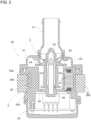
FIG. 2 is an axial-direction sectional view of a pump body. -
FIG. 3 is an exploded perspective view of the electric pump. -
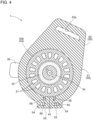
FIG. 4 is a sectional plan view of the electric pump. -
FIG. 5 is a partial front view of the electric pump. -
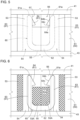
FIG. 6 is a sectional partial front view of the electric pump. -
FIG. 7 is a sectional partial plan view of the electric pump. -
FIG. 8 is a sectional partial plan view of an electric pump according to a second embodiment. -
FIG. 9 is a plan view of an elastic member in another configuration. - Hereinafter, embodiments of the present disclosure are described with reference to the drawings. An electric pump according to the present disclosure is provided at a cooling water supply system in an automobile, for example, However, application of the electric pump is not limited to automobiles, and the electric pump may be used for supplying fluid other than cooling water.
- As illustrated in
FIG. 1 to FIG. 7 , theelectric pump 1 includes apump unit 2, amotor 3 that drives thepump unit 2, apump body 40 that accommodates thepump unit 2 and themotor 3, anelastic member 50 that is provided around thepump body 40, and alock member 60 that is attached to theelastic member 50. As illustrated inFIG. 2 , thepump body 40 is configured by coupling apump housing 41 accommodating thepump unit 2, to amotor body 42 accommodating themotor 3. - As illustrated in
FIG. 1 , acylindrical suction port 21 and acylindrical discharge port 22 are formed in thepump housing 41. Thesuction port 21 and thedischarge port 22 each communicate with an impeller chamber 23 (refer toFIG. 2 ) formed inside thepump housing 41. Theimpeller chamber 23 accommodates animpeller 24. When theimpeller 24 rotates, fluid is sucked into theimpeller chamber 23 through thesuction port 21, and is discharged from theimpeller chamber 23 to thedischarge port 22. - As illustrated in
FIG. 2 , astator 31 is provided integrally with and inside themotor body 42 by insert molding. Arotor 32 in which magnets are incorporated is provided on a radial-direction inner side of thestator 31 while a gap exists between therotor 32 and thestator 31 in the radial direction. Arotational shaft 33 includes an end portion embedded in themotor body 42, and is configured to be non-rotatable relative to themotor body 42. Arotational member 34 is arranged on an outer peripheral side of therotational shaft 33 via a bearingmember 36, and is provided rotatably around therotational shaft 33. Therotor 32 into which the unillustrated magnets are inserted is arranged at one end portion of therotational member 34, and theimpeller 24 is formed at an opposite end portion of therotational member 34. According to the present configuration, therotor 32 rotates by magnetic force generated between therotor 32 and thestator 31, and therotational member 34 and theimpeller 24 rotate integrally with therotor 32. - The
pump body 40 includes adriver case 43 that accommodates a driver controlling themotor 3. Thedriver case 43 is provided to be coupled to themotor body 42, and thedriver case 43 and thepump housing 41 are located on both sides of themotor body 42 in such a way that themotor body 42 is sandwiched between thedriver case 43 and thepump housing 41. Themotor body 42 is provided with aconnector 35 for connecting themotor 3 to an electric power supply and a control system. - As illustrated in
FIG. 3 , themotor body 42 is generally cylindrical, and includes aflange 42a at an end portion on a side of thepump housing 41 and aflange 42c at an end portion on a side of thedriver case 43. Thedriver case 43 is provided in a cover shape for themotor body 42. Thus, thepump body 40 includes acylindrical portion 42b at which anannular portion 51 of the below-describedelastic member 50 is arranged, and a pair of theflanges annular portion 51 in a direction of the axis X of thecylindrical portion 42b, and a pair of theflanges annular portion 51 in the direction of the axis X. Thereby, a pair of theflanges electric pump 1 can prevent a problem that theannular portion 51 of the below-describedelastic member 50 moves in the axial direction of thecylindrical portion 42b and is detached from thepump body 40. - The
elastic member 50 is formed in an annular shape as illustrated inFIG. 3 , and is arranged in such a way as to be along an outer periphery (thecylindrical portion 42b) of the pump body 40 (refer toFIG. 1 andFIG. 4 ). In the present embodiment, theelastic member 50 is arranged at the outer periphery of themotor body 42 in the pump body 40 (refer toFIG. 2 andFIG. 4 ). Theelastic member 50 includes theannular portion 51 and anextension portion 52 connected to theannular portion 51, and theannular portion 51 is arranged at thecylindrical portion 42b of themotor body 42. Theannular portion 51 is arranged in such a way as to closely contact with thecylindrical portion 42b of thepump body 40. Theextension portion 52 extends from a part of an outer periphery of theannular portion 51, outward in the radial direction of thecylindrical portion 42b, and includes anopening 52a formed for attachment to an unillustrated bracket. Thereby, for example, the bracket is inserted into the opening 52b formed in theextension portion 52 connected to theannular portion 51, and thus, theelectric pump 1 is held by the bracket. Theelastic member 50 is made of a rubber material such as ethylene-propylene-diene monomer (EPDM) rubber. As illustrated inFIG. 3 , an innerperipheral surface 51a included in theannular portion 51 and contacting against themotor body 42 is formed into a shape conforming to an outer peripheral shape of thecylindrical portion 42b of themotor body 42. The innerperipheral surface 51a may include a recess-shaped lightened portion that does not contact against the outer periphery of thecylindrical portion 42b of themotor body 42. - The
elastic member 50 is split at a part of the peripheral direction in theannular portion 51. The splitting in the peripheral direction formsend portions annular portion 51, and theend portions end portions end portions portions 53. - As illustrated in
FIG. 7 , each of a pair of the penetration holes 54 and 54 is formed in an elongated hole that is elongated in the peripheral direction in a plan view. Each of a pair of the penetration holes 54 and 54 includes first andsecond hole portions annular portion 51, thefirst hole portion 54a has a width W1 substantially the same as a thickness of thelock member 60, and thesecond hole portion 54b has a width W2 larger than the width W1 of thefirst hole portion 54a. Thefirst hole portions annular portion 51. The width W1 of thefirst hole portion 54a substantially the same as the thickness of thelock member 60 enables thelock member 60 to be stably held by thefirst hole portion 54a. The width W2 of thesecond hole portion 54b larger than the width W1 of thefirst hole portion 54a enables thelock member 60 to be easily inserted into a pair of the penetration holes 54 and 54. - Both
end portions 53 in theannular portion 51 are formed to protrude outward in the radial direction of thecylindrical portion 42b of thepump body 40, and thus, for example, forming the wide penetration holes 54 and 54 in bothend portions 53 enables thelock member 60 to be easily inserted into the penetration holes 54 and 54. - The
lock member 60 is inserted into a pair of the penetration holes 54 and 54 so that theinner surface 51a of theannular portion 51 of theelastic member 50 comes into close contact with thecylindrical portion 42b of themotor body 42 of thepump body 40, and theannular portion 51 comes into close contact with thecylindrical portion 42b. In this manner, theannular portion 51 of theelastic member 50 comes into close contact with thecylindrical portion 42b of thepump body 40, and thereby, thepump body 40 in theelectric pump 1 can be reliably held by theelastic member 50. As illustrated inFIG. 3 , thelock member 60 has a U-shape constituted of a pair of holdingportions 61 extending in the direction of the axis X and aconnection portion 62 connecting a pair of the holdingportions 61 to each other. In the present embodiment, thelock member 60 is formed into a shape of a flat plate. Thelock member 60 can be produced by pressing a metal material or molding a hard resin or the like, for example. A pair of the holdingportions lock member 60 are inserted into a pair of the penetration holes 54 and 54. - As illustrated in
FIG. 5 and FIG. 6 , the holdingportion 61 of thelock member 60 includes aleg portion 63 and a slip-off prevention portion 64. Theleg portion 63 extends in the direction of the axis X, and the slip-off prevention portion 64 is connected to a distal end side in theleg portion 63. The slip-off prevention portion 64 protrudes toward theopposing leg portion 63, and is formed in a triangular shape including abottom surface 64a and aninclined surface 64b. Thebottom surface 64a extends toward theopposing leg portion 63 from an intermediate part in the direction of the axis X in theleg portion 63. Theinclined surface 64b is provided in such a way as to extend from anend portion 64c of thebottom surface 64a to anextension end 61a of the holdingportion 61. Theinclined surface 64b in the slip-off prevention portion 64 functions as a guide at the time of inserting thelock member 60 into the penetration holes 54. The holdingportions 61 of thelock member 60 can be pushed into and inserted into the penetration holes 54 while theend portions 64c of the slip-off prevention portions 64 are made to contact against inner surfaces of the penetration holes 54. Thelock member 60 is set in such a way that a distance between a pair of theleg portions - The
annular portion 51 includes ahole portion 55 that can accommodate theconnection portion 62 of thelock member 60 and that is formed inareas portions 61 of thelock member 60 are inserted) in the direction of the axis X and located between a pair of the penetration holes 54 and 54. As illustrated inFIG. 3 ,FIG. 5 ,FIG. 6 , andFIG. 7 , theannular portion 51 includes ahole portion 56 that communicates with a pair of the penetration holes 54 and 54 and that is formed on an opposite end side (a side where the extension ends 61a of the holdingportions 61 of thelock member 60 are located) in the direction of the axis X in theannular portion 51. A pair of the holdingportions lock member 60 are inserted into a pair of the penetration holes 54 and 54 in the direction of the axis X, until theend portions 64c of the slip-off prevention portions 64 become located within thehole portion 56. Thereby, thelock member 60 has been inserted into a pair of the penetration holes 54 and 54 in a state where the slip-off prevention portion 64 prevents thelock member 60 from slipping off from the penetration holes 54, and thus, thelock member 60 holds bothend portions 53 of theannular portion 51 pulled in such a way as to become closer to each other. As a result, according to theelectric pump 1, theannular portion 51 of theelastic member 50 is attached to thepump body 40 to be thereby brought into a state of closely contacting with thepump body 40, and thus, can stably holds thepump body 40. In this state, the extension ends 61a and 61a of thelock member 60 do not protrude from thehole portion 56 in the direction of the axis X. - A lock member for holding the
annular portion 51 at the outer periphery of thepump body 40 is needed in order that theannular portion 51 including the split part in the peripheral direction is attached to the outer periphery of thepump body 40. Here, arranging the lock member along the radial direction of theannular portion 51 needs measures such as a configuration where fastening portions protrude outward in the radial direction of theannular portion 51, and a configuration where the lock member is constituted by two members, for example, a bolt and a nut, and thus, theelectric pump 1 is increased in size. Meanwhile, as in the present embodiment, a pair of the penetration holes 54 and 54 along the direction of the axis X are provided in theannular portion 51, and thelock member 60 is inserted into a pair of the penetration holes 54 and 54 so that thelock member 60 does not largely protrude in the radial direction because of being inserted along the direction of the axis X, even when thelock member 60 is increased in size for making theannular portion 51 stably hold thepump body 40. In other words, theannular portion 51 does not need to be provided with the fastening portions protruding outward in the radial direction, and can be configured compactly. As a result, theelectric pump 1 held by theelastic member 50 has improved mountability to a vehicle or the like. - Further, according to the present embodiment, the
lock member 60 has the simple U-shaped configuration constituted of a pair of the holdingportions connection portion 62 that connects a pair of the holdingportions lock member 60 can be easily manufactured. Since a pair of the holdingportions lock member 60 extend in the direction of the axis X, a pair of the holdingportions annular portion 51. Thereby, theelastic member 50 in theelectric pump 1 has more improved attachability. - In order for the
lock member 60 to stably hold theannular portion 51 at thepump body 40, a pair of the holdingportions elastic member 50 along the direction of the axis X, for example. However, since a pair of the holdingportions lock member 60 are inserted into a pair of the penetration holes 54 and 54, a state of insertion of a pair of the holdingportions annular portion 51 unless a length of the holdingportion 61 is longer than a length of theelastic member 50 along the direction of the axis X. - In view of it, according to the present embodiment, as illustrated in
FIG. 1 ,FIG. 3 ,FIG. 5 , andFIG. 7 , theannular portion 51 in theelastic member 50 includes anotch portion 57 formed inward in the radial direction in an area that is included in theareas portions 61 to an intermediate location, and thus, theannular portion 51 is configured in such a way that a part of thelock member 60 is visible from an outside via thenotch portion 57. Specifically, thenotch portion 57 and thehole portion 56 communicate with each other, and the slip-off prevention portions 64 of thelock member 60 is visible from an outside through thenotch portion 57. Thenotch portion 57 is formed in theannular portion 51 from a side of the extension ends 61a of the holdingportions 61 along the direction of the axis X in such a way as to have a length equal to or smaller than a half length of theelastic member 50 in the direction of the axis X, for example. With the present configuration, thenotch portion 57 enables easy confirmation of whether positions of a pair of the holdingportions lock member 60 are appropriate, and thelock member 60 can be reliably arranged and attached at an appropriate position in theannular portion 51 by adjusting a position of thelock member 60, based on a result of the confirmation. In the present embodiment, thenotch portion 57 is set in such a way as to range over an area equal to or smaller than a half area of theannular portion 51 in the direction of the axis X. - In the peripheral direction of continuing to a pair of the penetration holes 54 and 54, the
lock member 60 inserted into a pair of the penetration holes 54 and 54 elastically deforms theannular portion 51 in a direction in which both endportions 53 become closer to each other. However, the elastic deformation less occurs by thelock member 60 at parts in theannular portion 51 and on an inner peripheral side closer to thepump body 40 than a pair of the penetration holes 54 and 54, and the parts on the inner peripheral side receive the reaction force in a direction of separating in theannular portion 51 and are thereby caused to be in an opened state (a state where the parts on the inner peripheral side in theend portions FIG. 3 ,FIG. 4 , andFIG. 7 , thepump body 40 includes a pair ofprotrusions cylindrical portion 42b of themotor body 42 and that face theend portions elastic member 50. Each of a pair of theprotrusions rotational shaft 33. Meanwhile, theannular portion 51 includes a pair ofrecesses 58 that are on the innerperipheral surface 51a and with which a pair of theprotrusions - As illustrated in
FIG. 7 , assuming that D1 is defined as a distance between a pair of the penetration holes 54 and 54 in the peripheral direction, and D2 is defined as a distance between a pair of therecesses annular portion 51 is configured in such a way that the distance D2 is shorter than the distance D1. Thereby, in theannular portion 51, the reaction force in the direction in which theend portions protrusions 44 included in themotor body 42 and engaging with a pair of therecesses peripheral surface 51a. As a result, theannular portion 51 can suppress the parts on an inner peripheral side of a pair of the penetration holes 54 and 54 from being opened. A pair of therecesses annular portion 51 are caused to engage with a pair of theprotrusions motor body 42, and thus, the annular portion 51 (elastic member 50) is easily positioned relative to thepump body 40, and theannular portion 51 is temporarily locked to thepump body 40 so that theelectric pump 1 allows theelastic member 50 to be quickly arranged on the outer periphery of thepump body 40. - The
lock member 60 to be inserted into a pair of the penetration holes 54 and 54 can be produced by pressing a metal material or molding a hard resin, for example, as described above. In this case, burrs occur on end portions of thelock member 60 on a side of a sag surface in some cases. Existence of the burrs on the end portions of thelock member 60 hinders thelock member 60 from being inserted into a pair of the penetration holes 54 and 54. There is a possibility that the burrs cause cracks in the penetration holes 54 and 54, thus leading to rupture of theannular portion 51. For this reason, in order to prevent the burrs from coming into contact against the penetration holes 54 and 54, processing of removing the burrs is needed in producing thelock member 60. However, removing the burrs needs a work step. In view of it, in the present embodiment, as illustrated inFIG. 7 , each of a pair of the penetration holes 54 and 54 in theannular portion 51 includesescape portions 59 that are located on a side closer to theopposite penetration hole 54 in the peripheral direction of theannular portion 51 and that expand inward and outward in the radial direction. Thereby, even when the burrs exist on thelock member 60, theescape portions 59 formed in a pair of the penetration holes 54 and 54 allow the burrs on thelock member 60, and can prevent the burrs from coming into contact against the penetration holes 54 and 54. As a result, processing of removing the burrs is not needed, and thus, thelock member 60 can be easily produced. In the example illustrated inFIG. 7 , the twocircular escape portions 59 are provided in each of a pair of the penetration holes 54 and 54, and the twoescape portions 59 are arranged on a radial-direction inner side and on a radial-direction outer side in thepenetration hole 54, and expand as far as a position closer to theopposite penetration hole 54 than a part 54a1 that is included in thefirst hole portion 54a and against which thelock member 60 comes into contact. Theescape portions 59 are formed both on a radial-direction inner side and on a radial-direction outer side in a pair of the penetration holes 54 and 54, and thus, the pressedlock member 60 can be attached without distinguishing whether the sag surface is on a front side or on a back side. - The following describes a method for attaching the
elastic member 50 to the motor body 42 (pump body 40). First, theend portions annular portion 51 of theelastic member 50 are opened, and thus, theannular portion 51 is arranged from a lateral side of thepump body 40 in such a way as to be along thecylindrical portion 42b of themotor body 42, and a pair of therecesses 58 are caused to engage with a pair of theprotrusions 44 of themotor body 42. Thereby, bothend portions 53 of theannular portion 51 of theelastic member 50 are positioned at predetermined locations on the outer periphery of themotor body 42. - Next, the
lock members 60 are inserted into a pair of the penetration holes 54 provided at bothend portions 53 of theannular portion 51 of theelastic member 50. Thelock member 60 is inserted into a pair of the penetration holes 54 until the slip-off prevention portions 64 becomes located in thehole portion 56. Thelock member 60 in an initial state cannot be inserted into the penetration holes 54 in theelastic member 50, and thelock member 60 in a state where a pair of the holdingportions off prevention portions 64 pass through the penetration holes 54, the restoring force causes a pair of theleg portions areas annular portion 51 is held in a state where both endportions 53 are close to each other. - As illustrated in
FIG. 8 , theelastic member 50 may be configured in such a way that theend portions annular portion 51 can be locked by each other in the peripheral direction. Specifically, one of theend portions 53 includes alock portion 53b, the other of theend portions 53 includes alock portion 53c, thelock portion 53b and thelock portion 53c are formed to have mutually locked uneven shapes in a plan view, and thelock portion 53b and thelock portion 53c are configured to overlap with each other in the radial direction of theannular portion 51. In the second embodiment, themotor body 42 is not provided with a pair of theprotrusions 44, and theannular portion 51 is not provided with a pair of therecesses 58. The other configurations are similar to those in the first embodiment. - According to the second embodiment, the
annular portion 51 is configured in such a way that thelock portions end portions end portions annular portion 51, theannular portion 51 can suppress the part on an inner peripheral side of a pair of the penetration holes 54 and 54 from being opened. Theend portions annular portion 51 in theelastic member 50 are locked by each other in the peripheral direction, and thus, theannular portion 51 can be temporarily locked to thepump body 40. Thereby, theelectric pump 1 allows theelastic member 50 to be quickly arranged at the outer periphery of thepump body 40. A configuration in which theend portions annular portion 51 can be locked by each other is not limited to the example illustrated inFIG. 8 , and may be any of other configurations as long as theend portions annular portion 51. -
- (1) As illustrated in
FIG. 9 , theannular portion 51 of theelastic member 50 may be formed entirely in a circular-ring shape in such a way that bothend portions 53 do not protrude outward in the radial direction, and has the same radial-direction thickness as that of the other parts in theelastic member 50. With the present configuration, theelastic member 50 becomes more compact than in the above-described embodiment, and for this reason, theelectric pump 1 has the more improved mountability. In the example illustrated inFIG. 9 , theelastic member 50 is constituted by only theannular portion 51. In a modified example of the example illustrated inFIG. 9 , theelastic member 50 may have theextension portion 52. - (2) In the example represented in the first embodiment, a pair of the
projections pump body 40, and a pair of therecesses peripheral surface 51a of theannular portion 51 of theelastic member 50. However, recesses may be provided on the outer peripheral surface 42ba of thepump body 40, and projections engaging with the recesses may be provided on the innerperipheral surface 51a of theannular portion 51. In the first embodiment, theelectric pump 1 may be configured without providing therecesses 58 on the innerperipheral surface 51a of theannular portion 51 and without providing theprotrusions 44 on the outer peripheral surface 42ba of thepump body 40. - (3) In the example represented in the above-described embodiment, the
lock member 60 inserted into a pair of the penetration holes 54 and 54 is configured as the single U-shaped member. However, thelock member 60 may be configured by combining a plurality of members. In the example represented in the above-described embodiment, a pair of therecesses protrusions recesses 58 and the number of theprotrusions 44 may be equal to or larger than three. - (4) In the example represented in the above-described embodiment, the
annular portion 51 of theelastic member 50 includes thehole portion 55 in which theconnection portion 62 of thelock member 60 is accommodated, and includes thehole portion 56 in which the slip-off prevention portions 64 of thelock member 60 are accommodated. However, theannular portion 51 may be configured without providing one or both of thehole portion 55 and thehole portion 56. Theelectric pump 1 may be configured without providing thenotch portion 57 in theannular portion 51. - The present disclosure can be widely applied to electric pumps each including an elastic member that holds a pump body.
-
- 1:
- Electric pump
- 40:
- Pump body
- 42:
- Motor body
- 42a, 42c:
- Flange
- 42b:
- Cylindrical portion
- 42ba:
- Outer peripheral surface
- 44:
- Protrusion
- 50:
- Elastic member
- 51:
- Annular portion
- 51a:
- Inner peripheral surface
- 52:
- Extension portion
- 52a:
- Opening
- 53:
- End portion
- 53b, 53c:
- Lock portion
- 54:
- Penetration hole
- 57:
- Notch portion
- 58:
- Recess
- 59:
- Escape portion
- 60:
- Lock member
- 61:
- Holding portion
- 61a:
- Extension end
- 62:
- Connection portion
- 63:
- Leg portion
- 64:
- Slip-off prevention portion
- D1:
- Distance between pair of penetration holes
- D2:
- Distance between pair of protrusions
- X:
- Axis
Claims (10)
- An electric pump comprising:a pump body;an annular elastic member to be arranged on an outer periphery of the pump body; anda lock member to be attached to the elastic member, whereinthe elastic member is split as a part of a peripheral direction, and includes a pair of penetration holes along an axial direction of the elastic member, at both end portions that face each other by the splitting of the peripheral direction, andthe lock member is inserted into the pair of penetration holes in such a way that the elastic member closely contacts with the pump body and holds the pump body.
- The electric pump according to Claim 1, wherein
the lock member has a U-shape that includes a pair of holding portions extending in the axial direction and a connection portion connecting a pair of the holding portions to each other, and a pair of the holding portions are inserted into the pair of penetration holes. - The electric pump according to Claim 2, whereinthe annular elastic member includes a notch portion formed inward in a radial direction in an area that is included in an area between the pair of penetration holes in the peripheral direction and that ranges along the axial direction from a side of an extension end of the holding portion to an intermediate location, anda part of the lock member is visible from an outside via the notch portion.
- The electric pump according to any one of Claims 1 to 3, whereinthe pump body includes a pair of protrusions protruding outward in a radial direction at positions that are on an outer peripheral surface of the pump body and that face the both end portions of the elastic member,the elastic member includes a pair of recesses with which a pair of the protrusions engage, anda distance between a pair of the recesses in the peripheral direction is shorter than a distance between a pair of the penetration holes in the peripheral direction.
- The electric pump according to any one of Claims 1 to 3, wherein
each of a pair of the penetration holes includes an escape portion that is located on a side closer to the opposite penetration hole in the peripheral direction of the elastic member and that expands inward and outward in a radial direction. - The electric pump according to any one of Claims 1 to 3, wherein
the annular elastic member is configured in such a way that the both end portions can be locked by each other in the peripheral direction. - The electric pump according to any one of Claims 1 to 3, whereinthe elastic member includes an annular portion including the both end portions, and an extension portion connected to the annular portion,the pump body includes a cylindrical portion with which the annular portion closely contacts, andthe extension portion extends from a part of an outer periphery of the annular portion, outward in a radial direction of the cylindrical portion, and an opening is formed in the extension portion.
- The electric pump according to any one of Claims 1 to 3, whereinthe elastic member includes an annular portion including the both end portions,the pump body includes a cylindrical portion with which the annular portion closely contacts, andthe annular portion is formed in such a way that the both end portions protrude outward in a radial direction of the cylindrical portion.
- The electric pump according to any one of Claims 1 to 3, whereinthe elastic member includes an annular portion including the both end portions,the pump body includes a cylindrical portion with which the annular portion closely contacts,the cylindrical portion includes a pair of protrusions protruding outward in a radial direction at positions that are on an outer peripheral surface of the cylindrical portion and that face the both end portions of the annular portion, andthe annular portion includes a pair of recesses with which a pair of the protrusions engage, and is arranged in such a way as to be along the cylindrical portion of the pump body, and a pair of the recesses engage with a pair of the protrusions.
- The electric pump according to any one of Claims 1 to 3, whereinthe elastic member includes an annular portion including the both end portions,the pump body includes a cylindrical portion with which the annular portion closely contacts, and a pair of flanges that are provided at both end portions in the cylindrical portion in the axial direction of the annular portion, anda pair of the flanges are provided in such a way as to be able to restrict movement of the annular portion in the axial direction.
Applications Claiming Priority (2)
| Application Number | Priority Date | Filing Date | Title |
|---|---|---|---|
| JP2022062594 | 2022-04-04 | ||
| PCT/JP2023/002810 WO2023195213A1 (en) | 2022-04-04 | 2023-01-30 | Electric pump |
Publications (2)
| Publication Number | Publication Date |
|---|---|
| EP4506574A1 true EP4506574A1 (en) | 2025-02-12 |
| EP4506574A4 EP4506574A4 (en) | 2025-08-13 |
Family
ID=88242659
Family Applications (1)
| Application Number | Title | Priority Date | Filing Date |
|---|---|---|---|
| EP23784508.6A Pending EP4506574A4 (en) | 2022-04-04 | 2023-01-30 | ELECTRIC PUMP |
Country Status (5)
| Country | Link |
|---|---|
| US (1) | US20250163938A1 (en) |
| EP (1) | EP4506574A4 (en) |
| JP (1) | JP7736175B2 (en) |
| CN (1) | CN119317781A (en) |
| WO (1) | WO2023195213A1 (en) |
Family Cites Families (14)
| Publication number | Priority date | Publication date | Assignee | Title |
|---|---|---|---|---|
| JPS5133735Y2 (en) * | 1972-05-20 | 1976-08-20 | ||
| JPS61101694A (en) * | 1984-10-24 | 1986-05-20 | Hitachi Ltd | Support structure of tank type liquid metal pump |
| US6424066B1 (en) * | 1999-11-12 | 2002-07-23 | Camco International, Inc. | System for reducing wear and improving longevity of a electric submergible pumping system |
| JP2007002811A (en) * | 2005-06-27 | 2007-01-11 | Nissan Motor Co Ltd | Support structure for parts |
| JP5021276B2 (en) | 2006-11-10 | 2012-09-05 | アスモ株式会社 | Rubber bracket and fluid pump device |
| JP2009092166A (en) * | 2007-10-10 | 2009-04-30 | S K Koki:Kk | Fixture for sheet-like material |
| DE102011085558A1 (en) | 2011-11-02 | 2013-05-02 | Robert Bosch Gmbh | Holder for fixing an aggregate, in particular a pump, to a motor vehicle |
| DE102016201560B4 (en) * | 2016-02-02 | 2024-02-01 | Robert Bosch Gmbh | Bracket for attaching a unit, in particular a pump, to a motor vehicle |
| DE102016209204A1 (en) * | 2016-05-27 | 2017-11-30 | Robert Bosch Gmbh | Device for controlling at least one fluid flow in a vehicle |
| JP6834300B2 (en) | 2016-09-27 | 2021-02-24 | アイシン精機株式会社 | Electric pump |
| DE102017216217A1 (en) * | 2017-09-13 | 2019-03-14 | Robert Bosch Gmbh | holder |
| CN208634090U (en) * | 2018-08-03 | 2019-03-22 | 北京车和家信息技术有限公司 | Electronic water pump damping frame and vehicle |
| JP2021139376A (en) | 2020-03-02 | 2021-09-16 | 株式会社フコク | Anti-vibration member |
| CN114056078B (en) * | 2020-07-30 | 2024-06-18 | 安徽威灵汽车部件有限公司 | Mounting bracket, water pump and vehicle |
-
2023
- 2023-01-30 JP JP2024514157A patent/JP7736175B2/en active Active
- 2023-01-30 EP EP23784508.6A patent/EP4506574A4/en active Pending
- 2023-01-30 WO PCT/JP2023/002810 patent/WO2023195213A1/en not_active Ceased
- 2023-01-30 CN CN202380032268.0A patent/CN119317781A/en active Pending
- 2023-01-30 US US18/840,782 patent/US20250163938A1/en active Granted
Also Published As
| Publication number | Publication date |
|---|---|
| US20250163938A1 (en) | 2025-05-22 |
| CN119317781A (en) | 2025-01-14 |
| EP4506574A4 (en) | 2025-08-13 |
| WO2023195213A1 (en) | 2023-10-12 |
| JPWO2023195213A1 (en) | 2023-10-12 |
| JP7736175B2 (en) | 2025-09-09 |
Similar Documents
| Publication | Publication Date | Title |
|---|---|---|
| US10533579B2 (en) | Electric pump and mounting structure of electric pump | |
| EP1493954B1 (en) | Twin component clip for fuel and brake lines | |
| EP0677894B1 (en) | Sealing device and method for producing a waterproof connector | |
| US7893572B2 (en) | Motor attachment assembly for plastic post isolation system | |
| US8449269B2 (en) | Electric pump and electric pump mounting structure | |
| JP5009725B2 (en) | Motor structure and method for assembling motor structure | |
| KR20090129982A (en) | Gear housing | |
| CN112421289A (en) | Sealing member and connector | |
| US20120076680A1 (en) | Mounting and damping system for a compressor | |
| EP3511592B1 (en) | Vibration-damping device body and vibration-damping device | |
| JP2003227581A (en) | Half mating prevention clip for connector | |
| AU2010354869B2 (en) | Grommet | |
| WO2012042855A1 (en) | Rotary connector device | |
| CN1864314A (en) | motor | |
| EP3417174B1 (en) | Automotive electrical coolant pump | |
| US20250163938A1 (en) | Electric pump | |
| JP2002330531A (en) | Grommet mounting structure on body panel | |
| CN101737392B (en) | Jacknuts and motors using jacknuts | |
| US7866967B2 (en) | Pump having an intermediate element with a pivot bearing within a rotor for connecting the rotor with a coupling device | |
| CN1670419A (en) | Quick-coupling device for motor vehicle ducts | |
| US11585440B2 (en) | Hole plug attachment structure | |
| JP2003134718A (en) | motor | |
| CN120345146A (en) | Grommet | |
| CN118510982A (en) | Cooler fan module for a motor vehicle | |
| US20230060455A1 (en) | Motor vehicle cooling system with an electric coolant pump |
Legal Events
| Date | Code | Title | Description |
|---|---|---|---|
| STAA | Information on the status of an ep patent application or granted ep patent |
Free format text: STATUS: THE INTERNATIONAL PUBLICATION HAS BEEN MADE |
|
| PUAI | Public reference made under article 153(3) epc to a published international application that has entered the european phase |
Free format text: ORIGINAL CODE: 0009012 |
|
| STAA | Information on the status of an ep patent application or granted ep patent |
Free format text: STATUS: REQUEST FOR EXAMINATION WAS MADE |
|
| 17P | Request for examination filed |
Effective date: 20240927 |
|
| AK | Designated contracting states |
Kind code of ref document: A1 Designated state(s): AL AT BE BG CH CY CZ DE DK EE ES FI FR GB GR HR HU IE IS IT LI LT LU LV MC ME MK MT NL NO PL PT RO RS SE SI SK SM TR |
|
| REG | Reference to a national code |
Ref country code: DE Ref legal event code: R079 Free format text: PREVIOUS MAIN CLASS: F04D0029620000 Ipc: F04D0029660000 |
|
| DAV | Request for validation of the european patent (deleted) | ||
| DAX | Request for extension of the european patent (deleted) | ||
| A4 | Supplementary search report drawn up and despatched |
Effective date: 20250714 |
|
| RIC1 | Information provided on ipc code assigned before grant |
Ipc: F04D 29/66 20060101AFI20250708BHEP Ipc: F04D 29/62 20060101ALI20250708BHEP Ipc: F04D 29/60 20060101ALI20250708BHEP Ipc: F04B 53/00 20060101ALI20250708BHEP Ipc: F04B 53/16 20060101ALI20250708BHEP Ipc: F04B 17/03 20060101ALI20250708BHEP |