EP4506556A1 - Elongated journal bearing for high gear ratio epicyclic fan drive gear system - Google Patents
Elongated journal bearing for high gear ratio epicyclic fan drive gear system Download PDFInfo
- Publication number
- EP4506556A1 EP4506556A1 EP24192933.0A EP24192933A EP4506556A1 EP 4506556 A1 EP4506556 A1 EP 4506556A1 EP 24192933 A EP24192933 A EP 24192933A EP 4506556 A1 EP4506556 A1 EP 4506556A1
- Authority
- EP
- European Patent Office
- Prior art keywords
- gear
- aft
- undercut
- fan drive
- recited
- Prior art date
- Legal status (The legal status is an assumption and is not a legal conclusion. Google has not performed a legal analysis and makes no representation as to the accuracy of the status listed.)
- Pending
Links
Images




Classifications
-
- F—MECHANICAL ENGINEERING; LIGHTING; HEATING; WEAPONS; BLASTING
- F02—COMBUSTION ENGINES; HOT-GAS OR COMBUSTION-PRODUCT ENGINE PLANTS
- F02C—GAS-TURBINE PLANTS; AIR INTAKES FOR JET-PROPULSION PLANTS; CONTROLLING FUEL SUPPLY IN AIR-BREATHING JET-PROPULSION PLANTS
- F02C7/00—Features, components parts, details or accessories, not provided for in, or of interest apart form groups F02C1/00 - F02C6/00; Air intakes for jet-propulsion plants
- F02C7/36—Power transmission arrangements between the different shafts of the gas turbine plant, or between the gas-turbine plant and the power user
-
- F—MECHANICAL ENGINEERING; LIGHTING; HEATING; WEAPONS; BLASTING
- F02—COMBUSTION ENGINES; HOT-GAS OR COMBUSTION-PRODUCT ENGINE PLANTS
- F02K—JET-PROPULSION PLANTS
- F02K3/00—Plants including a gas turbine driving a compressor or a ducted fan
- F02K3/02—Plants including a gas turbine driving a compressor or a ducted fan in which part of the working fluid by-passes the turbine and combustion chamber
- F02K3/04—Plants including a gas turbine driving a compressor or a ducted fan in which part of the working fluid by-passes the turbine and combustion chamber the plant including ducted fans, i.e. fans with high volume, low pressure outputs, for augmenting the jet thrust, e.g. of double-flow type
- F02K3/06—Plants including a gas turbine driving a compressor or a ducted fan in which part of the working fluid by-passes the turbine and combustion chamber the plant including ducted fans, i.e. fans with high volume, low pressure outputs, for augmenting the jet thrust, e.g. of double-flow type with front fan
-
- F—MECHANICAL ENGINEERING; LIGHTING; HEATING; WEAPONS; BLASTING
- F02—COMBUSTION ENGINES; HOT-GAS OR COMBUSTION-PRODUCT ENGINE PLANTS
- F02C—GAS-TURBINE PLANTS; AIR INTAKES FOR JET-PROPULSION PLANTS; CONTROLLING FUEL SUPPLY IN AIR-BREATHING JET-PROPULSION PLANTS
- F02C7/00—Features, components parts, details or accessories, not provided for in, or of interest apart form groups F02C1/00 - F02C6/00; Air intakes for jet-propulsion plants
- F02C7/06—Arrangements of bearings; Lubricating
-
- F—MECHANICAL ENGINEERING; LIGHTING; HEATING; WEAPONS; BLASTING
- F16—ENGINEERING ELEMENTS AND UNITS; GENERAL MEASURES FOR PRODUCING AND MAINTAINING EFFECTIVE FUNCTIONING OF MACHINES OR INSTALLATIONS; THERMAL INSULATION IN GENERAL
- F16H—GEARING
- F16H1/00—Toothed gearings for conveying rotary motion
- F16H1/28—Toothed gearings for conveying rotary motion with gears having orbital motion
-
- F—MECHANICAL ENGINEERING; LIGHTING; HEATING; WEAPONS; BLASTING
- F16—ENGINEERING ELEMENTS AND UNITS; GENERAL MEASURES FOR PRODUCING AND MAINTAINING EFFECTIVE FUNCTIONING OF MACHINES OR INSTALLATIONS; THERMAL INSULATION IN GENERAL
- F16H—GEARING
- F16H57/00—General details of gearing
- F16H57/04—Features relating to lubrication or cooling or heating
- F16H57/0467—Elements of gearings to be lubricated, cooled or heated
- F16H57/0479—Gears or bearings on planet carriers
-
- F—MECHANICAL ENGINEERING; LIGHTING; HEATING; WEAPONS; BLASTING
- F16—ENGINEERING ELEMENTS AND UNITS; GENERAL MEASURES FOR PRODUCING AND MAINTAINING EFFECTIVE FUNCTIONING OF MACHINES OR INSTALLATIONS; THERMAL INSULATION IN GENERAL
- F16H—GEARING
- F16H57/00—General details of gearing
- F16H57/08—General details of gearing of gearings with members having orbital motion
-
- F—MECHANICAL ENGINEERING; LIGHTING; HEATING; WEAPONS; BLASTING
- F05—INDEXING SCHEMES RELATING TO ENGINES OR PUMPS IN VARIOUS SUBCLASSES OF CLASSES F01-F04
- F05D—INDEXING SCHEME FOR ASPECTS RELATING TO NON-POSITIVE-DISPLACEMENT MACHINES OR ENGINES, GAS-TURBINES OR JET-PROPULSION PLANTS
- F05D2220/00—Application
- F05D2220/30—Application in turbines
- F05D2220/36—Application in turbines specially adapted for the fan of turbofan engines
-
- F—MECHANICAL ENGINEERING; LIGHTING; HEATING; WEAPONS; BLASTING
- F05—INDEXING SCHEMES RELATING TO ENGINES OR PUMPS IN VARIOUS SUBCLASSES OF CLASSES F01-F04
- F05D—INDEXING SCHEME FOR ASPECTS RELATING TO NON-POSITIVE-DISPLACEMENT MACHINES OR ENGINES, GAS-TURBINES OR JET-PROPULSION PLANTS
- F05D2240/00—Components
- F05D2240/50—Bearings
-
- F—MECHANICAL ENGINEERING; LIGHTING; HEATING; WEAPONS; BLASTING
- F05—INDEXING SCHEMES RELATING TO ENGINES OR PUMPS IN VARIOUS SUBCLASSES OF CLASSES F01-F04
- F05D—INDEXING SCHEME FOR ASPECTS RELATING TO NON-POSITIVE-DISPLACEMENT MACHINES OR ENGINES, GAS-TURBINES OR JET-PROPULSION PLANTS
- F05D2240/00—Components
- F05D2240/50—Bearings
- F05D2240/53—Hydrodynamic or hydrostatic bearings
-
- F—MECHANICAL ENGINEERING; LIGHTING; HEATING; WEAPONS; BLASTING
- F05—INDEXING SCHEMES RELATING TO ENGINES OR PUMPS IN VARIOUS SUBCLASSES OF CLASSES F01-F04
- F05D—INDEXING SCHEME FOR ASPECTS RELATING TO NON-POSITIVE-DISPLACEMENT MACHINES OR ENGINES, GAS-TURBINES OR JET-PROPULSION PLANTS
- F05D2240/00—Components
- F05D2240/50—Bearings
- F05D2240/54—Radial bearings
-
- F—MECHANICAL ENGINEERING; LIGHTING; HEATING; WEAPONS; BLASTING
- F05—INDEXING SCHEMES RELATING TO ENGINES OR PUMPS IN VARIOUS SUBCLASSES OF CLASSES F01-F04
- F05D—INDEXING SCHEME FOR ASPECTS RELATING TO NON-POSITIVE-DISPLACEMENT MACHINES OR ENGINES, GAS-TURBINES OR JET-PROPULSION PLANTS
- F05D2250/00—Geometry
- F05D2250/70—Shape
- F05D2250/73—Shape asymmetric
-
- F—MECHANICAL ENGINEERING; LIGHTING; HEATING; WEAPONS; BLASTING
- F05—INDEXING SCHEMES RELATING TO ENGINES OR PUMPS IN VARIOUS SUBCLASSES OF CLASSES F01-F04
- F05D—INDEXING SCHEME FOR ASPECTS RELATING TO NON-POSITIVE-DISPLACEMENT MACHINES OR ENGINES, GAS-TURBINES OR JET-PROPULSION PLANTS
- F05D2260/00—Function
- F05D2260/40—Transmission of power
- F05D2260/403—Transmission of power through the shape of the drive components
- F05D2260/4031—Transmission of power through the shape of the drive components as in toothed gearing
- F05D2260/40311—Transmission of power through the shape of the drive components as in toothed gearing of the epicyclical, planetary or differential type
-
- F—MECHANICAL ENGINEERING; LIGHTING; HEATING; WEAPONS; BLASTING
- F05—INDEXING SCHEMES RELATING TO ENGINES OR PUMPS IN VARIOUS SUBCLASSES OF CLASSES F01-F04
- F05D—INDEXING SCHEME FOR ASPECTS RELATING TO NON-POSITIVE-DISPLACEMENT MACHINES OR ENGINES, GAS-TURBINES OR JET-PROPULSION PLANTS
- F05D2260/00—Function
- F05D2260/98—Lubrication
-
- F—MECHANICAL ENGINEERING; LIGHTING; HEATING; WEAPONS; BLASTING
- F16—ENGINEERING ELEMENTS AND UNITS; GENERAL MEASURES FOR PRODUCING AND MAINTAINING EFFECTIVE FUNCTIONING OF MACHINES OR INSTALLATIONS; THERMAL INSULATION IN GENERAL
- F16H—GEARING
- F16H57/00—General details of gearing
- F16H57/08—General details of gearing of gearings with members having orbital motion
- F16H2057/085—Bearings for orbital gears
Definitions
- a turbine engine typically includes a fan section, a compressor section, a combustor section and a turbine section.
- a speed reduction device such as an epicyclical gear assembly may be utilized to drive the fan section such that the fan section may rotate at a speed different than the turbine section so as to increase the overall propulsive efficiency of the engine.
- a carrier may support a plurality of planetary gears and rotate about an engine axis. Rotation of the carrier can present challenges for supporting and communicating lubricant to the planetary gears. Turbine engine manufacturers continue to seek further improvements to engine performance including improvements to thermal, transfer and propulsive efficiencies.
- a fan drive gear system for a turbine engine includes, among other possible things, a sun gear that is configured to be driven by an engine shaft rotatable about an axis, a plurality of compound intermediate gears, each of the plurality of intermediate gears includes a first gear portion and a second gear portion, the second gear portion includes a forward gear portion and an aft gear portion, a ring gear assembly that includes a forward ring gear that is engaged to the forward gear portion and an aft ring gear that is engaged to the aft gear portion, a carrier that supports rotation of the plurality of intermediate gears, and a plurality of journal bearing assemblies that correspond with the plurality of intermediate gears, each of the plurality of journal bearing assemblies includes a ratio of a journal length to a journal diameter that is between 1.5 and 6.
- the ring gear assembly is fixed to a static engine structure and the carrier is rotatable about the axis.
- the ring gear assembly includes a forward web portion that supports the forward ring gear and an aft web portion that supports the aft ring gear and each of the forward web portion and the aft web portion include an axial width that is between 10% and 25% of an axial width of each of the forward ring gear and the aft ring gear.
- an axial clearance between the first gear portion and each of the forward ring gear and the aft ring gear is greater than about 0.08 inches (2.03 mm).
- each of the plurality of compound intermediate gear include at least one lubricant exhaust opening between the forward gear portion and the aft gear portion.
- each of the forward portion and the aft portion includes a gear bearing surface with an axial width that matches an axial width of a corresponding one of the forward gear portion and the aft gear portion.
- each of the forward portion and the aft portion includes a gear bearing surface with an axial width that is greater than an axial width of the corresponding one of the forward gear portion and the aft gear portion.
- each of the forward portion and the aft portion include an outer undercut and an inner undercut.
- the outer undercut faces axially outward and the inner undercut faces axially inward toward the middle portion.
- the outer undercut and the inner undercut have equal axial lengths.
- each of the forward portion and the aft portion include an outer undercut and an inner undercut.
- the outer undercut faces axially outward and the inner undercut faces axially inward toward the middle portion.
- An axial length of the inner undercut is different than that of the outer undercut.
- each of the forward portion and the aft portion include an outer undercut and an inner undercut.
- the outer undercut faces axially outward and the inner undercut faces axially inward toward the middle portion.
- a radial thickness of the inner undercut is different than that of the outer undercut.
- each of the forward portion and the aft portion include an outer undercut and an inner undercut.
- the outer undercut faces axially outward and the inner undercut faces axially inward toward the middle portion.
- a radial thickness of the inner undercut and the outer undercut are the same.
- the middle portion includes a bearing surface that supports the first gear portion.
- the middle portion includes an outer diameter that is less than each of the forward portion and the aft portion.
- each of the plurality of journal bearing assemblies includes a lubricant supply holes that are configured to transfer lubricant to an interface with an inner surface of a corresponding one of the plurality of compound intermediate gears.
- a turbine engine assembly includes, among other possible things, a static engine structure, a fan section that includes a plurality of blades that are rotatable about an axis and a fan drive gear system that includes a sun gear that is configured to be driven by an engine shaft that is rotatable about the axis and a plurality of compound intermediate gears.
- Each of the plurality of intermediate gears includes a first gear portion and a second gear portion.
- the second gear portion includes a forward gear portion and an aft gear portion.
- a ring gear assembly includes a forward ring gear that is engaged to the forward gear portion and an aft ring gear that is engaged to the aft gear portion.
- the ring gear assembly is fixed to the engine static structure.
- a carrier supports rotation of the plurality of intermediate gears, the carrier is rotatable about the axis.
- a plurality of journal bearing assemblies correspond with the plurality of intermediate gears, each of the plurality of journal bearing assemblies includes a ratio of a journal length to a journal diameter that is between 1.5 and 6 and each of the plurality of journal bearing assemblies includes a lubricant supply holes that are configured to communicate lubricant to an interface with an inner surface of a corresponding one of the plurality of compound intermediate gears, and a fan drive shaft that is coupled to the carrier.
- the ring gear assembly includes a forward web portion that supports the forward ring gear and an aft web portion that supports the aft ring gear and each of the forward web portion and the aft web portion include an axial width that is between 10% and 25% of an axial width of each of the forward ring gear and the aft ring gear.
- each of the plurality of journal bearings includes a forward portion that supports the forward gear portion, an aft portion supports the aft gear portion, and a middle portion and each of the forward portion and the aft portion includes a gear bearing surface with an axial width that matches an axial width of a corresponding one of the forward gear portion and the aft gear portion.
- each of the plurality of journal bearings includes a forward portion that supports the forward gear portion, an aft portion supports the aft gear portion, and a middle portion and each of the forward portion and the aft portion includes a gear bearing surface with an axial width that is greater than an axial width of the corresponding one of the forward gear portion and the aft gear portion.
- each of the forward portion and the aft portion include an outer undercut and an inner undercut.
- the outer undercut faces axially outward and the inner undercut faces axially inward toward the middle portion.
- the outer undercut and the inner undercut have equal axial lengths.
- Figure 1 schematically illustrates a gas turbine engine 20 with an epicyclic fan drive gear system 48 having a compound intermediate gear and an elongated journal bearing.
- the intermediate gear and elongated journal bearing are supported in a rotatable carrier coupled to a fan drive shaft 62 for driving a fan section 22.
- the example fan drive gear system 48 provides high gear ratios and is configured to operate within a limited design space.
- the gas turbine engine 20 is disclosed herein as a two-spool turbofan that generally incorporates a fan section 22, a compressor section 24, a combustor section 26 and a turbine section 28.
- the fan section 22 drives air along a bypass flow path B in a bypass duct defined within a nacelle 18, and also drives air along a core flow path C for compression and communication into the combustor section 26 then expansion through the turbine section 28.
- the exemplary engine 20 generally includes a low speed spool 30 and a high speed spool 32 mounted for rotation about an engine central longitudinal axis A relative to an engine static structure 36 via several bearing systems 38. It should be understood that various bearing systems 38 at various locations may alternatively or additionally be provided, and the location of bearing systems 38 may be varied as appropriate to the application.
- the low speed spool 30 generally includes an inner shaft 40 that interconnects, a first (or low) pressure compressor 44 and a first (or low) pressure turbine 46.
- the inner shaft 40 is connected to a fan section 22 through a speed change mechanism, which in exemplary gas turbine engine 20 is illustrated as the fan drive gear system 48 to drive the fan section 22 at a lower speed than the low speed spool 30.
- the high speed spool 32 includes an outer shaft 50 that interconnects a second (or high) pressure compressor 52 and a second (or high) pressure turbine 54.
- the low pressure turbine 46 includes a plurality of turbine rotors 34.
- a combustor 56 is arranged in exemplary gas turbine 20 between the high pressure compressor 52 and the high pressure turbine 54.
- a mid-turbine frame 58 of the engine static structure 36 may be arranged generally between the high pressure turbine 54 and the low pressure turbine 46.
- the mid-turbine frame 58 further supports bearing systems 38 in the turbine section 28.
- the inner shaft 40 and the outer shaft 50 are concentric and rotate via bearing systems 38 about the engine central longitudinal axis A which is collinear with their longitudinal axes.
- the core airflow is compressed by the low pressure compressor 44 then the high pressure compressor 52, mixed and burned with fuel in the combustor 56, then expanded over the high pressure turbine 54 and low pressure turbine 46.
- the mid-turbine frame 58 includes airfoils 60 which are in the core airflow path C.
- the turbines 46, 54 rotationally drive the respective low speed spool 30 and high speed spool 32 in response to the expansion. It will be appreciated that each of the positions of the fan section 22, compressor section 24, combustor section 26, turbine section 28, and fan drive gear system 48 may be varied.
- the fan drive gear system 48 may be located aft of the low pressure compressor 44, or aft of the combustor section 26 or even aft of turbine section 28, and fan section 22 may be positioned forward or aft of the fan drive gear system 48.
- the engine 20 in one example is a high-bypass geared aircraft engine.
- the example engine 20 includes a bypass ratio greater than 20, with an example embodiment being greater than 32 and less than 72.
- the fan drive gear system 48 is an epicycle gear train with a gear reduction ratio of greater than about 5:1 and less than about 18:1. In another example embodiment, the fan drive gear system 48 provides a gear reduction ratio of between 8:1 and 13.5:1.
- the gear system 48 is coupled to the fan shaft 62 to drive the fan section 22 about the engine axis A. It should be understood, however, that the above parameters are only exemplary of one embodiment of a geared engine architecture and that the present disclosure is applicable to other gas turbine engine architectures including turbofan, turboshaft and open rotor engines.
- the example fan drive gear system 48 is an epicyclic gear system with a sun gear 64 engaged to a plurality of compound intermediate gears 66 supported by a rotating carrier 70.
- a ring gear assembly 68 circumscribes the intermediate gears 70 and is fixed to a static engine structure 36.
- the intermediate gears 66 are compound gears that have two or more gear interfaces of different sizes that are fixed together and rotate at a common speed.
- three (3) intermediate gears 66 are supported by the carrier 70 and rotate about a corresponding one of axes 202.
- Each of the intermediate gears 66 include a gear interface with the sun gear 64 and a gear interface with the fixed ring gear assembly 68.
- the example gear system 48 is shown in a simplified schematic view that illustrates gear interfaces with a single compound intermediate gear 66.
- the example compound intermediate gear 66 includes a first gear portion 74 and a second gear portion 76.
- the first gear portion 74 is engaged to the sun gear 64.
- the sun gear 64 is driven by the inner shaft 40 that is coupled to the LPT 46.
- the inner shaft 40 is shown by way of example as the driving input, other engine shafts could be coupled to the sun gear 64 to provide the driving input.
- the first gear portion 74 includes a first diameter 198 and the second gear portion 76 includes a smaller second diameter 200.
- the first diameter 198 and the second diameter 200 represent relative diameters that are tailored to provide a desired gear reduction through the gear system.
- gears have several different diameters that are utilized for different purposes and reflect different gear geometric portions. Accordingly, the example diameters 198, 200 may be any diameter commonly utilized to describe a gear. For example, pitch diameter, tip diameter, root diameter and/or reference diameter.
- the second gear portion 76 includes a forward gear portion 78 and an aft gear portion 80.
- the second gear portion 76 is split to enable a larger overall gear face width 90 to accommodate torque transmitted through the intermediate gear 66.
- the forward and aft gear portions 78, 80 are engaged to the ring assembly 68.
- the ring assembly 68 includes a forward ring gear 82 and an aft ring gear 84 that are each engaged to a corresponding part of the second gear portion 76.
- the forward ring gear 82 and the aft ring gear 84 are supported by a corresponding one of a forward web portion 86 and an aft web portion 88.
- the compound intermediate gear 66 is supported by the carrier 70.
- the carrier 70 is coupled to the fan shaft 62.
- the fan shaft 62 is coupled to a fan hub 72 that supports the plurality of fan blades 42.
- the specific structure of the fan section 22 may differ from the disclosed example and remain within the scope and contemplation of this disclosure.
- the compound intermediate gear 66 include a web portion 91 that supports the first gear portion 74 between the forward gear portion 78 and the aft gear portion 80.
- the web portion 91 includes a width 92 and is spaced a distance 94 apart from either of the forward gear portion 78 and the aft gear portion 80.
- the width 92 and distance 94 provide for manufacture of gear teeth, schematically indicated at 93, for the entire face width 90 of each of the forward and aft gear portions 78, 80.
- the example compound intermediate gear 66 is a one-piece part with integrally formed gear portions 74, 76.
- a multi-part compound intermediate gear could also be utilized and is within the contemplation of this disclosure.
- the distance 94 provides a clearance space for a rotating tool to form gear teeth schematically shown at 93 along the entire face width.
- the specific distance 94 and width 92 is tailored to gear specific configurations for a specific gear system configuration.
- the clearance 94 is between about 0.75 inches (19.1 mm) and 1.50 inches (38.1 mm).
- the clearance 94 is between about 0.80 inches (20.3 mm) and 1.25 inches (31.8 mm).
- the clearance 94 is greater than about 0.80 inches (20.3 mm).
- the axial width 92 of the web portion 91 is between 10% and 25% of the axial face width 74. In another example embodiment, the axial width 92 is about 15% of the axial face width 74.
- the ring gear assembly 68 includes ring gear portions 82, 84 that are spaced a distance 98 from the first gear portion 74.
- the webs 86, 88 each include a width 96 and support the corresponding forward ring gear portion 82 and an aft ring gear portion 84.
- the distance 98 defines a minimum clearance between portions of the fixed ring gear assembly 68 and the rotating intermediate gear 66.
- the distance 98 may be between 0.08 and 0.18 inches (between 2.03 and 4.57 mm). In still another example embodiment, the clearance 98 is greater than about 0.80 inches.
- an example clearance is disclosed, other distances may be utilized to accommodate application specific requirements and fabrication processes.
- each ring gear portion 82, 84 is attached directly to the engine static structure 36 and not directly connected to each other.
- the forward ring gear portion 82 and the aft ring gear portion 84 each includes a face width 81 that is proportional to the axial width 90 of the forward and aft gear portions of the intermediate gear 66.
- the width 96 is between 10% and 25% of the face width 81. In another example embodiment the width 96 is about 15% of the face width 81.
- Face width 81 is between 80% and 100% of Face width 90 in one embodiment, and between 85% and 95% of face width 90 in another embodiment.
- an intermediate gear 66 is shown with an example journal bearing 100.
- the journal bearing 100 includes an elongated length 104 to accommodate the increased axial width of the intermediate gear 66.
- the journal bearing 100 further includes an outer diameter 102 that corresponds to a bearing surface 101.
- the increased length 104 is reflected as a ratio between the length 104 and the outer diameter 102.
- a ratio of the length 104 to the outer diameter 102 is between 1.5 and 6.
- the ratio of the length 104 to the outer diameter 102 is between 2 and 4.
- the journal bearing 100 is illustrated as a one-piece part with features for supporting corresponding forward and aft gear portions 78, 80 of the intermediate gear 66.
- the example journal bearing 100 includes a forward portion 108, an aft portion 110 and a middle portion 112.
- the forward and aft portions 108, 110 support a corresponding forward and aft gear portion 78, 80.
- the journal bearing 100 includes a main lubricant passage 114 and radial lubricant passages 116 arranged to communicate a lubricant flow to rotating interfaces.
- the forward and aft portions 108, 110 have the bearing surface 101 with a length 106.
- the length 106 corresponds with the width 90 of each of the forward and aft gear portions 78, 80.
- Each of the bearing portions 108, 110 include outer undercuts 120 and inner undercuts 122.
- the outer and inner undercuts 120, 122 enable tailoring of a stiffness of the journal bearing 100.
- the middle portion 112 of the example journal bearing 100 includes a reduced outer diameter 103 as compared to the outer diameter 102 of the bearing surfaces 101.
- the bearing surfaces 101 in this example are spaced apart from the inner gear surface that corresponds with the first gear portion 74.
- the intermediate gear 66 may provide sufficient stiffness for loads on the first gear portion 74 so as to not require support by the journal bearing 100.
- journal bearing 124 is shown with forward and aft portions 130, 132 with a bearing surface 125 of a length 126.
- the length 126 extends inwardly to support the first gear portion 74.
- the middle portion 134 is smaller with the wider forward and aft portions 130, 132 that correspond to the increased length of the bearing surface 125.
- the forward portion 130 and the aft portion 132 includes a gear bearing surface 125 with the axial width 126 greater than the axial face width 90 of the corresponding one of the forward gear portion 78 and the aft gear portion 80.
- the journal bearing 124 includes the same main lubricant passage 114 that supplies radial passages 116. Outlets 128 are provided on either side of the web 91 and are located further inward to accommodate the increased length of the bearing surface 126.
- the example journal bearing 124 maintains the increased length 104 relative to the diameter 102 of the bearing surface 126.
- journal bearing 136 is shown that illustrates different undercut configuration embodiments.
- the example journal bearing 136 includes a middle portion 146 with a smaller outer diameter 148 than the outer diameter 140 of the bearing surfaces 135.
- the length 138 and outer diameter 140 are related by the previously disclosed ratios.
- the main lubricant passage 114 and radial lubricant passage 116 are shown and provided lubricant to the bearing surfaces 135.
- journal bearing 136 The configuration of the undercuts is tailored to generate a desired stiffness of the journal bearing 136 to accommodate loads.
- the previous disclosed and described journal bearings 100, 124 were generally symmetrical about the axis of rotation and between forward and aft portions, the journal bearing may be asymmetric to accommodate loads that may be biased forward or aft from an axial centerline of the intermediate gear 66.
- the example journal bearing 136 illustrates various different geometries for undercuts that may be utilized to tailor stiffness of the bearing surfaces 135 to accommodate operational gear loads.
- the example undercut 150 includes a thickness 158 and length 160 that is formed by the removal of material to define a gap.
- the thickness 158 and length 160 are tailored to define a stiffness of the journal bearing 136.
- the undercut lengths 160, 162, 166, 170 are individually proportional to the journal bearing surface length 126.
- the ratio of bearing surface length 126 to a single undercut length 160, 162, 166, 170 is between 4 and 7.
- the ratio of bearing surface length 126 to undercut length 160, 162, 166, 170 is between 3 and 10.
- the undercut 152 is shown with a length 162 that is smaller than that of the undercut 150.
- the undercut 152 further includes a thickness 164 that is substantially the same as that of the undercut 150.
- the change in length of the undercut 152 increases stiffness of the bearing surface 135.
- Another example undercut 154 includes a length 166 and thickness 168.
- thickness 168 is increased over the undercut 150 to provide the desired modification to stiffness.
- the length 166 may be the same as the length 160 but the undercut 154 provides an increase in stiffness due to the increased thickness 168.
- the undercut 156 is illustrated with an increased radius cutout area 174.
- the undercut 156 includes a thickness 172 and length 170 that are substantially the same as the undercut 150. However, the increased radius cutout area 174 provides a different stiffness.
- each of the forward portion 142 and the aft portion 144 include an outer undercut 151 and an inner undercut 153.
- the outer undercuts 151 face axially outward and the inner undercuts 153 face axially inward toward the middle portion 146.
- the axial lengths 162, 166 of the inner undercuts 153 are different than the axial lengths 160, 170 of at least one of the outer undercuts 151.
- each of the forward portion 142 and the aft portion 144, a radial thickness 164, 168 of at least one of the inner undercuts 153 is different than the radial thickness 158, 172 of at least one of the outer undercuts 151.
- journal bearing 176 includes a forward portion 178, an aft portion 180 and a middle portion 182.
- the example middle portion 182 includes a center support area 184 with an outer diameter 185.
- the outer diameter 185 may be the same or substantially the same as outer diameter 175 of bearing surfaces 194.
- the center support area 184 includes a center bearing surface 196.
- the center bearing surface 196 provides support for the first gear portion of the compound intermediate gear 66.
- the center bearing surface 196 may also be utilized to adjust overall stiffness.
- the journal bearing 176 includes outer undercuts 186 and inner undercuts 188.
- the outer undercuts 186 open outward toward ends of the journal bearing 176.
- the inner undercuts 188 open inward toward the middle area 182 and each other.
- each of the forward portion 178 and the aft portion 180 include an outer undercut 186 and an inner undercut 188.
- the outer undercut 188 faces axially outward and the inner undercut 188 faces axially inward toward the middle portion 182.
- the example outer undercut 186 and the example inner undercut 186 have equal axial lengths 187 and equal radial thicknesses 189.
- the example outer undercuts 186 and inner undercuts 188 are configured the same. However, the outer undercuts 186 and the inner undercuts 188 may be configured differently to accommodate localized loading and remain within the scope and contemplation of this disclosure.
- the middle Section 184 may also have undercuts similar to 186, 188 in order to modify stiffness.
- the middle section 184 may also include radial lubricant passages similar to 192 if the surface 196 is utilized as a bearing surface.
- example compound intermediate gear and example journal bearings includes features that accommodate increased gear loading within a limited design space.
Landscapes
- Engineering & Computer Science (AREA)
- General Engineering & Computer Science (AREA)
- Chemical & Material Sciences (AREA)
- Combustion & Propulsion (AREA)
- Mechanical Engineering (AREA)
- General Details Of Gearings (AREA)
Abstract
A fan drive gear system (48) for a turbine engine includes a gear system with a plurality of compound intermediate gears (66) that each include a first gear portion (74) and a second gear portion (76). The second gear portion (76) includes a forward gear portion (78) and an aft gear portion (80). A ring gear assembly (68) of the fan drive gear system (48) includes a forward ring gear (82) that is engaged to the forward gear portion (78) and an aft ring gear (84) that is engaged to the aft gear portion (80). A carrier (70) supports rotation of the plurality of compound intermediate gears (66) with a plurality of corresponding journal bearings.
Description
- A turbine engine typically includes a fan section, a compressor section, a combustor section and a turbine section. A speed reduction device such as an epicyclical gear assembly may be utilized to drive the fan section such that the fan section may rotate at a speed different than the turbine section so as to increase the overall propulsive efficiency of the engine. A carrier may support a plurality of planetary gears and rotate about an engine axis. Rotation of the carrier can present challenges for supporting and communicating lubricant to the planetary gears. Turbine engine manufacturers continue to seek further improvements to engine performance including improvements to thermal, transfer and propulsive efficiencies.
- A fan drive gear system for a turbine engine according to an aspect of the present invention includes, among other possible things, a sun gear that is configured to be driven by an engine shaft rotatable about an axis, a plurality of compound intermediate gears, each of the plurality of intermediate gears includes a first gear portion and a second gear portion, the second gear portion includes a forward gear portion and an aft gear portion, a ring gear assembly that includes a forward ring gear that is engaged to the forward gear portion and an aft ring gear that is engaged to the aft gear portion, a carrier that supports rotation of the plurality of intermediate gears, and a plurality of journal bearing assemblies that correspond with the plurality of intermediate gears, each of the plurality of journal bearing assemblies includes a ratio of a journal length to a journal diameter that is between 1.5 and 6.
- In an embodiment according to the previous aspect, the ring gear assembly is fixed to a static engine structure and the carrier is rotatable about the axis.
- In an embodiment according to any of the previous aspects or embodiments, the ring gear assembly includes a forward web portion that supports the forward ring gear and an aft web portion that supports the aft ring gear and each of the forward web portion and the aft web portion include an axial width that is between 10% and 25% of an axial width of each of the forward ring gear and the aft ring gear.
- In an embodiment according to any of the previous aspects or embodiments, an axial clearance between the first gear portion and each of the forward ring gear and the aft ring gear is greater than about 0.08 inches (2.03 mm).
- In an embodiment according to any of the previous aspects or embodiments, each of the plurality of journal bearings includes a forward portion that supports the forward gear portion, an aft portion that supports the aft gear portion, and a middle portion.
- In an embodiment according to any of the previous aspects or embodiments, each of the plurality of compound intermediate gear include at least one lubricant exhaust opening between the forward gear portion and the aft gear portion.
- In an embodiment according to any of the previous aspects or embodiments, each of the forward portion and the aft portion includes a gear bearing surface with an axial width that matches an axial width of a corresponding one of the forward gear portion and the aft gear portion.
- In an embodiment according to any of the previous aspects or embodiments, each of the forward portion and the aft portion includes a gear bearing surface with an axial width that is greater than an axial width of the corresponding one of the forward gear portion and the aft gear portion.
- In an embodiment according to any of the previous aspects or embodiments, each of the forward portion and the aft portion include an outer undercut and an inner undercut. The outer undercut faces axially outward and the inner undercut faces axially inward toward the middle portion. The outer undercut and the inner undercut have equal axial lengths.
- In an embodiment according to any of the previous aspects or embodiments, each of the forward portion and the aft portion include an outer undercut and an inner undercut. The outer undercut faces axially outward and the inner undercut faces axially inward toward the middle portion. An axial length of the inner undercut is different than that of the outer undercut.
- In an embodiment according to any of the previous aspects or embodiments, each of the forward portion and the aft portion include an outer undercut and an inner undercut. The outer undercut faces axially outward and the inner undercut faces axially inward toward the middle portion. A radial thickness of the inner undercut is different than that of the outer undercut.
- In an embodiment according to any of the previous aspects or embodiments, each of the forward portion and the aft portion include an outer undercut and an inner undercut. The outer undercut faces axially outward and the inner undercut faces axially inward toward the middle portion. A radial thickness of the inner undercut and the outer undercut are the same.
- In an embodiment according to any of the previous aspects or embodiments, the middle portion includes a bearing surface that supports the first gear portion.
- In an embodiment according to any of the previous aspects or embodiments, the middle portion includes an outer diameter that is less than each of the forward portion and the aft portion.
- In an embodiment according to any of the previous aspects or embodiments, each of the plurality of journal bearing assemblies includes a lubricant supply holes that are configured to transfer lubricant to an interface with an inner surface of a corresponding one of the plurality of compound intermediate gears.
- A turbine engine assembly according to another aspect of the present invention includes, among other possible things, a static engine structure, a fan section that includes a plurality of blades that are rotatable about an axis and a fan drive gear system that includes a sun gear that is configured to be driven by an engine shaft that is rotatable about the axis and a plurality of compound intermediate gears. Each of the plurality of intermediate gears includes a first gear portion and a second gear portion. The second gear portion includes a forward gear portion and an aft gear portion. A ring gear assembly includes a forward ring gear that is engaged to the forward gear portion and an aft ring gear that is engaged to the aft gear portion. The ring gear assembly is fixed to the engine static structure. A carrier supports rotation of the plurality of intermediate gears, the carrier is rotatable about the axis. A plurality of journal bearing assemblies correspond with the plurality of intermediate gears, each of the plurality of journal bearing assemblies includes a ratio of a journal length to a journal diameter that is between 1.5 and 6 and each of the plurality of journal bearing assemblies includes a lubricant supply holes that are configured to communicate lubricant to an interface with an inner surface of a corresponding one of the plurality of compound intermediate gears, and a fan drive shaft that is coupled to the carrier.
- In an embodiment according to any of the previous aspects or embodiments, the ring gear assembly includes a forward web portion that supports the forward ring gear and an aft web portion that supports the aft ring gear and each of the forward web portion and the aft web portion include an axial width that is between 10% and 25% of an axial width of each of the forward ring gear and the aft ring gear.
- In an embodiment according to any of the previous aspects or embodiments, each of the plurality of journal bearings includes a forward portion that supports the forward gear portion, an aft portion supports the aft gear portion, and a middle portion and each of the forward portion and the aft portion includes a gear bearing surface with an axial width that matches an axial width of a corresponding one of the forward gear portion and the aft gear portion.
- In an embodiment according to any of the previous aspects or embodiments, each of the plurality of journal bearings includes a forward portion that supports the forward gear portion, an aft portion supports the aft gear portion, and a middle portion and each of the forward portion and the aft portion includes a gear bearing surface with an axial width that is greater than an axial width of the corresponding one of the forward gear portion and the aft gear portion.
- In an embodiment according to any of the previous aspects or embodiments, each of the forward portion and the aft portion include an outer undercut and an inner undercut. The outer undercut faces axially outward and the inner undercut faces axially inward toward the middle portion. The outer undercut and the inner undercut have equal axial lengths.
- Although the different examples have the specific components shown in the illustrations, embodiments of this invention are not limited to those particular combinations. It is possible to use some of the components or features from one of the examples in combination with features or components from another one of the examples.
- These and other features disclosed herein can be best understood from the following specification and drawings, the following of which is a brief description.
-
-
Figure 1 is a schematic view of an example gas turbine engine including a planetary fan drive gear system. -
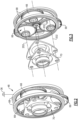
Figure 2 is an enlarged schematic view an example fan drive gear system embodiment. -
Figure 3 is a partial exploded view of the example fan drive gear system. -
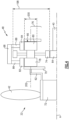
Figure 4 is a schematic view of an example fan drive gear system. -
Figure 5 is a schematic view of an example compound intermediate gear embodiment. -
Figure 6 is a schematic view of an example compound intermediate gear and ring gear assembly embodiment. -
Figure 7 is a schematic view of an example journal bearing for supporting rotation of the example compound intermediate gear. -
Figure 8 is a schematic view of another example journal bearing for supporting rotation of the example compound intermediate gear. -
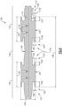
Figure 9 is a cross-sectional of an yet another example journal bearing embodiment. -
Figure 10 is a cross-sectional view of still another example journal bearing embodiment. -
Figure 1 schematically illustrates agas turbine engine 20 with an epicyclic fandrive gear system 48 having a compound intermediate gear and an elongated journal bearing. The intermediate gear and elongated journal bearing are supported in a rotatable carrier coupled to afan drive shaft 62 for driving afan section 22. The example fandrive gear system 48 provides high gear ratios and is configured to operate within a limited design space. - The
gas turbine engine 20 is disclosed herein as a two-spool turbofan that generally incorporates afan section 22, acompressor section 24, acombustor section 26 and aturbine section 28. Thefan section 22 drives air along a bypass flow path B in a bypass duct defined within anacelle 18, and also drives air along a core flow path C for compression and communication into thecombustor section 26 then expansion through theturbine section 28. Although depicted as a two-spool turbofan gas turbine engine in the disclosed non-limiting embodiment, it should be understood that the concepts described herein are not limited to use with two-spool turbofans as the teachings may be applied to other types of turbine engines including three-spool architectures, turbofans, turboprop, open rotor configurations and any other gas turbine engine architecture. - The
exemplary engine 20 generally includes alow speed spool 30 and ahigh speed spool 32 mounted for rotation about an engine central longitudinal axis A relative to an enginestatic structure 36 viaseveral bearing systems 38. It should be understood that various bearingsystems 38 at various locations may alternatively or additionally be provided, and the location of bearingsystems 38 may be varied as appropriate to the application. - The
low speed spool 30 generally includes aninner shaft 40 that interconnects, a first (or low)pressure compressor 44 and a first (or low)pressure turbine 46. Theinner shaft 40 is connected to afan section 22 through a speed change mechanism, which in exemplarygas turbine engine 20 is illustrated as the fandrive gear system 48 to drive thefan section 22 at a lower speed than thelow speed spool 30. Thehigh speed spool 32 includes anouter shaft 50 that interconnects a second (or high)pressure compressor 52 and a second (or high)pressure turbine 54. Thelow pressure turbine 46 includes a plurality ofturbine rotors 34. Acombustor 56 is arranged inexemplary gas turbine 20 between thehigh pressure compressor 52 and thehigh pressure turbine 54. Amid-turbine frame 58 of the enginestatic structure 36 may be arranged generally between thehigh pressure turbine 54 and thelow pressure turbine 46. Themid-turbine frame 58 furthersupports bearing systems 38 in theturbine section 28. Theinner shaft 40 and theouter shaft 50 are concentric and rotate via bearingsystems 38 about the engine central longitudinal axis A which is collinear with their longitudinal axes. - The core airflow is compressed by the
low pressure compressor 44 then thehigh pressure compressor 52, mixed and burned with fuel in thecombustor 56, then expanded over thehigh pressure turbine 54 andlow pressure turbine 46. Themid-turbine frame 58 includesairfoils 60 which are in the core airflow path C. Theturbines low speed spool 30 andhigh speed spool 32 in response to the expansion. It will be appreciated that each of the positions of thefan section 22,compressor section 24,combustor section 26,turbine section 28, and fandrive gear system 48 may be varied. For example, the fandrive gear system 48 may be located aft of thelow pressure compressor 44, or aft of thecombustor section 26 or even aft ofturbine section 28, andfan section 22 may be positioned forward or aft of the fandrive gear system 48. - The
engine 20 in one example is a high-bypass geared aircraft engine. theexample engine 20 includes a bypass ratio greater than 20, with an example embodiment being greater than 32 and less than 72. - The fan
drive gear system 48 is an epicycle gear train with a gear reduction ratio of greater than about 5:1 and less than about 18:1. In another example embodiment, the fandrive gear system 48 provides a gear reduction ratio of between 8:1 and 13.5:1. Thegear system 48 is coupled to thefan shaft 62 to drive thefan section 22 about the engine axis A. It should be understood, however, that the above parameters are only exemplary of one embodiment of a geared engine architecture and that the present disclosure is applicable to other gas turbine engine architectures including turbofan, turboshaft and open rotor engines. - Referring to
Figures 2 and 3 with continued reference toFigure 1 , the example fandrive gear system 48 is an epicyclic gear system with asun gear 64 engaged to a plurality of compoundintermediate gears 66 supported by a rotatingcarrier 70. Aring gear assembly 68 circumscribes theintermediate gears 70 and is fixed to astatic engine structure 36. - The intermediate gears 66, also referred to as planet gears, are compound gears that have two or more gear interfaces of different sizes that are fixed together and rotate at a common speed. In one disclosed example, three (3)
intermediate gears 66 are supported by thecarrier 70 and rotate about a corresponding one ofaxes 202. Each of theintermediate gears 66 include a gear interface with thesun gear 64 and a gear interface with the fixedring gear assembly 68. - Referring to
Figure 4 , theexample gear system 48 is shown in a simplified schematic view that illustrates gear interfaces with a single compoundintermediate gear 66. The example compoundintermediate gear 66 includes afirst gear portion 74 and asecond gear portion 76. Thefirst gear portion 74 is engaged to thesun gear 64. In the illustrated example, thesun gear 64 is driven by theinner shaft 40 that is coupled to theLPT 46. Although theinner shaft 40 is shown by way of example as the driving input, other engine shafts could be coupled to thesun gear 64 to provide the driving input. - The
first gear portion 74 includes afirst diameter 198 and thesecond gear portion 76 includes a smallersecond diameter 200. Thefirst diameter 198 and thesecond diameter 200 represent relative diameters that are tailored to provide a desired gear reduction through the gear system. Moreover, gears have several different diameters that are utilized for different purposes and reflect different gear geometric portions. Accordingly, theexample diameters - The
second gear portion 76 includes aforward gear portion 78 and anaft gear portion 80. Thesecond gear portion 76 is split to enable a larger overallgear face width 90 to accommodate torque transmitted through theintermediate gear 66. The forward andaft gear portions ring assembly 68. Thering assembly 68 includes aforward ring gear 82 and anaft ring gear 84 that are each engaged to a corresponding part of thesecond gear portion 76. Theforward ring gear 82 and theaft ring gear 84 are supported by a corresponding one of aforward web portion 86 and anaft web portion 88. - The compound
intermediate gear 66 is supported by thecarrier 70. Thecarrier 70 is coupled to thefan shaft 62. Thefan shaft 62 is coupled to afan hub 72 that supports the plurality offan blades 42. The specific structure of thefan section 22 may differ from the disclosed example and remain within the scope and contemplation of this disclosure. - Referring to
Figure 5 , the compoundintermediate gear 66 include aweb portion 91 that supports thefirst gear portion 74 between theforward gear portion 78 and theaft gear portion 80. Theweb portion 91 includes awidth 92 and is spaced adistance 94 apart from either of theforward gear portion 78 and theaft gear portion 80. Thewidth 92 anddistance 94 provide for manufacture of gear teeth, schematically indicated at 93, for theentire face width 90 of each of the forward andaft gear portions - The example compound
intermediate gear 66 is a one-piece part with integrally formedgear portions - The
distance 94 provides a clearance space for a rotating tool to form gear teeth schematically shown at 93 along the entire face width. Thespecific distance 94 andwidth 92 is tailored to gear specific configurations for a specific gear system configuration. In one disclosed example embodiment, theclearance 94 is between about 0.75 inches (19.1 mm) and 1.50 inches (38.1 mm). In another example embodiment, theclearance 94 is between about 0.80 inches (20.3 mm) and 1.25 inches (31.8 mm). In still another example embodiment, theclearance 94 is greater than about 0.80 inches (20.3 mm). Although specific clearances are provided by way of example, other clearances may be utilized depending on manufacturing processes utilized for fabrication of theintermediate gear 66. - In one example embodiment, the
axial width 92 of theweb portion 91 is between 10% and 25% of theaxial face width 74. In another example embodiment, theaxial width 92 is about 15% of theaxial face width 74. Although specific proportions are disclosed by way of example, other relative proportions could be utilized and are within the contemplation of this disclosure. - Referring to
Figure 6 with continued reference toFigure 5 , thering gear assembly 68 includesring gear portions distance 98 from thefirst gear portion 74. Thewebs width 96 and support the corresponding forwardring gear portion 82 and an aftring gear portion 84. Thedistance 98 defines a minimum clearance between portions of the fixedring gear assembly 68 and the rotatingintermediate gear 66. Thedistance 98 may be between 0.08 and 0.18 inches (between 2.03 and 4.57 mm). In still another example embodiment, theclearance 98 is greater than about 0.80 inches. Although an example clearance is disclosed, other distances may be utilized to accommodate application specific requirements and fabrication processes. In one disclosed example embodiment, the two sides of thering gear assembly 68 are connected; however, the examplering gear assembly 68 may include separate portions. Moreover, in one example embodiment, eachring gear portion static structure 36 and not directly connected to each other. - The forward
ring gear portion 82 and the aftring gear portion 84 each includes aface width 81 that is proportional to theaxial width 90 of the forward and aft gear portions of theintermediate gear 66. In one disclosed embodiment, thewidth 96 is between 10% and 25% of theface width 81. In another example embodiment thewidth 96 is about 15% of theface width 81.Face width 81 is between 80% and 100% ofFace width 90 in one embodiment, and between 85% and 95% offace width 90 in another embodiment. - Referring to
Figure 7 , anintermediate gear 66 is shown with an example journal bearing 100. Thejournal bearing 100 includes anelongated length 104 to accommodate the increased axial width of theintermediate gear 66. The journal bearing 100 further includes anouter diameter 102 that corresponds to abearing surface 101. The increasedlength 104 is reflected as a ratio between thelength 104 and theouter diameter 102. In one example embodiment, a ratio of thelength 104 to theouter diameter 102 is between 1.5 and 6. In another example embodiment, the ratio of thelength 104 to theouter diameter 102 is between 2 and 4. - The
journal bearing 100 is illustrated as a one-piece part with features for supporting corresponding forward andaft gear portions intermediate gear 66. The example journal bearing 100 includes aforward portion 108, anaft portion 110 and amiddle portion 112. The forward andaft portions aft gear portion journal bearing 100 includes amain lubricant passage 114 andradial lubricant passages 116 arranged to communicate a lubricant flow to rotating interfaces.Outlets 118 through theintermediate gear 66 for exhausting lubricant flow. In the disclosed example, theoutlets 118 are provided between theweb 91 and one of the forward andaft gear portions - The forward and
aft portions bearing surface 101 with alength 106. Thelength 106 corresponds with thewidth 90 of each of the forward andaft gear portions portions outer undercuts 120 andinner undercuts 122. The outer andinner undercuts journal bearing 100. - The
middle portion 112 of the example journal bearing 100 includes a reducedouter diameter 103 as compared to theouter diameter 102 of the bearing surfaces 101. The bearing surfaces 101 in this example are spaced apart from the inner gear surface that corresponds with thefirst gear portion 74. In one example embodiment, theintermediate gear 66 may provide sufficient stiffness for loads on thefirst gear portion 74 so as to not require support by thejournal bearing 100. - Referring to
Figure 8 , another example journal bearing 124 is shown with forward andaft portions bearing surface 125 of alength 126. Thelength 126 extends inwardly to support thefirst gear portion 74. Themiddle portion 134 is smaller with the wider forward andaft portions surface 125. - In one disclosed example embodiment, the
forward portion 130 and theaft portion 132 includes agear bearing surface 125 with theaxial width 126 greater than theaxial face width 90 of the corresponding one of theforward gear portion 78 and theaft gear portion 80. - The
journal bearing 124 includes the samemain lubricant passage 114 that suppliesradial passages 116.Outlets 128 are provided on either side of theweb 91 and are located further inward to accommodate the increased length of the bearingsurface 126. The example journal bearing 124 maintains the increasedlength 104 relative to thediameter 102 of the bearingsurface 126. - Referring to
Figure 9 another journal bearing 136 is shown that illustrates different undercut configuration embodiments. The example journal bearing 136 includes amiddle portion 146 with a smallerouter diameter 148 than theouter diameter 140 of the bearing surfaces 135. Thelength 138 andouter diameter 140 are related by the previously disclosed ratios. Themain lubricant passage 114 andradial lubricant passage 116 are shown and provided lubricant to the bearing surfaces 135. - The configuration of the undercuts is tailored to generate a desired stiffness of the journal bearing 136 to accommodate loads. Moreover, although the previous disclosed and described
journal bearings intermediate gear 66. - The example journal bearing 136 illustrates various different geometries for undercuts that may be utilized to tailor stiffness of the bearing surfaces 135 to accommodate operational gear loads. The example undercut 150 includes a
thickness 158 and length 160 that is formed by the removal of material to define a gap. Thethickness 158 and length 160 are tailored to define a stiffness of thejournal bearing 136. Theundercut lengths surface length 126. In one example embodiment, the ratio of bearingsurface length 126 to a single undercutlength surface length 126 to undercutlength - The undercut 152 is shown with a
length 162 that is smaller than that of the undercut 150. The undercut 152 further includes a thickness 164 that is substantially the same as that of the undercut 150. The change in length of the undercut 152 increases stiffness of the bearingsurface 135. - Another example undercut 154 includes a
length 166 and thickness 168. In this example undercut 154, thickness 168 is increased over the undercut 150 to provide the desired modification to stiffness. Thelength 166 may be the same as the length 160 but the undercut 154 provides an increase in stiffness due to the increased thickness 168. - Another example undercut 156 is illustrated with an increased
radius cutout area 174. The undercut 156 includes a thickness 172 andlength 170 that are substantially the same as the undercut 150. However, the increasedradius cutout area 174 provides a different stiffness. - In one disclosed example, each of the
forward portion 142 and theaft portion 144 include an outer undercut 151 and an inner undercut 153. The outer undercuts 151 face axially outward and theinner undercuts 153 face axially inward toward themiddle portion 146. Theaxial lengths inner undercuts 153 are different than theaxial lengths 160, 170 of at least one of the outer undercuts 151. - In another disclosed example embodiment, each of the
forward portion 142 and theaft portion 144, a radial thickness 164, 168 of at least one of theinner undercuts 153 is different than theradial thickness 158, 172 of at least one of the outer undercuts 151. - Several example cutout configurations are shown by way of example, however other combination of thickness, length and radial cutout area could be implemented to adjust stiffness to accommodate application specific gear loads. Moreover, although each of the thickness, length, and radial cutout areas are shown as symmetric about a rotational axis, each feature may be asymmetric about the rotational axis Such other combinations are within the contemplation and scope of this disclosure.
- Referring to
Figure 10 , another example journal bearing 176 is shown that includes aforward portion 178, anaft portion 180 and amiddle portion 182. The examplemiddle portion 182 includes acenter support area 184 with anouter diameter 185. Theouter diameter 185 may be the same or substantially the same asouter diameter 175 of bearing surfaces 194. Thecenter support area 184 includes acenter bearing surface 196. Thecenter bearing surface 196 provides support for the first gear portion of the compoundintermediate gear 66. Thecenter bearing surface 196 may also be utilized to adjust overall stiffness. - The
journal bearing 176 includesouter undercuts 186 andinner undercuts 188. The outer undercuts 186 open outward toward ends of thejournal bearing 176. The inner undercuts 188 open inward toward themiddle area 182 and each other. - In one disclosed example journal bearing 176, each of the
forward portion 178 and theaft portion 180 include an outer undercut 186 and an inner undercut 188. The outer undercut 188 faces axially outward and the inner undercut 188 faces axially inward toward themiddle portion 182. The example outer undercut 186 and the example inner undercut 186 have equalaxial lengths 187 and equal radial thicknesses 189. - The example
outer undercuts 186 andinner undercuts 188 are configured the same. However, theouter undercuts 186 and theinner undercuts 188 may be configured differently to accommodate localized loading and remain within the scope and contemplation of this disclosure. Themiddle Section 184 may also have undercuts similar to 186, 188 in order to modify stiffness. Themiddle section 184 may also include radial lubricant passages similar to 192 if thesurface 196 is utilized as a bearing surface. - Accordingly, the example compound intermediate gear and example journal bearings includes features that accommodate increased gear loading within a limited design space.
- Although an example embodiment has been disclosed, a worker of ordinary skill in this art would recognize that certain modifications would come within the scope of this disclosure. For that reason, the following claims should be studied to determine the scope and content of this disclosure.
Claims (15)
- A fan drive gear system (48) for a turbine engine (20), the fan drive gear system (48) comprising:a sun gear (64) configured to be driven by an engine shaft (40) rotatable about an axis (A);a plurality of compound intermediate gears (66), wherein each of the plurality of compound intermediate gears (66) includes a first gear portion (74) and a second gear portion (76), wherein the second gear portion (76) comprises a forward gear portion (78) and an aft gear portion (80);a ring gear assembly (68) including a forward ring gear (82) engaged to the forward gear portion (78) and an aft ring gear (84) engaged to the aft gear portion (80);a carrier (70) supporting rotation of the plurality of compound intermediate gears (66); anda plurality of journal bearings (100; 124; 136; 176) corresponding with the plurality of compound intermediate gears (66), wherein each of the plurality of journal bearings (100; 124; 136; 176) comprises a ratio of a journal length (104) to a journal diameter (102) that is between 1.5 and 6.
- The fan drive gear system (48) as recited in claim 1, wherein the ring gear assembly (68) is configured to be fixed to a static engine structure (36) and the carrier (70) is rotatable about the axis (A).
- The fan drive gear system (48) as recited in claim 1 or 2, wherein the ring gear assembly (68) includes a forward web portion (86) supporting the forward ring gear (82) and an aft web portion (88) supporting the aft ring gear (84) and each of the forward web portion (86) and the aft web portion (88) include an axial width (96) that is between 10% and 25% of an axial width (81) of each of the forward ring gear (82) and the aft ring gear (84).
- The fan drive gear system (48) as recited in claim 1, 2 or 3, wherein an axial clearance (98) between the first gear portion (74) and each of the forward ring gear (82) and the aft ring gear (84) is greater than about 0.08 inches (2.03 mm).
- The fan drive gear system (48) as recited in any preceding claim, wherein each of the plurality of journal bearings (100;124;136;176) includes a forward portion (108;130;142;178) supporting the forward gear portion (78), an aft portion (110;132;144;180) supporting the aft gear portion (80), and a middle portion (112;134;146;182).
- The fan drive gear system (48) as recited in claim 5, wherein each of the plurality of compound intermediate gears (66) include at least one lubricant exhaust opening (118; 128) between the forward gear portion (78) and the aft gear portion (80).
- The fan drive gear system (48) as recited in claim 5 or 6, wherein each of the forward portion (108) and the aft portion (110) includes a gear bearing surface (101) with an axial width (106) matching an axial width (90) of a corresponding one of the forward gear portion (78) and the aft gear portion (80).
- The fan drive gear system (48) as recited in claim 5 or 6, wherein each of the forward portion (130) and the aft portion (132) includes a gear bearing surface (125) with an axial width (126) greater than an axial width (90) of the corresponding one of the forward gear portion (78) and the aft gear portion (80).
- The fan drive gear system (48) as recited in any of claims 5 to 8, wherein each of the forward portion (108;130;178) and the aft portion (110;132;180) include an outer undercut (120;186) and an inner undercut (122;188), the outer undercut (120;186) facing axially outward and the inner undercut (122;188) facing axially inward toward the middle portion (112;182), wherein the outer undercut (120;186) and the inner undercut (122;188) have equal axial lengths (187).
- The fan drive gear system (48) as recited in any of claims 5 to 8, wherein each of the forward portion (108;130;142) and the aft portion (110;132;144) include an outer undercut (151) and an inner undercut (153), the outer undercut (151) facing axially outward and the inner undercut (153) facing axially inward toward the middle portion (146), wherein an axial length (162,166) of the inner undercut (153) is different than an axial length (160,170) of the outer undercut (151).
- The fan drive gear system (48) as recited in any of claims 5 to 10, wherein:each of the forward portion (142) and the aft portion (144) include an outer undercut (156) and an inner undercut (154), the outer undercut (156) facing axially outward and the inner undercut (154) facing axially inward toward the middle portion (146), wherein a radial thickness (168) of the inner undercut (154) is different than a radial thickness (172) of the outer undercut (156); oreach of the forward portion (142) and the aft portion (144) include an outer undercut (150) and an inner undercut (152), the outer undercut (150) facing axially outward and the inner undercut (152) facing axially inward toward the middle portion (146), wherein a radial thickness (164) of the inner undercut (152) and a radial thickness (158) of the outer undercut (150) are the same.
- The fan drive gear system (48) as recited in any of claims 5 to 11, wherein the middle portion (182) includes a bearing surface (196) supporting the first gear portion (74).
- The fan drive gear system (48) as recited in any of claims 5 to 12, wherein the middle portion (112;146) includes an outer diameter (103;148) that is less than an outer diameter (102;140) of each of the forward portion (108;142) and the aft portion (110; 144).
- The fan drive gear system (48) as recited in any preceding claim, wherein each of the plurality of journal bearings (100; 124; 136; 176) includes lubricant supply holes (116; 192) that are configured to transfer lubricant to an interface with an inner surface of a corresponding one of the plurality of compound intermediate gears (66).
- A turbine engine assembly comprising:a static engine structure (36);a fan section (22) including a plurality of blades (42) rotatable about an axis (A);the fan drive gear system (48) of any preceding claim; anda fan drive shaft (62) coupled to the carrier (70).
Applications Claiming Priority (1)
| Application Number | Priority Date | Filing Date | Title |
|---|---|---|---|
| US18/446,088 US12429000B2 (en) | 2023-08-08 | 2023-08-08 | Elongated journal bearing for high gear ratio epicyclic fan drive gear system |
Publications (1)
| Publication Number | Publication Date |
|---|---|
| EP4506556A1 true EP4506556A1 (en) | 2025-02-12 |
Family
ID=92214111
Family Applications (1)
| Application Number | Title | Priority Date | Filing Date |
|---|---|---|---|
| EP24192933.0A Pending EP4506556A1 (en) | 2023-08-08 | 2024-08-05 | Elongated journal bearing for high gear ratio epicyclic fan drive gear system |
Country Status (2)
| Country | Link |
|---|---|
| US (2) | US12429000B2 (en) |
| EP (1) | EP4506556A1 (en) |
Citations (3)
| Publication number | Priority date | Publication date | Assignee | Title |
|---|---|---|---|---|
| US20190360356A1 (en) * | 2018-05-25 | 2019-11-28 | Pratt & Whitney Canada Corp. | Planetary gearbox having compliant journal bearings |
| US20200300340A1 (en) * | 2019-03-21 | 2020-09-24 | Pratt & Whitney Canada Corp. | Aircraft engine reduction gearbox |
| US20220145806A1 (en) * | 2020-11-12 | 2022-05-12 | Safran Transmission Systems | Mechanical reduction gear for an aircraft turbomachine |
Family Cites Families (11)
| Publication number | Priority date | Publication date | Assignee | Title |
|---|---|---|---|---|
| US5102379A (en) * | 1991-03-25 | 1992-04-07 | United Technologies Corporation | Journal bearing arrangement |
| US6017184A (en) | 1997-08-06 | 2000-01-25 | Allied Signal Inc. | Turbocharger integrated bearing system |
| US6964155B2 (en) * | 2002-12-30 | 2005-11-15 | United Technologies Corporation | Turbofan engine comprising an spicyclic transmission having bearing journals |
| US9732800B2 (en) | 2015-04-01 | 2017-08-15 | GM Global Technology Operations LLC | Turbocharger journal bearing system |
| US12060837B2 (en) * | 2017-02-10 | 2024-08-13 | Pratt & Whitney Canada Corp. | Reduction gearbox for gas turbine engine |
| FR3071025B1 (en) * | 2017-09-12 | 2021-02-12 | Safran Trans Systems | PIVOT FOR SLIDING BEARINGS AND REDUCED THERMAL STRESS GEAR TRAIN |
| FR3095251B1 (en) * | 2019-04-16 | 2021-05-07 | Safran Trans Systems | AIRCRAFT TURBOMACHINE MECHANICAL REDUCER |
| US11592103B2 (en) * | 2020-01-30 | 2023-02-28 | Pratt & Whitney Canada Corp. | Compliant journal bearing shaft assembly |
| US11209045B2 (en) * | 2020-02-14 | 2021-12-28 | Pratt & Whitney Canada Corp. | Dual land journal bearings for a compound planetary system |
| US11821364B2 (en) * | 2021-08-20 | 2023-11-21 | Pratt & Whitney Canada Corp. | Shaped cavity at interface between journal bearing and rotor |
| US12084981B2 (en) * | 2022-03-29 | 2024-09-10 | Pratt & Whitney Canada Corp. | Journal bearing with oil pocket |
-
2023
- 2023-08-08 US US18/446,088 patent/US12429000B2/en active Active
-
2024
- 2024-08-05 EP EP24192933.0A patent/EP4506556A1/en active Pending
-
2025
- 2025-08-26 US US19/310,153 patent/US20250376952A1/en active Pending
Patent Citations (3)
| Publication number | Priority date | Publication date | Assignee | Title |
|---|---|---|---|---|
| US20190360356A1 (en) * | 2018-05-25 | 2019-11-28 | Pratt & Whitney Canada Corp. | Planetary gearbox having compliant journal bearings |
| US20200300340A1 (en) * | 2019-03-21 | 2020-09-24 | Pratt & Whitney Canada Corp. | Aircraft engine reduction gearbox |
| US20220145806A1 (en) * | 2020-11-12 | 2022-05-12 | Safran Transmission Systems | Mechanical reduction gear for an aircraft turbomachine |
Also Published As
| Publication number | Publication date |
|---|---|
| US20250052202A1 (en) | 2025-02-13 |
| US12429000B2 (en) | 2025-09-30 |
| US20250376952A1 (en) | 2025-12-11 |
Similar Documents
| Publication | Publication Date | Title |
|---|---|---|
| US11635043B2 (en) | Geared architecture for high speed and small volume fan drive turbine | |
| US11946540B2 (en) | Geared architecture gas turbine engine with planetary gear oil scavenge | |
| US9267389B2 (en) | Geared architecture carrier torque frame assembly | |
| US9546560B2 (en) | Compact double grounded mechanical carbon seal | |
| US10605112B2 (en) | Fan drive gear system spline oil lubrication scheme | |
| US20230235715A1 (en) | Geared architecture for high speed and small volume fan drive turbine | |
| EP3825532B1 (en) | Geared architecture for gas turbine engine | |
| EP3036420B1 (en) | Load balanced journal bearing pin | |
| US10533522B2 (en) | Load balanced journal bearing pin | |
| US12428970B2 (en) | Radial lift seal | |
| EP3825575B1 (en) | Geared architecture for gas turbine engine | |
| US12429000B2 (en) | Elongated journal bearing for high gear ratio epicyclic fan drive gear system | |
| US20240280164A1 (en) | Gearbox assembly | |
| US12110963B2 (en) | Gearbox assembly | |
| US10145264B2 (en) | Variable vane actuation system |
Legal Events
| Date | Code | Title | Description |
|---|---|---|---|
| PUAI | Public reference made under article 153(3) epc to a published international application that has entered the european phase |
Free format text: ORIGINAL CODE: 0009012 |
|
| STAA | Information on the status of an ep patent application or granted ep patent |
Free format text: STATUS: THE APPLICATION HAS BEEN PUBLISHED |
|
| AK | Designated contracting states |
Kind code of ref document: A1 Designated state(s): AL AT BE BG CH CY CZ DE DK EE ES FI FR GB GR HR HU IE IS IT LI LT LU LV MC ME MK MT NL NO PL PT RO RS SE SI SK SM TR |
|
| STAA | Information on the status of an ep patent application or granted ep patent |
Free format text: STATUS: REQUEST FOR EXAMINATION WAS MADE |
|
| 17P | Request for examination filed |
Effective date: 20250804 |