EP4506551A1 - Engine brake method for operating a vehicle with a turbocharged internal combustion engine and associated vehicle - Google Patents
Engine brake method for operating a vehicle with a turbocharged internal combustion engine and associated vehicle Download PDFInfo
- Publication number
- EP4506551A1 EP4506551A1 EP23191108.2A EP23191108A EP4506551A1 EP 4506551 A1 EP4506551 A1 EP 4506551A1 EP 23191108 A EP23191108 A EP 23191108A EP 4506551 A1 EP4506551 A1 EP 4506551A1
- Authority
- EP
- European Patent Office
- Prior art keywords
- exhaust
- engine
- pressure
- air
- boost pressure
- Prior art date
- Legal status (The legal status is an assumption and is not a legal conclusion. Google has not performed a legal analysis and makes no representation as to the accuracy of the status listed.)
- Pending
Links
Images


Classifications
-
- F—MECHANICAL ENGINEERING; LIGHTING; HEATING; WEAPONS; BLASTING
- F02—COMBUSTION ENGINES; HOT-GAS OR COMBUSTION-PRODUCT ENGINE PLANTS
- F02D—CONTROLLING COMBUSTION ENGINES
- F02D23/00—Controlling engines characterised by their being supercharged
- F02D23/005—Controlling engines characterised by their being supercharged with the supercharger being mechanically driven by the engine
-
- F—MECHANICAL ENGINEERING; LIGHTING; HEATING; WEAPONS; BLASTING
- F02—COMBUSTION ENGINES; HOT-GAS OR COMBUSTION-PRODUCT ENGINE PLANTS
- F02D—CONTROLLING COMBUSTION ENGINES
- F02D13/00—Controlling the engine output power by varying inlet or exhaust valve operating characteristics, e.g. timing
- F02D13/02—Controlling the engine output power by varying inlet or exhaust valve operating characteristics, e.g. timing during engine operation
- F02D13/04—Controlling the engine output power by varying inlet or exhaust valve operating characteristics, e.g. timing during engine operation using engine as brake
-
- F—MECHANICAL ENGINEERING; LIGHTING; HEATING; WEAPONS; BLASTING
- F02—COMBUSTION ENGINES; HOT-GAS OR COMBUSTION-PRODUCT ENGINE PLANTS
- F02D—CONTROLLING COMBUSTION ENGINES
- F02D9/00—Controlling engines by throttling air or fuel-and-air induction conduits or exhaust conduits
- F02D9/02—Controlling engines by throttling air or fuel-and-air induction conduits or exhaust conduits concerning induction conduits
-
- F—MECHANICAL ENGINEERING; LIGHTING; HEATING; WEAPONS; BLASTING
- F01—MACHINES OR ENGINES IN GENERAL; ENGINE PLANTS IN GENERAL; STEAM ENGINES
- F01L—CYCLICALLY OPERATING VALVES FOR MACHINES OR ENGINES
- F01L13/00—Modifications of valve-gear to facilitate reversing, braking, starting, changing compression ratio, or other specific operations
- F01L13/06—Modifications of valve-gear to facilitate reversing, braking, starting, changing compression ratio, or other specific operations for braking
- F01L13/065—Compression release engine retarders of the "Jacobs Manufacturing" type
-
- F—MECHANICAL ENGINEERING; LIGHTING; HEATING; WEAPONS; BLASTING
- F02—COMBUSTION ENGINES; HOT-GAS OR COMBUSTION-PRODUCT ENGINE PLANTS
- F02B—INTERNAL-COMBUSTION PISTON ENGINES; COMBUSTION ENGINES IN GENERAL
- F02B37/00—Engines characterised by provision of pumps driven at least for part of the time by exhaust
- F02B37/12—Control of the pumps
- F02B37/18—Control of the pumps by bypassing exhaust from the inlet to the outlet of turbine or to the atmosphere
-
- F—MECHANICAL ENGINEERING; LIGHTING; HEATING; WEAPONS; BLASTING
- F02—COMBUSTION ENGINES; HOT-GAS OR COMBUSTION-PRODUCT ENGINE PLANTS
- F02B—INTERNAL-COMBUSTION PISTON ENGINES; COMBUSTION ENGINES IN GENERAL
- F02B37/00—Engines characterised by provision of pumps driven at least for part of the time by exhaust
- F02B37/12—Control of the pumps
- F02B37/22—Control of the pumps by varying cross-section of exhaust passages or air passages, e.g. by throttling turbine inlets or outlets or by varying effective number of guide conduits
-
- F—MECHANICAL ENGINEERING; LIGHTING; HEATING; WEAPONS; BLASTING
- F02—COMBUSTION ENGINES; HOT-GAS OR COMBUSTION-PRODUCT ENGINE PLANTS
- F02D—CONTROLLING COMBUSTION ENGINES
- F02D13/00—Controlling the engine output power by varying inlet or exhaust valve operating characteristics, e.g. timing
- F02D13/02—Controlling the engine output power by varying inlet or exhaust valve operating characteristics, e.g. timing during engine operation
- F02D13/0276—Actuation of an additional valve for a special application, e.g. for decompression, exhaust gas recirculation or cylinder scavenging
-
- F—MECHANICAL ENGINEERING; LIGHTING; HEATING; WEAPONS; BLASTING
- F02—COMBUSTION ENGINES; HOT-GAS OR COMBUSTION-PRODUCT ENGINE PLANTS
- F02D—CONTROLLING COMBUSTION ENGINES
- F02D35/00—Controlling engines, dependent on conditions exterior or interior to engines, not otherwise provided for
- F02D35/02—Controlling engines, dependent on conditions exterior or interior to engines, not otherwise provided for on interior conditions
- F02D35/023—Controlling engines, dependent on conditions exterior or interior to engines, not otherwise provided for on interior conditions by determining the cylinder pressure
-
- F—MECHANICAL ENGINEERING; LIGHTING; HEATING; WEAPONS; BLASTING
- F02—COMBUSTION ENGINES; HOT-GAS OR COMBUSTION-PRODUCT ENGINE PLANTS
- F02D—CONTROLLING COMBUSTION ENGINES
- F02D41/00—Electrical control of supply of combustible mixture or its constituents
- F02D41/0002—Controlling intake air
- F02D41/0005—Controlling intake air during deceleration
-
- F—MECHANICAL ENGINEERING; LIGHTING; HEATING; WEAPONS; BLASTING
- F02—COMBUSTION ENGINES; HOT-GAS OR COMBUSTION-PRODUCT ENGINE PLANTS
- F02D—CONTROLLING COMBUSTION ENGINES
- F02D41/00—Electrical control of supply of combustible mixture or its constituents
- F02D41/0002—Controlling intake air
- F02D41/0007—Controlling intake air for control of turbo-charged or super-charged engines
-
- F—MECHANICAL ENGINEERING; LIGHTING; HEATING; WEAPONS; BLASTING
- F02—COMBUSTION ENGINES; HOT-GAS OR COMBUSTION-PRODUCT ENGINE PLANTS
- F02D—CONTROLLING COMBUSTION ENGINES
- F02D41/00—Electrical control of supply of combustible mixture or its constituents
- F02D41/02—Circuit arrangements for generating control signals
- F02D41/04—Introducing corrections for particular operating conditions
- F02D41/042—Introducing corrections for particular operating conditions for stopping the engine
-
- F—MECHANICAL ENGINEERING; LIGHTING; HEATING; WEAPONS; BLASTING
- F02—COMBUSTION ENGINES; HOT-GAS OR COMBUSTION-PRODUCT ENGINE PLANTS
- F02D—CONTROLLING COMBUSTION ENGINES
- F02D41/00—Electrical control of supply of combustible mixture or its constituents
- F02D41/02—Circuit arrangements for generating control signals
- F02D41/04—Introducing corrections for particular operating conditions
- F02D41/12—Introducing corrections for particular operating conditions for deceleration
-
- F—MECHANICAL ENGINEERING; LIGHTING; HEATING; WEAPONS; BLASTING
- F02—COMBUSTION ENGINES; HOT-GAS OR COMBUSTION-PRODUCT ENGINE PLANTS
- F02D—CONTROLLING COMBUSTION ENGINES
- F02D41/00—Electrical control of supply of combustible mixture or its constituents
- F02D41/02—Circuit arrangements for generating control signals
- F02D41/14—Introducing closed-loop corrections
- F02D41/1401—Introducing closed-loop corrections characterised by the control or regulation method
-
- F—MECHANICAL ENGINEERING; LIGHTING; HEATING; WEAPONS; BLASTING
- F02—COMBUSTION ENGINES; HOT-GAS OR COMBUSTION-PRODUCT ENGINE PLANTS
- F02D—CONTROLLING COMBUSTION ENGINES
- F02D41/00—Electrical control of supply of combustible mixture or its constituents
- F02D41/02—Circuit arrangements for generating control signals
- F02D41/14—Introducing closed-loop corrections
- F02D41/1438—Introducing closed-loop corrections using means for determining characteristics of the combustion gases; Sensors therefor
- F02D41/1439—Introducing closed-loop corrections using means for determining characteristics of the combustion gases; Sensors therefor characterised by the position of the sensor
- F02D41/1441—Plural sensors
-
- F—MECHANICAL ENGINEERING; LIGHTING; HEATING; WEAPONS; BLASTING
- F02—COMBUSTION ENGINES; HOT-GAS OR COMBUSTION-PRODUCT ENGINE PLANTS
- F02D—CONTROLLING COMBUSTION ENGINES
- F02D41/00—Electrical control of supply of combustible mixture or its constituents
- F02D41/02—Circuit arrangements for generating control signals
- F02D41/14—Introducing closed-loop corrections
- F02D41/1438—Introducing closed-loop corrections using means for determining characteristics of the combustion gases; Sensors therefor
- F02D41/1444—Introducing closed-loop corrections using means for determining characteristics of the combustion gases; Sensors therefor characterised by the characteristics of the combustion gases
- F02D41/1448—Introducing closed-loop corrections using means for determining characteristics of the combustion gases; Sensors therefor characterised by the characteristics of the combustion gases the characteristics being an exhaust gas pressure
-
- F—MECHANICAL ENGINEERING; LIGHTING; HEATING; WEAPONS; BLASTING
- F02—COMBUSTION ENGINES; HOT-GAS OR COMBUSTION-PRODUCT ENGINE PLANTS
- F02D—CONTROLLING COMBUSTION ENGINES
- F02D9/00—Controlling engines by throttling air or fuel-and-air induction conduits or exhaust conduits
- F02D9/04—Controlling engines by throttling air or fuel-and-air induction conduits or exhaust conduits concerning exhaust conduits
- F02D9/06—Exhaust brakes
-
- F—MECHANICAL ENGINEERING; LIGHTING; HEATING; WEAPONS; BLASTING
- F02—COMBUSTION ENGINES; HOT-GAS OR COMBUSTION-PRODUCT ENGINE PLANTS
- F02D—CONTROLLING COMBUSTION ENGINES
- F02D9/00—Controlling engines by throttling air or fuel-and-air induction conduits or exhaust conduits
- F02D9/02—Controlling engines by throttling air or fuel-and-air induction conduits or exhaust conduits concerning induction conduits
- F02D2009/0201—Arrangements; Control features; Details thereof
- F02D2009/0242—Increasing exhaust brake effect
-
- F—MECHANICAL ENGINEERING; LIGHTING; HEATING; WEAPONS; BLASTING
- F02—COMBUSTION ENGINES; HOT-GAS OR COMBUSTION-PRODUCT ENGINE PLANTS
- F02D—CONTROLLING COMBUSTION ENGINES
- F02D41/00—Electrical control of supply of combustible mixture or its constituents
- F02D41/0002—Controlling intake air
- F02D2041/0022—Controlling intake air for diesel engines by throttle control
-
- F—MECHANICAL ENGINEERING; LIGHTING; HEATING; WEAPONS; BLASTING
- F02—COMBUSTION ENGINES; HOT-GAS OR COMBUSTION-PRODUCT ENGINE PLANTS
- F02D—CONTROLLING COMBUSTION ENGINES
- F02D2200/00—Input parameters for engine control
- F02D2200/02—Input parameters for engine control the parameters being related to the engine
- F02D2200/04—Engine intake system parameters
- F02D2200/0406—Intake manifold pressure
Definitions
- the disclosure relates generally to engine brake for turbocharged engine vehicles.
- the disclosure relates to an engine brake method for operating a vehicle with a turbocharged internal combustion engine and to a vehicle configured to implement such an engine brake method.
- the disclosure can be applied to heavy-duty vehicles, such as trucks, buses, and construction equipment, among other vehicle types.
- heavy-duty vehicles such as trucks, buses, and construction equipment, among other vehicle types.
- Engine brake is a critical feature for commercial vehicles as it makes it possible to maintain a constant speed downhill for long periods without using the foundation brakes, which is favorable to both safety and drivability.
- Engine brake is typically achieved by using both a compression release system, for example a so-called Jacobs bleeder brake, and an exhaust gas restriction device, for example a proportional flap, which is installed after the turbocharger's turbine and which controls a target air pressure in the exhaust manifold.
- a compression release system for example a so-called Jacobs bleeder brake
- an exhaust gas restriction device for example a proportional flap
- VGT braking an alternative to using the exhaust flap is to control the exhaust back-pressure with the VGT instead: this is known as "VGT braking".
- VGT braking Increasing the exhaust back-pressure with the VGT also increases the air flow at the same time, which benefits to the efficiency of the compression release system.
- braking power is actually not much improved with VGT braking.
- Another drawback of this strategy lies in its slow and sluggish response, up to several seconds, caused by the time it takes to pressurize the whole intake system.
- the invention aims at solving the problems mentioned above, by providing an engine brake method achieving a high braking power output while keeping operating parameters - such as injector cooling - within their specified ranges.
- the invention concerns an engine brake method for operating a vehicle with a turbocharged internal combustion engine.
- the engine comprises:
- the engine brake method comprises a dual phase during which, simultaneously:
- a technical benefit may include increasing both boost pressure and air exhaust pressure, thus resulting in a higher engine brake effect. Simultaneously, the air flow through the cylinders remains at a higher level, contributing to the cooling of the injector tips. Additionally, the pressure differential between boost pressure and air exhaust pressure remains positive, preventing oil leaks through the compressor seal.
- boost pressure and air exhaust pressure remains positive, preventing oil leaks through the compressor seal.
- the engine comprises an intake throttle valve, which is arranged between the turbocharger and the intake manifold and which is configured to control the boost pressure, whereas during the dual phase, the intake throttle valve forms the boost pressure regulation device and regulates the air exhaust pressure in the exhaust manifold in closed loop.
- a technical benefit may include implementing the dual phase by using commonly used equipment.
- the turbocharger is a variable geometry turbocharger, which comprises moveable elements to adjust an output of the turbocharger, whereas during the dual phase, the variable geometry turbocharger forms the boost pressure regulation device and regulates the air exhaust pressure in the exhaust manifold in closed loop.
- a technical benefit may include implementing the dual phase by using commonly used equipment.
- the engine brake method further comprising an initial phase, prior to the dual phase.
- the initial phase comprises a first phase, during which the exhaust air pressure is controlled by the restriction device while the turbocharger is in open loop, so as to let exhaust air pressure to increase up to the first threshold, and a second phase, which follows the first phase and during which, once the exhaust air pressure reaches the first threshold, the restriction device is locked in position, while the turbocharger controls the air exhaust pressure in the exhaust manifold in closed loop, so as to let boost pressure increase up to the second threshold. If, during the second phase, the boost-pressure reaches the second threshold before a pre-determined time period, then the initial phase ends and the dual phase starts.
- a technical benefit may include ensuring a smooth, stable and rapid transition from the motoring mode of the engine to the engine brake mode.
- the engine further comprises bleeder valves, each bleeder valve being associated with a respective cylinder and being configured to, when activated, let compressed air to leak from the cylinders through an opening of the bleeder valve, whereas the engine brake method comprises adjusting an opening of the bleeder valve, in order to maximize a braking effect of the engine during the dual phase.
- a technical benefit may include improving further the engine brake performance of the vehicle.
- the dual phase is engaged when the engine has a speed, given in revolutions per minute, above a pre-determined third threshold.
- a technical benefit may include ensuring a higher engine brake effect compared to prior art methods.
- the invention concerns a vehicle, comprising a turbocharged internal combustion engine.
- vehicle comprising a turbocharged internal combustion engine.
- the vehicle is configured to implement the engine brake method according to any one of preceding claims.
- the engine comprises:
- the second aspect of the disclosure may seek to provide a vehicle, for example a truck, with an improved engine brake capacity.
- a technical benefit may include allowing a higher load on downhill roads and/or allowing speed regulation on steeper downhill roads.
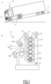
- a vehicle 10 is represented on figure 1a ).
- the vehicle 10 is a road vehicle, in particular a truck, which comprises wheels 11.
- the vehicle 10 comprises an engine 12, which is schematically shown on figure 1b ).
- the engine 12 is an internal combustion engine, which is configured to use fuel in order to drive the wheels 11 in rotation, in order to move the vehicle 10.
- the engine 12 uses fuel to rotate the wheel 10, the engine 12 is in a motoring mode.
- the engine 12 is in an "engine brake" mode, that is to say the engine 12 applies a braking torque to the wheels 11.
- the vehicle 10 is represented on a downhill slope S, where the vehicle 10 tends to naturally accelerate because of gravity.
- the engine 12 is used in the engine brake mode in order to regulate a speed of the vehicle 10.
- the engine 12 comprises a main block 14 with several cylinders 16.
- the engine 12 is a four-stroke engine with six cylinders 16.
- the four strokes include, successively, an intake stroke, a compression stroke, an expansion stroke, and an exhaust stroke.
- Air flowing from the cylinders 16 into the exhaust manifold 22 is also called “exhaust air”. Fresh air flowing from the intake manifold 20 into the cylinders 16 is also called “charge air”.
- the intake manifold 20 is located upstream from the cylinders 16 relative to the normal flow of air in the engine 12, while the exhaust manifold 22 is located downstream from the cylinders 16 relative to the normal flow of air in the engine 12.
- upstream and downstream are considered relatively to the flow of air during normal use of the engine 12.
- Normal use means that the engine 12 is either in the motoring mode, either in the engine brake mode.
- the engine 12 also comprises a turbocharger 30.
- the turbocharger 30 comprises a compressor 32 and a turbine 34, the compressor 32 being linked to the turbine 34 by an axle 36.
- the turbine 34 is configured to be driven in rotation by the exhaust air flowing from the exhaust manifold 22, while the compressor 32 is configured to increase a pressure of the charge air flowing in the intake manifold 20 then into the cylinders 16.
- one of the cylinder 16 comprises a first pressure sensor, here represented figuratively by a manometer, the first pressure sensor being configured to measure air pressure within the cylinder 16.
- the first pressure sensor also referenced PCP, is configured to measure the peak cylinder pressure.
- PCP peak cylinder pressure
- a second pressure sensor P2 represented figuratively by a manometer, is arranged on the intake manifold 20, the second pressure sensor P2 being configured to measure a boost pressure, that is to say an air pressure inside the intake manifold 20.
- boost pressure is also referenced P2.
- exhaust pressure is also referenced P3.
- the engine also comprises an exhaust gas restriction device 40, which is located downstream from the turbine 34 and which is configured to regulate the exhaust pressure P3 in the exhaust manifold 22.
- the exhaust gas restriction device 40 is a flap, also called "exhaust flap".
- the shape and type of the exhaust gas restriction device 40 are not limitative.
- the engine 10 also comprises a fourth pressure sensor P4A, represented figuratively by a manometer, which is arranged downstream from the turbine 34 and which is configured to measure a turbine outlet pressure, that is to say a pressure of exhaust air at an outlet of the turbine 34, between the turbine 34 and the exhaust gas restriction device 40.
- a turbine outlet pressure that is to say a pressure of exhaust air at an outlet of the turbine 34, between the turbine 34 and the exhaust gas restriction device 40.
- the turbine outlet pressure is also referenced P4A.
- the engine 10 also comprises a boost pressure regulation device 42, which is configured to adjust the boost pressure P2 in the intake manifold 20.
- the boost pressure regulation device 42 is an intake throttle valve, which is represented by a flap and which is arranged between the turbocharger 30 and the intake manifold 20, and which is configured to control the boost pressure P2.
- the shape and type of the boost pressure regulation device 42 are not limitative.
- braking torque from the engine 12 comes mainly from the combination of two phenomena.
- a first phenomenon is called pumping torque, which is caused by the exhaust pressure P3 being higher than the boost pressure P2. The higher the difference between P3 and P2, the higher the braking torque.
- a second phenomenon is called compression release torque, or compression brake.
- Each cylinder 16 is advantageously equipped with a bleeder valve 17, which is configured to let the air compressed inside the cylinder 16 to leak from the cylinder 16 through an opening of the bleeder valve 17 when the engine 12 is in the engine brake mode, while each bleeder valve 17 remains closed when the engine 12 is in the motoring mode.
- the bleeder valve 17 is a specific device, different from the intake and exhaust valves.
- the bleeder valve 17 comprises an actuator that is configured to slightly open one or more existing exhaust valve(s) when the engine 12 is in the engine brake mode.
- Such type of bleeder valve is also known as “Jacobs valve”, and compression brake using such a Jacobs valve is also called “Jacobs brake”.
- maximizing braking torque involves maximizing both the peak cylinder pressure PCP and the pressure difference between exhaust pressure and intake pressure, P3-P2.
- the engine 12 is configured to implement an engine brake method, the engine brake method comprising a phase, called “dual phase" 101, during which, simultaneously:
- the engine brake method comprises adjusting the opening of the bleeder valve 17 to a specific predetermined target value, in order to maximize a braking torque of the engine 12 during the dual phase.
- the target value of the opening of the bleeder valve depends on the type, size, power, etc., of the engine 12.
- boost pressure regulation device 42 to control the exhaust pressure P3 in closed loop makes the turbocharger 30 draw a lot of fresh air into the engine 12, which increases peak cylinder pressure PCP and cools down the injector tips.
- Using the exhaust gas restriction device 40 to control P2 in closed loop decreases an expansion ratio of the turbine 34, thus limiting boost pressure P2 to values significantly lower than P3 and contributing to a higher pumping torque.
- the pressure differential P3-P2 remains positive, which keeps the compressor 32's seal tight.
- a graph 300 is shown on figure 3 .
- the graph 300 shows the evolution, for an exemplary vehicle 10, of the exhaust pressure P3 - expressed in kilo Pascal, or kPa - vs. a speed of the engine 12 - expressed in revolutions per minute, or RPM -.
- the graph 300 comprises a first curve 301, which illustrates the exhaust pressure P3 when the engine 12 is controlled according to a prior art method.
- engine brake according to the prior art method means that the exhaust air pressure P3 is controlled by the restriction device 40 while the turbocharger 30 is in open loop.
- the graph 300 comprises a second curve 302, which illustrated the exhaust pressure P3 when the engine 12 is controlled with the dual phase 101 method according to the invention.
- the second curve 302 is significantly above the first curve 301 when the engine speed is higher than a pre-determined threshold T300, which is equal to 1800 RPM in the illustrated example.
- a pre-determined threshold T300 which is equal to 1800 RPM in the illustrated example.
- the exhaust pressure P3 is higher when the engine speed is above the threshold T300.
- a graph 400 is shown on figure 4 .
- the graph 400 shows the evolution, for an exemplary vehicle 10, of the boost pressure P2 - expressed in kPa - vs. the speed of the engine 12 - expressed in RPM -.
- the graph 400 comprises a first curve 401, which illustrates the boost pressure P2 when the engine 12 is controlled according to the prior art method.
- the graph 400 comprises a second curve 402, which illustrated the boost pressure P2 when the engine 12 is controlled with the dual phase 101 method according to the invention.
- the second curve 402 is significantly above the first curve 401.
- the boost pressure P2 is higher when the engine 12 is controlled with the method according to the invention compared to when the engine 12 is controlled with the prior art method.
- the boost pressure P2 when the engine 12 is controlled with the method according to the invention is at least ten times higher than the boost pressure P2 when the engine 12 is controlled with the prior art method.
- a graph 500 is shown on figure 5 .
- the graph 500 shows the evolution, for an exemplary vehicle 10, of the engine brake power - expressed in kilo Watt, or kW - vs. the speed of the engine 12 - expressed in RPM -.
- the graph 500 comprises a first curve 501, which illustrates the engine brake power when the engine 12 is controlled according to the prior art method.
- the graph 500 comprises a second curve 502, which illustrated the engine brake power when the engine 12 is controlled with the dual phase 101 method according to the invention.
- the second curve 502 is significantly above the first curve 501 when the engine speed is higher than a pre-determined threshold T500, which is equal to 1400 RPM in the illustrated example.
- a pre-determined threshold T500 which is equal to 1400 RPM in the illustrated example.
- the boost pressure P2 is higher when the engine 12 is controlled with the method according to the invention compared to when the engine 12 is controlled with the prior art method.
- the dual phase 101 is engaged when the engine speed is above a pre-determined threshold.
- this threshold is equal to 1400 RPM.
- control method it is possible to control simultaneously both boost pressure P2 and exhaust pressure P3, which results in an engine brake power significantly higher than what was achievable with the prior art method.
- a graph 600 is shown on figure 6 .
- the graph 600 shows the evolution, for an exemplary vehicle 10, of a temperature of the tip of an injector's nozzle - nozzle tip temperature, or NTT, expressed in degrees Celsius, or °C - vs. the speed of the engine 12 - expressed in RPM -.
- the graph 600 comprises a first curve 601, which illustrates the nozzle tip temperature NTT when the engine 12 is controlled with the prior art method.
- the graph 600 comprises a second curve 602, which illustrated the nozzle tip temperature NTT when the engine 12 is controlled with the dual phase 101 method according to the invention.
- the second curve 602 is below the first curve 601.
- the nozzle tip temperature NTT is lower when the engine 12 is controlled with the method according to the invention compared to when the engine 12 is controlled with prior art methods. This is caused by the higher air flow flowing through the cylinders 16, since - among others - the boost pressure P2 is higher in the dual mode compared to prior art methods, as illustrated on graph 400.
- the dual phase 101 method correspond to an established state of the engine 12 in the engine brake method.
- the engine brake method according to the invention also comprises an initial phase 100, which is implemented to ensure the transition between the motoring mode and the dual phase 101 of the engine brake mode.
- the initial phase 100 is divided in two sub-phase, which include and first phase 100A and a second phase 100B, which follows the first phase 100A.
- the engine 12 As the engine 12 is initially in the motoring mode, and the engine 12 is controlled to switch to the engine brake mode.
- the engine speed which is linked to the rotation speed of the wheels 11, is supposed to remain sensibly constant during the initial phase.
- the exhaust air pressure P3 is controlled by the restriction device 40 while the turbocharger 30 is in open loop, so as to let exhaust air pressure P3 to increase up to a pre-determined first threshold L1.
- the second phase 100B starts.
- the restriction device 40 is locked in position - in other words the restriction device 40 does not regulate exhaust air pressure P3 -, while the turbocharger 30 controls the air exhaust pressure P3 in the exhaust manifold 22 in closed loop, so as to let boost pressure P2 increase up to a pre-determined second threshold L2.
- the boost-pressure P2 reaches the second threshold before a pre-determined time period, then the initial phase ends and the dual phase 101 starts. If the boost-pressure P2 does not reach the second threshold, then the dual phase 101 does not start, and the engine reverts to the first phase 100A.
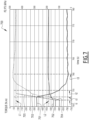
- a graph 700 is shown on figure 7 .
- the graph 700 shows the evolution of several parameters of the engine 12 during the initial phase 100 and dual phase 101.
- the horizontal axis is a time axis - expressed in seconds -.
- engine speed is considered constant.
- the graph 700 comprises a first curve 701, which shows the evolution of a torque - expressed in Newton ⁇ meter, or N-m - of the engine 12. On the left hand side vertical axis, the torque is negative, since the engine 12 is in the engine brake mode.
- the graph 700 comprises a second curve 702, which shows the evolution of the exhaust pressure P3, expressed in kPa relative to the right hand side vertical axis.
- the graph 700 comprises a second curve 702, which shows the evolution of the boost pressure P2, expressed in kPa relative to the right hand side vertical axis.
- the graph 700 comprises a third curve 703, which shows the evolution of the exhaust pressure P3, expressed in kPa relative to the right hand side vertical axis.
- the graph 700 comprises a fourth curve 704, which shows the evolution of a set-point of the boost pressure P2, expressed in kPa relative to the right hand side vertical axis.
- the graph 700 comprises a fifth curve 705, which shows the evolution of a set-point of the exhaust pressure P3, expressed in kPa relative to the right hand side vertical axis.
- the set-point of the exhaust pressure P3 is gradually set to the first threshold L1.
- the initial instant ti marks the beginning of the first phase 100A.
- the set-point of the boost pressure P2 is also gradually set to the second threshold L2.
- the torque 701 shows an initial plateau, around -330 N.m, prior to the initial instant t i .
- the exhaust pressure P3 is controlled by the restriction device 40.
- the exhaust pressure P3 starts to rise, in order to narrow the gap with the first threshold L1. Consequently, the torque 701 sharply decreases. In other words, the effect of the engine brake increase.
- the difference between the first instant t 1 and initial instant ti is about 0.1 s.
- the boost pressure P2 From the first instant t1, the boost pressure P2 also starts to rise, narrowing the gap with the second threshold L2. At a second instant t 2 , which is posterior to the first instant t1, the boost pressure P2 is sensibly equal to the second threshold L2, while the exhaust pressure P3 continues to rise, and the torque 701 continues to decrease.
- the exhaust pressure P3 reaches a maximal value, which is sensibly equal to the first threshold L1.
- the torque 701 continues to decrease.
- the third instant t3 marks the end of the first phase 100A and the beginning of the second phase 100B.
- the boost pressure P2 is already sensibly equal to the second threshold L2, so the second phase 100B ends immediately and the dual phase 101 starts from the third instant t3 on.
- a duration of the initial phase 100 is sensibly equal to the difference between the third instant t3 and the first instant t1, which is here around 0.7 s.
- the initial phase restarts, back to the first phase 100A.
- This situation might appear in abnormal situation, for example if one of the components of the engine 12 is dysfunctioning.
- the boost-pressure P2 reaches the second threshold L2 before the pre-determined time period, then the initial phase 100 ends and the dual phase 101 starts.
- the boost pressure regulation device 42 regulates the air exhaust pressure P3 in the exhaust manifold 22 in closed loop, in order to regulate the exhaust pressure P3 to the pre-determined first threshold L1, while the exhaust gas restriction device 40 controls the boost pressure P2 in closed loop, in order to regulate the boost pressure P2 to the pre-determined second threshold L2.
- the exhaust pressure P3, the boost pressure P2 and the torque 701 are relatively stable.
- the boost pressure regulation device 42 is the intake throttle valve.
- the intake throttle valve forms the boost pressure regulation device 42 and regulates the air exhaust pressure in the exhaust manifold 22 in closed loop.
- the turbocharger 30 is a variable geometry turbocharger VGT, which comprises moveable elements to adjust an output of the turbocharger 30, thus forming the boost pressure regulation device 42 when the engine 12 is in the motoring mode.
- the variable geometry turbocharger VGT forms the boost pressure regulation device 42 and regulates the air exhaust pressure P3 in the exhaust manifold 22 in closed loop.
- Relative terms such as “below” or “above” or “upper” or “lower” or “horizontal” or “vertical” may be used herein to describe a relationship of one element to another element as illustrated in the Figures. It will be understood that these terms and those discussed above are intended to encompass different orientations of the device in addition to the orientation depicted in the Figures. It will be understood that when an element is referred to as being “connected” or “coupled” to another element, it can be directly connected or coupled to the other element, or intervening elements may be present. In contrast, when an element is referred to as being “directly connected” or “directly coupled” to another element, there are no intervening elements present.
Landscapes
- Engineering & Computer Science (AREA)
- Mechanical Engineering (AREA)
- General Engineering & Computer Science (AREA)
- Chemical & Material Sciences (AREA)
- Combustion & Propulsion (AREA)
- Supercharger (AREA)
Abstract
Description
- The disclosure relates generally to engine brake for turbocharged engine vehicles. In particular aspects, the disclosure relates to an engine brake method for operating a vehicle with a turbocharged internal combustion engine and to a vehicle configured to implement such an engine brake method. The disclosure can be applied to heavy-duty vehicles, such as trucks, buses, and construction equipment, among other vehicle types. Although the disclosure may be described with respect to a particular vehicle, the disclosure is not restricted to any particular vehicle.
- Engine brake is a critical feature for commercial vehicles as it makes it possible to maintain a constant speed downhill for long periods without using the foundation brakes, which is favorable to both safety and drivability. Engine brake is typically achieved by using both a compression release system, for example a so-called Jacobs bleeder brake, and an exhaust gas restriction device, for example a proportional flap, which is installed after the turbocharger's turbine and which controls a target air pressure in the exhaust manifold. Unfortunately, this control strategy achieves limited results in terms of braking power, since closing the flap also results in decreasing the airflow going through the engine. This has several secondary negative effects, such as overheating nozzle tips of the fuel injectors - by lack of air to cool them down -, increasing oil rejection at the outlet of the turbocharger's compressor - by lack of air pressure in the compressor housing to keep its seal tight -, etc.
- Alternative approaches have tried to solve these issues. For example, on engines comprising a turbocharger with moveable elements to adjust an output of the turbocharger - also called VGT -, an alternative to using the exhaust flap is to control the exhaust back-pressure with the VGT instead: this is known as "VGT braking". Increasing the exhaust back-pressure with the VGT also increases the air flow at the same time, which benefits to the efficiency of the compression release system. However, since it also results in a reduced difference between intake pressure and exhaust pressure, braking power is actually not much improved with VGT braking. Another drawback of this strategy lies in its slow and sluggish response, up to several seconds, caused by the time it takes to pressurize the whole intake system.
- The invention aims at solving the problems mentioned above, by providing an engine brake method achieving a high braking power output while keeping operating parameters - such as injector cooling - within their specified ranges.
- According to a first aspect of the disclosure, the invention concerns an engine brake method for operating a vehicle with a turbocharged internal combustion engine. The engine comprises:
- several cylinders, which are connected to an intake manifold, collecting fresh air, and to an exhaust manifold, collecting exhaust air from the cylinders,
- a turbocharger; with a compressor driven by a turbine, the compressor being configured to increase a boost pressure of the fresh air in the intake manifold, while the turbine is configured to be driven by the exhaust air flowing from the exhaust manifold;
- a boost pressure regulation device, which is configured to adjust the boost pressure in the intake manifold, and
- an exhaust gas restriction device, which is located downstream from the turbine and which is configured to adjust an exhaust air pressure in the exhaust manifold.
- The engine brake method comprises a dual phase during which, simultaneously:
- the boost pressure regulation device regulates the air exhaust pressure in the exhaust manifold in closed loop, in order to regulate the exhaust pressure to a pre-determined first threshold, and
- the exhaust gas restriction device controls the boost pressure in closed loop, in order to regulate the boost pressure to a pre-determined second threshold.
- A technical benefit may include increasing both boost pressure and air exhaust pressure, thus resulting in a higher engine brake effect. Simultaneously, the air flow through the cylinders remains at a higher level, contributing to the cooling of the injector tips. Additionally, the pressure differential between boost pressure and air exhaust pressure remains positive, preventing oil leaks through the compressor seal. On steep downhill roads, it is therefore possible to increase the load of the vehicle, and/or to drive the vehicle on steeper roads, while regulating the speed of the vehicle solely based on engine brake, i.e. without using the foundation brake. The overall safety of the vehicle is therefore improved.
- Optionally in some examples, including in at least one preferred example, the engine comprises an intake throttle valve, which is arranged between the turbocharger and the intake manifold and which is configured to control the boost pressure, whereas during the dual phase, the intake throttle valve forms the boost pressure regulation device and regulates the air exhaust pressure in the exhaust manifold in closed loop. A technical benefit may include implementing the dual phase by using commonly used equipment.
- Optionally in some examples, including in at least one preferred example, the turbocharger is a variable geometry turbocharger, which comprises moveable elements to adjust an output of the turbocharger, whereas during the dual phase, the variable geometry turbocharger forms the boost pressure regulation device and regulates the air exhaust pressure in the exhaust manifold in closed loop. A technical benefit may include implementing the dual phase by using commonly used equipment.
- Optionally in some examples, including in at least one preferred example, the engine brake method further comprising an initial phase, prior to the dual phase. The initial phase comprises a first phase, during which the exhaust air pressure is controlled by the restriction device while the turbocharger is in open loop, so as to let exhaust air pressure to increase up to the first threshold, and a second phase, which follows the first phase and during which, once the exhaust air pressure reaches the first threshold, the restriction device is locked in position, while the turbocharger controls the air exhaust pressure in the exhaust manifold in closed loop, so as to let boost pressure increase up to the second threshold. If, during the second phase, the boost-pressure reaches the second threshold before a pre-determined time period, then the initial phase ends and the dual phase starts. A technical benefit may include ensuring a smooth, stable and rapid transition from the motoring mode of the engine to the engine brake mode.
- Optionally in some examples, including in at least one preferred example, the engine further comprises bleeder valves, each bleeder valve being associated with a respective cylinder and being configured to, when activated, let compressed air to leak from the cylinders through an opening of the bleeder valve, whereas the engine brake method comprises adjusting an opening of the bleeder valve, in order to maximize a braking effect of the engine during the dual phase. A technical benefit may include improving further the engine brake performance of the vehicle.
- Optionally in some examples, including in at least one preferred example, the dual phase is engaged when the engine has a speed, given in revolutions per minute, above a pre-determined third threshold. A technical benefit may include ensuring a higher engine brake effect compared to prior art methods.
- According to a second aspect of the disclosure, the invention concerns a vehicle, comprising a turbocharged internal combustion engine. The vehicle is configured to implement the engine brake method according to any one of preceding claims. The engine comprises:
- several cylinders, which are connected to an intake manifold, which is configured to collect fresh air, and to an exhaust manifold, which is configured to collect exhaust air from the cylinders,
- a turbocharger; with a compressor driven by a turbine, the compressor being configured to increase a boost pressure in the intake manifold, while the turbine is configured to be driven by the exhaust air flowing from the exhaust manifold;
- a boost pressure regulation device, which is configured to adjust the boost pressure in the intake manifold, and
- an exhaust gas restriction device, which is located downstream from the turbine and which is configured to increase an exhaust air pressure in the exhaust manifold.
- The second aspect of the disclosure may seek to provide a vehicle, for example a truck, with an improved engine brake capacity. A technical benefit may include allowing a higher load on downhill roads and/or allowing speed regulation on steeper downhill roads.
- The disclosed aspects, examples, and/or accompanying claims may be suitably combined with each other as would be apparent to anyone of ordinary skill in the art. Additional features and advantages are disclosed in the following description, claims, and drawings, and in part will be readily apparent therefrom to those skilled in the art or recognized by practicing the disclosure as described herein.
-
-
FIG. 1 represents, on two inserts a) and b); an exemplary vehicle according to the invention and an engine of this vehicle. -
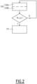
FIG. 2 is an exemplary synoptic diagram representing an engine brake method implemented with the vehicle offigure 1 . -
FIG. 3 to 6 are exemplary graphs comparing results obtained with the engine brake method according to the invention and according to prior art methods. -
FIG. 7 is an exemplary graph illustrating an initial phase of the engine brake method according to the invention. - The detailed description set forth below provides information and examples of the disclosed technology with sufficient detail to enable those skilled in the art to practice the disclosure.
- A
vehicle 10 is represented onfigure 1a ). Thevehicle 10 is a road vehicle, in particular a truck, which compriseswheels 11. Thevehicle 10 comprises anengine 12, which is schematically shown onfigure 1b ). Theengine 12 is an internal combustion engine, which is configured to use fuel in order to drive thewheels 11 in rotation, in order to move thevehicle 10. When theengine 12 uses fuel to rotate thewheel 10, theengine 12 is in a motoring mode. On the contrary, when theengine 12 is used to waste energy, theengine 12 is in an "engine brake" mode, that is to say theengine 12 applies a braking torque to thewheels 11. Onfigure 1 , thevehicle 10 is represented on a downhill slope S, where thevehicle 10 tends to naturally accelerate because of gravity. Theengine 12 is used in the engine brake mode in order to regulate a speed of thevehicle 10. - The
engine 12 comprises amain block 14 withseveral cylinders 16. In the illustrated example, theengine 12 is a four-stroke engine with sixcylinders 16. For eachcylinder 16, the four strokes include, successively, an intake stroke, a compression stroke, an expansion stroke, and an exhaust stroke. - When the
engine 12 is running, during the intake stroke or eachcylinder 16, fresh air flowing through anintake manifold 20 is admitted into eachcylinder 16, through at least one intake valve. The at least one intake valve is not represented. During the exhaust stroke, air contained in thecylinder 16 is evacuated through at least one exhaust valve and collected in anexhaust manifold 22. The at least one exhaust valve is not represented. In other words, thecylinders 16 are connected to theintake manifold 20, which collects fresh air, and to theexhaust manifold 22, which collects exhaust air from thecylinders 16. When theengine 12 is in the motoring mode, fuel is injected in the cylinders and the air + fuel mix is ignited during the compression and expansion strokes. During the following exhaust stroke, the air evacuated from thecylinders 16 is hot and contains various substances and residues resulting from fuel combustion. Air containing these combustion residues is also called exhaust gas. - When the
engine 12 is in the engine brake mode, no fuel is injected into thecylinders 16 and no combustion occurs. The air evacuated from thecylinders 16 during the exhaust stroke is mostly fresh air that has been admitted during the intake stroke, then compressed and expanded inside thecylinders 16 during the compression and expansion strokes. - Air flowing from the
cylinders 16 into theexhaust manifold 22 is also called "exhaust air". Fresh air flowing from theintake manifold 20 into thecylinders 16 is also called "charge air". Theintake manifold 20 is located upstream from thecylinders 16 relative to the normal flow of air in theengine 12, while theexhaust manifold 22 is located downstream from thecylinders 16 relative to the normal flow of air in theengine 12. In the following description, the notions of "upstream" and "downstream" are considered relatively to the flow of air during normal use of theengine 12. "Normal use" means that theengine 12 is either in the motoring mode, either in the engine brake mode. - The
engine 12 also comprises aturbocharger 30. Theturbocharger 30 comprises a compressor 32 and aturbine 34, the compressor 32 being linked to theturbine 34 by anaxle 36. Theturbine 34 is configured to be driven in rotation by the exhaust air flowing from theexhaust manifold 22, while the compressor 32 is configured to increase a pressure of the charge air flowing in theintake manifold 20 then into thecylinders 16. - When the
engine 12 is in the engine brake mode, during the compression / expansion strokes in eachcylinder 16, air pressure reaches a peak, called "peak cylinder pressure" PCP. In the schematic example offigure 1b ), one of thecylinder 16 comprises a first pressure sensor, here represented figuratively by a manometer, the first pressure sensor being configured to measure air pressure within thecylinder 16. In particular, the first pressure sensor, also referenced PCP, is configured to measure the peak cylinder pressure. Of course, in reality there is no manometer inside any one of thecylinders 16. - A second pressure sensor P2, represented figuratively by a manometer, is arranged on the
intake manifold 20, the second pressure sensor P2 being configured to measure a boost pressure, that is to say an air pressure inside theintake manifold 20. By extension, boost pressure is also referenced P2. A third pressure sensor P3, represented figuratively by a manometer, is arranged on theexhaust manifold 22, the third pressure sensor P3 being configured to measure an exhaust pressure, that is to say an air pressure inside theexhaust manifold 22. By extension, exhaust pressure is also referenced P3. - The engine also comprises an exhaust
gas restriction device 40, which is located downstream from theturbine 34 and which is configured to regulate the exhaust pressure P3 in theexhaust manifold 22. In the illustrated example, the exhaustgas restriction device 40 is a flap, also called "exhaust flap". The shape and type of the exhaustgas restriction device 40 are not limitative. - The
engine 10 also comprises a fourth pressure sensor P4A, represented figuratively by a manometer, which is arranged downstream from theturbine 34 and which is configured to measure a turbine outlet pressure, that is to say a pressure of exhaust air at an outlet of theturbine 34, between theturbine 34 and the exhaustgas restriction device 40. By extension, the turbine outlet pressure is also referenced P4A. - The
engine 10 also comprises a boostpressure regulation device 42, which is configured to adjust the boost pressure P2 in theintake manifold 20. In the illustrated example, the boostpressure regulation device 42 is an intake throttle valve, which is represented by a flap and which is arranged between theturbocharger 30 and theintake manifold 20, and which is configured to control the boost pressure P2. The shape and type of the boostpressure regulation device 42 are not limitative. - Schematically, braking torque from the
engine 12 comes mainly from the combination of two phenomena. A first phenomenon is called pumping torque, which is caused by the exhaust pressure P3 being higher than the boost pressure P2. The higher the difference between P3 and P2, the higher the braking torque. A second phenomenon is called compression release torque, or compression brake. Eachcylinder 16 is advantageously equipped with ableeder valve 17, which is configured to let the air compressed inside thecylinder 16 to leak from thecylinder 16 through an opening of thebleeder valve 17 when theengine 12 is in the engine brake mode, while eachbleeder valve 17 remains closed when theengine 12 is in the motoring mode. - Without a bleeder valve, when air is compressed in the
cylinders 16 during the compression stroke, the mechanical energy invested in compressing air is almost entirely recovered by the expansion within thecylinder 16 during the expansion stroke. Thanks to thebleeder valve 17, the compressed air is released outside thecylinder 16 through the opening of thebleeder valve 17, and the energy that went into making the compression is wasted by releasing the compressed air instead of letting it expand inside thecylinder 16. The higher the peak cylinder pressure PCP, prior to releasing this compressed air, the higher the wasted energy, and the higher the braking torque generated by compression brake. - According to some examples, the
bleeder valve 17 is a specific device, different from the intake and exhaust valves. Alternatively, thebleeder valve 17 comprises an actuator that is configured to slightly open one or more existing exhaust valve(s) when theengine 12 is in the engine brake mode. Such type of bleeder valve is also known as "Jacobs valve", and compression brake using such a Jacobs valve is also called "Jacobs brake". - In short, when the
engine 12 is in the engine brake mode, maximizing braking torque involves maximizing both the peak cylinder pressure PCP and the pressure difference between exhaust pressure and intake pressure, P3-P2. To achieve this, theengine 12 is configured to implement an engine brake method, the engine brake method comprising a phase, called "dual phase" 101, during which, simultaneously: - the boost
pressure regulation device 42 regulates the air exhaust pressure P3 in theexhaust manifold 22 in closed loop, in order to regulate the exhaust pressure to a pre-determined first threshold, and - the exhaust
gas restriction device 40 controls the boost pressure P2 in closed loop, in order to regulate the boost pressure P2 to a pre-determined second threshold. - Advantageously, the engine brake method comprises adjusting the opening of the
bleeder valve 17 to a specific predetermined target value, in order to maximize a braking torque of theengine 12 during the dual phase. The target value of the opening of the bleeder valve depends on the type, size, power, etc., of theengine 12. - Using the boost
pressure regulation device 42 to control the exhaust pressure P3 in closed loop makes theturbocharger 30 draw a lot of fresh air into theengine 12, which increases peak cylinder pressure PCP and cools down the injector tips. Using the exhaustgas restriction device 40 to control P2 in closed loop decreases an expansion ratio of theturbine 34, thus limiting boost pressure P2 to values significantly lower than P3 and contributing to a higher pumping torque. The pressure differential P3-P2 remains positive, which keeps the compressor 32's seal tight. - Results and benefits of the dual phase are illustrated on
figures 3 to 6 . - A
graph 300 is shown onfigure 3 . Thegraph 300 shows the evolution, for anexemplary vehicle 10, of the exhaust pressure P3 - expressed in kilo Pascal, or kPa - vs. a speed of the engine 12 - expressed in revolutions per minute, or RPM -. - The
graph 300 comprises afirst curve 301, which illustrates the exhaust pressure P3 when theengine 12 is controlled according to a prior art method. Within the scope of the present description, engine brake according to the prior art method means that the exhaust air pressure P3 is controlled by therestriction device 40 while theturbocharger 30 is in open loop. Thegraph 300 comprises asecond curve 302, which illustrated the exhaust pressure P3 when theengine 12 is controlled with thedual phase 101 method according to the invention. - As seen on the
graph 300, thesecond curve 302 is significantly above thefirst curve 301 when the engine speed is higher than a pre-determined threshold T300, which is equal to 1800 RPM in the illustrated example. In other words, thanks to the invention, the exhaust pressure P3 is higher when the engine speed is above the threshold T300. - A
graph 400 is shown onfigure 4 . Thegraph 400 shows the evolution, for anexemplary vehicle 10, of the boost pressure P2 - expressed in kPa - vs. the speed of the engine 12 - expressed in RPM -. - The
graph 400 comprises afirst curve 401, which illustrates the boost pressure P2 when theengine 12 is controlled according to the prior art method. Thegraph 400 comprises asecond curve 402, which illustrated the boost pressure P2 when theengine 12 is controlled with thedual phase 101 method according to the invention. - As seen on the
graph 400, for all illustrated engine speed, thesecond curve 402 is significantly above thefirst curve 401. In other words, thanks to the invention, the boost pressure P2 is higher when theengine 12 is controlled with the method according to the invention compared to when theengine 12 is controlled with the prior art method. In particular, in the illustrated example, when the engine speed is above a threshold T400, which is here equal to 1400 RPM, the boost pressure P2 when theengine 12 is controlled with the method according to the invention is at least ten times higher than the boost pressure P2 when theengine 12 is controlled with the prior art method. - A
graph 500 is shown onfigure 5 . Thegraph 500 shows the evolution, for anexemplary vehicle 10, of the engine brake power - expressed in kilo Watt, or kW - vs. the speed of the engine 12 - expressed in RPM -. - The
graph 500 comprises afirst curve 501, which illustrates the engine brake power when theengine 12 is controlled according to the prior art method. Thegraph 500 comprises asecond curve 502, which illustrated the engine brake power when theengine 12 is controlled with thedual phase 101 method according to the invention. - As seen on the
graph 500, thesecond curve 502 is significantly above thefirst curve 501 when the engine speed is higher than a pre-determined threshold T500, which is equal to 1400 RPM in the illustrated example. In other words, thanks to the invention, the boost pressure P2 is higher when theengine 12 is controlled with the method according to the invention compared to when theengine 12 is controlled with the prior art method. - In other words, in order to benefit from a higher braking power, the
dual phase 101 is engaged when the engine speed is above a pre-determined threshold. In the illustrated example, this threshold is equal to 1400 RPM. - Thanks to control method according to the invention, it is possible to control simultaneously both boost pressure P2 and exhaust pressure P3, which results in an engine brake power significantly higher than what was achievable with the prior art method.
- A
graph 600 is shown onfigure 6 . Thegraph 600 shows the evolution, for anexemplary vehicle 10, of a temperature of the tip of an injector's nozzle - nozzle tip temperature, or NTT, expressed in degrees Celsius, or °C - vs. the speed of the engine 12 - expressed in RPM -. - The
graph 600 comprises afirst curve 601, which illustrates the nozzle tip temperature NTT when theengine 12 is controlled with the prior art method. Thegraph 600 comprises asecond curve 602, which illustrated the nozzle tip temperature NTT when theengine 12 is controlled with thedual phase 101 method according to the invention. - As seen on the
graph 600, for all illustrated engine speed, thesecond curve 602 is below thefirst curve 601. In other words, thanks to the invention, the nozzle tip temperature NTT is lower when theengine 12 is controlled with the method according to the invention compared to when theengine 12 is controlled with prior art methods. This is caused by the higher air flow flowing through thecylinders 16, since - among others - the boost pressure P2 is higher in the dual mode compared to prior art methods, as illustrated ongraph 400. - When the
vehicle 10 is running, moving between flat or uphill roads to downhill roads, theengine 12 must transition between motoring mode and engine brake mode. Thedual phase 101 method correspond to an established state of theengine 12 in the engine brake method. Prior to thedual phase 101, the engine brake method according to the invention also comprises aninitial phase 100, which is implemented to ensure the transition between the motoring mode and thedual phase 101 of the engine brake mode. - The
initial phase 100 is divided in two sub-phase, which include andfirst phase 100A and asecond phase 100B, which follows thefirst phase 100A. - As the
engine 12 is initially in the motoring mode, and theengine 12 is controlled to switch to the engine brake mode. The engine speed, which is linked to the rotation speed of thewheels 11, is supposed to remain sensibly constant during the initial phase. During thefirst phase 100A, the exhaust air pressure P3 is controlled by therestriction device 40 while theturbocharger 30 is in open loop, so as to let exhaust air pressure P3 to increase up to a pre-determined first threshold L1. - Once the exhaust air pressure P3 reaches the first threshold L1, the
second phase 100B starts. During thesecond phase 100B, therestriction device 40 is locked in position - in other words therestriction device 40 does not regulate exhaust air pressure P3 -, while theturbocharger 30 controls the air exhaust pressure P3 in theexhaust manifold 22 in closed loop, so as to let boost pressure P2 increase up to a pre-determined second threshold L2. - During the
second phase 100B, if the boost-pressure P2 reaches the second threshold before a pre-determined time period, then the initial phase ends and thedual phase 101 starts. If the boost-pressure P2 does not reach the second threshold, then thedual phase 101 does not start, and the engine reverts to thefirst phase 100A. - A
graph 700 is shown onfigure 7 . Thegraph 700 shows the evolution of several parameters of theengine 12 during theinitial phase 100 anddual phase 101. The horizontal axis is a time axis - expressed in seconds -. In the example offigure 7 , engine speed is considered constant. - The
graph 700 comprises afirst curve 701, which shows the evolution of a torque - expressed in Newton × meter, or N-m - of theengine 12. On the left hand side vertical axis, the torque is negative, since theengine 12 is in the engine brake mode. - The
graph 700 comprises asecond curve 702, which shows the evolution of the exhaust pressure P3, expressed in kPa relative to the right hand side vertical axis. Thegraph 700 comprises asecond curve 702, which shows the evolution of the boost pressure P2, expressed in kPa relative to the right hand side vertical axis. Thegraph 700 comprises athird curve 703, which shows the evolution of the exhaust pressure P3, expressed in kPa relative to the right hand side vertical axis. Thegraph 700 comprises afourth curve 704, which shows the evolution of a set-point of the boost pressure P2, expressed in kPa relative to the right hand side vertical axis. Thegraph 700 comprises afifth curve 705, which shows the evolution of a set-point of the exhaust pressure P3, expressed in kPa relative to the right hand side vertical axis. - In the illustrated example, at an initial instant ti, the set-point of the exhaust pressure P3 is gradually set to the first threshold L1. The initial instant ti marks the beginning of the
first phase 100A. In the illustrated example, starting at the initial instant ti, the set-point of the boost pressure P2 is also gradually set to the second threshold L2. Thetorque 701 shows an initial plateau, around -330 N.m, prior to the initial instant ti. The exhaust pressure P3 is controlled by therestriction device 40. - At a first instant t1, which is posterior to the initial instant ti, the exhaust pressure P3 starts to rise, in order to narrow the gap with the first threshold L1. Consequently, the
torque 701 sharply decreases. In other words, the effect of the engine brake increase. In the illustrated example, the difference between the first instant t1 and initial instant ti is about 0.1 s. - From the first instant t1, the boost pressure P2 also starts to rise, narrowing the gap with the second threshold L2. At a second instant t2 , which is posterior to the first instant t1, the boost pressure P2 is sensibly equal to the second threshold L2, while the exhaust pressure P3 continues to rise, and the
torque 701 continues to decrease. - At a third instant t3, which is posterior to the second instant t2, the exhaust pressure P3 reaches a maximal value, which is sensibly equal to the first threshold L1. Between the second instant t2 and third instant t3, the
torque 701 continues to decrease. - The third instant t3 marks the end of the
first phase 100A and the beginning of thesecond phase 100B. In the illustrated example, the boost pressure P2 is already sensibly equal to the second threshold L2, so thesecond phase 100B ends immediately and thedual phase 101 starts from the third instant t3 on. In the illustrated example, a duration of theinitial phase 100 is sensibly equal to the difference between the third instant t3 and the first instant t1, which is here around 0.7 s. - More generally, if, during the
second phase 100B, the boost-pressure P2 does not reach the second threshold L2 before a pre-determined time period, then the initial phase restarts, back to thefirst phase 100A. This situation might appear in abnormal situation, for example if one of the components of theengine 12 is dysfunctioning. In a normal situation, if during thesecond phase 100B, the boost-pressure P2 reaches the second threshold L2 before the pre-determined time period, then theinitial phase 100 ends and thedual phase 101 starts. - During the
dual phase 101, the boostpressure regulation device 42 regulates the air exhaust pressure P3 in theexhaust manifold 22 in closed loop, in order to regulate the exhaust pressure P3 to the pre-determined first threshold L1, while the exhaustgas restriction device 40 controls the boost pressure P2 in closed loop, in order to regulate the boost pressure P2 to the pre-determined second threshold L2. As shown onfigure 7 , during thedual phase 101, the exhaust pressure P3, the boost pressure P2 and thetorque 701 are relatively stable. - In the illustrated example, the boost
pressure regulation device 42 is the intake throttle valve. During thedual phase 101, the intake throttle valve forms the boostpressure regulation device 42 and regulates the air exhaust pressure in theexhaust manifold 22 in closed loop. - In a non illustrated alternative embodiment, the
turbocharger 30 is a variable geometry turbocharger VGT, which comprises moveable elements to adjust an output of theturbocharger 30, thus forming the boostpressure regulation device 42 when theengine 12 is in the motoring mode. During thedual phase 101 of the engine brake method, the variable geometry turbocharger VGT forms the boostpressure regulation device 42 and regulates the air exhaust pressure P3 in theexhaust manifold 22 in closed loop. - The terminology used herein is for the purpose of describing particular aspects only and is not intended to be limiting of the disclosure. As used herein, the singular forms "a," "an," and "the" are intended to include the plural forms as well, unless the context clearly indicates otherwise. As used herein, the term "and/or" includes any and all combinations of one or more of the associated listed items. It will be further understood that the terms "comprises", "comprising", "includes", and/or "including" when used herein specify the presence of stated features, integers, actions, steps, operations, elements, and/or components, but do not preclude the presence or addition of one or more other features, integers, actions, steps, operations, elements, components, and/or groups thereof.
- It will be understood that, although the terms first, second, etc., may be used herein to describe various elements, these elements should not be limited by these terms. These terms are only used to distinguish one element from another. For example, a first element could be termed a second element, and, similarly, a second element could be termed a first element without departing from the scope of the present disclosure.
- Relative terms such as "below" or "above" or "upper" or "lower" or "horizontal" or "vertical" may be used herein to describe a relationship of one element to another element as illustrated in the Figures. It will be understood that these terms and those discussed above are intended to encompass different orientations of the device in addition to the orientation depicted in the Figures. It will be understood that when an element is referred to as being "connected" or "coupled" to another element, it can be directly connected or coupled to the other element, or intervening elements may be present. In contrast, when an element is referred to as being "directly connected" or "directly coupled" to another element, there are no intervening elements present.
- Unless otherwise defined, all terms used herein have the same meaning as commonly understood by one of ordinary skill in the art to which this disclosure belongs. It will be further understood that terms used herein should be interpreted as having a meaning consistent with their meaning in the context of this specification and the relevant art and will not be interpreted in an idealized or overly formal sense unless expressly so defined herein.
- It is to be understood that the present disclosure is not limited to the aspects described above and illustrated in the drawings; rather, the skilled person will recognize that many changes and modifications may be made within the scope of the present disclosure and appended claims. In the drawings and specification, there have been disclosed aspects for purposes of illustration only and not for purposes of limitation, the scope of the disclosure being set forth in the following claims.
Claims (7)
- An engine brake method for operating a vehicle (10) with a turbocharged internal combustion engine (12), wherein:- the engine (12) comprises:• several cylinders (16), which are connected to an intake manifold (20), collecting fresh air, and to an exhaust manifold (22), collecting exhaust air from the cylinders (16),• a turbocharger (30); with a compressor (32) driven by a turbine (34), the compressor (32) being configured to increase a boost pressure (P2) of the fresh air in the intake manifold (20), while the turbine (34) is configured to be driven by the exhaust air flowing from the exhaust manifold (22);• a boost pressure regulation device (42), which is configured to adjust the boost pressure (P2) in the intake manifold (20),• an exhaust gas restriction device (40), which is located downstream from the turbine (34) and which is configured to regulate an air exhaust pressure (P3) in the exhaust manifold (22),- the engine brake method comprises a dual phase (101) during which, simultaneously:• the boost pressure regulation device (42) regulates the air exhaust pressure (P3) in the exhaust manifold (22) in closed loop, in order to regulate the exhaust pressure to a pre-determined first threshold (L1),• the exhaust gas restriction device (40) controls the boost pressure (P2) in closed loop, in order to regulate the boost pressure (P2) to a pre-determined second threshold (L2).
- The engine brake method according to claim 1, wherein:- the engine (12) comprises an intake throttle valve, which is arranged between the turbocharger (30) and the intake manifold (20) and which is configured to control the boost pressure (P2),- during the dual phase (101), the intake throttle valve forms the boost pressure regulation device (42) and regulates the air exhaust pressure (P3) in the exhaust manifold (22) in closed loop.
- The engine brake method according to claim 1, wherein:- the turbocharger (30) is a variable geometry turbocharger (VGT), which comprises moveable elements to adjust an output of the turbocharger,- during the dual phase (101), the variable geometry turbocharger forms the boost pressure regulation device (42) and regulates the air exhaust pressure (P3) in the exhaust manifold (22) in closed loop.
- The engine brake method according to any one of claims 1 to 3, further comprising an initial phase (100), prior to the dual phase (101), wherein:- the initial phase comprises:• a first phase (100A), during which the air exhaust pressure (P3) is controlled by the restriction device (40) while the turbocharger (30) is in open loop, so as to let exhaust air pressure (P3) to increase up to the first threshold (L1),• a second phase (100B), which follows the first phase (100A) and during which, once the exhaust air pressure (P3) reaches the first threshold (L1), the restriction device (40) is locked in position, while the turbocharger (30) controls the air exhaust pressure (P3) in the exhaust manifold (22) in closed loop, so as to let boost pressure (P2) increase up to the second threshold (L2),- if, during the second phase (101B), the boost-pressure reaches the second threshold (L2) before a pre-determined time period, then the initial phase (100) ends and the dual phase (101) starts.
- The engine brake method according to any one of claims 1 to 4, wherein:- the engine (12) further comprises bleeder valves (17), each bleeder valve being associated with a respective cylinder (16) and being configured to, when activated, let compressed air to leak from the cylinders (16) through an opening of the bleeder valve,- the engine brake method comprises adjusting an opening of the bleeder valve, in order to maximize a braking effect of the engine (12) during the dual phase (101).
- The engine brake method according to any one of claims 1 to 5, wherein:- the dual phase (101) is engaged when the engine (12) has a speed, given in revolutions per minute, above a pre-determined third threshold.
- A vehicle (10), comprising a turbocharged internal combustion engine (12), wherein:- the vehicle (10) is configured to implement the engine brake method according to any one of claims 1 to 6,- the engine (12) comprises:• several cylinders (16), which are connected to an intake manifold (20), which is configured to collect fresh air, and to an exhaust manifold (22), which is configured to collect exhaust air from the cylinders (16),• a turbocharger (30), with a compressor (32) driven by a turbine (34), the compressor (32) being configured to increase a boost pressure (P2) in the intake manifold (20), while the turbine (34) is configured to be driven by the exhaust air flowing from the exhaust manifold (22);• a boost pressure (P2) regulation device (42), which is configured to adjust the boost pressure (P2) in the intake manifold (20),• an exhaust gas restriction device (40), which is located downstream from the turbine (34) and which is configured to adjust an exhaust air pressure (P3) in the exhaust manifold (22).
Priority Applications (3)
| Application Number | Priority Date | Filing Date | Title |
|---|---|---|---|
| EP23191108.2A EP4506551A1 (en) | 2023-08-11 | 2023-08-11 | Engine brake method for operating a vehicle with a turbocharged internal combustion engine and associated vehicle |
| US18/794,102 US12392298B2 (en) | 2023-08-11 | 2024-08-05 | Engine brake method for operating a vehicle with a turbocharged internal combustion engine and associated vehicle |
| CN202411085223.2A CN119467103A (en) | 2023-08-11 | 2024-08-08 | Engine braking method for operating a vehicle having a turbocharged internal combustion engine and related vehicle |
Applications Claiming Priority (1)
| Application Number | Priority Date | Filing Date | Title |
|---|---|---|---|
| EP23191108.2A EP4506551A1 (en) | 2023-08-11 | 2023-08-11 | Engine brake method for operating a vehicle with a turbocharged internal combustion engine and associated vehicle |
Publications (1)
| Publication Number | Publication Date |
|---|---|
| EP4506551A1 true EP4506551A1 (en) | 2025-02-12 |
Family
ID=87570775
Family Applications (1)
| Application Number | Title | Priority Date | Filing Date |
|---|---|---|---|
| EP23191108.2A Pending EP4506551A1 (en) | 2023-08-11 | 2023-08-11 | Engine brake method for operating a vehicle with a turbocharged internal combustion engine and associated vehicle |
Country Status (3)
| Country | Link |
|---|---|
| US (1) | US12392298B2 (en) |
| EP (1) | EP4506551A1 (en) |
| CN (1) | CN119467103A (en) |
Citations (3)
| Publication number | Priority date | Publication date | Assignee | Title |
|---|---|---|---|---|
| US20020174849A1 (en) * | 2001-05-22 | 2002-11-28 | Brian Ruggiero | Method and system for engine braking in an internal combustion engine using a stroke limited high pressure engine brake |
| US20150047601A1 (en) * | 2012-04-25 | 2015-02-19 | Volvo Lastvagnar Ab | Method and engine brake system to control an engine brake of a vehicle |
| US20150144097A1 (en) * | 2012-06-07 | 2015-05-28 | Daf Trucks N.V. | Controlling a compression release brake |
Family Cites Families (6)
| Publication number | Priority date | Publication date | Assignee | Title |
|---|---|---|---|---|
| GB0615143D0 (en) | 2006-07-29 | 2006-09-06 | Cummins Turbo Tech Ltd | Multi-stage turbocharger system |
| US8640672B2 (en) | 2006-12-20 | 2014-02-04 | Volvo Lastvagnar Ab | Engine brake for vehicle |
| US8689770B2 (en) | 2009-11-02 | 2014-04-08 | International Engine Intellectual Property Company, Llc | High-temperature-flow engine brake with valve actuation |
| GB2493748A (en) * | 2011-08-17 | 2013-02-20 | Gm Global Tech Operations Inc | Unit for estimating the rotational speed of a turbocharger |
| AT516542B1 (en) | 2014-12-15 | 2019-12-15 | Man Truck & Bus Oesterreich Ag | Method for controlling an engine brake device and engine brake device |
| AT516513B1 (en) | 2014-12-15 | 2016-06-15 | MAN Truck & Bus Österreich AG | An engine braking device for an internal combustion engine and method for operating an engine braking device |
-
2023
- 2023-08-11 EP EP23191108.2A patent/EP4506551A1/en active Pending
-
2024
- 2024-08-05 US US18/794,102 patent/US12392298B2/en active Active
- 2024-08-08 CN CN202411085223.2A patent/CN119467103A/en active Pending
Patent Citations (3)
| Publication number | Priority date | Publication date | Assignee | Title |
|---|---|---|---|---|
| US20020174849A1 (en) * | 2001-05-22 | 2002-11-28 | Brian Ruggiero | Method and system for engine braking in an internal combustion engine using a stroke limited high pressure engine brake |
| US20150047601A1 (en) * | 2012-04-25 | 2015-02-19 | Volvo Lastvagnar Ab | Method and engine brake system to control an engine brake of a vehicle |
| US20150144097A1 (en) * | 2012-06-07 | 2015-05-28 | Daf Trucks N.V. | Controlling a compression release brake |
Also Published As
| Publication number | Publication date |
|---|---|
| CN119467103A (en) | 2025-02-18 |
| US12392298B2 (en) | 2025-08-19 |
| US20250052188A1 (en) | 2025-02-13 |
Similar Documents
| Publication | Publication Date | Title |
|---|---|---|
| CN103119270B (en) | Method for operating an internal combustion engine with a variable valve train | |
| US8931273B2 (en) | Stored compressed air management for improved engine performance | |
| JP3789149B2 (en) | Turbo compound combustion engine | |
| US9840972B2 (en) | Supercharger-based twin charging system for an engine | |
| US20130213350A1 (en) | Internal combustion engine exhaust brake control method and device | |
| JP5370243B2 (en) | Control device for diesel engine with turbocharger | |
| US20180274436A1 (en) | Methods and systems for an engine start using an electrically drivable compressor | |
| CN105697096A (en) | Method for controlling an engine braking device and engine braking device | |
| Lee et al. | Simulation-based assessment of various dual-stage boosting systems in terms of performance and fuel economy improvements | |
| US10731609B2 (en) | Methods and systems for energy recovery via an EGR cooler | |
| JP2006183605A (en) | Multistage supercharging system for internal combustion engine and control method thereof | |
| CN108463624A (en) | The method for controlling motor vehicles turbo-compressor Thermal Motor | |
| CN1930386B (en) | Control device for internal combustion engine with electric supercharger | |
| JP6112397B2 (en) | Supercharger control device for internal combustion engine | |
| US12392298B2 (en) | Engine brake method for operating a vehicle with a turbocharged internal combustion engine and associated vehicle | |
| JP6201645B2 (en) | Vehicle gas pressure accumulation system and vehicle gas pressure accumulation method | |
| JP4953100B2 (en) | Turbocharged internal combustion engine | |
| GB2490943A (en) | Method for operating an internal combustion engine with electrically powered turbo compressor | |
| JP5834505B2 (en) | Supercharging assist method for internal combustion engine and internal combustion engine | |
| JP5397291B2 (en) | Start control device for turbocharged engine | |
| JP2010001822A (en) | Internal combustion engine with turbocharger | |
| JP6990551B2 (en) | Engine control unit | |
| CN107642410B (en) | Internal combustion engine with exhaust-gas turbocharging device | |
| BR102024016302A2 (en) | ENGINE BRAKE METHOD FOR OPERATING A VEHICLE WITH A TURBOCHARGED INTERNAL COMBUSTION ENGINE AND ASSOCIATED VEHICLE | |
| JP7826990B2 (en) | Exhaust control device for internal combustion engine |
Legal Events
| Date | Code | Title | Description |
|---|---|---|---|
| PUAI | Public reference made under article 153(3) epc to a published international application that has entered the european phase |
Free format text: ORIGINAL CODE: 0009012 |
|
| STAA | Information on the status of an ep patent application or granted ep patent |
Free format text: STATUS: THE APPLICATION HAS BEEN PUBLISHED |
|
| AK | Designated contracting states |
Kind code of ref document: A1 Designated state(s): AL AT BE BG CH CY CZ DE DK EE ES FI FR GB GR HR HU IE IS IT LI LT LU LV MC ME MK MT NL NO PL PT RO RS SE SI SK SM TR |
|
| STAA | Information on the status of an ep patent application or granted ep patent |
Free format text: STATUS: REQUEST FOR EXAMINATION WAS MADE |
|
| 17P | Request for examination filed |
Effective date: 20250218 |
|
| STAA | Information on the status of an ep patent application or granted ep patent |
Free format text: STATUS: EXAMINATION IS IN PROGRESS |
|
| 17Q | First examination report despatched |
Effective date: 20251118 |