EP4506545A1 - Plant for generating energy - Google Patents
Plant for generating energy Download PDFInfo
- Publication number
- EP4506545A1 EP4506545A1 EP23190655.3A EP23190655A EP4506545A1 EP 4506545 A1 EP4506545 A1 EP 4506545A1 EP 23190655 A EP23190655 A EP 23190655A EP 4506545 A1 EP4506545 A1 EP 4506545A1
- Authority
- EP
- European Patent Office
- Prior art keywords
- steam
- compressor
- turbomachine
- plant
- water
- Prior art date
- Legal status (The legal status is an assumption and is not a legal conclusion. Google has not performed a legal analysis and makes no representation as to the accuracy of the status listed.)
- Withdrawn
Links
Images
Classifications
-
- F—MECHANICAL ENGINEERING; LIGHTING; HEATING; WEAPONS; BLASTING
- F01—MACHINES OR ENGINES IN GENERAL; ENGINE PLANTS IN GENERAL; STEAM ENGINES
- F01K—STEAM ENGINE PLANTS; STEAM ACCUMULATORS; ENGINE PLANTS NOT OTHERWISE PROVIDED FOR; ENGINES USING SPECIAL WORKING FLUIDS OR CYCLES
- F01K25/00—Plants or engines characterised by use of special working fluids, not otherwise provided for; Plants operating in closed cycles and not otherwise provided for
- F01K25/005—Plants or engines characterised by use of special working fluids, not otherwise provided for; Plants operating in closed cycles and not otherwise provided for the working fluid being steam, created by combustion of hydrogen with oxygen
Definitions
- the invention relates to a plant for generating energy, comprising a combustion chamber in which hydrogen and oxygen react with one another to give steam, further comprising a turbomachine having an inflow region fluidically connected to the combustion chamber, and also having a flow region designed such that the thermal energy from the steam is converted to mechanical energy, and an outflow region fluidically connected to the flow region.
- the invention further relates to a method of operating a plant, wherein hydrogen and oxygen react with one another in a combustion chamber to give steam and the steam is fed to a turbomachine in which the thermal energy from the steam is converted to mechanical energy.
- the invention pursues the aim of offering a plant that converts hydrogen to electrical energy.
- a turbomachine is used, which is energized with the steam formed by the reaction of hydrogen with oxygen in a combustion chamber, and converts the thermal energy from the steam to mechanical energy.
- a plant for generating energy comprising a combustion chamber in which hydrogen and oxygen react with one another to give steam, further comprising a turbomachine having an inflow region fluidically connected to the combustion chamber, and also having a flow region designed such that the thermal energy from the steam is converted to mechanical energy, and an outflow region fluidically connected to the flow region, further comprising a compressor designed to compress the steam coming from the turbomachine, wherein the compressor has a compression inlet region fluidically connected to the outflow region, wherein the compressor has multiple compressor stages designed to compress the steam, wherein the compressor stage is provided with an injection device designed to inject water from a water conduit into or between the compressor stages, wherein the compressor has a compressor outflow region from which the steam compressed in the compressor stages flows, further comprising a recuperator designed such that the thermal energy in the steam flowing out of the turbomachine is transferred to the steam flowing out of the compressor, wherein the recuperator has an inlet region fluidically connected to the compressor outflow region, wherein the recuperator has an outlet region fluidically connected
- the object is also achieved by a method of operating a plant, wherein hydrogen and oxygen react with one another in a combustion chamber to give steam and the steam is fed to a turbomachine in which the thermal energy from the steam is converted to mechanical energy, wherein the steam flowing out of the turbomachine is fed to a compressor with multiple compressor stages, wherein the pressure of the steam is increased in the compressor stages in the compressor, wherein water is fed into one compressor stage or fed between two compressor stages, wherein the steam coming from the compressor is fed to a recuperator arranged in such a way that the thermal energy of the steam coming from the turbomachine is transferred to the steam coming from the compressor, wherein the steam heated downstream of the recuperator is fed to the combustion chamber and the turbomachine.
- the invention makes it possible to provide a plant that requires only one cycle with a working medium.
- the invention proceeds from the idea that the steam as working medium is formed on ignition, which is understood to mean the chemical reaction of the hydrogen with the oxygen. As a result, no great amounts of water are required, which have to be heated and evaporated.
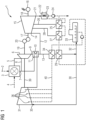
- the figure shows:
- Figure 1 shows a schematic diagram of one embodiment of an inventive plant 1.
- the plant 1 is designed for the generation of electrical energy and will now be elucidated in detail hereinafter.
- Hydrogen is fed to a combustion chamber 3 via a hydrogen conduit 2.
- the hydrogen may have been produced here by electrolyzer with the aid of renewable energies. Hydrogen produced in such a way is also referred to as green hydrogen.
- Oxygen is fed to the combustion chamber 3 via an oxygen conduit 4.
- the combustion chamber 3 is designed such that the hydrogen reacts chemically with the oxygen in a stoichiometric manner. This chemical reaction is sufficiently well known and will therefore not be described in detail at this point.
- the combustion of hydrogen gives rise to steam. In other words: when hydrogen is combusted with pure oxygen in the stoichiometric state, the offgas is pure steam.
- the turbomachine 6 is designed to convert the thermal energy of the steam to rotational energy.
- the turbomachine 6 has a rotatably mounted turbomachine rotor (not shown) and a housing disposed around the turbomachine rotor (not shown).
- the turbomachine 6 is similar to a known gas turbine. One difference here from a known gas turbine is that the working medium is steam rather than nitrogen-rich offgas.
- the temperatures of the steam flowing into the turbomachine 6 are so high that components of the turbomachine 6, for example blades or housing components, have to be cooled with a cooling steam.
- the cooling steam is taken here from the cooling conduit 7, which will be described in detail hereinafter.
- the cooling steam flowing through the cooling inlet conduit 8 flows into the turbomachine 6 in order to cool individual components therein.
- This steam enters a recuperator 10 which is designed such that the thermal energy or the heat from the steam from the turbomachine 6 is transferred to a steam that flows into the combustion chamber 3.
- an outlet 11 of the recuperator 10 is fluidically connected to the cooling conduit 7.
- the temperature of the steam flowing out of the turbomachine 6 is about 600 to 650°C.
- the steam is divided between a steam turbine feed conduit 12 and a preheating steam conduit 13.
- the steam flowing within the steam turbine feed conduit 12 is fluidically connected to a steam inflow region 14 of a steam turbine 15.
- the steam turbine 15 has a rotatably mounted steam turbine rotor (not shown) and a housing arranged around the steam turbine rotor.
- the thermal energy from the steam is converted in the steam turbine 15 to mechanical energy of the steam turbine rotor and ultimately converted to electrical energy by means of a generator 16.
- a shaft 17 of the steam turbine 15 is coupled in a torque-transmitting manner to a shaft 18 of the generator 16.
- a common shaft 19 of the turbomachine 6 is connected in a torque-transmitting manner via a coupling unit 20 which may also comprise a transmission.
- the steam turbine 15 is designed as a low-pressure steam turbine.
- the steam turbine 15 has a steam turbine outflow region 21, out of which the expanded and cooled stream flows, and this steam flows into a steam condenser 22, where the steam condenses to give water.
- the steam condenser 22 has a cooling water conduit 23.
- the water formed in the steam condenser 22 is passed by means of a pump 24 to a first preheater 25.
- the water is heated up in the first preheater 25.
- the first preheater is connected to a first bleed conduit 26 from the steam turbine 15.
- This first preheater 25 is designed such that the thermal energy from the steam is exploited for heating of the water.
- the bled-off steam from the first bleed conduit 26 condenses here to give water and arrives at a second preheater 27 that works in a similar way to the first preheater 25.
- the second preheater 27 is connected to a second bleed conduit 28, where the thermal energy from the steam is exploited for heating of the water.
- the bled-off steam from the second bleed conduit 28 condenses here to give water.
- the heated water from the second preheater flows to a first heat exchanger 29, where the steam coming from the recuperator 10 is cooled.
- the steam flowing downstream of the first heat exchanger 29 branches into a compressor conduit 30, where the steam is fed to a compressor 31, and into a feed water conduit 32, whence the steam goes into a feed water vessel 33.
- the mixed preheater or feed water vessel 33 is at a pressure level corresponding to the output pressure of the turbomachine 6. If required, this may be a degassing tank in which air that has escaped into the water is driven out. The air can also be removed in the steam condenser 10.
- the water coming from the feed water vessel 33 arrives at a second heat exchanger 34.
- the water coming from the feed water vessel 33 is heated by the hot steam from the turbomachine 6 and fed to the compressor 31.
- the compressor 31 has a rotatably mounted compressor rotor (not shown) and a housing arranged around the compressor rotor.
- the compressor 31 has multiple compressor stages that may have compressor blades.
- the compressor 31 may be designed as an axial compressor or radial compressor. Water is injected between the stages.
- the compressor stage is provided with an injection device designed to inject water from a water conduit 40 into or between the compressor stages.
- the water was pumped to a high pressure capable of generating very fine droplets when it is injected into the flow pathway of the compressor 31.
- the pressurized water is heated in the second heat exchanger 34. The more heat is absorbed by the water, the greater the flow that arises through the steam turbine and is injected into the compressor 31 rather than taking the pathway to the compressor inlet 35.
- the technique approaches an isothermal compression of the steam, which reduces the compression work required.
- the effect of the multiple or gradated or multistage injection of the water is that the individual small water droplets follow the gas flow.
- the injection points should be distributed so as to approximate to the saturation line along the compression.
- the compressor 31 has a shaft 38 connected in a torque-transmitting manner to the shaft 19 of the turbomachine 6.
- the steam flowing out of the compressor 31 goes into the recuperator 10 and thence into the outlet 11 of the recuperator 10.
Landscapes
- Engineering & Computer Science (AREA)
- Chemical & Material Sciences (AREA)
- Combustion & Propulsion (AREA)
- Mechanical Engineering (AREA)
- General Engineering & Computer Science (AREA)
- Engine Equipment That Uses Special Cycles (AREA)
Abstract
A method of operating a plant (1), wherein hydrogen and oxygen react with one another in a combustion chamber (3) to give steam and the steam is fed to a turbomachine (6) in which the thermal energy from the steam is converted to mechanical energy, wherein the steam flowing out of the turbomachine (6) is fed to a compressor (31) with multiple compressor stages, wherein the pressure of the steam is increased in the compressor stages in the compressor, wherein water is fed into one compressor stage, wherein the steam coming from the compressor (31) is fed to a recuperator (10) arranged in such a way that the thermal energy of the steam coming from the turbomachine (6) is transferred to the steam coming from the compressor (31), wherein the steam heated downstream of the recuperator (10) is fed to the combustion chamber (3) and the turbomachine (6).
Description
- The invention relates to a plant for generating energy, comprising a combustion chamber in which hydrogen and oxygen react with one another to give steam, further comprising a turbomachine having an inflow region fluidically connected to the combustion chamber, and also having a flow region designed such that the thermal energy from the steam is converted to mechanical energy, and an outflow region fluidically connected to the flow region.
- The invention further relates to a method of operating a plant, wherein hydrogen and oxygen react with one another in a combustion chamber to give steam and the steam is fed to a turbomachine in which the thermal energy from the steam is converted to mechanical energy.
- The invention pursues the aim of offering a plant that converts hydrogen to electrical energy. For this purpose, a turbomachine is used, which is energized with the steam formed by the reaction of hydrogen with oxygen in a combustion chamber, and converts the thermal energy from the steam to mechanical energy.
- It is an object of the invention to provide a plant and a method with which electrical energy can be generated efficiently from hydrogen.
- This object is achieved by a plant for generating energy, comprising a combustion chamber in which hydrogen and oxygen react with one another to give steam, further comprising a turbomachine having an inflow region fluidically connected to the combustion chamber, and also having a flow region designed such that the thermal energy from the steam is converted to mechanical energy, and an outflow region fluidically connected to the flow region, further comprising a compressor designed to compress the steam coming from the turbomachine, wherein the compressor has a compression inlet region fluidically connected to the outflow region, wherein the compressor has multiple compressor stages designed to compress the steam, wherein the compressor stage is provided with an injection device designed to inject water from a water conduit into or between the compressor stages, wherein the compressor has a compressor outflow region from which the steam compressed in the compressor stages flows, further comprising a recuperator designed such that the thermal energy in the steam flowing out of the turbomachine is transferred to the steam flowing out of the compressor, wherein the recuperator has an inlet region fluidically connected to the compressor outflow region, wherein the recuperator has an outlet region fluidically connected to the combustion chamber.
- In addition, the object is also achieved by a method of operating a plant, wherein hydrogen and oxygen react with one another in a combustion chamber to give steam and the steam is fed to a turbomachine in which the thermal energy from the steam is converted to mechanical energy, wherein the steam flowing out of the turbomachine is fed to a compressor with multiple compressor stages, wherein the pressure of the steam is increased in the compressor stages in the compressor, wherein water is fed into one compressor stage or fed between two compressor stages, wherein the steam coming from the compressor is fed to a recuperator arranged in such a way that the thermal energy of the steam coming from the turbomachine is transferred to the steam coming from the compressor, wherein the steam heated downstream of the recuperator is fed to the combustion chamber and the turbomachine.
- The invention makes it possible to provide a plant that requires only one cycle with a working medium.
- The invention proceeds from the idea that the steam as working medium is formed on ignition, which is understood to mean the chemical reaction of the hydrogen with the oxygen. As a result, no great amounts of water are required, which have to be heated and evaporated.
- Advantageous developments are specified in the dependent claims.
- The above-described properties, features and advantages of this invention and the manner in which they are achieved will become more clearly and distinctly apparent in conjunction with the description of the working examples that follows, and these are elucidated in detail in conjunction with the drawings.
- In that context, identical components or components having identical functions are labeled with identical reference signs.
- Working examples of the invention will be described hereinafter with reference to the drawings. These are not intended to illustrate the working examples to scale; instead, the drawing, where conducive to clarification, is constructed in a schematized and/or slightly distorted form. With regard to additions to the teachings which are directly apparent in the drawing, reference is made to the relevant prior art.
- The figure shows:
- Figure 1
- a schematic diagram of one embodiment of a plant of the invention
-
Figure 1 shows a schematic diagram of one embodiment of an inventive plant 1. - The plant 1 is designed for the generation of electrical energy and will now be elucidated in detail hereinafter.
- Hydrogen is fed to a combustion chamber 3 via a hydrogen conduit 2. The hydrogen may have been produced here by electrolyzer with the aid of renewable energies. Hydrogen produced in such a way is also referred to as green hydrogen.
- Oxygen is fed to the combustion chamber 3 via an
oxygen conduit 4. The combustion chamber 3 is designed such that the hydrogen reacts chemically with the oxygen in a stoichiometric manner. This chemical reaction is sufficiently well known and will therefore not be described in detail at this point. The combustion of hydrogen gives rise to steam. In other words: when hydrogen is combusted with pure oxygen in the stoichiometric state, the offgas is pure steam. - It is a feature of the plant 1 shown in
figure 1 that only one working medium, steam here, is required for the cycle for generation of electrical energy. There is no need for two cycles with two different working media. - In the combustion chamber 3, water vapor or steam is formed, and is fed via a fresh steam conduit 5 to a turbomachine 6. What should be noted here is that the steam generated by the stoichiometric combustion is very hot and has to be cooled in the combustion chamber 3 with a suitable steam that comes from a cooling conduit 7, which is yet to be addressed in detail.
- The turbomachine 6 is designed to convert the thermal energy of the steam to rotational energy. For this purpose, the turbomachine 6 has a rotatably mounted turbomachine rotor (not shown) and a housing disposed around the turbomachine rotor (not shown). The turbomachine 6 is similar to a known gas turbine. One difference here from a known gas turbine is that the working medium is steam rather than nitrogen-rich offgas.
- However, the temperatures of the steam flowing into the turbomachine 6 are so high that components of the turbomachine 6, for example blades or housing components, have to be cooled with a cooling steam. The cooling steam is taken here from the cooling conduit 7, which will be described in detail hereinafter. The cooling steam flowing through the cooling inlet conduit 8 flows into the turbomachine 6 in order to cool individual components therein.
- After the steam flows through a flow region of the turbomachine 6, the thermal energy of the steam is converted to a rotational energy of the turbomachine rotor of the turbomachine 6. The steam that has been expanded and cooled downstream of the flow region 6 flows out of the turbomachine 6 via an outflow region 9.
- This steam enters a
recuperator 10 which is designed such that the thermal energy or the heat from the steam from the turbomachine 6 is transferred to a steam that flows into the combustion chamber 3. Thus, an outlet 11 of therecuperator 10 is fluidically connected to the cooling conduit 7. The temperature of the steam flowing out of the turbomachine 6 is about 600 to 650°C. - After the steam from the turbomachine 6 has flowed through the
recuperator 10, the steam is divided between a steamturbine feed conduit 12 and a preheatingsteam conduit 13. The steam flowing within the steamturbine feed conduit 12 is fluidically connected to asteam inflow region 14 of asteam turbine 15. Thesteam turbine 15 has a rotatably mounted steam turbine rotor (not shown) and a housing arranged around the steam turbine rotor. The thermal energy from the steam is converted in thesteam turbine 15 to mechanical energy of the steam turbine rotor and ultimately converted to electrical energy by means of agenerator 16. For this purpose, ashaft 17 of thesteam turbine 15 is coupled in a torque-transmitting manner to ashaft 18 of thegenerator 16. In addition, acommon shaft 19 of the turbomachine 6 is connected in a torque-transmitting manner via acoupling unit 20 which may also comprise a transmission. - The
steam turbine 15 is designed as a low-pressure steam turbine. In addition, thesteam turbine 15 has a steamturbine outflow region 21, out of which the expanded and cooled stream flows, and this steam flows into asteam condenser 22, where the steam condenses to give water. For this purpose, thesteam condenser 22 has acooling water conduit 23. - The water formed in the
steam condenser 22 is passed by means of apump 24 to afirst preheater 25. The water is heated up in thefirst preheater 25. For this purpose, the first preheater is connected to a first bleedconduit 26 from thesteam turbine 15. Thisfirst preheater 25 is designed such that the thermal energy from the steam is exploited for heating of the water. The bled-off steam from the first bleedconduit 26 condenses here to give water and arrives at asecond preheater 27 that works in a similar way to thefirst preheater 25. Thesecond preheater 27 is connected to a second bleedconduit 28, where the thermal energy from the steam is exploited for heating of the water. The bled-off steam from the second bleedconduit 28 condenses here to give water. - The heated water from the second preheater flows to a
first heat exchanger 29, where the steam coming from therecuperator 10 is cooled. The steam flowing downstream of thefirst heat exchanger 29 branches into acompressor conduit 30, where the steam is fed to acompressor 31, and into afeed water conduit 32, whence the steam goes into afeed water vessel 33. The mixed preheater orfeed water vessel 33 is at a pressure level corresponding to the output pressure of the turbomachine 6. If required, this may be a degassing tank in which air that has escaped into the water is driven out. The air can also be removed in thesteam condenser 10. - The water coming from the
feed water vessel 33 arrives at asecond heat exchanger 34. In thesecond heat exchanger 34, the water coming from thefeed water vessel 33 is heated by the hot steam from the turbomachine 6 and fed to thecompressor 31. - The
compressor 31 has a rotatably mounted compressor rotor (not shown) and a housing arranged around the compressor rotor. Thecompressor 31 has multiple compressor stages that may have compressor blades. Thecompressor 31 may be designed as an axial compressor or radial compressor. Water is injected between the stages. The compressor stage is provided with an injection device designed to inject water from awater conduit 40 into or between the compressor stages. - The water was pumped to a high pressure capable of generating very fine droplets when it is injected into the flow pathway of the
compressor 31. The pressurized water is heated in thesecond heat exchanger 34. The more heat is absorbed by the water, the greater the flow that arises through the steam turbine and is injected into thecompressor 31 rather than taking the pathway to thecompressor inlet 35. - Steam enters at a temperature close to saturation at the
compressor inlet 35 along the flow pathway. Water is injected in order to keep the temperature of the steam close to saturation. The water nozzles 36 may be integrated into the vanes (not shown) of thecompressor 31. These vanes may be produced by additive manufacturing. - With the injection of water, which can also be described as gradated water injection, the technique approaches an isothermal compression of the steam, which reduces the compression work required.
The effect of the multiple or gradated or multistage injection of the water is that the individual small water droplets follow the gas flow. The injection points should be distributed so as to approximate to the saturation line along the compression. - The
compressor 31 has a shaft 38 connected in a torque-transmitting manner to theshaft 19 of the turbomachine 6. The steam flowing out of thecompressor 31 goes into therecuperator 10 and thence into the outlet 11 of therecuperator 10. - Although the invention has been illustrated and described in detail on the basis of the preferred working example, the invention is not restricted by the examples disclosed, and other variants may be derived therefrom by a person skilled in the art without departing from the scope of protection of the invention.
Claims (20)
- A plant (1) for generating energy,comprising a combustion chamber (3) in which hydrogen and oxygen react with one another to give steam,further comprising a turbomachine (6) having an inflow region fluidically connected to the combustion chamber (3), and also having a flow region designed such that the thermal energy from the steam is converted to mechanical energy, and an outflow region (9) fluidically connected to the flow region,further comprising a compressor (31) designed to compress the steam coming from the turbomachine (6), wherein the compressor (31) has a compression inlet (35) fluidically connected to the outflow region (9), wherein the compressor (31) has multiple compressor stages designed to compress the steam, wherein the compressor stages are each provided with an injection device designed to inject water from a water conduit (40) into the compressor, wherein the compressor (31) has a compressor outflow region from which the steam compressed in the compressor stages flows, further comprising a recuperator (10) designed such that the thermal energy in the steam flowing out of the turbomachine (6) is transferred to the thermal energy of the steam flowing out of the compressor (31),wherein the recuperator (10) has an inlet region fluidically connected to the compressor outflow region, wherein the recuperator (10) has an outlet (11) fluidically connected to the combustion chamber (3).
- The plant (1) as claimed in claim 1,
wherein the injection device is designed to inject water between the compressor stages. - The plant (1) as claimed in claim 1,
wherein the injection device is designed to inject water into the compressor stages. - The plant (1) as claimed in claim 3,
wherein the injection device is integrated in the compressor stages. - The plant (1) as claimed in any of the preceding claims, wherein the injection device is designed such that the steam is compressed essentially isothermally in the compressor (31).
- The plant as claimed in any of the preceding claims,
wherein the outlet (11) of the recuperator (10) is fluidically connected to a cooling inlet conduit (8) of the turbomachine (6). - The plant (1) as claimed in claim 6,
wherein the cooling inlet conduit (8) of the turbomachine (6) is designed such that the turbomachine (6) is coolable. - The plant (1) as claimed in any of the preceding claims,wherein the turbomachine (6) has a rotatably mounted turbomachine rotor,wherein the compressor (31) has a rotatably mounted compressor rotor,wherein the turbomachine rotor and the compressor rotor are connected to one another in a torque-transmitting manner.
- The plant (1) as claimed in any of the preceding claims, further comprising a steam turbine (15), wherein the steam turbine (15) has a rotatably mounted steam turbine rotor, wherein the steam turbine (15) has a steam inflow region (14) fluidically connected to the outflow region (9) of the turbomachine (6).
- The plant (1) as claimed in claim 9,
further comprising a transmission that connects the turbomachine rotor to the steam turbine rotor in a torque-transmitting manner. - The plant (1) as claimed in claim 9 or 10,wherein the steam turbine (15) has a steam turbine outflow region (21),wherein the plant (1) further comprises a steam condenser (22) designed to condense the steam flowing out of the steam turbine outflow region (21) to give water.
- The plant (1) as claimed in claim 11,
wherein the steam condenser (22) has a water outlet region fluidically connected to the water conduit (40). - The plant (1) as claimed in any of claims 9 to 12,
further comprising a first preheater (25) which is fluidically connected to the steam turbine (15) and is designed such that the thermal energy of the steam from the steam turbine (15) increases the thermal energy of the water. - The plant (1) as claimed in any of claims 9 to 13,
further comprising a first heat exchanger (29) which is connected to the outflow region (9) of the turbomachine (6) and is designed such that the thermal energy of the water coming from the first preheater (25) is increased further. - A method of operating a plant (1),wherein hydrogen and oxygen react with one another in a combustion chamber (3) to give steam and the steam is fed to a turbomachine (6) in which the thermal energy from the steam is converted to mechanical energy,wherein the steam flowing out of the turbomachine (6) is fed to a compressor (31) with multiple compressor stages, wherein the pressure of the steam is increased in the compressor stages in the compressor, wherein water is fed into one compressor stage or fed between the compressor stages, wherein the steam coming from the compressor (31) is fed to a recuperator (10) arranged in such a way that the thermal energy of the steam coming from the turbomachine (6) is transferred to the steam coming from the compressor (31), wherein the steam heated downstream of the recuperator (10) is fed to the combustion chamber (3) and the turbomachine (6).
- The method as claimed in claim 15,
wherein the water is fed into the compressor stages in such a way that the steam in the compressor (31) is compressed essentially isothermally. - The method as claimed in claim 15 or 16,
wherein the steam flowing out of the turbomachine (6) is fed to a steam turbine (15). - The method as claimed in claim 17,
wherein the steam turbine (15) is connected to the turbomachine (6) in a torque-transmitting manner. - The method as claimed in claim 17 or 18,
wherein the steam from the steam turbine (15) is condensed in a condenser (22) to give water, and the water is fed to the compressor stages. - The method as claimed in claim 19,
wherein the water flows through a first heat exchanger (29) and is heated, wherein the first heat exchanger (29) is connected to the outflow region (9) of the turbomachine (6) and is designed such that the thermal energy of the water is increased.
Priority Applications (5)
| Application Number | Priority Date | Filing Date | Title |
|---|---|---|---|
| EP23190655.3A EP4506545A1 (en) | 2023-08-09 | 2023-08-09 | Plant for generating energy |
| PCT/EP2024/071162 WO2025031818A1 (en) | 2023-08-09 | 2024-07-25 | Plant for generating energy |
| KR1020267005396A KR20260047236A (en) | 2023-08-09 | 2024-07-25 | Plant for energy generation |
| CN202480051411.5A CN121646672A (en) | 2023-08-09 | 2024-07-25 | Devices for generating energy |
| EP24748082.5A EP4724684A1 (en) | 2023-08-09 | 2024-07-25 | Plant for generating energy |
Applications Claiming Priority (1)
| Application Number | Priority Date | Filing Date | Title |
|---|---|---|---|
| EP23190655.3A EP4506545A1 (en) | 2023-08-09 | 2023-08-09 | Plant for generating energy |
Publications (1)
| Publication Number | Publication Date |
|---|---|
| EP4506545A1 true EP4506545A1 (en) | 2025-02-12 |
Family
ID=87567146
Family Applications (2)
| Application Number | Title | Priority Date | Filing Date |
|---|---|---|---|
| EP23190655.3A Withdrawn EP4506545A1 (en) | 2023-08-09 | 2023-08-09 | Plant for generating energy |
| EP24748082.5A Pending EP4724684A1 (en) | 2023-08-09 | 2024-07-25 | Plant for generating energy |
Family Applications After (1)
| Application Number | Title | Priority Date | Filing Date |
|---|---|---|---|
| EP24748082.5A Pending EP4724684A1 (en) | 2023-08-09 | 2024-07-25 | Plant for generating energy |
Country Status (4)
| Country | Link |
|---|---|
| EP (2) | EP4506545A1 (en) |
| KR (1) | KR20260047236A (en) |
| CN (1) | CN121646672A (en) |
| WO (1) | WO2025031818A1 (en) |
Citations (3)
| Publication number | Priority date | Publication date | Assignee | Title |
|---|---|---|---|---|
| US20050223711A1 (en) * | 2004-04-07 | 2005-10-13 | Lockheed Martin Corporation | Closed-loop cooling system for a hydrogen/oxygen based combustor |
| US20100314878A1 (en) * | 2009-06-16 | 2010-12-16 | Dewitt Monte Douglas | Direct Generation of Steam Motive Flow by Water-Cooled Hydrogen/Oxygen Combustion |
| WO2019032755A1 (en) * | 2017-08-08 | 2019-02-14 | Tascosa Advanced Service, Inc. | Hydrogen hybrid cycle system |
-
2023
- 2023-08-09 EP EP23190655.3A patent/EP4506545A1/en not_active Withdrawn
-
2024
- 2024-07-25 CN CN202480051411.5A patent/CN121646672A/en active Pending
- 2024-07-25 KR KR1020267005396A patent/KR20260047236A/en active Pending
- 2024-07-25 EP EP24748082.5A patent/EP4724684A1/en active Pending
- 2024-07-25 WO PCT/EP2024/071162 patent/WO2025031818A1/en not_active Ceased
Patent Citations (3)
| Publication number | Priority date | Publication date | Assignee | Title |
|---|---|---|---|---|
| US20050223711A1 (en) * | 2004-04-07 | 2005-10-13 | Lockheed Martin Corporation | Closed-loop cooling system for a hydrogen/oxygen based combustor |
| US20100314878A1 (en) * | 2009-06-16 | 2010-12-16 | Dewitt Monte Douglas | Direct Generation of Steam Motive Flow by Water-Cooled Hydrogen/Oxygen Combustion |
| WO2019032755A1 (en) * | 2017-08-08 | 2019-02-14 | Tascosa Advanced Service, Inc. | Hydrogen hybrid cycle system |
Also Published As
| Publication number | Publication date |
|---|---|
| CN121646672A (en) | 2026-03-10 |
| WO2025031818A1 (en) | 2025-02-13 |
| EP4724684A1 (en) | 2026-04-15 |
| KR20260047236A (en) | 2026-04-07 |
Similar Documents
| Publication | Publication Date | Title |
|---|---|---|
| KR101760477B1 (en) | Gas turbine energy supplementing systems and heating systems, and methods of making and using the same | |
| CN106574552B (en) | Power generation system with partially recycled flow path and method | |
| EP3314096B1 (en) | Power system and method for producing useful power from heat provided by a heat source | |
| CN102695860B (en) | For reclaiming compound closed-loop heat cycle system and the method thereof of used heat | |
| US9410451B2 (en) | Gas turbine engine with integrated bottoming cycle system | |
| US8858161B1 (en) | Multiple staged compressor with last stage airfoil cooling | |
| US20090301078A1 (en) | System for recovering the waste heat generated by an auxiliary system of a turbomachine | |
| EP0379880A1 (en) | A system and method for cooling in a gas turbine | |
| EP0932748B1 (en) | Closed loop steam cooled steam turbine | |
| US20060254280A1 (en) | Combined cycle power plant using compressor air extraction | |
| CZ163492A3 (en) | Combined gas/steam power plant | |
| JPH09166028A (en) | Open gas turbine for intercooling during exhaust heat recovery and compression | |
| WO2011005343A1 (en) | Combined cycle power plant | |
| US20110016870A1 (en) | Method and apparatus for improved gas turbine efficiency and augmented power output | |
| KR101935637B1 (en) | Combined cycle power generation system | |
| US6978621B2 (en) | Turbo recuperator device | |
| WO2025031818A1 (en) | Plant for generating energy | |
| RU2561770C2 (en) | Operating method of combined-cycle plant | |
| US20130111916A1 (en) | System for operating a power plant | |
| US20140216045A1 (en) | Gas turbine with improved power output | |
| US20020189262A1 (en) | Method for operating a steam turbine , and a turbine system provided with a steam turbine that functions according to said method | |
| RU2625892C1 (en) | Method of operation of steam gas plant operating with use of steam cooling | |
| EP4019753B1 (en) | Power plant comprising a gas turbine assembly and a steam turbine assembly for forming a combined cycle and method for operating this power plant | |
| EP2868897A1 (en) | Method and system for sequential cooling of gas turbine components | |
| CN119508794A (en) | System and method for recovering heat from a gas turbine |
Legal Events
| Date | Code | Title | Description |
|---|---|---|---|
| PUAI | Public reference made under article 153(3) epc to a published international application that has entered the european phase |
Free format text: ORIGINAL CODE: 0009012 |
|
| STAA | Information on the status of an ep patent application or granted ep patent |
Free format text: STATUS: THE APPLICATION HAS BEEN PUBLISHED |
|
| AK | Designated contracting states |
Kind code of ref document: A1 Designated state(s): AL AT BE BG CH CY CZ DE DK EE ES FI FR GB GR HR HU IE IS IT LI LT LU LV MC ME MK MT NL NO PL PT RO RS SE SI SK SM TR |
|
| STAA | Information on the status of an ep patent application or granted ep patent |
Free format text: STATUS: THE APPLICATION IS DEEMED TO BE WITHDRAWN |
|
| 18D | Application deemed to be withdrawn |
Effective date: 20250813 |