EP4506515A1 - System for monitoring work machine and method for monitoring work machine - Google Patents
System for monitoring work machine and method for monitoring work machine Download PDFInfo
- Publication number
- EP4506515A1 EP4506515A1 EP23839292.2A EP23839292A EP4506515A1 EP 4506515 A1 EP4506515 A1 EP 4506515A1 EP 23839292 A EP23839292 A EP 23839292A EP 4506515 A1 EP4506515 A1 EP 4506515A1
- Authority
- EP
- European Patent Office
- Prior art keywords
- work machine
- bucket
- algorithm
- imaging device
- data
- Prior art date
- Legal status (The legal status is an assumption and is not a legal conclusion. Google has not performed a legal analysis and makes no representation as to the accuracy of the status listed.)
- Pending
Links
Images











Classifications
-
- E—FIXED CONSTRUCTIONS
- E02—HYDRAULIC ENGINEERING; FOUNDATIONS; SOIL SHIFTING
- E02F—DREDGING; SOIL-SHIFTING
- E02F9/00—Component parts of dredgers or soil-shifting machines, not restricted to one of the kinds covered by groups E02F3/00 - E02F7/00
- E02F9/26—Indicating devices
- E02F9/261—Surveying the work-site to be treated
-
- E—FIXED CONSTRUCTIONS
- E02—HYDRAULIC ENGINEERING; FOUNDATIONS; SOIL SHIFTING
- E02F—DREDGING; SOIL-SHIFTING
- E02F9/00—Component parts of dredgers or soil-shifting machines, not restricted to one of the kinds covered by groups E02F3/00 - E02F7/00
- E02F9/26—Indicating devices
- E02F9/261—Surveying the work-site to be treated
- E02F9/262—Surveying the work-site to be treated with follow-up actions to control the work tool, e.g. controller
-
- E—FIXED CONSTRUCTIONS
- E02—HYDRAULIC ENGINEERING; FOUNDATIONS; SOIL SHIFTING
- E02F—DREDGING; SOIL-SHIFTING
- E02F3/00—Dredgers; Soil-shifting machines
- E02F3/04—Dredgers; Soil-shifting machines mechanically-driven
- E02F3/28—Dredgers; Soil-shifting machines mechanically-driven with digging tools mounted on a dipper- or bucket-arm, i.e. there is either one arm or a pair of arms, e.g. dippers, buckets
- E02F3/36—Component parts
- E02F3/42—Drives for dippers, buckets, dipper-arms or bucket-arms
- E02F3/43—Control of dipper or bucket position; Control of sequence of drive operations
- E02F3/431—Control of dipper or bucket position; Control of sequence of drive operations for bucket-arms, front-end loaders, dumpers or the like
- E02F3/434—Control of dipper or bucket position; Control of sequence of drive operations for bucket-arms, front-end loaders, dumpers or the like providing automatic sequences of movements, e.g. automatic dumping or loading, automatic return-to-dig
-
- E—FIXED CONSTRUCTIONS
- E02—HYDRAULIC ENGINEERING; FOUNDATIONS; SOIL SHIFTING
- E02F—DREDGING; SOIL-SHIFTING
- E02F9/00—Component parts of dredgers or soil-shifting machines, not restricted to one of the kinds covered by groups E02F3/00 - E02F7/00
- E02F9/26—Indicating devices
- E02F9/264—Sensors and their calibration for indicating the position of the work tool
-
- E—FIXED CONSTRUCTIONS
- E02—HYDRAULIC ENGINEERING; FOUNDATIONS; SOIL SHIFTING
- E02F—DREDGING; SOIL-SHIFTING
- E02F3/00—Dredgers; Soil-shifting machines
- E02F3/04—Dredgers; Soil-shifting machines mechanically-driven
- E02F3/28—Dredgers; Soil-shifting machines mechanically-driven with digging tools mounted on a dipper- or bucket-arm, i.e. there is either one arm or a pair of arms, e.g. dippers, buckets
- E02F3/283—Dredgers; Soil-shifting machines mechanically-driven with digging tools mounted on a dipper- or bucket-arm, i.e. there is either one arm or a pair of arms, e.g. dippers, buckets with a single arm pivoted directly on the chassis
-
- E—FIXED CONSTRUCTIONS
- E02—HYDRAULIC ENGINEERING; FOUNDATIONS; SOIL SHIFTING
- E02F—DREDGING; SOIL-SHIFTING
- E02F9/00—Component parts of dredgers or soil-shifting machines, not restricted to one of the kinds covered by groups E02F3/00 - E02F7/00
- E02F9/20—Drives; Control devices
- E02F9/22—Hydraulic or pneumatic drives
- E02F9/2203—Arrangements for controlling the attitude of actuators, e.g. speed, floating function
-
- E—FIXED CONSTRUCTIONS
- E02—HYDRAULIC ENGINEERING; FOUNDATIONS; SOIL SHIFTING
- E02F—DREDGING; SOIL-SHIFTING
- E02F9/00—Component parts of dredgers or soil-shifting machines, not restricted to one of the kinds covered by groups E02F3/00 - E02F7/00
- E02F9/20—Drives; Control devices
- E02F9/22—Hydraulic or pneumatic drives
- E02F9/2278—Hydraulic circuits
- E02F9/2296—Systems with a variable displacement pump
Definitions
- the present disclosure relates to a work machine monitoring system and a work machine monitoring method.
- Patent Literature 1 In a technical field related to work machines, a work vehicle as disclosed in Patent Literature 1 is known.
- Patent Literature 1 JP 2021-080790 A
- An object of the present disclosure is to efficiently monitor a plurality of targets.
- a monitoring system of a work machine comprises: a measurement data acquisition unit mounted on a work machine and configured to acquire measurement data of a measurement device that measures a target; a vehicle body data acquisition unit configured to acquire vehicle body data indicating a state of the work machine; a state determination unit configured to determine the state of the work machine based on the vehicle body data; an algorithm algorithm selection unit configured to select a specific algorithm for processing the measurement data based on the state of the work machine determined by the state determination unit; and a processing unit configured to process the measurement data and recognize the target based on the specific algorithm selected by the algorithm selection unit.
- FIG. 1 is a side view illustrating a work machine 1 according to an embodiment.
- FIG. 2 is a top view illustrating the work machine 1 according to the embodiment.
- FIG. 3 is a front view illustrating the work machine 1 according to the embodiment.
- the work machine 1 works at a work site.
- the work machine 1 is a wheel loader which is a kind of articulated work machine.
- the work machine 1 performs an excavation operation of excavating an excavation target and a loading operation of loading an excavated object excavated by the excavation operation onto a loading target.
- the work machine 1 includes a vehicle body 2, a drive cab 3, a traveling apparatus 4, a front fender 7, a support member 8, a housing 9, working equipment 10, and an angle sensor 90.
- the vehicle body 2 includes a front vehicle body 2F and a rear vehicle body 2R.
- the front vehicle body 2F and the rear vehicle body 2R are connected via a joint mechanism 2A.
- the drive cab 3 is supported by the vehicle body 2.
- a drive room is provided in the drive cab 3.
- a drive seat is provided in the drive room.
- the work machine 1 is operated by a driver getting on the drive cab 3.
- the traveling apparatus 4 supports the vehicle body 2 and travels on a ground 200 of a work site.
- the traveling apparatus 4 includes wheels 5 and tires 6.
- the tires 6 are installed in the wheels 5.
- the wheels 5 include front wheels 5F supported by the front vehicle body 2F and rear wheels 5R supported by the rear vehicle body 2R.
- the tires 6 include front tires 6F attached to the front wheels 5F and rear tires 6R attached to the rear wheels 5R.
- the front wheels 5F and the front tires 6F are rotatable about a rotation axis FX.
- the rear wheel 5R and the rear tire 6R are rotatable about the rotation axis RX.
- a direction parallel to the rotation axis FX of the front wheel 5F is appropriately referred to as a vehicle width direction.
- a direction orthogonal to a ground contact surface of the front tire 6F coming into contact with the ground 200 is appropriately referred to as an up-down direction.
- a direction orthogonal to both the vehicle width direction and the up-down direction is appropriately referred to as a front-rear direction.
- a position or a direction close to the center CL of the work machine 1 in the vehicle width direction of the work machine 1 is appropriately referred to as an inner side in the vehicle width direction, and a position or a direction away from the center CL is appropriately referred to as an outer side in the vehicle width direction.
- One side of the center CL of the work machine 1 in the vehicle width direction is the left, and the opposite side of the left is the right.
- a position or a direction close to the working equipment 10 when a drive seat of the drive cab 3 in the front-rear direction is a reference is the front, and the opposite side of the front is the rear.
- a position or a direction close to the ground contact surface of the front tire 6F in the up-down direction is the lower side, and the opposite side of the lower side is the upper side.
- the rear vehicle body 2R is disposed behind the front vehicle body 2F.
- the front vehicle body 2F is bent leftward and rightward with respect to the rear vehicle body 2R.
- the rear wheel 5R is disposed behind the front wheel 5F.
- the rear tire 6R is disposed behind the front tire 6F.
- the front wheel 5F and the front tire 6F are disposed on the left and right sides of the center CL of the work machine 1 in the vehicle width direction of the work machine 1.
- the rear wheel 5R and the rear tire 6R are disposed on the left and right sides of the center CL of the work machine 1 in the vehicle width direction of the work machine 1.
- the tire 6 is a rotating member that rotates while coming into contact with the ground 200.
- the work machine 1 travels on the ground 200 by the rotation of the tires 6.
- the front tire 6F is a front rotating member that rotates while coming into contact with the ground 200.
- the rear tire 6R is a rear rotating member that is disposed behind the front tire 6F and rotates while coming into contact with the ground 200.
- the housing 9 is fixed to the upper end of the support member 8.
- the housing 9 is supported by the front vehicle body 2F via the support member 8.
- the housing 9 In the front-rear direction, the housing 9 is disposed between the joint mechanism 2A and the front end of the front vehicle body 2F.
- the housing 9 In the up-down direction, the housing 9 is disposed between the upper end of the drive cab 3 and the upper end of the front vehicle body 2F.
- the housing 9 is disposed on each of the left and right sides of the center CL of the work machine 1 in the vehicle width direction of the work machine 1.
- the housing 9 includes a housing 9L disposed on the left side of the center CL and a housing 9R disposed on the right side of the center CL.
- the left housing 9L is fixed to the upper end of the left support member 8L.
- the right housing 9R is fixed to the upper end of the right support member 8R.
- the left housing 9L is disposed above the left front fender 7L.
- the right housing 9R is
- the working equipment 10 operates in excavation work and loading work.
- the working equipment 10 is connected to the front vehicle body 2F. At least a part of the working equipment 10 is disposed in front of the front wheel 5F.
- the working equipment 10 includes a boom 11, bucket 12, a bell crank 15, and a bucket link 16.
- the boom 11 is rotatably connected to the front vehicle body 2F.
- the boom 11 connects the front vehicle body 2F and the bucket 12.
- the boom 11 is operated by a driving force generated by a boom cylinder 13.
- the boom cylinder 13 is a hydraulic cylinder.
- One end of the boom cylinder 13 is connected to the front vehicle body 2F.
- the other end of the boom cylinder 13 is connected to the boom 11.
- the boom cylinder 13 is disposed on each of the left and right sides of the center CL of the work machine 1 in the vehicle width direction of the work machine 1.
- the bucket 12 excavates an excavation target.
- the bucket 12 is rotatably connected to a distal end of the boom 11.
- the bucket 12 is disposed in front of the front wheel 5F.
- the bucket 12 is operated by a driving force generated by a bucket cylinder 14.
- the bucket cylinder 14 is a hydraulic cylinder.
- a central portion of the bell crank 15 is rotatably connected to the boom 11.
- One end of the bucket cylinder 14 is connected to the front vehicle body 2F.
- the other end of the bucket cylinder 14 is connected to one end of the bell crank 15.
- the other end of the bell crank 15 is connected to the bucket 12 via a bucket link 16.
- One bucket cylinder 14 is disposed at the center in the vehicle width direction.
- the bucket 12 includes a bucket body 17, bucket teeth 18, and inter-tooth protectors 19.
- the bucket body 17 holds an excavated object.
- the bucket body 17 includes a bottom plate portion 17A, an upper plate portion 17B, a left plate portion 17C, and a right plate portion 17D.
- An accommodation space in which an excavated object is accommodated is formed by the bottom plate portion 17A, the upper plate portion 17B, the left plate portion 17C, and the right plate portion 17D.
- the distal end of the bottom plate portion 17A and the distal end of the upper plate portion 17B extend in the vehicle width direction.
- Each of the distal end of the left plate portion 17C and the distal end of the right plate portion 17D extends in the up-down direction or the front-rear direction.
- An opening 12M of the bucket 12 is defined by the distal end of the bottom plate portion 17A, the distal end of the upper plate portion 17B, the distal end of the left plate portion 17C, and the distal end of the right plate portion 17D.
- the excavated object can enter the accommodation space of the bucket 12 through the opening 12M.
- the ends 12E on both sides in the vehicle width direction of the bucket body 17 are disposed outside of the tire 6 in the vehicle width direction of the bucket body 17.
- the distance in the vehicle width direction between the left end 12E and the right end 12E is larger than the distance in the vehicle width direction between the left side surface of the left tire 6 and the right side surface of the right tire 6.
- the bucket teeth 18 configure a blade edge of the bucket 12.
- the bucket teeth 18 are attached to the bucket body 17.
- the bucket teeth 18 are attached to the distal end of the bottom plate portion 17A.
- the plurality of bucket teeth 18 are attached to the bucket body 17.
- the plurality of bucket teeth 18 are disposed at intervals in the vehicle width direction.
- the bucket teeth 18 are exchangeable members which are exchangeably attached to the bucket body 17.
- the bucket teeth 18 are fixed to the bucket body 17 by bolts, for example. When the fixing by the bolt is released, the bucket teeth 18 can be separated from the bucket body 17.
- the bucket teeth 18 are disposed at intervals in the vehicle width direction.
- the bucket teeth 18 include a bucket tooth 181 disposed on the leftmost side, a bucket tooth 182 disposed on the left side following the bucket tooth 181, a bucket tooth 183 disposed on the left side following the bucket tooth 182, a bucket tooth 184 disposed on the left side following the bucket tooth 183, a bucket tooth 185 disposed on the left side following the bucket tooth 184, a bucket tooth 186 disposed on the left side following the bucket tooth 185, a bucket tooth 187 disposed on the left side following the bucket tooth 186, and a bucket tooth 188 disposed on the rightmost side.
- the inter-tooth protectors 19 protect the leading end of the bottom plate portion 17A.
- the inter-tooth protectors 19 are attached to the bucket body 17.
- the inter-tooth protectors 19 are disposed between pairs of bucket teeth 18 adjacent to each other.
- the inter-tooth protectors 19 are attached to the leading end of the bottom plate portion 17A.
- the plurality of inter-tooth protectors 19 are attached to the bucket body 17.
- the plurality of inter-tooth protectors 19 are disposed at intervals in the vehicle width direction.
- the inter-tooth protector 19 is a replacement member that is exchangeably attached to the bucket body 17.
- the inter-tooth protector 19 is fixed to the bucket body 17 with, for example, a bolt. When the fixing by the bolt is released, the inter-tooth protector 19 can be separated from the bucket body 17.
- inter-tooth protectors 19 are disposed at intervals in the vehicle width direction.
- the inter-tooth protectors 19 include an inter-tooth protector 191 disposed on the leftmost side, an inter-tooth protector 192 disposed on the left side following the inter-tooth protector 191, an inter-tooth protector 193 disposed on the left side following the inter-tooth protector 192, an inter-tooth protector 194 disposed on the left side following the inter-tooth protector 193, an inter-tooth protector 195 disposed on the left side following the inter-tooth protector 194, an inter-tooth protector 196 disposed on the left side following the inter-tooth protector 195, and an inter-tooth protector 197 disposed on the rightmost side.
- the angle sensor 90 is an attitude sensor that detects an attitude of the working equipment 10.
- the attitude of the working equipment 10 includes an angle of the working equipment 10.
- the angle sensor 90 is included in the working equipment 10.
- the angle sensor 90 includes a boom angle sensor 91 that detects an angle of the boom 11 and a bucket angle sensor 92 that detects an angle of the bucket 12.
- the boom angle sensor 91 detects, for example, an angle of the boom 11 with respect to a reference axis of a vehicle body coordinate system defined in the front vehicle body 2F.
- the bucket angle sensor 92 detects an angle of the bucket 12 with respect to the boom 11.
- a potentiometer is exemplified as the angle sensor 90.
- the attitude sensor that detects an attitude of the working equipment 10 may be a stroke sensor that detects a stroke of a hydraulic cylinder (the boom cylinder 13 and the bucket cylinder 14).
- FIG. 4 is a diagram illustrating a drive room of the drive cab 3 according to the embodiment.
- FIG. 4 is a view schematically illustrating a scene viewed from a drive seated on a drive seat in a drive cab.
- a driving operation device 20 In the drive room, a driving operation device 20, an operation panel 21, a monitor device 22, a rear view monitor device 23, an output device 24, and an input device 25 are disposed.
- the driving operation device 20 is operated by a driver.
- the driving operation device 20 includes an accelerator pedal 20A and a pair of brake pedals 20B.
- the driving operation device 20 includes a steering lever, a shift lever, a forward or backward switching lever, and a work lever.
- the accelerator pedal 20A When the accelerator pedal 20A is operated, the traveling speed of the work machine 1 increases.
- the brake pedal 20B When the brake pedal 20B is operated, the traveling speed of the work machine 1 decreases or the traveling of the work machine 1 stops.
- the steering lever When the steering lever is operated, the work machine 1 swings.
- the shift lever When the shift lever is operated, a speed stage of the work machine 1 is changed.
- the forward or backward switching lever When the traveling direction of the work machine 1 is switched between the forward direction and the backward direction.
- the output device 24 supplies output data to the driver.
- the output data includes a warning.
- the output device 24 includes a display device 24A and a sounding device 24B.
- the display device 24A supplies display data as output data to the driver.
- a flat panel display such as a liquid crystal display (LCD) or an organic electroluminescence display (OELD) is exemplified.
- the sounding device 24B supplies sound data as output data to the driver.
- a buzzer or a speaker is exemplified.
- the input device 25 is operated by the driver to generate input data.
- a button or a keyboard is exemplified.
- the input device 25 may include, for example, a touch panel.
- a windshield is provided in a front portion of the drive room.
- the windshield is attached to a pillar 27 of the drive room.
- the output device 24 is supported by the pillar 27.
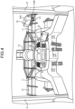
- FIG. 5 is an enlarged front view illustrating a part of the work machine 1 according to the embodiment.
- the work machine 1 includes a headlight 28, a blinker lamp 29, a first measurement device 31, and a second measurement device 32.
- the headlight 28 emits illumination light forward to illuminate an illumination area in front of the front vehicle body 2F.
- the headlight 28 is held by the housing 9.
- the headlight 28 is disposed on each of the left and right sides of the center CL of the work machine 1 in the vehicle width direction of the work machine 1.
- the headlight 28 includes a headlight 28L disposed on the left side of the center CL and a headlight 28R disposed on the right side of the center CL.
- the left headlight 28L is held by the left housing 9L.
- the right headlight 28R is held by the right housing 9R.
- the blinker lamps 29 are turned on or off to display the turning direction of the work machine 1.
- the blinker lamps 29 are held by the housing 9.
- the blinker lamps 29 are disposed on the left and right sides of the center CL of the work machine 1 in the vehicle width direction of the work machine 1.
- the blinker lamps 29 include a blinker lamp 29L disposed on the left side of the center CL and a blinker lamp 29R disposed on the right side of the center CL.
- the left blinker lamp 29L is held by the left housing 9L.
- the right blinker lamp 29R is held by the right housing 9R.
- the blinker lamps 29 are disposed outside of the headlights 28 in the vehicle width direction of the work machine 1.
- the first measurement device 31 measures a predetermined target.
- a target to be measured by the first measurement device 31 includes the working equipment 10.
- the first measurement device 31 measures the working equipment 10.
- the first measurement device 31 acquires measurement data of the working equipment 10.
- the first measurement device 31 is an imaging device that images the working equipment 10.
- the measurement data of the working equipment 10 includes image data of the working equipment 10.
- the first measurement device 31 is appropriately referred to as a first imaging device 31.
- Each of the first imaging device 31 and the second imaging device 32 includes an optical system and an image sensor on which light having passed through the optical system is incident.
- the image sensor include a couple charged device (CCD) image sensor and a complementary metal oxide semiconductor (CMOS) image sensor.
- CCD couple charged device
- CMOS complementary metal oxide semiconductor
- the first imaging device 31 and the second imaging device 32 are each disposed in the housing 9. In the vehicle width direction of the work machine 1, the first imaging device 31 and the second imaging device 32 are each disposed outside of the headlights 28. In the housing 9, the second imaging device 32 is disposed above the first imaging device 31.
- the first imaging device 31 is disposed on each of the left and right sides of the center CL of the work machine 1 in the vehicle width direction of the work machine 1.
- the first imaging device 31 is disposed in each of the left and right housings 9.
- the first imaging device 31 includes a first imaging device 31L disposed on the left side of the center CL and a first imaging device 31R disposed on the right side of the center CL.
- the second imaging device 32 is disposed on each of the left and right sides of the center CL of the work machine 1 in the vehicle width direction of the work machine 1.
- the second imaging device 32 is disposed in each of the left and right housings 9.
- the second imaging device 32 includes a second imaging device 32L disposed on the left side of the center CL and a second imaging device 32R disposed on the right side of the center CL.
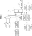
- FIG. 6 is a diagram illustrating a drive system 40 of the work machine 1 according to the embodiment.
- the drive system 40 includes an engine 41, a fuel injection device 42, a power take-off (PTO) 43, a transmission 44, a front axle 45F, a rear axle 45R, a hydraulic pump 46, a control valve 47, and a drive controller 48.
- PTO power take-off
- the engine 41 is, for example, a diesel engine.
- the fuel injection device 42 injects fuel into a cylinder of the engine 41.
- a driving force of the engine 41 is adjusted by adjusting an amount of fuel injected from the fuel injection device 42 to the engine 41.
- the power take-off 43 distributes the driving force of the engine 41 to the transmission 44 and the hydraulic pump 46.
- the driving force of the engine 41 is transmitted to the transmission 44 and the hydraulic pump 46 via the power take-off 43.
- the transmission 44 includes an input shaft to which the driving force of the engine 41 is input and an output shaft that changes a speed of the driving force input to the input shaft and outputs the changed speed of the driving force.
- the input shaft of the transmission 44 is connected to the power take-off 43.
- the output shaft of the transmission 44 is connected to each of the front axle 45F and the rear axle 45R.
- the driving force of the engine 41 is transmitted to each of the front axle 45F and the rear axle 45R via the power take-off 43 and the transmission 44.
- the transmission 44 switches a traveling direction of the work machine 1 between the forward direction and the backward direction.
- the transmission 44 includes a forward gear 44F and a reverse gear 44R.
- the forward gear 44F When the forward gear 44F is engaged, the traveling direction of the work machine 1 is determined to be the forward direction.
- the reverse gear 44R When the reverse gear 44R is engaged, the traveling direction of the work machine 1 is determined to be the reverse direction.
- the front axle 45F transmits the driving force transmitted from the transmission 44 to the front wheel 5F.
- the front wheel 5F is rotated based on the driving force transmitted from the front axle 45F.
- the rear axle 45R transmits the driving force transmitted from the transmission 44 to the rear wheel 5R.
- the rear wheel 5R is rotated based on the driving force transmitted from the rear axle 45R.
- the work machine 1 When the forward gear 44F is engaged, the work machine 1 enters a forward movable state. In a state where the forward gear 44F is engaged, the accelerator pedal 20A is operated, and the driving force of the engine 41 is transmitted to each of the front axle 45F and the rear axle 45R via the transmission 44, and thus the work machine 1 moves forward. Even in the state where the forward gear 44F is engaged, the work machine 1 does not move forward, for example, in a state where the brake pedal 20B is operated.
- the work machine 1 When the reverse gear 44R is engaged, the work machine 1 enters a reverse movable state. In the state where the reverse gear 44R is engaged, the accelerator pedal 20A is operated, and the driving force of the engine 41 is transmitted to each of the front axle 45F and the rear axle 45R via the transmission 44, and thus the work machine 1 moves reversely. Even in the state where the reverse gear 44R is engaged, the work machine 1 does not move reversely, for example, in a state where the brake pedal 20B is operated.
- the hydraulic pump 46 discharges hydraulic oil.
- the hydraulic pump 46 is a variable displacement hydraulic pump.
- the hydraulic pump 46 is driven based on a driving force of the engine 41.
- the hydraulic oil discharged from the hydraulic pump 46 is supplied to at least one of the boom cylinder 13 and the bucket cylinder 14 via the control valve 47.
- the control valve 47 controls a flow rate and a direction of the hydraulic oil supplied to each of the boom cylinder 13 and the bucket cylinder 14.
- the working equipment 10 is operated with the hydraulic oil supplied from the hydraulic pump 46 via the control valve 47.
- the drive controller 48 controls the work machine 1 based on an operation signal output from the driving operation device 20.
- the drive controller 48 includes a computer system.
- FIG. 7 is a diagram illustrating an operation of the working equipment 10 according to the embodiment.
- the working equipment 10 is a front-loading type working equipment in which the opening 12M of the bucket 12 faces forward in the excavation work.
- the boom 11 When the boom cylinder 13 extends and contracts, the boom 11 performs a raising operation or a lowering operation.
- the raising operation of the boom 11 is an operation in which the boom 11 performs a rotating operation so that the distal end of the boom 11 is separated from the ground 200.
- the boom 11 performs the raising operation.
- the lowering operation of the boom 11 is an operation in which the boom 11 performs a rotating operation so that the distal end of the boom 11 approaches the ground 200.
- the boom cylinder 13 contracts, the boom 11 performs the lowering operation.
- the bucket 12 When the bucket cylinder 14 expands and contracts, the bucket 12 performs a tilting operation or a dumping operation.
- the tilting operation of the bucket 12 is an operation in which the bucket 12 performs a rotating operation such that the distal end of the bucket 12 is separated from the ground 200 in a state in which the opening 12M of the bucket 12 faces upward.
- the bell crank 15 performs a rotating operation such that the upper end of the bell crank 15 moves forward and the lower end of the bell crank 15 moves backward.
- the bucket 12 is pulled backward by the bucket link 16 and performs the tilting operation.
- the excavation target is scooped by the bucket 12, and the excavated object is held by the bucket 12.
- the dumping operation of the bucket 12 is an operation in which the bucket 12 rotates so that the distal end of the bucket 12 approaches the ground 200 in a state in which the opening 12M of the bucket 12 faces downward.
- the bell crank 15 rotates such that the upper end of the bell crank 15 moves backward and the lower end of the bell crank 15 moves forward.
- the bucket 12 is pushed forward by the bucket link 16 and performs the dumping operation.
- the excavated object held by the bucket 12 is discharged from the bucket 12.
- FIG. 8 is a diagram illustrating an operation of the work machine 1 according to the embodiment.
- the work machine 1 performs excavation work and loading work at a work site.
- the excavation work is work for excavating an excavation target.
- the excavation target include a natural ground and a rocky mountain.
- the natural ground is a mountain formed of earth and sand placed on the ground 200.
- the rock mountain is a mountain formed of rocks or stones placed on the ground 200.
- the excavation target is a natural ground 210.
- An excavated object is a part of the natural ground 210 excavated and held by the bucket 12.
- the loading work is work for loading an excavated object excavated by the excavation work onto a loading target.
- the loading target include a haul vehicle, a hopper, and a belt conveyor.
- the loading target is a dump body 230 of a dump truck 220 that is a type of haul vehicle.
- the work machine 1 is operated by a driver so that cyclic work for repeating a series of work modes is performed.
- the cyclic work includes a plurality of work modes that are mutually related.
- the cyclic work includes traveling of the traveling apparatus 4 and an operation of the working equipment 10.
- the cyclic work includes six work modes.
- a series of work modes of the work machine 1 includes an unloaded forward mode, an excavation mode, a loading reverse mode, a loading forward mode, a loading mode, and an unloaded reverse mode.
- the order of the series of work modes is determined. After the unloaded forward mode is implemented, the excavation mode is implemented. After the excavation mode is performed, the loading reverse mode is performed. After the loading reverse mode is performed, the loading forward mode is performed. After the loading forward mode is performed, the loading mode is performed. After the loading mode is implemented, the unloaded reversing mode is implemented.
- the unloaded forward mode is a work mode in which the work machine 1 moves forward to approach the excavation target in a state where the excavated object is not held by the bucket 12.
- the work machine 1 moves forward so as to approach the natural ground 210 as indicated by an arrow M1 in FIG. 8 in a state where the excavated object is not held by the bucket 12.
- the excavation mode is a work mode in which the bucket 12 of the working equipment 10 excavates the excavation target. In the excavation mode, an excavation operation is performed.
- the bucket 12 performs a tilting operation in a state where at least a part of the bucket 12 is inserted into the natural ground 210, the natural ground 210 is excavated by the bucket 12, and the excavated object is held by the bucket 12.
- the loading reverse mode is a work mode in which the work machine 1 moves backward to be separated from the excavation target in a state where the excavated object is held by the bucket 12.
- the work machine 1 moves backward to be separated from the natural ground 210 as indicated by an arrow M2 in FIG. 8 in a state where the excavated object is held by the bucket 12.
- the loading forward mode is a work mode in which the work machine 1 moves forward to approach the loading target in a state where the excavated object is held by the bucket 12.
- the work machine 1 moves forward while swinging toward the dump truck 220 as indicated by an arrow M3 in FIG. 8 in a state where the excavated object is held by the bucket 12.
- the boom 11 performs a raising operation so that the bucket 12 is disposed above the dump body 230.
- the loading mode is a work mode in which an excavated object held by the bucket 12 of the working equipment 10 is loaded onto a loading target. In the loading mode, the loading operation is performed. After the bucket 12 is disposed above the dump body 230, the bucket 12 performs a dumping operation, so that the excavated object held by the bucket 12 is discharged from the bucket 12 and loaded into the dump body 230.
- the unloaded backward mode is a work mode in which the work machine 1 moves backward to be separated from the loading target in a state where the excavated object is not held by the bucket 12.
- the work machine 1 moves backward while swinging to be separated from the dump truck 220 as indicated by an arrow M4 in FIG. 8 in a state where the excavated object is not held by the bucket 12.
- the work machine 1 repeats the cyclic work including the unloaded forward mode, the excavation mode, the loading reverse mode, the loading forward mode, the loading mode, and the unloaded backward mode until the excavated object is loaded onto the dump body 230 with the target loading amount.
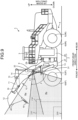
- FIG. 9 is a side view illustrating the work machine 1 that performs the loading work according to the embodiment.
- FIG. 10 is a top view illustrating the work machine 1 that performs the loading work according to the embodiment.
- the work machine 1 when an excavated object is loaded onto the dump body 230 of the dump truck 220, the work machine 1 performs the raising operation of the boom 11 such that the bucket 12 is disposed above the dump body 230. After the boom 11 performs the raising operation and the bucket 12 is disposed above the dump body 230, the work machine 1 causes the bucket 12 to perform the dumping operation.
- the bucket 12 performs a dumping operation such that the excavated object held by the bucket 12 is discharged to the dump body 230 of the dump truck 220 in a state where the boom 11 performs the raising operation.
- the first imaging device 31 images at least the bucket 12 that performs the dumping operation in order to discharge the excavated object to the dump body 230. By the dumping operation of the bucket 12, the excavated object held by the bucket 12 is discharged from the bucket 12 and loaded into the dump body 230.
- a measurement range Ra of the first imaging device 31 includes an imaging range of the first imaging device 31.
- the measurement range Ra is determined based on a first angle of view a indicating an angle of view of the optical system of the first imaging device 31.
- the first imaging device 31 images the bucket 12 that performs the dumping operation in order to discharge the excavated object to the dump body 230.
- the first imaging device 31 is fixed to the housing 9 such that the bucket 12 including the bucket teeth 18 is disposed in the measurement range Ra when the boom 11 performs the raising operation and the bucket 12 performs the dumping operation.
- a measurement range Rb of the second imaging device 32 includes an imaging range of the second imaging device 32.
- the measurement range Rb is determined based on a second angle of view ⁇ indicating an angle of view of the optical system of the second imaging device 32.
- the second imaging device 32 images at least the ground 200 in a traveling direction of the tire 6. In the embodiment, when the work machine 1 moves forward, the second imaging device 32 images the ground 200 in front of the front tires 6F.
- the second imaging device 32 is fixed to the housing 9 such that at least the ground 200 in front of the front tires 6F is disposed in the measurement range Rb when the work machine 1 moves forward.
- the second imaging device 32 is fixed to the housing 9 such that each of the front end of the front tire 6F, the ground 200 in front of the front tire 6F, and the ground 200 outside of the front tire 6F in the vehicle width direction is disposed in the measurement range Rb.
- the ground 200 in front of the front tire 6F includes the ground 200 between the front end of the front tire 6F and the rear end of the bucket 12 in the front-rear direction.
- the second angle of view ⁇ of the second imaging device 32 is wider than the first angle of view a of the first imaging device 31.
- the first imaging device 31L on the left side of the center CL images at least a left portion of the bucket 12 of the working equipment 10.
- the first imaging device 31R on the right side of the center CL images at least a right portion of the bucket 12 of the working equipment 10.
- the left portion of the bucket 12 is a portion of the bucket 12 between the left end 12E of the bucket 12 and the center CL.
- the right portion of the bucket 12 is a portion of the bucket 12 between the right end 12E of the bucket 12 and the center CL.
- the first imaging device 31L on the left side of the center CL is fixed to the left housing 9 such that the bucket teeth 181, 182, 183, 184, and 185 are disposed in the measurement range Ra when the boom 11 performs the raising operation and the bucket 12 performs the dumping operation.
- the first imaging device 31R on the right side of the center CL is fixed to the right housing 9 such that the bucket teeth 184, 185, 186, 187, and 188 are disposed in the measurement range Ra when the boom 11 performs the raising operation and the bucket 12 performs the dumping operation.
- the second imaging device 32L on the left side of the center CL images the ground 200 in front of the front tire 6F on the left side of the center CL.
- the second imaging device 32R on the right side of the center CL images the ground 200 in front of the front tire 6F on the right side of the center CL.
- the second imaging device 32L on the left side of the center CL is fixed to the left housing 9 such that the front end of the left front tire 6F, the ground 200 in front of the left front tire 6F, and the ground 200 on the left side of the left front tire 6F are disposed in the measurement range Rb.
- the second imaging device 32R on the right side of the center CL is fixed to the right housing 9 such that the front end of the right front tire 6F, the ground 200 in front of the right front tire 6F, and the ground 200 on the right side of the right front tire 6F are disposed in the measurement range Rb.
- FIG. 11 is a diagram illustrating an example of image data captured by the first imaging device 31L on the left according to the embodiment.
- FIG. 12 is a diagram illustrating an example of image data captured by the second imaging device 32R on the left according to the embodiment.
- the first imaging device 31L images the bucket 12 performing the dumping operation so that the excavated object is discharged to the dump body 230 so as to look up from below. Accordingly, as illustrated in FIG. 11 , the first imaging device 31L can simultaneously image a plurality of bucket teeth 18. In the example illustrated in FIG. 11 , the bucket teeth 181, 182, 183, 184, 185, and 186 are disposed in the measurement range Ra of the first imaging device 31.
- the second imaging device 32L images the ground 200 in front of the front tires 6F and the ground 200 on the left side so as to look down from above. Accordingly, the second imaging device 32L can image the ground 200 around the front tire 6F. For example, when there is a rolling stone 240 on the ground 200 around the front tire 6F, the second imaging device 32L can image the rolling stone 240 on the ground 200.
- FIG. 13 is a functional block diagram illustrating a monitoring system 30 according to the embodiment.
- the work machine 1 includes the monitoring system 30.
- the monitoring system 30 monitors the working equipment 10 and the ground 200 on which the work machine 1 travels.
- the monitoring system 30 includes the first imaging device 31, the second imaging device 32, the driving operation device 20, the angle sensor 90, the output device 24, the input device 25, and a monitoring controller 33.
- the first imaging device 31 includes a first imaging device 31L disposed on the left side of the center CL and a first imaging device 31R disposed on the right side of the center CL.
- the second imaging device 32 includes a second imaging device 32L disposed on the left side of the center CL and a second imaging device 32R disposed on the right side of the center CL.
- Each of the first imaging device 31, the second imaging device 32, the driving operation device 20, the angle sensor 90, the output device 24, and the input device 25 is connected to the monitoring controller 33.
- Image data captured by the first imaging device 31 is input to the monitoring controller 33.
- Image data captured by the second imaging device 32 is input to the monitoring controller 33.
- Operation data of the driving operation device 20 is input to the monitoring controller 33.
- Detection data of the angle sensor 90 is input to the monitoring controller 33.
- the input data generated by the input device 25 is input to the monitoring controller 33.
- each of the first imaging device 31 and the second imaging device 32 acquires measurement data at a predetermined sampling rate (samples per second (SPS)).
- the measurement data includes image data.
- the sampling rate includes a frame rate (frames per second (FPS)).
- Each of the first imaging device 31 and the second imaging device 32 captures image data at a predetermined frame rate.
- a moving image is captured.
- a moving image is captured.
- the monitoring controller 33 recognizes presence or absence of a defect of the working equipment 10 based on the image data captured by the first imaging device 31. When the defect of the working equipment 10 is recognized, the monitoring controller 33 causes the output device 24 to output a warning indicating that there is a defect in the working equipment 10.
- the defect of the working equipment 10 includes a defect of the bucket 12.
- the defect of the bucket 12 includes a defect of the bucket teeth 18 which are replacement members.
- the defect of the bucket teeth 18 includes a falling of the bucket teeth 18 from the bucket body 17.
- the monitoring controller 33 recognizes presence or absence of the rolling stone 240 on the ground 200 on which the work machine 1 travels based on the image data captured by the second imaging device 32. When the rolling stone 240 on the ground 200 is recognized, the monitoring controller 33 causes the output device 24 to output a warning indicating that there is the rolling stone 240 on the ground 200.
- the rolling stone 240 of the ground 200 includes the rolling stone 240 of the ground 200 in the traveling direction of the front tires 6F.
- the rolling stone 240 on the ground 200 in the traveling direction of the front tire 6F includes the rolling stone 240 on the ground 200 in front of the front tire 6F when the work machine 1 moves forward.
- the monitoring controller 33 recognizes presence or absence of a defect of the working equipment 10 and recognizes presence or absence of the rolling stone 240.
- the monitoring controller 33 may recognize presence or absence of a defect of the working equipment 10 or presence or absence of the rolling stone 240 in work different from the cyclic work.
- the monitoring controller 33 may recognize the presence or absence of a defect of the working equipment 10 in starting inspection before the work machine 1 starts the work.
- the monitoring controller 33 determines whether a reception surface of the first imaging device 31 is contaminated based on image data captured by the first imaging device 31. When it is determined that the first imaging device 31 is contaminated, the monitoring controller 33 causes the output device 24 to output a warning indicating that the reception surface of the first imaging device 31 is contaminated. When it is determined that the reception surface of the first imaging device 31 is contaminated, the monitoring controller 33 can cause the display device 24A to display data indicating a warning or cause the sounding device 24B to output a warning sound.
- the reception surface of the first imaging device 31 includes an incidence surface of the optical system of the first imaging device 31.
- the monitoring controller 33 determines whether the first imaging device 31 is contaminated in the cycle operation described with reference to FIG. 8 .
- the monitoring controller 33 may determine whether the incidence surface of the optical system of the first imaging device 31 is contaminated in work different from the cyclic work.
- the monitoring controller 33 may determine whether the incidence surface of the optical system of the first imaging device 31 is contaminated in the starting inspection before the work machine 1 starts work.
- the monitoring controller 33 includes a measurement data acquisition unit 331, a vehicle body data acquisition unit 332, a state determination unit 333, an algorithm selection unit 334, a processing unit 335, a contamination determination unit 336, an output unit 337, and an algorithm storage unit 338.
- the measurement data acquisition unit 331 acquires measurement data of the first imaging device 31 and measurement data of the second imaging device 32.
- the measurement data acquisition unit 331 acquires measurement data of the working equipment 10 measured by the first imaging device 31 from the first imaging device 31 at a predetermined sampling rate.
- the measurement data of the working equipment 10 includes image data of the working equipment 10 captured by the first imaging device 31.
- the sampling rate includes a frame rate.
- the measurement data acquisition unit 331 acquires image data of the working equipment 10 from the first imaging device 31 at a predetermined frame rate.
- the measurement data acquisition unit 331 acquires measurement data of the ground 200 measured by the second imaging device 32 from the second imaging device 32 at a predetermined sampling rate.
- the measurement data of the ground 200 includes image data of the ground 200 captured by the second imaging device 32.
- the sampling rate includes a frame rate.
- the measurement data acquisition unit 331 acquires the image data of the ground 200 from the second imaging device 32 at a predetermined frame rate.
- the measurement data acquisition unit 331 acquires image data of
- the vehicle body data acquisition unit 332 acquires vehicle body data indicating a state of the work machine 1.
- the state of the work machine 1 includes a working state of the work machine 1.
- the state of the work machine 1 includes a state of the working equipment 10 and a state of the traveling apparatus 4.
- the state of the working equipment 10 includes an attitude of the working equipment 10.
- the state of the traveling apparatus 4 includes forward movement and backward movement of the traveling apparatus 4.
- the vehicle body data includes attitude data indicating the attitude of the working equipment 10 and forward or backward data indicating forward or backward movement of the traveling apparatus 4.
- the attitude data of the working equipment 10 includes an angle of the working equipment 10.
- the angle of the working equipment 10 is detected by the angle sensor 90.
- the attitude data of the working equipment 10 includes detection data of the angle sensor 90.
- the vehicle body data acquisition unit 332 acquires detection data of the angle sensor 90 as the attitude data of the working equipment 10.
- the forward movement and the backward movement of the traveling apparatus 4 are switched by a forward or backward lever 20C of the driving operation device 20.
- the forward or backward data of the traveling apparatus 4 includes operation data of the forward or backward lever 20C.
- the vehicle body data acquisition unit 332 acquires the operation data of the forward or backward lever 20C as the forward or backward data of the traveling apparatus 4.
- the rotation sensor can detect forward movement or backward movement of the traveling apparatus 4 by detecting the rotation direction of the wheel 5.
- the vehicle body data acquisition unit 332 may acquire detection data of the rotation sensor as forward or backward data of the traveling apparatus 4.
- the vehicle body data acquisition unit 332 may acquire state data indicating a state of the drive system 40 as forward or backward data of the traveling apparatus 4.
- the drive controller 48 inputs state data indicating the state of the drive system 40 to the monitoring controller 33.
- the vehicle body data acquisition unit 332 determines the state of the drive system 40 based on the state data from the drive controller 48.
- the state of the drive system 40 includes an operating state of the transmission 44.
- the transmission 44 switches a traveling direction of the work machine 1 between the forward direction and the backward direction.
- the transmission 44 includes a forward gear 44F that operates to advance the work machine 1 and a reverse gear 44R that operates to reverse the work machine 1.
- the vehicle body data acquisition unit 332 may acquire state data indicating the state of the transmission 44 as forward or backward data of the traveling apparatus 4.
- the state determination unit 333 determines the state of the work machine 1 based on the vehicle body data acquired by the vehicle body data acquisition unit 332.
- the state determination unit 333 can determine whether the boom 11 is performing the raising operation or the lowering operation based on the attitude data of the working equipment 10 acquired by the vehicle body data acquisition unit 332.
- the state determination unit 333 can determine whether the bucket 12 is performing the tilting operation or the dumping operation based on the attitude data of the working equipment 10 acquired by the vehicle body data acquisition unit 332.
- the state determination unit 333 can determine whether the work machine 1 moves forward or backward based on the forward or backward data of the traveling apparatus 4 acquired by the vehicle body data acquisition unit 332.
- the state determination unit 333 can determine whether the bucket 12 of the working equipment 10 is disposed in the measurement range Ra of the first imaging device 31 based on the attitude data of the working equipment 10. As described above, the first imaging device 31 is fixed to the housing 9 such that the bucket 12 is disposed in the measurement range Ra when the boom 11 performs the raising operation and the bucket 12 performs the dumping operation. The state determination unit 333 can determine whether the bucket teeth 18 are disposed in the measurement range Ra of the first imaging device 31 based on the attitude data of the working equipment 10. The state determination unit 333 can determine whether the inter-tooth protectors 19 are disposed in the measurement range Ra of the first imaging device 31 based on the attitude data of the working equipment 10.
- the state of the work machine 1 may include a working mode of the work machine 1.
- the state determination unit 333 can determine whether the work mode of the work machine 1 is any one of the unloaded forward mode, the excavation mode, the loading reverse mode, the loading forward mode, the loading mode, and the unloaded backward mode based on attitude data of the working equipment 10, forward or backward data of the traveling apparatus 4, and detection data of the weight sensor.
- a pressure sensor that detects a pressure in a bottom chamber of the boom cylinder 13 is exemplified.
- the algorithm selection unit 334 selects a specific algorithm for processing measurement data acquired by the measurement data acquisition unit 331 based on the state of the work machine 1 determined by the state determination unit 333.
- the algorithm storage unit 338 stores a plurality of algorithms different from each other in advance.
- the algorithm selection unit 334 selects a specific algorithm from a plurality of algorithms stored in the algorithm storage unit 338 based on the state of the work machine 1 determined by the state determination unit 333.
- the algorithm stored in the algorithm storage unit 338 includes a first algorithm that processes image data captured by the first imaging device 31 and a second algorithm that processes image data captured by the second imaging device 32.
- the first algorithm includes an algorithm for identifying the working equipment 10 from the image data captured by the first imaging device 31.
- the first algorithm includes an algorithm for identifying the bucket teeth 18 from the image data captured by the first imaging device 31.
- the second algorithm includes an algorithm for identifying the rolling stone 240 on the ground 200 from the image data captured by the second imaging device 32.
- the algorithms include artificial intelligence (AI) algorithms.
- the first algorithm is different from the second algorithm.
- the first algorithm includes a first AI algorithm.
- the second algorithm includes a second AI algorithm.
- the first AI algorithm recognizes the bucket teeth 18 from the image data captured by the first imaging device 31 based on the first learning model generated by learning a feature of the bucket teeth 18.
- the first learning model is a learning model that has a feature of an object as an input and has the bucket teeth 18 as an output.
- the second AI algorithm is a learning model that specifies the rolling stone 240 from image data captured by the second imaging device 32 based on a second learning model generated by learning the feature of the rolling stone 240.
- the second learning model is a learning model that has the feature of the object as an input and has the rolling stone 240 as an output.
- the algorithm selection unit 334 selects the first algorithm as a specific algorithm from the first algorithm and the second algorithm stored in the algorithm storage unit 338.
- the algorithm selection unit 334 does not select the first algorithm.
- the algorithm selection unit 334 selects the second algorithm as a specific algorithm between the first and second algorithms stored in the algorithm storage unit 338.
- the algorithm selection unit 334 does not select the second algorithm.
- the processing unit 335 processes the image data acquired by the measurement data acquisition unit 331 and recognizes the target.
- the processing unit 335 processes the image data based on the specific algorithm selected by the algorithm selection unit 334 and recognizes the target.
- the processing unit 335 processes the image data of the first imaging device 31 based on the first algorithm to recognize the working equipment 10. In the embodiment, the processing unit 335 processes the image data of the first imaging device 31 based on the first algorithm, and determines presence or absence of a defect of the working equipment 10. In the embodiment, the processing unit 335 determines presence or absence of a falling off of the bucket teeth 18 from the bucket body 17 in the image data of the first imaging device 31.
- the processing unit 335 processes the image data of the second measurement device 32 based on the second algorithm to recognize the ground 200. In the embodiment, the processing unit 335 processes the image data of the second imaging device 32 based on the second algorithm and determines presence or absence of the rolling stone 240 on the ground 200. In the embodiment, the processing unit 335 determines the presence or absence of the rolling stone 240 on the ground 200 in front of the front tire 6F in the image data of the second imaging device 32.
- the processing unit 335 can efficiently recognize a plurality of targets. In a situation where the bucket 12 is disposed in the measurement range Ra of the first imaging device 31, the processing unit 335 processes the image data captured by the first imaging device 31 based on the first algorithm to recognize the bucket teeth 18. In a situation where the bucket 12 is not disposed in the measurement range Ra of the first imaging device 31, the processing unit 335 does not perform a process of recognizing the bucket teeth 18.
- the processing unit 335 processes the image data captured by the second imaging device 32 based on the second algorithm to recognize the rolling stone 240 on the ground 200 in front of the front tires 6F.
- the processing unit 335 does not perform the process of recognizing the rolling stone 240.
- the monitoring controller 33 may not always perform the process of recognizing both the bucket teeth 18 and the rolling stone 240. Therefore, a burden on the monitoring controller 33 required to monitor the bucket teeth 18 and the rolling stone 240 is reduced. Therefore, the monitoring controller 33 can efficiently monitor each of the bucket teeth 18 and the rolling stone 240.
- the contamination determination unit 336 determines whether the incidence surface of the optical system of the first imaging device 31 is contaminated based on the state of the work machine 1 determined by the state determination unit 333 and the recognition result of the working equipment 10 by the processing unit 335. There is a high possibility of earth and sand or dust being scattered at the work site of the work machine 1. As a result, there is a possibility of foreign matters adhering to the incidence surface of the optical system of the first imaging device 31. There is a possibility of the incidence surface of the optical system of the first imaging device 31 being contaminated due to the adhesion of the foreign matters.
- the contamination determination unit 336 determines that the incidence surface of the optical system of the first imaging device 31 is not contaminated.
- the contamination determination unit 336 determines that the incidence surface of the optical system of the first imaging device 31 is not contaminated.
- the contamination determination unit 336 determines that the incidence surface of the optical system of the first imaging device 31 is contaminated.
- the contamination determination unit 336 determines that the incidence surface of the optical system of the first imaging device 31 is contaminated.
- the first imaging device 31 When the incidence surface of the optical system of the first imaging device 31 is not contaminated, the first imaging device 31 can correctly image the bucket teeth 18 by disposing the bucket teeth 18 in the measurement range Ra of the first imaging device 31. Therefore, the processing unit 335 can correctly identify the bucket teeth 18. Conversely, when the incidence surface of the optical system of the first imaging device 31 is contaminated, there is a high possibility that the first imaging device 31 cannot correctly image the bucket teeth 18 even when the bucket teeth 18 are disposed in the measurement range Ra of the first imaging device 31. Therefore, there is a high possibility that the processing unit 335 cannot identify the bucket teeth 18.
- the contamination determination unit 336 determines that the incidence surface of the optical system of the first imaging device 31 is not contaminated.
- the contamination determination unit 336 determines that the incidence surface of the optical system of the first imaging device 31 is contaminated.
- the contamination determination unit 336 may determine whether the incidence surface of the optical system of the second imaging device 32 is contaminated based on a recognition result of the rolling stone 240 by the processing unit 335.
- the rolling stone 240 is disposed in the measurement range Rb of the second imaging device 32, and thus the second imaging device 32 can correctly image the rolling stone 240. Therefore, the processing unit 335 can correctly identify the rolling stone 240.
- the contamination determination unit 336 determines that the incidence surface of the optical system of the second imaging device 32 is not contaminated.
- the contamination determination unit 336 determines that the incidence surface of the optical system of the second imaging device 32 is contaminated.
- the output unit 337 causes the output device 24 to output the recognition result of the object recognized by the processing unit 335.
- the output unit 337 causes the output device 24 to output the determination result of the presence or absence of contamination determined by the contamination determination unit 336.
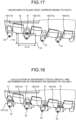
- FIGS. 14 , 15 , 16 , 17, and 18 is a diagram illustrating a defect determination method of the working equipment 10 according to the embodiment.
- a method of determining presence or absence of a defect of the bucket teeth 18 based on the image data captured by the first imaging device 31L on the left side of the center CL will be described.
- the algorithm selection unit 334 selects the first algorithm based on the detection data of the angle sensor 90 acquired by the vehicle body data acquisition unit 332.
- the first imaging device 31L images the bucket 12 that performs the dumping operation in order to discharge the excavated object to the dump body 230.
- the measurement data acquisition unit 331 acquires the image data of the bucket 12 from the first imaging device 31L.
- the plurality of bucket teeth 18 (181, 182, 183, 184, and 185) are disposed in a recognition range 50 of the image data. Each of the plurality of bucket teeth 18 is attached to the bucket body 17 so that from bucket body 17 protrudes.
- the processing unit 335 processes the image data acquired by the measurement data acquisition unit 331 based on the first algorithm and recognizes each of the plurality of bucket teeth 18 in the recognition range 50 of the image data.
- the processing unit 335 estimates positions of a root 51 and a blade edge 52 of each of the plurality of bucket teeth 18.
- the root 51 is a proximal end of the bucket teeth 18.
- the root 51 includes a boundary between the bucket teeth 18 and the bucket body 17.
- the blade edge 52 is a distal end of the bucket teeth 18.
- the processing unit 335 estimates the root 51 and the blade edge 52 using the first AI algorithm that analyzes input data and outputs output data.
- the processing unit 335 may estimate the positions of the root 51 and the blade edge 52 as the center where the probability is equal to or greater than a predetermined threshold using the first AI algorithm that outputs the probability of the certainty of the root 51 and the blade edge 52 based on the input data.
- the processing unit 335 may use a first AI algorithm that directly estimates the position of the root 51 and the position of the blade edge 52 based on the input data.
- the processing unit 335 calculates a distance G1 between the root 51 of the bucket teeth 181 and the root 51 of the bucket teeth 182, a distance G2 between the root 51 of the bucket teeth 182 and the root 51 of the bucket teeth 183, and a distance G3 between the root 51 of the bucket teeth 183 and the root 51 of the bucket teeth 184.
- the processing unit 335 calculates a reference inter-tooth distance G based on the distances G1, G2, and G3.
- the reference inter-tooth distance G is a median value of the distances G1, G2, and G3.
- the processing unit 335 searches for the blade edge 52 corresponding to the root 51.
- the root 51 and the blade edge 52 corresponding to the root 51 include a proximal end and a distal end of one bucket tooth 18.
- the processing unit 335 sets a search range 53 with the root 51 as a reference, and searches the blade edge 52 in the search range 53.
- the search range 53 is set in a rectangular shape in the image data. As illustrated in FIG. 17 , a dimension of the search range 53 in the up-down direction in the image data is defined as [ ⁇ G], and a dimension of the search range 53 in the horizontal direction in the image data is defined as [ ⁇ G].
- ⁇ and ⁇ are predetermined fixed values.
- the bucket 12 appears largely in the image data captured by the first imaging device 31L when a distance between the first imaging device 31L and the bucket 12 is short. In the image data captured by the first imaging device 31L when the distance between the first imaging device 31L and the bucket 12 is long, the bucket 12 appears small. When the size of the bucket 12 is different in the image data, there is a possibility that the processing unit 335 cannot search for the blade edge 52 corresponding to the root 51. In the embodiment, the search range 53 is set based on the reference inter-tooth distance G. Accordingly, the processing unit 335 can search for the blade edge 52 corresponding to the root 51 regardless of the distance between the first imaging device 31L and the bucket 12.
- the processing unit 335 After the processing unit 335 searches for the blade edge 52 corresponding to each of the plurality of roots 51, as illustrated in FIG. 18 , the processing unit 335 calculates a distance L1 between the root 51 of the bucket tooth 181 and the blade edge 52, a distance L2 between the root 51 of the bucket tooth 182 and the blade edge 52, a distance L3 between the root 51 of the bucket tooth 183 and the blade edge 52, and a distance L4 between the root 51 of the bucket tooth 184 and the blade edge 52.
- the distance L1 corresponds to a protrusion amount of the bucket tooth 181 from the bucket body 17.
- the distance L2 corresponds to a protrusion amount of the bucket tooth 182 from the bucket body 17.
- the distance L3 corresponds to a protrusion amount of the bucket tooth 183 from the bucket body 17.
- the distance L4 corresponds to a protrusion amount of the bucket tooth 184 from the bucket body 17.
- the processing unit 335 calculates the reference tooth length L based on the distances L1, L2, L3, and L4.
- the reference tooth length L is a median value of the distances L1, L2, L3, and L4.
- the processing unit 335 may calculate distances L5, L6, L7, and L8 corresponding to the four bucket teeth 185, 186, 187, and 188 by a similar method based on the image data captured by the first imaging device 31R on the right side of the center CL and may calculate the reference tooth length L based on the distances L1, L2, L3, L4, L5, L6, L7, and L8.
- the processing unit 335 determines a dimension threshold related to the protrusion amounts of the bucket teeth 18 from the bucket body 17 based on the reference tooth length L.
- the dimension threshold is defined as [ ⁇ L]. ⁇ is a predetermined fixed value. In this way, in the embodiment, the processing unit 335 determines the dimension threshold based on the protrusion amounts (L1, L2, L3, and L4) of the plurality of bucket teeth 18 (181, 182, 183, and 184) from the bucket body 17.
- the processing unit 335 determines whether there is a defect in the bucket teeth 18 (181, 182, 183, and 184) based on the dimension threshold. When the protrusion amounts of the bucket teeth 18 from the bucket body 17 are less than the dimension threshold, the processing unit 335 determines that there is a defect in the bucket teeth 18. When the protrusion amounts of the bucket teeth 18 from the bucket body 17 are equal to or greater than the dimension threshold, the processing unit 335 determines that there is no defect in the bucket teeth 18.
- the processing unit 335 determines that the bucket teeth 18 are detached from the bucket body 17 when the protrusion amount of the bucket teeth 18 is less than the dimension threshold, and determines that the bucket teeth 18 are not detached from the bucket body 17 when the protrusion amounts of the bucket teeth 18 are equal to or greater than the dimension threshold.
- the bucket 12 appears largely in the image data captured by the first imaging device 31L when a distance between the first imaging device 31L and the bucket 12 is short. In the image data captured by the first imaging device 31L when the distance between the first imaging device 31L and the bucket 12 is long, the bucket 12 appears small. When the size of the bucket 12 is different in the image data, there is a possibility that the processing unit 335 cannot correctly determine whether there is a defect in the bucket teeth 18. In the embodiment, the dimension threshold is determined based on the reference tooth length L. Accordingly, the processing unit 335 can determine whether there is a defect in the bucket teeth 18 regardless of the distance between the first imaging device 31L and the bucket 12.
- the processing unit 335 classifies the measurement data into a plurality of samples based on a determination result indicating whether there is a defect in the bucket teeth 18.
- the processing unit 335 classifies the measurement data determined to have no defect into soundness determination samples.
- the processing unit 335 classifies the measurement data determined to have a defect into defect determination samples.
- the processing unit 335 classifies the measurement data in which the bucket teeth 18 cannot be recognized into undetermined samples.
- the processing unit 335 counts the number of soundness determination samples indicating the measurement data determined to have no defect.
- the processing unit 335 counts the number of defect determination samples indicating the measurement data determined to have a defect.
- the processing unit 335 counts the number of undetermined samples indicating the measurement data in which the bucket teeth 18 cannot be recognized.
- the measurement data is image data
- the samples classified by the processing unit 335 are frames.
- the soundness determination sample is appropriately referred to as a soundness determination frame
- the defect determination sample is appropriately referred to as a defect determination frame
- the undetermined sample is appropriately referred to as an undetermined frame.
- FIG. 19 is a diagram illustrating an example of a soundness determination frame according to an embodiment.
- each of the distance L1 indicating the protrusion amount of the bucket tooth 181, the distance L2 indicating the protrusion amount of the bucket tooth 182, the distance L3 indicating the protrusion amount of the bucket tooth 183, and the distance L4 indicating the protrusion amount of the bucket tooth 184 is equal to or greater than the dimension threshold.
- the processing unit 335 determines that the bucket teeth 18 are not defective.
- the processing unit 335 classifies the image data determined to have no defect into a soundness determination frame.
- FIG. 20 is a diagram illustrating an example of the defect determination frame according to the embodiment.
- the distance L2 indicating the protrusion amount of the bucket tooth 182 is less than the dimension threshold.
- the processing unit 335 determines that the bucket tooth 182 is defective.
- the processing unit 335 classifies the image data determined to have a defect into a defect determination frame.
- the method of determining whether the bucket teeth 18 falls off based on the image data captured by the first imaging device 31L on the left side of the center CL has been described above. The same applies to a method of determining whether the bucket teeth 18 falls off based on image data captured by the first imaging device 31R on the right side of the center CL.
- the processing unit 335 determines whether the four bucket teeth 185,186,187, and 188 fall off based on the image data acquired by the measurement data acquisition unit 331 from the first imaging device 31R.
- the output unit 337 causes the display device 24A to display a symbol 60 indicating the bucket teeth 18.
- the output unit 337 changes a display form of the symbol 60 based on presence or absence of the defect of the bucket teeth 18.
- FIG. 21 is a diagram illustrating an example of the symbol 60 indicating the bucket teeth 18 displayed on the display device 24A according to the embodiment.
- the output unit 337 causes the display device 24A to display the symbol 60 indicating the bucket teeth 18 that cannot be recognized in the first display mode.
- the output unit 337 causes the display device 24A to display the symbol 60 indicating the bucket teeth 18 determined to have no defect in the second display mode.
- the output unit 337 causes the display device 24A to display the symbol 60 indicating the bucket teeth 18 determined to have the defect in the third display mode.
- the output unit 337 displays the symbol 60 indicating the bucket teeth 18 that cannot be recognized by the processing unit 335 in first color.
- the first color is, for example, gray.
- the output unit 337 displays the symbol 60 indicating the bucket teeth 18 determined to have no defect in second color.
- the second color is, for example, green.
- the output unit 337 displays a symbol indicating the bucket teeth 18 determined to have a defect in third color.
- the third color is, for example, red.
- the output unit 337 When there is a defect determination frame, the output unit 337 causes the output device 24 to output a warning indicating that there is the defect determination frame.
- the output unit 337 changes the form of the warning output from the output device 24 based on the number of defect determination frames counted by the processing unit 335.
- the output unit 337 causes the output device 24 to output the warning in the first mode when the number of defect determination frames is less than a sample threshold, and causes the output device 24 to output a warning in the second mode when the number of defect determination frames is equal to or greater than the sample threshold.
- the sample threshold is a predetermined value.
- the output device 24 includes the display device 24A that displays the symbol 60 indicating the bucket teeth 18 and the sounding device 24B that generates a warning sound.
- the output unit 337 may cause the display device 24A to display the display data in the first mode when the number of defect determination frames is less than the sample threshold, and may cause the display device 24A to display the display data in the second mode when the number of defect determination frames is equal to or greater than the sample threshold.
- the output unit 337 may cause the sounding device 24B to generate the warning sound in the first mode when the number of defect determination frames is less than the sample threshold, and may cause the sounding device 24B to generate the warning sound in the second mode when the number of defect determination frames is equal to or greater than the sample threshold.
- FIG. 22 is a diagram illustrating a relationship between a defect determination frame and a form of a warning according to the embodiment. Presence or absence of the defect determination frame is determined at a predetermined frame rate. In the example illustrated in FIG. 22 , presence or absence of a defect determination frame is determined at intervals of 0.2 [sec.]. In FIG. 22 , a "normal" frame indicates a soundness determination frame or an undetermined frame. In FIG. 22 , a "defect" frame includes a defect determination frame. In the example illustrated in FIG. 22 , the sample threshold is 2.
- the warning sound is not output from the sounding device 24B.
- the symbol 60 indicating the unrecognizable bucket teeth 18 is displayed in the first display mode on the display device 24A.
- the symbol 60 indicating the bucket teeth 18 determined to have no defect is displayed in the second display mode on the display device 24A.
- the plurality of bucket teeth 18 are attached to the bucket body 17. In the embodiment, eight bucket teeth 18 are disposed at intervals in the vehicle width direction.
- the display device 24A displays the plurality of symbols 60 based on the positions of the plurality of bucket teeth 18. On the display device 24A, eight symbols 60 are displayed at intervals in accordance with the positions of the plurality of bucket teeth 181, 182, 183, 184, 185, 186, 187, and 188.
- the moving image includes only undetermined frames
- the eight symbols 60 are all displayed in the first display mode.
- the moving image includes only the soundness determination frame
- the eight symbols 60 are all displayed in the second display mode.
- the output unit 337 when there is one defect determination frame in the moving image, the output unit 337 causes the sounding device 24B to output a first warning sound. When there are two defect determination frames in the moving image captured by the first imaging device 31, the output unit 337 causes the sounding device 24B to output a second warning sound.
- the output unit 337 causes the output device 24 to output a warning in the first mode when each of the number of pieces of continuously acquired image data less than the sample threshold is determined to be the defect determination frame by the measurement data acquisition unit 331.
- the output unit 337 causes the output device 24 to output a warning in the second mode when each of the number of pieces of continuously acquired image data equal to or greater than the sample threshold is determined to be the defect determination frame by the measurement data acquisition unit 331.
- the output unit 337 causes the sounding device 24B to output the first warning sound. That is, when the image data acquired before and after the defect determination frame is the soundness determination frame or the undetermined frame, the output unit 337 causes the sounding device 24B to output the first warning sound.
- the output unit 337 causes the sounding device 24B to output a second warning sound. That is, when the defect determination frames continue at least twice, the output unit 337 causes the sounding device 24B to output the second warning sound.
- the output unit 337 may cause the sounding device 24B to output the second warning sound.
- sample threshold may be any number of three or more, for example.
- the form of the warning includes a volume of a warning sound.
- the output of the warning in the first mode includes generation of a warning sound at a first volume from the sounding device 24B.
- the output of the warning in the second mode includes generation of a warning sound at a second volume greater than the first volume from the sounding device 24B. In the example illustrated in FIG. 22 , the volume of the second warning sound is greater than the volume of the first warning sound.
- the symbol 60 indicating the bucket teeth 18 determined to have a defect is displayed in the third display mode on the display device 24A.
- the output unit 337 displays the symbol 60 indicating the bucket teeth 18 determined to have a defect and the symbol 60 indicating the bucket teeth 18 determined to have no defect in different display forms. In the example illustrated in FIG.
- the output unit 337 displays the symbol indicating the bucket tooth 184 determined to have a defect in the third display mode and displays the symbol indicating the bucket teeth 181, 182, 183, 185, 186, 187, and 188 determined to have no defect in the second display mode.
- the algorithm selection unit 334 selects the second algorithm based on the operation data of the forward or backward lever 20C acquired by the vehicle body data acquisition unit 332.
- the processing unit 335 sets a determination reference for determining presence or absence of the rolling stone 240 on the ground 200 in the image data.
- the processing unit 335 sets a warning reference when a warning is output from the output device 24.
- FIG. 23 is a diagram illustrating a determination reference according to the embodiment.
- the references include dimensions of the rolling stone 240 of the image data.
- the dimensions of the rolling stone 240 include the number of pixels of the rolling stone 240 in the image data.
- thresholds related to the dimensions of the rolling stone 240 are set.
- the thresholds related to the dimension of the rolling stone 240 include a threshold Px related to the dimension of the rolling stone 240 in the horizontal direction and a threshold Py related to the dimension of the rolling stone 240 in the vertical direction.
- the algorithm storage unit 338 stores a standard value (initial value) related to the determination reference.
- the standard value is a recommended value related to a threshold related to the dimension of the rolling stone 240.
- the processing unit 335 sets the determination reference based on the standard value.
- the processing unit 335 sets the threshold related to the dimension of the rolling stone 240 based on the standard value.
- the threshold is a standard value.
- FIG. 24 is a diagram illustrating a warning reference according to the embodiment.
- the warning reference includes a warning area 36 set on at least a part of the ground 200.
- the setting of the warning reference includes setting of dimensions of the warning area 36.
- the dimensions of the warning area 36 include the number of pixels of the warning area in the image data. As illustrated in FIG. 24 , a dimension Qx of the warning area 36 in the horizontal direction and a dimension Qy of the warning area 36 in the vertical direction are set in the image data.
- the setting of the warning area 36 includes setting of the position of the warning area 36.
- the setting of the position of the warning area 36 includes setting of the position of the warning area 36 in the image data.
- the processing unit 335 sets the warning area 36 in a part of the ground 200 in front of the front tire 6F.
- the algorithm storage unit 338 stores a standard value (initial value) related to the warning reference.
- the standard value is a recommended value related to the dimensions and position of the warning area 36.
- the processing unit 335 sets a warning reference based on the standard value. In the embodiment, the processing unit 335 sets the dimensions and position of the warning area 36 in the image data based on the standard value.
- the processing unit 335 acquires input data from the input device 25.
- the driver can change the setting of the determination reference or the setting of the warning reference by operating the input device 25.
- the processing unit 335 sets a determination reference based on the input data.
- the processing unit 335 sets a warning reference based on the input data.
- FIG. 25 is a diagram illustrating an example of a setting screen of a determination reference and a warning reference according to the embodiment.
- the processing unit 335 causes the display device 24A to display the setting screen of the determination reference.
- the processing unit 335 causes the display device 24A to display the setting screen of the warning reference.
- the driver can perform at least one of a change in the setting of the determination reference and a change in the setting of the warning reference by operating the input device 25 while viewing the setting screen.
- the measurement data acquisition unit 331 acquires the measurement data of the ground 200 from the second imaging device 32 at a predetermined sampling rate. As described above, the measurement data of the ground 200 includes image data of the ground 200 captured by the second imaging device 32. The sampling rate includes a frame rate. The measurement data acquisition unit 331 acquires the image data of the ground 200 from the second imaging device 32 at a predetermined frame rate. The measurement data acquisition unit 331 acquires image data of the ground 200 in front of the front tires 6F.
- the processing unit 335 determines presence or absence of the rolling stone 240 on the ground 200 based on the image data acquired by the measurement data acquisition unit 331.
- the processing unit 335 determines presence or absence of the rolling stone 240 on the ground 200 in the image data.
- the processing unit 335 determines the presence or absence of the rolling stone 240 on the ground 200 in front of the front tire 6F in the image data.
- the processing unit 335 uses a second AI algorithm that analyzes input data and outputs output data to determine the presence or absence of the rolling stone 240.
- the processing unit 335 determines the presence or absence of the rolling stone 240 on the ground 200 in the image data based on the determination reference.
- the processing unit 335 determines that there is the rolling stone 240 when the dimensions of the rolling stone 240 are greater than thresholds (Px, Py), and determines that there is no rolling stone 240 when the dimensions of the rolling stone 240 are equal to or less than the thresholds (Px, Py).
- the processing unit 335 may determine that there is the rolling stone 240 when the dimension of the rolling stone 240 exceeds one of the thresholds Px and Py.
- the processing unit 335 may determine that there is the rolling stone 240 when the dimensions of the rolling stone 240 exceed both the threshold Px and the threshold Py.
- the output unit 337 causes the output device 24 to output a warning based on the presence or absence of the rolling stone 240 on the ground 200 in front of the front tire 6F.
- the output unit 337 causes the output device 24 to output a warning based on the determination of the presence or absence of the rolling stone 240 by the processing unit 335 and the relationship between the rolling stone 240 and the warning standard.
- the warning reference includes the warning area 36 set on at least a part of the ground 200.
- the warning area 36 is set in a part of the ground 200 in front of the front tires 6F.
- the output unit 337 causes the output device 24 to output a warning based on a positional relationship between the rolling stone 240 and the warning area 36.
- the output unit 337 causes the output device 24 to output a warning indicating that there is the rolling stone 240 in the warning area 36.
- FIG. 26 is a flowchart illustrating a monitoring method according to the embodiment.
- the measurement data acquisition unit 331 acquires image data from each of the first imaging device 31 and the second imaging device 32 (Step S1).
- the vehicle body data acquisition unit 332 acquires vehicle body data indicating a state of the work machine 1.
- the vehicle body data acquisition unit 332 acquires detection data of the angle sensor 90 and operation data of the forward and backward lever 20C as the vehicle body data (Step S2).
- the state determination unit 333 determines whether the bucket 12 of the working equipment 10 is disposed in the measurement range Ra of the first measurement device 31 based on the detection data of the angle sensor 90 acquired in Step S2 (Step S3).
- Step S3 when it is determined that the bucket 12 of the working equipment 10 is disposed in the measurement range Ra of the first measurement device 31 (Step S3: Yes), the state determination unit 333 determines whether the work machine 1 moves forward based on the operation data of the forward or backward lever 20C acquired in Step S2 (Step S4).
- Step S4 when it is determined that the work machine 1 has moved forward (Step S4: Yes), the algorithm selection unit 334 selects the first and second algorithms (Step S5).
- Step S4 When it is determined in Step S4 that the work machine 1 has not moved forward (Step S4: No), the algorithm selection unit 334 selects the first algorithm (Step S6) .
- Step S3 When it is determined in Step S3 that the bucket 12 of the working equipment 10 is not disposed in the measurement range Ra of the first measurement device 31 (Step S3: No), the state determination unit 333 determines whether the work machine 1 has moved forward based on the operation data of the forward or backward lever 20C acquired in Step S2 (Step S7).
- Step S7 When it is determined in Step S7 that the work machine 1 has moved forward (Step S7: Yes), the algorithm selection unit 334 selects the second algorithm (Step S8).
- Step S5 the processing unit 335 processes the image data captured by the first imaging device 31 based on the first algorithm and recognizes the bucket 12 of the working equipment 10 (Step S9).
- the contamination determination unit 336 determines whether the bucket teeth 18 are recognized by the processing unit 335 in Step S9 (Step S10).
- Step S10 When it is determined in Step S10 that the bucket teeth 18 are recognized (Step S10: Yes), the processing unit 335 determines whether the bucket teeth 18 are defective (Step S11).
- Step S11 When it is determined in Step S11 that the bucket teeth 18 are defective (Step S11: Yes), the output unit 337 causes the output device 24 to output a warning indicating that the bucket teeth 18 are defective (Step S12).
- Step S11 When it is determined in Step S11 that the bucket teeth 18 are not defective (Step S11: No), no warning is output from the output device 24 (Step S13).
- the warning sound is not output from the sounding device 24B.
- the symbol 60 indicating the unrecognizable bucket teeth 18 is displayed in the first display mode on the display device 24A.
- the symbol 60 indicating the bucket teeth 18 determined to have no defect is displayed in the second display mode on the display device 24A.
- the first warning sound is output from the sounding device 24B.
- the second warning sound is output from the sounding device 24B.
- Step S10 When it is determined in Step S10 that the bucket teeth 18 are not recognized (Step S10: No), the contamination determination unit 336 determines that the incidence surface of the optical system of the first imaging device 31 is contaminated. When it is determined that the incidence surface of the optical system of the first imaging device 31 is contaminated, the output unit 337 causes the output device 24 to output a warning indicating that the incidence surface of the optical system of the first imaging device 31 is contaminated (Step S14).
- Step S5 the processing unit 335 processes the image data captured by the second imaging device 32 based on the second algorithm and recognizes the ground 200 (Step S15).
- the processing unit 335 determines whether there is the rolling stone 240 on the ground 200 in front of the front tire 6F (Step S16).
- Step S16 When it is determined in Step S16 that there is the rolling stone 240 on the ground 200 in front of the front tire 6F (Step S16: Yes), the output unit 337 causes the output device 24 to output a warning indicating that there is the rolling stone 240 (Step S17).
- Step S16 When it is determined in Step S16 that there is no rolling stone 240 (Step S16: No), no warning is output from the output device 24 (Step S13).
- Step S18 After any one of Step S12, Step S13, Step S14, and Step S17 is processed or when it is determined that the work machine 1 has not moved forward in Step S7, the processing unit 335 determines whether the monitoring processing ends (Step S18).
- Step S18 When it is determined in Step S18 that the monitoring process continues (Step S18: No), the process returns to Step S1 and Step S2.
- Step S18 When it is determined in Step S18 that the monitoring process ends (Step S18: Yes), the monitoring process ends.
- FIG. 27 is a diagram illustrating an example of the display device 24A according to an embodiment.
- the output unit 337 causes the display device 24A to display a target image 37 indicating the ground 200 generated based on the image data acquired by the measurement data acquisition unit 331.
- the target image 37 includes a target image 37L indicating image data captured by the second imaging device 32L on the left side and a target image 37R indicating image data captured by the second imaging device 32R on the right side.
- the target image 37L and the target image 37R are displayed side by side on a display screen of the display device 24A.
- the target image 37L and the target image 37R are simultaneously displayed on the display screen of the display device 24A.
- the target image 37L is displayed in the left region of the display screen of the display device 24A.
- the target image 37R is displayed in the right region of the display screen of the display device 24A.
- the output unit 337 causes the display device 24A to display an area image 360 indicating the warning area 36.
- the output unit 337 superimposes the area image 360 on the target image 37 to display the area image on the display device 24A.
- the area image 360 indicating the warning area 36 set to include the ground 200 in front of the left front tire 6F is displayed on the display device 24A with being superimposed on the target image 37L.
- the area image 360 indicating the warning area 36 set to include the ground 200 in front of the right front tire 6F is displayed on the display device 24A with being superimposed on the target image 37R.
- the output unit 337 causes the display device 24A to display a symbol 70 indicating front tire 6F.
- the symbol 70 includes a symbol 70L indicating the left front tire 6F and a symbol 70R indicating the right front tire 6F.
- the output unit 337 causes the output device 24 to output a warning indicating that there is the rolling stone 240 on the ground 200 in front of the front tire 6F.
- the output of a warning to the output device 24 includes display of a warning image indicating that there is the rolling stone 240 on the ground 200 in front of the front tires 6F by the display device 24A.
- the output of the warning to the output device 24 includes generation of a warning sound indicating that there is the rolling stone 240 on the ground 200 in front of the front tire 6F by the sounding device 24B.
- the warning image includes a frame image 80 displayed to surround the rolling stone 240 in the target image 37, a frame image 81 displayed at an edge of the target image 37, and a background image 82 of the symbol 70.
- the output unit 337 causes the display device 24A to display the frame image 80 such that the rolling stone 240 is emphasized.
- the rolling stone 240 of the target image 37L is disposed outside of the warning area 36.
- the output unit 337 causes the display device 24A to display a frame image 80L of the first mode.
- the processing unit 335 determines that there is the rolling stone 240 is inside the warning area 36
- the output unit 337 causes the display device 24A to display a frame image 80R of the second mode different from the first mode.
- the output unit 337 displays each of the frame image 80L and the frame image 80R on the display device 24A such that the rolling stone 240 disposed inside the warning area 36 is emphasized more than the rolling stone 240 disposed outside of the warning area 36.
- the frame image 80R is displayed with a solid line
- the frame image 80L is displayed with a dotted line.
- the frame image 80R may be displayed in the first color
- the frame image 80L may be displayed in the second color.
- red is exemplified.
- green is exemplified.
- the output unit 337 causes the display device 24A to display the frame image 81 such that the target image 37 in which there is at least a part of the rolling stone 240 inside the warning area 36 is emphasized.
- the rolling stone 240 displayed in the target image 37R inside the warning area 36.
- the output unit 337 causes the display device 24A to display the frame image 81 such that the target image 37R is emphasized more than the target image 37L.
- the output unit 337 causes the display device 24A to display the background image 82 such that the front tire 6F having a high possibility of passing over the rolling stone 240 is emphasized.
- the output unit 337 causes the display device 24A to display the background image 82 of the symbol 70R such that the right front tire 6F having a high possibility of passing over the rolling stone 240 is emphasized.
- the output unit 337 can the display device 24A to display the background image 82 of the symbol 70L such that the left front tire 6F having a high possibility of passing over the rolling stone 240 is emphasized.
- the output unit 337 causes the display device 24A to display a symbol 60 indicating the bucket teeth 18.
- the output unit 337 displays the plurality of symbols 60 based on the positions of the plurality of bucket teeth 18.
- the symbols 60 include a symbol 61 indicating the bucket tooth 181, a symbol 62 indicating the bucket tooth 182, a symbol 63 indicating the bucket tooth 183, a symbol 64 indicating the bucket tooth 184, a symbol 65 indicating the bucket tooth 185, a symbol 66 indicating the bucket tooth 186, a symbol 67 indicating the bucket tooth 187, and a symbol 68 indicating the bucket tooth 188.
- the plurality of symbols 60 are displayed in an upper area of the display screen of the display device 24A.
- the symbol 61 is displayed on the leftmost side
- the symbol 62 is located on the left side next to the symbol 61
- the symbol 63 is located on the left side next to the symbol 62
- the symbol 64 is located on the left side next to the symbol 63
- the symbol 65 is located on the left side next to the symbol 64
- the symbol 66 is located on the left side next to the symbol 65
- the symbol 67 is located on the left side next to the symbol 66
- the symbol 68 is located on the rightmost side.
- FIG. 27 illustrates an example in which the processing unit 335 cannot recognize the eight bucket teeth 18 and the eight symbols 60 are displayed in the first display form.
- the output unit 337 displays the eight symbols 60 in the first display form as illustrated in FIG. 27 .
- FIG. 28 is a diagram illustrating an example of the display device 24A according to an embodiment.
- FIG. 28 is a diagram illustrating an extracted upper region of the display device 24A.
- FIG. 28 illustrates examples of the symbols 60 when the processing unit 335 determines presence or absence of a defect of each of the eight bucket teeth 18.
- the output unit 337 changes the display form of the symbols 60 based on the presence or absence of the defect of the bucket teeth 18.
- the output unit 337 displays the symbol 60 indicating the bucket teeth 18 determined to have a defect and the symbol 60 indicating the bucket teeth 18 determined to have no defect in different display forms. As illustrated in FIG.
- the output unit 337 displays the symbol 64 indicating the bucket tooth 184 determined to have a defect in the third display mode, and displays symbols 61, 62, 63, 65, 66, 67, and 68 indicating the bucket teeth 181, 182, 183, 185, 186, 187, and 188 determined to have no defect in the second display mode.
- the output unit 337 causes the display device 24A to display the symbol 64 in the third color and causes the display device 24A to display the symbols 61, 62, 63, 65, 66, 67, and 68 in the second color.
- the third color is, for example, red.
- the second color is, for example, green.
- FIG. 29 is a block diagram illustrating a computer system 1000 according to an embodiment.
- the computer system 1000 includes a processor 1001 such as a central processing unit (CPU), a main memory 1002 including a nonvolatile memory such as a read only memory (ROM) and a volatile memory such as a random access memory (RAM), a storage 1003, and an interface 1004 including an input/output circuit.
- the functions of the above-described monitoring controller 33 and drive controller 48 are stored in the storage 1003 as a computer program.
- the processor 1001 reads the computer program from the storage 1003, loads the computer program in the main memory 1002, and executes the above-described processes according to the program.
- the computer program may be distributed to the computer system 1000 via a network.
- the computer program or the computer system 1000 can execute: acquiring measurement data of the first measurement device 31 and the second measurement device 32 that are mounted on the work machine 1 and measure a target; acquiring vehicle body data indicating a state of the work machine 1; determining the state of the work machine 1 based on the vehicle body data; selecting a specific algorithm for processing the measurement data based on the determined state of the work machine 1; processing the measurement data based on the selected specific algorithm to recognize the target; and causing an output device to output a recognition result of the target.
- the monitoring system 30 of the work machine 1 includes the measurement data acquisition unit 331 that is mounted on the work machine 1 and acquires the image data of the first imaging device 31 and the second imaging device 32 that measure the target, the vehicle body data acquisition unit 332 that acquires the vehicle body data indicating the state of the work machine 1, the state determination unit 333 that determines the state of the work machine 1 based on the vehicle body data, the algorithm selection unit 334 that selects a specific algorithm for processing the image data based on the state of the work machine 1 determined by the state determination unit 333, the processing unit 335 that processes the image data based on the specific algorithm selected by the algorithm selection unit 334 and recognizes the target, and the output unit 337 that causes the output device 24 to output the recognition result of the target recognized by the processing unit 335.
- the processing unit 335 can efficiently recognize a plurality of targets. In a situation where the bucket 12 is disposed in the measurement range Ra of the first imaging device 31, the processing unit 335 processes the image data captured by the first imaging device 31 based on the first algorithm to recognize the bucket teeth 18. In a situation where the bucket 12 is not disposed in the measurement range Ra of the first imaging device 31, the processing unit 335 does not perform a process of recognizing the bucket teeth 18.
- the processing unit 335 processes the image data captured by the second imaging device 32 based on the second algorithm to recognize the rolling stone 240 on the ground 200 in front of the front tires 6F.
- the processing unit 335 does not perform the process of recognizing the rolling stone 240.
- the monitoring controller 33 may not always perform the process of recognizing both the bucket teeth 18 and the rolling stone 240. Therefore, a burden on the monitoring controller 33 required to monitor the bucket teeth 18 and the rolling stone 240 is reduced. Therefore, the monitoring controller 33 can efficiently monitor each of the bucket teeth 18 and the rolling stone 240.
- each of the first imaging device 31 and the second imaging device 32 is disposed in the housing 9 holding the headlight 28. At least one of the first imaging device 31 and the second imaging device 32 may be disposed in a portion of the work machine 1 different from the housing 9.
- the second imaging device 32 is disposed above the first imaging device 31. At least a part of the second imaging device 32 may be disposed at the same position as the first imaging device 31 in the up-down direction. The second imaging device 32 may be disposed below the first imaging device 31.
- the defect of the bucket teeth 18 is falling off of the bucket teeth 18 from the bucket body 17.
- the defect of the bucket teeth 18 may be abrasion of the bucket teeth 18 or breakage of the bucket teeth 18.
- the processing unit 335 monitors a defect of the bucket teeth 18 as the replacement member.
- the processing unit 335 may monitor a defect of the inter-tooth protector 19 as a replacement member.
- the defect of the inter-tooth protector 19 includes a falling of the inter-tooth protector 19 from the bucket body 17, abrasion of the inter-tooth protector 19, and breakage of the inter-tooth protector 19.
- the setting of the warning reference includes the setting of the dimensions of the warning area 36 and the setting of the position of the warning area 36.
- the setting of the warning reference may be either the setting of the dimension of the warning area 36 or the setting of the position of the warning area 36.
- the position of the warning area 36 may be a predetermined fixed value, and only the dimensions of the warning area 36 may be set.
- the dimensions of the warning area 36 may be predetermined fixed values, and only the position of the warning area 36 may be set.
- the processing unit 335 determines presence or absence of the rolling stone 240 on the ground 200 based on the determination reference, and causes the output device 24 to output a warning based on the relationship between the rolling stone 240 and the warning reference.
- the processing unit 335 may determine that there is the rolling stone 240 when both the determination reference and the warning reference are satisfied. In this case, the processing unit 335 may use a warning reference as a determination reference.
- the processing unit 335 may determine presence or absence of the rolling stone 240 on the ground 200 regardless of the determination reference and output a warning when both the determination reference and the warning reference are satisfied. In this case, the processing unit 335 may use the determination reference as the warning reference.
- the output unit 337 causes the display device 24A to display the area image 360 indicating the warning area 36.
- the output unit 337 may cause the display device 24A not to display the area image 360 indicating the warning area 36.
- the output unit 337 may display the area image 360 indicating the warning area 36 on the display device 24A when it is determined that there is the rolling stone 240.
- the output unit 337 may cause the display device 24A to display an area image 360 indicating the warning area 36.
- the second algorithm is selected in a state where the work machine 1 can move forward or moves forward. Based on the second algorithm, it is determined whether there is the rolling stone 240 on the ground 200 in front of the front tires 6F.
- the second algorithm may be selected in a state where the work machine 1 can move backward or moves backward, and it may be determined whether there is the rolling stone 240 on the ground 200 behind the rear tire 6R.
- FIG. 30 is a diagram illustrating an operation of the work machine 1 according to another embodiment.
- the work machine 1 includes the second imaging device 32 that images the ground 200 behind the rear tires 6R.
- the measurement data acquisition unit 331 acquires image data of the ground 200 behind the rear tire 6R from the second imaging device 32.
- the algorithm selection unit 334 may select the second algorithm when the work machine 1 moves backward.
- the processing unit 335 may determine whether there is the rolling stone 240 on the ground 200 behind the rear tire 6R based on the second algorithm when the work machine 1 moves backward.
- the output device 24 is disposed in the drive room of the work machine 1.
- the output device 24 may be disposed outside of the work machine 1.
- FIG. 31 is a diagram illustrating a monitoring system 300 according to another embodiment.
- the work machine 1 is remotely operated by a driving operation device 20F provided at a remote place of the work machine 1.
- each of the first imaging device 31 and the second imaging device 32 is provided in the work machine 1.
- An imaging device for a remote operation (not illustrated) that images the front of the work machine 1 is provided in the work machine 1.
- the imaging device for the remote operation captures image data of a scene in front of the work machine 1 similar to a scene viewed through a windshield by the driver seated in the drive seat in the drive room as illustrated in FIG. 4 .
- an output device 24F, an input device 25F, a monitoring controller 33F, and the driving operation device 20F are disposed in a remote operation facility provided at a remote place of the work machine 1.
- Each of the output device 24F, the input device 25F, the monitoring controller 33F, and the driving operation device 20F is provided separately from the work machine 1.
- a remote operation display device that displays image data captured by the imaging device for the remote operation is provided in the remote operation facility.
- the work machine 1 and the monitoring controller 33F wirelessly communicate with each other via a wireless communication system.
- the work machine 1 includes a wireless communication device 301 of a wireless communication system, and a wireless communication device 302 of the wireless communication system is connected to the monitoring controller 33F.
- the wireless communication device 301 of the work machine 1 and the wireless communication device 302 of the monitoring controller 33F may communicate via another device.
- the image data captured by the imaging device for the remote operation is transmitted to the display device for the remote operation via the wireless communication system.
- the driver of the remote operation facility can operate the driving operation device 20F while viewing the image data displayed on the remote operation display device.
- An operation signal generated by operating the driving operation device 20F is transmitted to the work machine 1 via the wireless communication system. Accordingly, the work machine 1 is remotely operated.
- the monitoring controller 33F includes the measurement data acquisition unit 331, the vehicle body data acquisition unit 332, the state determination unit 333, the algorithm selection unit 334, the processing unit 335, the contamination determination unit 336, the output unit 337, and the algorithm storage unit 338 as described with reference to FIG. 13 .
- the image data captured by the first imaging device 31 and the second imaging device 32 is transmitted from the work machine 1 to the monitoring controller 33F via the wireless communication system.
- the processing unit 335 of the monitoring controller 33F can determine presence or absence of a defect of the bucket teeth 18 based on the image data captured by the first imaging device 31.
- the output unit 337 of the monitoring controller 33F can cause the output device 24F to output a warning indicating that there is a defect of the bucket teeth 18.
- the processing unit 335 of the monitoring controller 33F can determine the presence or absence of the rolling stone 240 on the ground 200 based on the image data captured by the second imaging device 32.
- the output unit 337 of the monitoring controller 33F can cause the output device 24F to output a warning indicating that there is the rolling stone 240 on the ground 200.
- each of the first measurement device 31 and the second measurement device 32 is an imaging device. At least one of the first measurement device 31 and the second measurement device 32 may be a laser device. At least one of the first measurement device 31 and the second measurement device 32 may be a radar device.
- the laser device irradiates a measurement target with laser light to acquire measurement data of the measurement target.
- the radar device irradiates a measurement target with sound waves to acquire measurement data of the measurement target.
- the laser device can irradiate the working equipment 10 with laser light to acquire measurement data of the working equipment 10 at a predetermined sampling rate.
- the radar device can irradiate the working equipment 10 with sound waves to acquire measurement data of the working equipment 10 at a predetermined sampling rate.
- the output unit 337 can change the form of the warning to be output from the output device 24 based on the number of defect determination samples indicating the measurement data determined to have a defect in the working equipment 10.
- the reception surfaces of the first measurement device 31 and the second measurement device 32 are the incidence surfaces of the optical system.
- the reception surface of the laser device includes a light reception surface of laser light.
- the contamination determination unit 336 can determine whether the light reception surface of the laser device is contaminated according to the above-described embodiment.
- the reception surface of the laser device includes a radio wave reception surface of the radar device.
- the contamination determination unit 336 can determine whether the radio wave reception surface of the radar device is contaminated according to the above-described embodiment.
- the work machine 1 is a wheel loader.
- the work machine 1 may be another work machine such as a bulldozer or an excavator.
- Each of the bulldozer and the excavator has working equipment and a crawler belt that rotates with coming into contact with the ground 200.
- the crawler belt is a rotating member that rotates with coming into contact with the ground 200. When the crawler belt rotates, the work machine travels.
Landscapes
- Engineering & Computer Science (AREA)
- Mining & Mineral Resources (AREA)
- Civil Engineering (AREA)
- General Engineering & Computer Science (AREA)
- Structural Engineering (AREA)
- Mechanical Engineering (AREA)
- Component Parts Of Construction Machinery (AREA)
Abstract
Description
- The present disclosure relates to a work machine monitoring system and a work machine monitoring method.
- In a technical field related to work machines, a work vehicle as disclosed in
Patent Literature 1 is known. - Patent Literature 1:
JP 2021-080790 A - There is a possibility of a work machine capable of smoothly performing work by monitoring a situation and a work environment of the work machine during the work. On the other hand, when both the situation and the work environment of the work machine are constantly monitored, a burden required for monitoring increases. Therefore, a technique capable of efficiently monitoring a plurality of targets is desired.
- An object of the present disclosure is to efficiently monitor a plurality of targets.
- In order to achieve an aspect of the present invention, a monitoring system of a work machine comprises: a measurement data acquisition unit mounted on a work machine and configured to acquire measurement data of a measurement device that measures a target; a vehicle body data acquisition unit configured to acquire vehicle body data indicating a state of the work machine; a state determination unit configured to determine the state of the work machine based on the vehicle body data; an algorithm algorithm selection unit configured to select a specific algorithm for processing the measurement data based on the state of the work machine determined by the state determination unit; and a processing unit configured to process the measurement data and recognize the target based on the specific algorithm selected by the algorithm selection unit.
- According to the present disclosure, it is possible to efficiently monitor a plurality of targets.
-
-
FIG. 1 is a side view illustrating a work machine according to an embodiment. -
FIG. 2 is a top view illustrating the work machine according to the embodiment. -
FIG. 3 is a front view illustrating the work machine according to the embodiment. -
FIG. 4 is a diagram illustrating a drive room of a drive cab according to the embodiment. -
FIG. 5 is an enlarged front view illustrating a part of the work machine according to the embodiment. -
FIG. 6 is a diagram illustrating a drive system of the work machine according to the embodiment. -
FIG. 7 is a diagram illustrating an operation of the working equipment according to the embodiment. -
FIG. 8 is a diagram illustrating an operation of the work machine according to the embodiment. -
FIG. 9 is a side view illustrating the work machine that performs loading work according to the embodiment. -
FIG. 10 is a top view illustrating the work machine that performs the loading work according to the embodiment. -
FIG. 11 is a diagram illustrating an example of image data captured by a first imaging device on the left according to the embodiment. -
FIG. 12 is a diagram illustrating an example of image data captured by a second imaging device on the left according to the embodiment. -
FIG. 13 is a functional block diagram illustrating a monitoring system according to the embodiment. -
FIG. 14 is a diagram illustrating a defect determination method of the working equipment according to the embodiment. -
FIG. 15 is a diagram illustrating the defect determination method of the working equipment according to the embodiment. -
FIG. 16 is a diagram illustrating the defect determination method of the working equipment according to the embodiment. -
FIG. 17 is a diagram illustrating the defect determination method of the working equipment according to the embodiment. -
FIG. 18 is a diagram illustrating the defect determination method of the working equipment according to the embodiment. -
FIG. 19 is a diagram illustrating an example of a soundness determination frame according to the embodiment. -
FIG. 20 is a diagram illustrating an example of a defect determination frame according to the embodiment. -
FIG. 21 is a diagram illustrating an example of a symbol indicating a bucket tooth displayed on a display device according to the embodiment. -
FIG. 22 is a diagram illustrating a relationship between a defect determination frame and a warning form according to the embodiment. -
FIG. 23 is a diagram illustrating a determination reference according to the embodiment. -
FIG. 24 is a diagram illustrating a warning reference according to the embodiment. -
FIG. 25 is a diagram illustrating an example of a setting screen of a determination reference and a warning reference according to the embodiment. -
FIG. 26 is a flowchart illustrating a monitoring method according to the embodiment. -
FIG. 27 is a diagram illustrating an example of an output device according to the embodiment. -
FIG. 28 is a diagram illustrating an example of the output device according to the embodiment. -
FIG. 29 is a block diagram illustrating a computer system according to the embodiment. -
FIG. 30 is a view illustrating an operation of a work machine according to another embodiment. -
FIG. 31 is a diagram illustrating a monitoring system according to still another embodiment. - Hereinafter, embodiments according to the present disclosure will be described with reference to the drawings, but the present disclosure is not limited to the embodiments. Constituent elements in the embodiments to be described below can be combined as appropriate. Some of the constituent elements may not be used in some cases.
-
FIG. 1 is a side view illustrating awork machine 1 according to an embodiment.FIG. 2 is a top view illustrating thework machine 1 according to the embodiment.FIG. 3 is a front view illustrating thework machine 1 according to the embodiment. - The
work machine 1 works at a work site. In the embodiment, thework machine 1 is a wheel loader which is a kind of articulated work machine. Thework machine 1 performs an excavation operation of excavating an excavation target and a loading operation of loading an excavated object excavated by the excavation operation onto a loading target. - As illustrated in
FIGS. 1 ,2 , and3 , thework machine 1 includes avehicle body 2, adrive cab 3, a travelingapparatus 4, afront fender 7, asupport member 8, ahousing 9,working equipment 10, and anangle sensor 90. - The
vehicle body 2 includes afront vehicle body 2F and arear vehicle body 2R. Thefront vehicle body 2F and therear vehicle body 2R are connected via ajoint mechanism 2A. - The
drive cab 3 is supported by thevehicle body 2. A drive room is provided in thedrive cab 3. A drive seat is provided in the drive room. Thework machine 1 is operated by a driver getting on thedrive cab 3. - The traveling
apparatus 4 supports thevehicle body 2 and travels on aground 200 of a work site. The travelingapparatus 4 includeswheels 5 andtires 6. Thetires 6 are installed in thewheels 5. Thewheels 5 includefront wheels 5F supported by thefront vehicle body 2F andrear wheels 5R supported by therear vehicle body 2R. Thetires 6 includefront tires 6F attached to thefront wheels 5F andrear tires 6R attached to therear wheels 5R. - The
front wheels 5F and thefront tires 6F are rotatable about a rotation axis FX. Therear wheel 5R and therear tire 6R are rotatable about the rotation axis RX. - In the embodiment, a direction parallel to the rotation axis FX of the
front wheel 5F is appropriately referred to as a vehicle width direction. A direction orthogonal to a ground contact surface of thefront tire 6F coming into contact with theground 200 is appropriately referred to as an up-down direction. A direction orthogonal to both the vehicle width direction and the up-down direction is appropriately referred to as a front-rear direction. When thevehicle body 2 of thework machine 1 travels straight, the rotation axes FX and RX are parallel to each other. - In the embodiment, a position or a direction close to the center CL of the
work machine 1 in the vehicle width direction of thework machine 1 is appropriately referred to as an inner side in the vehicle width direction, and a position or a direction away from the center CL is appropriately referred to as an outer side in the vehicle width direction. - One side of the center CL of the
work machine 1 in the vehicle width direction is the left, and the opposite side of the left is the right. A position or a direction close to the workingequipment 10 when a drive seat of thedrive cab 3 in the front-rear direction is a reference is the front, and the opposite side of the front is the rear. A position or a direction close to the ground contact surface of thefront tire 6F in the up-down direction is the lower side, and the opposite side of the lower side is the upper side. - The
rear vehicle body 2R is disposed behind thefront vehicle body 2F. Thefront vehicle body 2F is bent leftward and rightward with respect to therear vehicle body 2R. Therear wheel 5R is disposed behind thefront wheel 5F. Therear tire 6R is disposed behind thefront tire 6F. Thefront wheel 5F and thefront tire 6F are disposed on the left and right sides of the center CL of thework machine 1 in the vehicle width direction of thework machine 1. Therear wheel 5R and therear tire 6R are disposed on the left and right sides of the center CL of thework machine 1 in the vehicle width direction of thework machine 1. - The
tire 6 is a rotating member that rotates while coming into contact with theground 200. Thework machine 1 travels on theground 200 by the rotation of thetires 6. Thefront tire 6F is a front rotating member that rotates while coming into contact with theground 200. Therear tire 6R is a rear rotating member that is disposed behind thefront tire 6F and rotates while coming into contact with theground 200. - The
front fender 7 prevents earth and sand scattered from theground 200 during traveling of thework machine 1 from hitting thevehicle body 2 and thedrive cab 3. A part of thefront fender 7 is disposed above thefront tire 6F. A part of thefront fender 7 is disposed on the rear side of thefront tire 6F. Thefront fender 7 is disposed on each of the left and right sides of the center CL of thework machine 1 in the vehicle width direction of thework machine 1. Thefront fender 7 includes afront fender 7L disposed on the left side of the center CL and afront fender 7R disposed on the right side of the center CL. Theleft front fender 7L is attached to a left portion of thefront vehicle body 2F. Theright front fender 7R is attached to a right portion of thefront vehicle body 2F. - The
support member 8 is a rodlike member. The lower end of thesupport member 8 is fixed to thefront vehicle body 2F. Thesupport member 8 is inclined upward toward the front side and outward in the vehicle width direction. Thesupport member 8 is disposed on each of the left and right sides of the center CL of thework machine 1 in the vehicle width direction of thework machine 1. Thesupport member 8 includes asupport member 8L disposed on the left side of the center CL and asupport member 8R disposed on the right side of the center CL. The lower end of theleft support member 8L is fixed to the left portion of thefront vehicle body 2F. Theleft support member 8L is inclined frontward and leftward toward the upper side. The lower end of theright support member 8R is fixed to the right portion of thefront vehicle body 2F. Theright support member 8R is inclined to the front and right sides upwards. - The
housing 9 is fixed to the upper end of thesupport member 8. Thehousing 9 is supported by thefront vehicle body 2F via thesupport member 8. In the front-rear direction, thehousing 9 is disposed between thejoint mechanism 2A and the front end of thefront vehicle body 2F. In the up-down direction, thehousing 9 is disposed between the upper end of thedrive cab 3 and the upper end of thefront vehicle body 2F. Thehousing 9 is disposed on each of the left and right sides of the center CL of thework machine 1 in the vehicle width direction of thework machine 1. Thehousing 9 includes ahousing 9L disposed on the left side of the center CL and ahousing 9R disposed on the right side of the center CL. Theleft housing 9L is fixed to the upper end of theleft support member 8L. Theright housing 9R is fixed to the upper end of theright support member 8R. Theleft housing 9L is disposed above theleft front fender 7L. Theright housing 9R is disposed above theright front fender 7R. - The working
equipment 10 operates in excavation work and loading work. The workingequipment 10 is connected to thefront vehicle body 2F. At least a part of the workingequipment 10 is disposed in front of thefront wheel 5F. The workingequipment 10 includes aboom 11,bucket 12, abell crank 15, and abucket link 16. - The
boom 11 is rotatably connected to thefront vehicle body 2F. Theboom 11 connects thefront vehicle body 2F and thebucket 12. Theboom 11 is operated by a driving force generated by aboom cylinder 13. Theboom cylinder 13 is a hydraulic cylinder. One end of theboom cylinder 13 is connected to thefront vehicle body 2F. The other end of theboom cylinder 13 is connected to theboom 11. Theboom cylinder 13 is disposed on each of the left and right sides of the center CL of thework machine 1 in the vehicle width direction of thework machine 1. - The
bucket 12 excavates an excavation target. Thebucket 12 is rotatably connected to a distal end of theboom 11. Thebucket 12 is disposed in front of thefront wheel 5F. Thebucket 12 is operated by a driving force generated by abucket cylinder 14. Thebucket cylinder 14 is a hydraulic cylinder. A central portion of the bell crank 15 is rotatably connected to theboom 11. One end of thebucket cylinder 14 is connected to thefront vehicle body 2F. The other end of thebucket cylinder 14 is connected to one end of thebell crank 15. The other end of the bell crank 15 is connected to thebucket 12 via abucket link 16. Onebucket cylinder 14 is disposed at the center in the vehicle width direction. - The
bucket 12 includes abucket body 17,bucket teeth 18, andinter-tooth protectors 19. - The
bucket body 17 holds an excavated object. Thebucket body 17 includes abottom plate portion 17A, anupper plate portion 17B, aleft plate portion 17C, and aright plate portion 17D. An accommodation space in which an excavated object is accommodated is formed by thebottom plate portion 17A, theupper plate portion 17B, theleft plate portion 17C, and theright plate portion 17D. The distal end of thebottom plate portion 17A and the distal end of theupper plate portion 17B extend in the vehicle width direction. Each of the distal end of theleft plate portion 17C and the distal end of theright plate portion 17D extends in the up-down direction or the front-rear direction. Anopening 12M of thebucket 12 is defined by the distal end of thebottom plate portion 17A, the distal end of theupper plate portion 17B, the distal end of theleft plate portion 17C, and the distal end of theright plate portion 17D. The excavated object can enter the accommodation space of thebucket 12 through theopening 12M. - As illustrated in
FIGS. 2 and3 , theends 12E on both sides in the vehicle width direction of thebucket body 17 are disposed outside of thetire 6 in the vehicle width direction of thebucket body 17. The distance in the vehicle width direction between theleft end 12E and theright end 12E is larger than the distance in the vehicle width direction between the left side surface of theleft tire 6 and the right side surface of theright tire 6. - The
bucket teeth 18 configure a blade edge of thebucket 12. Thebucket teeth 18 are attached to thebucket body 17. Thebucket teeth 18 are attached to the distal end of thebottom plate portion 17A. The plurality ofbucket teeth 18 are attached to thebucket body 17. The plurality ofbucket teeth 18 are disposed at intervals in the vehicle width direction. - The
bucket teeth 18 are exchangeable members which are exchangeably attached to thebucket body 17. Thebucket teeth 18 are fixed to thebucket body 17 by bolts, for example. When the fixing by the bolt is released, thebucket teeth 18 can be separated from thebucket body 17. - In the embodiment, eight
bucket teeth 18 are disposed at intervals in the vehicle width direction. Thebucket teeth 18 include abucket tooth 181 disposed on the leftmost side, abucket tooth 182 disposed on the left side following thebucket tooth 181, abucket tooth 183 disposed on the left side following thebucket tooth 182, abucket tooth 184 disposed on the left side following thebucket tooth 183, abucket tooth 185 disposed on the left side following thebucket tooth 184, abucket tooth 186 disposed on the left side following thebucket tooth 185, abucket tooth 187 disposed on the left side following thebucket tooth 186, and abucket tooth 188 disposed on the rightmost side. - The
inter-tooth protectors 19 protect the leading end of thebottom plate portion 17A. Theinter-tooth protectors 19 are attached to thebucket body 17. Theinter-tooth protectors 19 are disposed between pairs ofbucket teeth 18 adjacent to each other. Theinter-tooth protectors 19 are attached to the leading end of thebottom plate portion 17A. The plurality ofinter-tooth protectors 19 are attached to thebucket body 17. The plurality ofinter-tooth protectors 19 are disposed at intervals in the vehicle width direction. - The
inter-tooth protector 19 is a replacement member that is exchangeably attached to thebucket body 17. Theinter-tooth protector 19 is fixed to thebucket body 17 with, for example, a bolt. When the fixing by the bolt is released, theinter-tooth protector 19 can be separated from thebucket body 17. - In the embodiment, seven
inter-tooth protectors 19 are disposed at intervals in the vehicle width direction. Theinter-tooth protectors 19 include aninter-tooth protector 191 disposed on the leftmost side, aninter-tooth protector 192 disposed on the left side following theinter-tooth protector 191, aninter-tooth protector 193 disposed on the left side following theinter-tooth protector 192, aninter-tooth protector 194 disposed on the left side following theinter-tooth protector 193, aninter-tooth protector 195 disposed on the left side following theinter-tooth protector 194, aninter-tooth protector 196 disposed on the left side following theinter-tooth protector 195, and aninter-tooth protector 197 disposed on the rightmost side. - The
angle sensor 90 is an attitude sensor that detects an attitude of the workingequipment 10. The attitude of the workingequipment 10 includes an angle of the workingequipment 10. Theangle sensor 90 is included in the workingequipment 10. Theangle sensor 90 includes aboom angle sensor 91 that detects an angle of theboom 11 and abucket angle sensor 92 that detects an angle of thebucket 12. Theboom angle sensor 91 detects, for example, an angle of theboom 11 with respect to a reference axis of a vehicle body coordinate system defined in thefront vehicle body 2F. Thebucket angle sensor 92 detects an angle of thebucket 12 with respect to theboom 11. A potentiometer is exemplified as theangle sensor 90. The attitude sensor that detects an attitude of the workingequipment 10 may be a stroke sensor that detects a stroke of a hydraulic cylinder (theboom cylinder 13 and the bucket cylinder 14). -
FIG. 4 is a diagram illustrating a drive room of thedrive cab 3 according to the embodiment.FIG. 4 is a view schematically illustrating a scene viewed from a drive seated on a drive seat in a drive cab. - In the drive room, a driving
operation device 20, anoperation panel 21, amonitor device 22, a rearview monitor device 23, anoutput device 24, and aninput device 25 are disposed. The drivingoperation device 20 is operated by a driver. The drivingoperation device 20 includes anaccelerator pedal 20A and a pair ofbrake pedals 20B. Although not illustrated, the drivingoperation device 20 includes a steering lever, a shift lever, a forward or backward switching lever, and a work lever. When theaccelerator pedal 20A is operated, the traveling speed of thework machine 1 increases. When thebrake pedal 20B is operated, the traveling speed of thework machine 1 decreases or the traveling of thework machine 1 stops. When the steering lever is operated, thework machine 1 swings. When the shift lever is operated, a speed stage of thework machine 1 is changed. When the forward or backward switching lever is operated, the traveling direction of thework machine 1 is switched between the forward direction and the backward direction. When the working lever is operated, the workingequipment 10 is operated. - The
output device 24 supplies output data to the driver. The output data includes a warning. Theoutput device 24 includes adisplay device 24A and a soundingdevice 24B. - The
display device 24A supplies display data as output data to the driver. As thedisplay device 24A, a flat panel display such as a liquid crystal display (LCD) or an organic electroluminescence display (OELD) is exemplified. - The sounding
device 24B supplies sound data as output data to the driver. As the soundingdevice 24B, a buzzer or a speaker is exemplified. - The
input device 25 is operated by the driver to generate input data. As theinput device 25, a button or a keyboard is exemplified. Note that theinput device 25 may include, for example, a touch panel. - A windshield is provided in a front portion of the drive room. The windshield is attached to a
pillar 27 of the drive room. In the embodiment, theoutput device 24 is supported by thepillar 27. -
FIG. 5 is an enlarged front view illustrating a part of thework machine 1 according to the embodiment. As illustrated inFIGS. 3 and5 , thework machine 1 includes aheadlight 28, ablinker lamp 29, afirst measurement device 31, and asecond measurement device 32. - The
headlight 28 emits illumination light forward to illuminate an illumination area in front of thefront vehicle body 2F. Theheadlight 28 is held by thehousing 9. Theheadlight 28 is disposed on each of the left and right sides of the center CL of thework machine 1 in the vehicle width direction of thework machine 1. Theheadlight 28 includes aheadlight 28L disposed on the left side of the center CL and aheadlight 28R disposed on the right side of the center CL. Theleft headlight 28L is held by theleft housing 9L. Theright headlight 28R is held by theright housing 9R. - The
blinker lamps 29 are turned on or off to display the turning direction of thework machine 1. Theblinker lamps 29 are held by thehousing 9. Theblinker lamps 29 are disposed on the left and right sides of the center CL of thework machine 1 in the vehicle width direction of thework machine 1. Theblinker lamps 29 include ablinker lamp 29L disposed on the left side of the center CL and ablinker lamp 29R disposed on the right side of the center CL. Theleft blinker lamp 29L is held by theleft housing 9L. Theright blinker lamp 29R is held by theright housing 9R. Theblinker lamps 29 are disposed outside of theheadlights 28 in the vehicle width direction of thework machine 1. - The
first measurement device 31 measures a predetermined target. A target to be measured by thefirst measurement device 31 includes the workingequipment 10. Thefirst measurement device 31 measures the workingequipment 10. Thefirst measurement device 31 acquires measurement data of the workingequipment 10. In the embodiment, thefirst measurement device 31 is an imaging device that images the workingequipment 10. The measurement data of the workingequipment 10 includes image data of the workingequipment 10. In the following description, thefirst measurement device 31 is appropriately referred to as afirst imaging device 31. - The
second measurement device 32 measures a predetermined target. A target to be measured by thesecond measurement device 32 includes theground 200 on which the travelingapparatus 4 travels. Thesecond measurement device 32 measures theground 200 on which thework machine 1 travels. Thesecond measurement device 32 acquires measurement data of theground 200. In the embodiment, thesecond measurement device 32 is an imaging device that images theground 200. The measurement data of theground 200 includes image data of theground 200. In the following description, thesecond measurement device 32 is appropriately referred to as asecond imaging device 32. - Each of the
first imaging device 31 and thesecond imaging device 32 includes an optical system and an image sensor on which light having passed through the optical system is incident. Examples of the image sensor include a couple charged device (CCD) image sensor and a complementary metal oxide semiconductor (CMOS) image sensor. - The
first imaging device 31 and thesecond imaging device 32 are each disposed in thehousing 9. In the vehicle width direction of thework machine 1, thefirst imaging device 31 and thesecond imaging device 32 are each disposed outside of theheadlights 28. In thehousing 9, thesecond imaging device 32 is disposed above thefirst imaging device 31. - The
first imaging device 31 is disposed on each of the left and right sides of the center CL of thework machine 1 in the vehicle width direction of thework machine 1. Thefirst imaging device 31 is disposed in each of the left andright housings 9. Thefirst imaging device 31 includes afirst imaging device 31L disposed on the left side of the center CL and afirst imaging device 31R disposed on the right side of the center CL. - The
second imaging device 32 is disposed on each of the left and right sides of the center CL of thework machine 1 in the vehicle width direction of thework machine 1. Thesecond imaging device 32 is disposed in each of the left andright housings 9. Thesecond imaging device 32 includes asecond imaging device 32L disposed on the left side of the center CL and asecond imaging device 32R disposed on the right side of the center CL. -
FIG. 6 is a diagram illustrating adrive system 40 of thework machine 1 according to the embodiment. Thedrive system 40 includes anengine 41, afuel injection device 42, a power take-off (PTO) 43, atransmission 44, afront axle 45F, arear axle 45R, ahydraulic pump 46, acontrol valve 47, and adrive controller 48. - The
engine 41 is, for example, a diesel engine. Thefuel injection device 42 injects fuel into a cylinder of theengine 41. A driving force of theengine 41 is adjusted by adjusting an amount of fuel injected from thefuel injection device 42 to theengine 41. - The power take-
off 43 distributes the driving force of theengine 41 to thetransmission 44 and thehydraulic pump 46. The driving force of theengine 41 is transmitted to thetransmission 44 and thehydraulic pump 46 via the power take-off 43. - The
transmission 44 includes an input shaft to which the driving force of theengine 41 is input and an output shaft that changes a speed of the driving force input to the input shaft and outputs the changed speed of the driving force. The input shaft of thetransmission 44 is connected to the power take-off 43. The output shaft of thetransmission 44 is connected to each of thefront axle 45F and therear axle 45R. The driving force of theengine 41 is transmitted to each of thefront axle 45F and therear axle 45R via the power take-off 43 and thetransmission 44. - The
transmission 44 switches a traveling direction of thework machine 1 between the forward direction and the backward direction. Thetransmission 44 includes aforward gear 44F and areverse gear 44R. When theforward gear 44F is engaged, the traveling direction of thework machine 1 is determined to be the forward direction. When thereverse gear 44R is engaged, the traveling direction of thework machine 1 is determined to be the reverse direction. - The
front axle 45F transmits the driving force transmitted from thetransmission 44 to thefront wheel 5F. Thefront wheel 5F is rotated based on the driving force transmitted from thefront axle 45F. - The
rear axle 45R transmits the driving force transmitted from thetransmission 44 to therear wheel 5R. Therear wheel 5R is rotated based on the driving force transmitted from therear axle 45R. - When the
forward gear 44F is engaged, thework machine 1 enters a forward movable state. In a state where theforward gear 44F is engaged, theaccelerator pedal 20A is operated, and the driving force of theengine 41 is transmitted to each of thefront axle 45F and therear axle 45R via thetransmission 44, and thus thework machine 1 moves forward. Even in the state where theforward gear 44F is engaged, thework machine 1 does not move forward, for example, in a state where thebrake pedal 20B is operated. - When the
reverse gear 44R is engaged, thework machine 1 enters a reverse movable state. In the state where thereverse gear 44R is engaged, theaccelerator pedal 20A is operated, and the driving force of theengine 41 is transmitted to each of thefront axle 45F and therear axle 45R via thetransmission 44, and thus thework machine 1 moves reversely. Even in the state where thereverse gear 44R is engaged, thework machine 1 does not move reversely, for example, in a state where thebrake pedal 20B is operated. - The
hydraulic pump 46 discharges hydraulic oil. Thehydraulic pump 46 is a variable displacement hydraulic pump. Thehydraulic pump 46 is driven based on a driving force of theengine 41. The hydraulic oil discharged from thehydraulic pump 46 is supplied to at least one of theboom cylinder 13 and thebucket cylinder 14 via thecontrol valve 47. - The
control valve 47 controls a flow rate and a direction of the hydraulic oil supplied to each of theboom cylinder 13 and thebucket cylinder 14. The workingequipment 10 is operated with the hydraulic oil supplied from thehydraulic pump 46 via thecontrol valve 47. - The
drive controller 48 controls thework machine 1 based on an operation signal output from the drivingoperation device 20. Thedrive controller 48 includes a computer system. -
FIG. 7 is a diagram illustrating an operation of the workingequipment 10 according to the embodiment. In the embodiment, the workingequipment 10 is a front-loading type working equipment in which theopening 12M of thebucket 12 faces forward in the excavation work. - When the
boom cylinder 13 extends and contracts, theboom 11 performs a raising operation or a lowering operation. - The raising operation of the
boom 11 is an operation in which theboom 11 performs a rotating operation so that the distal end of theboom 11 is separated from theground 200. When theboom cylinder 13 extends, theboom 11 performs the raising operation. - The lowering operation of the
boom 11 is an operation in which theboom 11 performs a rotating operation so that the distal end of theboom 11 approaches theground 200. When theboom cylinder 13 contracts, theboom 11 performs the lowering operation. - When the
bucket cylinder 14 expands and contracts, thebucket 12 performs a tilting operation or a dumping operation. - The tilting operation of the
bucket 12 is an operation in which thebucket 12 performs a rotating operation such that the distal end of thebucket 12 is separated from theground 200 in a state in which theopening 12M of thebucket 12 faces upward. As thebucket cylinder 14 extends, the bell crank 15 performs a rotating operation such that the upper end of the bell crank 15 moves forward and the lower end of the bell crank 15 moves backward. When the lower end of the bell crank 15 moves backward, thebucket 12 is pulled backward by thebucket link 16 and performs the tilting operation. When thebucket 12 performs the tilting operation, the excavation target is scooped by thebucket 12, and the excavated object is held by thebucket 12. - The dumping operation of the
bucket 12 is an operation in which thebucket 12 rotates so that the distal end of thebucket 12 approaches theground 200 in a state in which theopening 12M of thebucket 12 faces downward. As thebucket cylinder 14 contracts, the bell crank 15 rotates such that the upper end of the bell crank 15 moves backward and the lower end of the bell crank 15 moves forward. When the lower end of the bell crank 15 moves forward, thebucket 12 is pushed forward by thebucket link 16 and performs the dumping operation. When thebucket 12 performs the dumping operation, the excavated object held by thebucket 12 is discharged from thebucket 12. -
FIG. 8 is a diagram illustrating an operation of thework machine 1 according to the embodiment. Thework machine 1 performs excavation work and loading work at a work site. - The excavation work is work for excavating an excavation target. Examples of the excavation target include a natural ground and a rocky mountain. The natural ground is a mountain formed of earth and sand placed on the
ground 200. The rock mountain is a mountain formed of rocks or stones placed on theground 200. In the embodiment, the excavation target is anatural ground 210. An excavated object is a part of thenatural ground 210 excavated and held by thebucket 12. - The loading work is work for loading an excavated object excavated by the excavation work onto a loading target. Examples of the loading target include a haul vehicle, a hopper, and a belt conveyor. In the embodiment, the loading target is a
dump body 230 of adump truck 220 that is a type of haul vehicle. - The
work machine 1 is operated by a driver so that cyclic work for repeating a series of work modes is performed. The cyclic work includes a plurality of work modes that are mutually related. The cyclic work includes traveling of the travelingapparatus 4 and an operation of the workingequipment 10. - In the embodiment, the cyclic work includes six work modes. In the embodiment, a series of work modes of the
work machine 1 includes an unloaded forward mode, an excavation mode, a loading reverse mode, a loading forward mode, a loading mode, and an unloaded reverse mode. - The order of the series of work modes is determined. After the unloaded forward mode is implemented, the excavation mode is implemented. After the excavation mode is performed, the loading reverse mode is performed. After the loading reverse mode is performed, the loading forward mode is performed. After the loading forward mode is performed, the loading mode is performed. After the loading mode is implemented, the unloaded reversing mode is implemented.
- The unloaded forward mode is a work mode in which the
work machine 1 moves forward to approach the excavation target in a state where the excavated object is not held by thebucket 12. In the unloaded forward mode, thework machine 1 moves forward so as to approach thenatural ground 210 as indicated by an arrow M1 inFIG. 8 in a state where the excavated object is not held by thebucket 12. - The excavation mode is a work mode in which the
bucket 12 of the workingequipment 10 excavates the excavation target. In the excavation mode, an excavation operation is performed. When thebucket 12 performs a tilting operation in a state where at least a part of thebucket 12 is inserted into thenatural ground 210, thenatural ground 210 is excavated by thebucket 12, and the excavated object is held by thebucket 12. - The loading reverse mode is a work mode in which the
work machine 1 moves backward to be separated from the excavation target in a state where the excavated object is held by thebucket 12. In the loading reverse mode, thework machine 1 moves backward to be separated from thenatural ground 210 as indicated by an arrow M2 inFIG. 8 in a state where the excavated object is held by thebucket 12. - The loading forward mode is a work mode in which the
work machine 1 moves forward to approach the loading target in a state where the excavated object is held by thebucket 12. In the loading forward mode, thework machine 1 moves forward while swinging toward thedump truck 220 as indicated by an arrow M3 inFIG. 8 in a state where the excavated object is held by thebucket 12. In a state where thework machine 1 moves forward toward thedump truck 220, theboom 11 performs a raising operation so that thebucket 12 is disposed above thedump body 230. - The loading mode is a work mode in which an excavated object held by the
bucket 12 of the workingequipment 10 is loaded onto a loading target. In the loading mode, the loading operation is performed. After thebucket 12 is disposed above thedump body 230, thebucket 12 performs a dumping operation, so that the excavated object held by thebucket 12 is discharged from thebucket 12 and loaded into thedump body 230. - The unloaded backward mode is a work mode in which the
work machine 1 moves backward to be separated from the loading target in a state where the excavated object is not held by thebucket 12. Thework machine 1 moves backward while swinging to be separated from thedump truck 220 as indicated by an arrow M4 inFIG. 8 in a state where the excavated object is not held by thebucket 12. - The
work machine 1 repeats the cyclic work including the unloaded forward mode, the excavation mode, the loading reverse mode, the loading forward mode, the loading mode, and the unloaded backward mode until the excavated object is loaded onto thedump body 230 with the target loading amount. -
FIG. 9 is a side view illustrating thework machine 1 that performs the loading work according to the embodiment.FIG. 10 is a top view illustrating thework machine 1 that performs the loading work according to the embodiment. - As illustrated in
FIGS. 9 and10 , when an excavated object is loaded onto thedump body 230 of thedump truck 220, thework machine 1 performs the raising operation of theboom 11 such that thebucket 12 is disposed above thedump body 230. After theboom 11 performs the raising operation and thebucket 12 is disposed above thedump body 230, thework machine 1 causes thebucket 12 to perform the dumping operation. Thebucket 12 performs a dumping operation such that the excavated object held by thebucket 12 is discharged to thedump body 230 of thedump truck 220 in a state where theboom 11 performs the raising operation. Thefirst imaging device 31 images at least thebucket 12 that performs the dumping operation in order to discharge the excavated object to thedump body 230. By the dumping operation of thebucket 12, the excavated object held by thebucket 12 is discharged from thebucket 12 and loaded into thedump body 230. - A measurement range Ra of the
first imaging device 31 includes an imaging range of thefirst imaging device 31. The measurement range Ra is determined based on a first angle of view a indicating an angle of view of the optical system of thefirst imaging device 31. Thefirst imaging device 31 images thebucket 12 that performs the dumping operation in order to discharge the excavated object to thedump body 230. Thefirst imaging device 31 is fixed to thehousing 9 such that thebucket 12 including thebucket teeth 18 is disposed in the measurement range Ra when theboom 11 performs the raising operation and thebucket 12 performs the dumping operation. - A measurement range Rb of the
second imaging device 32 includes an imaging range of thesecond imaging device 32. The measurement range Rb is determined based on a second angle of view β indicating an angle of view of the optical system of thesecond imaging device 32. Thesecond imaging device 32 images at least theground 200 in a traveling direction of thetire 6. In the embodiment, when thework machine 1 moves forward, thesecond imaging device 32 images theground 200 in front of thefront tires 6F. Thesecond imaging device 32 is fixed to thehousing 9 such that at least theground 200 in front of thefront tires 6F is disposed in the measurement range Rb when thework machine 1 moves forward. In the embodiment, thesecond imaging device 32 is fixed to thehousing 9 such that each of the front end of thefront tire 6F, theground 200 in front of thefront tire 6F, and theground 200 outside of thefront tire 6F in the vehicle width direction is disposed in the measurement range Rb. Theground 200 in front of thefront tire 6F includes theground 200 between the front end of thefront tire 6F and the rear end of thebucket 12 in the front-rear direction. - In the embodiment, the second angle of view β of the
second imaging device 32 is wider than the first angle of view a of thefirst imaging device 31. - As illustrated in
FIG. 10 , thefirst imaging device 31L on the left side of the center CL images at least a left portion of thebucket 12 of the workingequipment 10. Thefirst imaging device 31R on the right side of the center CL images at least a right portion of thebucket 12 of the workingequipment 10. The left portion of thebucket 12 is a portion of thebucket 12 between theleft end 12E of thebucket 12 and the center CL. The right portion of thebucket 12 is a portion of thebucket 12 between theright end 12E of thebucket 12 and the center CL. - In the example illustrated in
FIG. 10 , thefirst imaging device 31L on the left side of the center CL is fixed to theleft housing 9 such that thebucket teeth boom 11 performs the raising operation and thebucket 12 performs the dumping operation. Thefirst imaging device 31R on the right side of the center CL is fixed to theright housing 9 such that thebucket teeth boom 11 performs the raising operation and thebucket 12 performs the dumping operation. - As illustrated in
FIG. 10 , thesecond imaging device 32L on the left side of the center CL images theground 200 in front of thefront tire 6F on the left side of the center CL. Thesecond imaging device 32R on the right side of the center CL images theground 200 in front of thefront tire 6F on the right side of the center CL. - In the example illustrated in
FIG. 10 , thesecond imaging device 32L on the left side of the center CL is fixed to theleft housing 9 such that the front end of theleft front tire 6F, theground 200 in front of theleft front tire 6F, and theground 200 on the left side of theleft front tire 6F are disposed in the measurement range Rb. Thesecond imaging device 32R on the right side of the center CL is fixed to theright housing 9 such that the front end of theright front tire 6F, theground 200 in front of theright front tire 6F, and theground 200 on the right side of theright front tire 6F are disposed in the measurement range Rb. -
FIG. 11 is a diagram illustrating an example of image data captured by thefirst imaging device 31L on the left according to the embodiment.FIG. 12 is a diagram illustrating an example of image data captured by thesecond imaging device 32R on the left according to the embodiment. - As illustrated in
FIG. 11 , thefirst imaging device 31L images thebucket 12 performing the dumping operation so that the excavated object is discharged to thedump body 230 so as to look up from below. Accordingly, as illustrated inFIG. 11 , thefirst imaging device 31L can simultaneously image a plurality ofbucket teeth 18. In the example illustrated inFIG. 11 , thebucket teeth first imaging device 31. - As illustrated in
FIG. 12 , thesecond imaging device 32L images theground 200 in front of thefront tires 6F and theground 200 on the left side so as to look down from above. Accordingly, thesecond imaging device 32L can image theground 200 around thefront tire 6F. For example, when there is a rollingstone 240 on theground 200 around thefront tire 6F, thesecond imaging device 32L can image the rollingstone 240 on theground 200. -
FIG. 13 is a functional block diagram illustrating amonitoring system 30 according to the embodiment. Thework machine 1 includes themonitoring system 30. Themonitoring system 30 monitors the workingequipment 10 and theground 200 on which thework machine 1 travels. - The
monitoring system 30 includes thefirst imaging device 31, thesecond imaging device 32, the drivingoperation device 20, theangle sensor 90, theoutput device 24, theinput device 25, and a monitoring controller 33. Thefirst imaging device 31 includes afirst imaging device 31L disposed on the left side of the center CL and afirst imaging device 31R disposed on the right side of the center CL. Thesecond imaging device 32 includes asecond imaging device 32L disposed on the left side of the center CL and asecond imaging device 32R disposed on the right side of the center CL. - Each of the
first imaging device 31, thesecond imaging device 32, the drivingoperation device 20, theangle sensor 90, theoutput device 24, and theinput device 25 is connected to the monitoring controller 33. Image data captured by thefirst imaging device 31 is input to the monitoring controller 33. Image data captured by thesecond imaging device 32 is input to the monitoring controller 33. Operation data of the drivingoperation device 20 is input to the monitoring controller 33. Detection data of theangle sensor 90 is input to the monitoring controller 33. The input data generated by theinput device 25 is input to the monitoring controller 33. - In the embodiment, each of the
first imaging device 31 and thesecond imaging device 32 acquires measurement data at a predetermined sampling rate (samples per second (SPS)). The measurement data includes image data. The sampling rate includes a frame rate (frames per second (FPS)). Each of thefirst imaging device 31 and thesecond imaging device 32 captures image data at a predetermined frame rate. When thefirst imaging device 31 captures image data at a predetermined frame rate, a moving image is captured. When thesecond imaging device 32 captures image data at a predetermined frame rate, a moving image is captured. - The monitoring controller 33 recognizes presence or absence of a defect of the working
equipment 10 based on the image data captured by thefirst imaging device 31. When the defect of the workingequipment 10 is recognized, the monitoring controller 33 causes theoutput device 24 to output a warning indicating that there is a defect in the workingequipment 10. The defect of the workingequipment 10 includes a defect of thebucket 12. The defect of thebucket 12 includes a defect of thebucket teeth 18 which are replacement members. The defect of thebucket teeth 18 includes a falling of thebucket teeth 18 from thebucket body 17. - The monitoring controller 33 recognizes presence or absence of the rolling
stone 240 on theground 200 on which thework machine 1 travels based on the image data captured by thesecond imaging device 32. When the rollingstone 240 on theground 200 is recognized, the monitoring controller 33 causes theoutput device 24 to output a warning indicating that there is the rollingstone 240 on theground 200. The rollingstone 240 of theground 200 includes the rollingstone 240 of theground 200 in the traveling direction of thefront tires 6F. The rollingstone 240 on theground 200 in the traveling direction of thefront tire 6F includes the rollingstone 240 on theground 200 in front of thefront tire 6F when thework machine 1 moves forward. - In the cyclic work described with reference to
FIG. 8 , the monitoring controller 33 recognizes presence or absence of a defect of the workingequipment 10 and recognizes presence or absence of the rollingstone 240. The monitoring controller 33 may recognize presence or absence of a defect of the workingequipment 10 or presence or absence of the rollingstone 240 in work different from the cyclic work. The monitoring controller 33 may recognize the presence or absence of a defect of the workingequipment 10 in starting inspection before thework machine 1 starts the work. - The monitoring controller 33 determines whether a reception surface of the
first imaging device 31 is contaminated based on image data captured by thefirst imaging device 31. When it is determined that thefirst imaging device 31 is contaminated, the monitoring controller 33 causes theoutput device 24 to output a warning indicating that the reception surface of thefirst imaging device 31 is contaminated. When it is determined that the reception surface of thefirst imaging device 31 is contaminated, the monitoring controller 33 can cause thedisplay device 24A to display data indicating a warning or cause the soundingdevice 24B to output a warning sound. The reception surface of thefirst imaging device 31 includes an incidence surface of the optical system of thefirst imaging device 31. - The monitoring controller 33 determines whether the
first imaging device 31 is contaminated in the cycle operation described with reference toFIG. 8 . The monitoring controller 33 may determine whether the incidence surface of the optical system of thefirst imaging device 31 is contaminated in work different from the cyclic work. The monitoring controller 33 may determine whether the incidence surface of the optical system of thefirst imaging device 31 is contaminated in the starting inspection before thework machine 1 starts work. - The monitoring controller 33 includes a measurement
data acquisition unit 331, a vehicle bodydata acquisition unit 332, astate determination unit 333, analgorithm selection unit 334, aprocessing unit 335, acontamination determination unit 336, an output unit 337, and analgorithm storage unit 338. - The measurement
data acquisition unit 331 acquires measurement data of thefirst imaging device 31 and measurement data of thesecond imaging device 32. The measurementdata acquisition unit 331 acquires measurement data of the workingequipment 10 measured by thefirst imaging device 31 from thefirst imaging device 31 at a predetermined sampling rate. The measurement data of the workingequipment 10 includes image data of the workingequipment 10 captured by thefirst imaging device 31. The sampling rate includes a frame rate. The measurementdata acquisition unit 331 acquires image data of the workingequipment 10 from thefirst imaging device 31 at a predetermined frame rate. The measurementdata acquisition unit 331 acquires measurement data of theground 200 measured by thesecond imaging device 32 from thesecond imaging device 32 at a predetermined sampling rate. The measurement data of theground 200 includes image data of theground 200 captured by thesecond imaging device 32. The sampling rate includes a frame rate. The measurementdata acquisition unit 331 acquires the image data of theground 200 from thesecond imaging device 32 at a predetermined frame rate. The measurementdata acquisition unit 331 acquires image data of theground 200 in front of thefront tires 6F. - The vehicle body
data acquisition unit 332 acquires vehicle body data indicating a state of thework machine 1. The state of thework machine 1 includes a working state of thework machine 1. The state of thework machine 1 includes a state of the workingequipment 10 and a state of the travelingapparatus 4. The state of the workingequipment 10 includes an attitude of the workingequipment 10. The state of the travelingapparatus 4 includes forward movement and backward movement of the travelingapparatus 4. The vehicle body data includes attitude data indicating the attitude of the workingequipment 10 and forward or backward data indicating forward or backward movement of the travelingapparatus 4. - The attitude data of the working
equipment 10 includes an angle of the workingequipment 10. The angle of the workingequipment 10 is detected by theangle sensor 90. The attitude data of the workingequipment 10 includes detection data of theangle sensor 90. The vehicle bodydata acquisition unit 332 acquires detection data of theangle sensor 90 as the attitude data of the workingequipment 10. - The forward movement and the backward movement of the traveling
apparatus 4 are switched by a forward orbackward lever 20C of the drivingoperation device 20. The forward or backward data of the travelingapparatus 4 includes operation data of the forward orbackward lever 20C. The vehicle bodydata acquisition unit 332 acquires the operation data of the forward orbackward lever 20C as the forward or backward data of the travelingapparatus 4. - For example, when a rotation sensor that detects rotation of the
wheel 5 is provided, the rotation sensor can detect forward movement or backward movement of the travelingapparatus 4 by detecting the rotation direction of thewheel 5. The vehicle bodydata acquisition unit 332 may acquire detection data of the rotation sensor as forward or backward data of the travelingapparatus 4. - The vehicle body
data acquisition unit 332 may acquire state data indicating a state of thedrive system 40 as forward or backward data of the travelingapparatus 4. Thedrive controller 48 inputs state data indicating the state of thedrive system 40 to the monitoring controller 33. The vehicle bodydata acquisition unit 332 determines the state of thedrive system 40 based on the state data from thedrive controller 48. The state of thedrive system 40 includes an operating state of thetransmission 44. Thetransmission 44 switches a traveling direction of thework machine 1 between the forward direction and the backward direction. Thetransmission 44 includes aforward gear 44F that operates to advance thework machine 1 and areverse gear 44R that operates to reverse thework machine 1. The vehicle bodydata acquisition unit 332 may acquire state data indicating the state of thetransmission 44 as forward or backward data of the travelingapparatus 4. - The
state determination unit 333 determines the state of thework machine 1 based on the vehicle body data acquired by the vehicle bodydata acquisition unit 332. Thestate determination unit 333 can determine whether theboom 11 is performing the raising operation or the lowering operation based on the attitude data of the workingequipment 10 acquired by the vehicle bodydata acquisition unit 332. Thestate determination unit 333 can determine whether thebucket 12 is performing the tilting operation or the dumping operation based on the attitude data of the workingequipment 10 acquired by the vehicle bodydata acquisition unit 332. Thestate determination unit 333 can determine whether thework machine 1 moves forward or backward based on the forward or backward data of the travelingapparatus 4 acquired by the vehicle bodydata acquisition unit 332. - The
state determination unit 333 can determine whether thebucket 12 of the workingequipment 10 is disposed in the measurement range Ra of thefirst imaging device 31 based on the attitude data of the workingequipment 10. As described above, thefirst imaging device 31 is fixed to thehousing 9 such that thebucket 12 is disposed in the measurement range Ra when theboom 11 performs the raising operation and thebucket 12 performs the dumping operation. Thestate determination unit 333 can determine whether thebucket teeth 18 are disposed in the measurement range Ra of thefirst imaging device 31 based on the attitude data of the workingequipment 10. Thestate determination unit 333 can determine whether theinter-tooth protectors 19 are disposed in the measurement range Ra of thefirst imaging device 31 based on the attitude data of the workingequipment 10. - The state of the
work machine 1 may include a working mode of thework machine 1. When a weight sensor that detects whether an excavated object is held in thebucket 12 is provided, thestate determination unit 333 can determine whether the work mode of thework machine 1 is any one of the unloaded forward mode, the excavation mode, the loading reverse mode, the loading forward mode, the loading mode, and the unloaded backward mode based on attitude data of the workingequipment 10, forward or backward data of the travelingapparatus 4, and detection data of the weight sensor. As the weight sensor that detects whether an excavated object is held by thebucket 12, a pressure sensor that detects a pressure in a bottom chamber of theboom cylinder 13 is exemplified. - The
algorithm selection unit 334 selects a specific algorithm for processing measurement data acquired by the measurementdata acquisition unit 331 based on the state of thework machine 1 determined by thestate determination unit 333. Thealgorithm storage unit 338 stores a plurality of algorithms different from each other in advance. Thealgorithm selection unit 334 selects a specific algorithm from a plurality of algorithms stored in thealgorithm storage unit 338 based on the state of thework machine 1 determined by thestate determination unit 333. - The algorithm stored in the
algorithm storage unit 338 includes a first algorithm that processes image data captured by thefirst imaging device 31 and a second algorithm that processes image data captured by thesecond imaging device 32. The first algorithm includes an algorithm for identifying the workingequipment 10 from the image data captured by thefirst imaging device 31. In the embodiment, the first algorithm includes an algorithm for identifying thebucket teeth 18 from the image data captured by thefirst imaging device 31. The second algorithm includes an algorithm for identifying the rollingstone 240 on theground 200 from the image data captured by thesecond imaging device 32. - The algorithms include artificial intelligence (AI) algorithms. The first algorithm is different from the second algorithm. The first algorithm includes a first AI algorithm. The second algorithm includes a second AI algorithm. The first AI algorithm recognizes the
bucket teeth 18 from the image data captured by thefirst imaging device 31 based on the first learning model generated by learning a feature of thebucket teeth 18. The first learning model is a learning model that has a feature of an object as an input and has thebucket teeth 18 as an output. The second AI algorithm is a learning model that specifies the rollingstone 240 from image data captured by thesecond imaging device 32 based on a second learning model generated by learning the feature of the rollingstone 240. The second learning model is a learning model that has the feature of the object as an input and has the rollingstone 240 as an output. - When the
state determination unit 333 determines that thebucket 12 of the workingequipment 10 is disposed in the measurement range Ra of thefirst imaging device 31 based on the attitude data of the workingequipment 10, thealgorithm selection unit 334 selects the first algorithm as a specific algorithm from the first algorithm and the second algorithm stored in thealgorithm storage unit 338. When thestate determination unit 333 determines that thebucket 12 of the workingequipment 10 is not disposed in the measurement range Ra of thefirst imaging device 31 based on the attitude data of the workingequipment 10, thealgorithm selection unit 334 does not select the first algorithm. - When the
state determination unit 333 determines that the travelingapparatus 4 is moving forward based on the forward or backward data of the travelingapparatus 4, thealgorithm selection unit 334 selects the second algorithm as a specific algorithm between the first and second algorithms stored in thealgorithm storage unit 338. When thestate determination unit 333 determines that the travelingapparatus 4 is not moving forward based on the forward or backward data of the travelingapparatus 4, thealgorithm selection unit 334 does not select the second algorithm. - The
processing unit 335 processes the image data acquired by the measurementdata acquisition unit 331 and recognizes the target. Theprocessing unit 335 processes the image data based on the specific algorithm selected by thealgorithm selection unit 334 and recognizes the target. - When the first algorithm is selected by the
algorithm selection unit 334, theprocessing unit 335 processes the image data of thefirst imaging device 31 based on the first algorithm to recognize the workingequipment 10. In the embodiment, theprocessing unit 335 processes the image data of thefirst imaging device 31 based on the first algorithm, and determines presence or absence of a defect of the workingequipment 10. In the embodiment, theprocessing unit 335 determines presence or absence of a falling off of thebucket teeth 18 from thebucket body 17 in the image data of thefirst imaging device 31. - When the
algorithm selection unit 334 selects the second algorithm, theprocessing unit 335 processes the image data of thesecond measurement device 32 based on the second algorithm to recognize theground 200. In the embodiment, theprocessing unit 335 processes the image data of thesecond imaging device 32 based on the second algorithm and determines presence or absence of the rollingstone 240 on theground 200. In the embodiment, theprocessing unit 335 determines the presence or absence of the rollingstone 240 on theground 200 in front of thefront tire 6F in the image data of thesecond imaging device 32. - Since a specific algorithm for processing the image data is selected based on the state of the
work machine 1, theprocessing unit 335 can efficiently recognize a plurality of targets. In a situation where thebucket 12 is disposed in the measurement range Ra of thefirst imaging device 31, theprocessing unit 335 processes the image data captured by thefirst imaging device 31 based on the first algorithm to recognize thebucket teeth 18. In a situation where thebucket 12 is not disposed in the measurement range Ra of thefirst imaging device 31, theprocessing unit 335 does not perform a process of recognizing thebucket teeth 18. In a situation where there is a high possibility of thework machine 1 moving forward and thefront tires 6F step on the rollingstone 240 on theground 200 in front of thefront tires 6F, theprocessing unit 335 processes the image data captured by thesecond imaging device 32 based on the second algorithm to recognize the rollingstone 240 on theground 200 in front of thefront tires 6F. In a situation where there is a low possibility of thework machine 1 reversing or stopping and thefront tires 6F stepping on the rollingstone 240 on theground 200 in front of thefront tires 6F, theprocessing unit 335 does not perform the process of recognizing the rollingstone 240. As described above, the monitoring controller 33 may not always perform the process of recognizing both thebucket teeth 18 and the rollingstone 240. Therefore, a burden on the monitoring controller 33 required to monitor thebucket teeth 18 and the rollingstone 240 is reduced. Therefore, the monitoring controller 33 can efficiently monitor each of thebucket teeth 18 and the rollingstone 240. - The
contamination determination unit 336 determines whether the incidence surface of the optical system of thefirst imaging device 31 is contaminated based on the state of thework machine 1 determined by thestate determination unit 333 and the recognition result of the workingequipment 10 by theprocessing unit 335. There is a high possibility of earth and sand or dust being scattered at the work site of thework machine 1. As a result, there is a possibility of foreign matters adhering to the incidence surface of the optical system of thefirst imaging device 31. There is a possibility of the incidence surface of the optical system of thefirst imaging device 31 being contaminated due to the adhesion of the foreign matters. - When the
state determination unit 333 determines that thebucket 12 of the workingequipment 10 is disposed in the measurement range Ra of thefirst imaging device 31 based on the attitude data of the workingequipment 10 and theprocessing unit 335 recognizes thebucket 12 of the workingequipment 10, thecontamination determination unit 336 determines that the incidence surface of the optical system of thefirst imaging device 31 is not contaminated. In the embodiment, when thestate determination unit 333 determines that thebucket teeth 18 are disposed in the measurement range Ra of thefirst imaging device 31 based on the attitude data of the workingequipment 10 and theprocessing unit 335 recognizes thebucket teeth 18, thecontamination determination unit 336 determines that the incidence surface of the optical system of thefirst imaging device 31 is not contaminated. - When the
state determination unit 333 determines that thebucket 12 of the workingequipment 10 is disposed in the measurement range Ra of thefirst imaging device 31 based on the attitude data of the workingequipment 10 and theprocessing unit 335 does not recognize thebucket 12 of the workingequipment 10, thecontamination determination unit 336 determines that the incidence surface of the optical system of thefirst imaging device 31 is contaminated. In the embodiment, when thestate determination unit 333 determines that thebucket teeth 18 are disposed in the measurement range Ra of thefirst imaging device 31 based on the attitude data of the workingequipment 10 and theprocessing unit 335 does not recognize thebucket teeth 18, thecontamination determination unit 336 determines that the incidence surface of the optical system of thefirst imaging device 31 is contaminated. - When the incidence surface of the optical system of the
first imaging device 31 is not contaminated, thefirst imaging device 31 can correctly image thebucket teeth 18 by disposing thebucket teeth 18 in the measurement range Ra of thefirst imaging device 31. Therefore, theprocessing unit 335 can correctly identify thebucket teeth 18. Conversely, when the incidence surface of the optical system of thefirst imaging device 31 is contaminated, there is a high possibility that thefirst imaging device 31 cannot correctly image thebucket teeth 18 even when thebucket teeth 18 are disposed in the measurement range Ra of thefirst imaging device 31. Therefore, there is a high possibility that theprocessing unit 335 cannot identify thebucket teeth 18. As described above, in the embodiment, when thebucket teeth 18 that should be identified can be identified, thecontamination determination unit 336 determines that the incidence surface of the optical system of thefirst imaging device 31 is not contaminated. When thebucket teeth 18 that should be identified cannot be identified, thecontamination determination unit 336 determines that the incidence surface of the optical system of thefirst imaging device 31 is contaminated. - When the
processing unit 335 processes the image data captured by thesecond imaging device 32 and recognizes the rollingstone 240, thecontamination determination unit 336 may determine whether the incidence surface of the optical system of thesecond imaging device 32 is contaminated based on a recognition result of the rollingstone 240 by theprocessing unit 335. When the incidence surface of the optical system of thesecond imaging device 32 is not contaminated, the rollingstone 240 is disposed in the measurement range Rb of thesecond imaging device 32, and thus thesecond imaging device 32 can correctly image the rollingstone 240. Therefore, theprocessing unit 335 can correctly identify the rollingstone 240. Conversely, when the incidence surface of the optical system of thesecond imaging device 32 is contaminated, there is a high possibility that thesecond imaging device 32 cannot correctly image the rollingstone 240 even when the rollingstone 240 is disposed in the measurement range Rb of thesecond imaging device 32. Therefore, there is a high possibility that theprocessing unit 335 cannot identify the rollingstone 240. In this way, in the embodiment, when the rollingstone 240 that should be identified can be identified, thecontamination determination unit 336 determines that the incidence surface of the optical system of thesecond imaging device 32 is not contaminated. When the rollingstone 240 that should be identified cannot be identified, thecontamination determination unit 336 determines that the incidence surface of the optical system of thesecond imaging device 32 is contaminated. - The output unit 337 causes the
output device 24 to output the recognition result of the object recognized by theprocessing unit 335. The output unit 337 causes theoutput device 24 to output the determination result of the presence or absence of contamination determined by thecontamination determination unit 336. - Each of
FIGS. 14 ,15 ,16 ,17, and 18 is a diagram illustrating a defect determination method of the workingequipment 10 according to the embodiment. Hereinafter, as an example, a method of determining presence or absence of a defect of thebucket teeth 18 based on the image data captured by thefirst imaging device 31L on the left side of the center CL will be described. - As illustrated in
FIG. 14 , when theboom 11 performs the raising operation so that thebucket teeth 18 are disposed in the measurement range Ra of thefirst imaging device 31L and thebucket 12 performs the dumping operation, thealgorithm selection unit 334 selects the first algorithm based on the detection data of theangle sensor 90 acquired by the vehicle bodydata acquisition unit 332. - The
first imaging device 31L images thebucket 12 that performs the dumping operation in order to discharge the excavated object to thedump body 230. The measurementdata acquisition unit 331 acquires the image data of thebucket 12 from thefirst imaging device 31L. The plurality of bucket teeth 18 (181, 182, 183, 184, and 185) are disposed in arecognition range 50 of the image data. Each of the plurality ofbucket teeth 18 is attached to thebucket body 17 so that frombucket body 17 protrudes. - The
processing unit 335 processes the image data acquired by the measurementdata acquisition unit 331 based on the first algorithm and recognizes each of the plurality ofbucket teeth 18 in therecognition range 50 of the image data. - After the plurality of
bucket teeth 18 are recognized, as illustrated inFIG. 15 , theprocessing unit 335 estimates positions of aroot 51 and ablade edge 52 of each of the plurality ofbucket teeth 18. Theroot 51 is a proximal end of thebucket teeth 18. Theroot 51 includes a boundary between thebucket teeth 18 and thebucket body 17. Theblade edge 52 is a distal end of thebucket teeth 18. Theprocessing unit 335 estimates theroot 51 and theblade edge 52 using the first AI algorithm that analyzes input data and outputs output data. Theprocessing unit 335 may estimate the positions of theroot 51 and theblade edge 52 as the center where the probability is equal to or greater than a predetermined threshold using the first AI algorithm that outputs the probability of the certainty of theroot 51 and theblade edge 52 based on the input data. In addition, theprocessing unit 335 may use a first AI algorithm that directly estimates the position of theroot 51 and the position of theblade edge 52 based on the input data. - After the positions of the
root 51 and theblade edge 52 of each of at least fourbucket teeth FIG. 16 , theprocessing unit 335 calculates a distance G1 between theroot 51 of thebucket teeth 181 and theroot 51 of thebucket teeth 182, a distance G2 between theroot 51 of thebucket teeth 182 and theroot 51 of thebucket teeth 183, and a distance G3 between theroot 51 of thebucket teeth 183 and theroot 51 of thebucket teeth 184. After the distances G1, G2, and G3 are calculated, theprocessing unit 335 calculates a reference inter-tooth distance G based on the distances G1, G2, and G3. In the embodiment, the reference inter-tooth distance G is a median value of the distances G1, G2, and G3. - After the reference inter-tooth distance G is calculated, as illustrated in
FIG. 17 , theprocessing unit 335 searches for theblade edge 52 corresponding to theroot 51. Theroot 51 and theblade edge 52 corresponding to theroot 51 include a proximal end and a distal end of onebucket tooth 18. In the embodiment, theprocessing unit 335 sets asearch range 53 with theroot 51 as a reference, and searches theblade edge 52 in thesearch range 53. Thesearch range 53 is set in a rectangular shape in the image data. As illustrated inFIG. 17 , a dimension of thesearch range 53 in the up-down direction in the image data is defined as [γ×G], and a dimension of thesearch range 53 in the horizontal direction in the image data is defined as [δ×G]. γ and δ are predetermined fixed values. - The
bucket 12 appears largely in the image data captured by thefirst imaging device 31L when a distance between thefirst imaging device 31L and thebucket 12 is short. In the image data captured by thefirst imaging device 31L when the distance between thefirst imaging device 31L and thebucket 12 is long, thebucket 12 appears small. When the size of thebucket 12 is different in the image data, there is a possibility that theprocessing unit 335 cannot search for theblade edge 52 corresponding to theroot 51. In the embodiment, thesearch range 53 is set based on the reference inter-tooth distance G. Accordingly, theprocessing unit 335 can search for theblade edge 52 corresponding to theroot 51 regardless of the distance between thefirst imaging device 31L and thebucket 12. - After the
processing unit 335 searches for theblade edge 52 corresponding to each of the plurality ofroots 51, as illustrated inFIG. 18 , theprocessing unit 335 calculates a distance L1 between theroot 51 of thebucket tooth 181 and theblade edge 52, a distance L2 between theroot 51 of thebucket tooth 182 and theblade edge 52, a distance L3 between theroot 51 of thebucket tooth 183 and theblade edge 52, and a distance L4 between theroot 51 of thebucket tooth 184 and theblade edge 52. The distance L1 corresponds to a protrusion amount of thebucket tooth 181 from thebucket body 17. The distance L2 corresponds to a protrusion amount of thebucket tooth 182 from thebucket body 17. The distance L3 corresponds to a protrusion amount of thebucket tooth 183 from thebucket body 17. The distance L4 corresponds to a protrusion amount of thebucket tooth 184 from thebucket body 17. After theprocessing unit 335 calculates the distances L1, L2, L3, and L4, theprocessing unit 335 calculates the reference tooth length L based on the distances L1, L2, L3, and L4. In the embodiment, the reference tooth length L is a median value of the distances L1, L2, L3, and L4. Theprocessing unit 335 may calculate distances L5, L6, L7, and L8 corresponding to the fourbucket teeth first imaging device 31R on the right side of the center CL and may calculate the reference tooth length L based on the distances L1, L2, L3, L4, L5, L6, L7, and L8. - After the
processing unit 335 calculates the reference tooth length L, theprocessing unit 335 determines a dimension threshold related to the protrusion amounts of thebucket teeth 18 from thebucket body 17 based on the reference tooth length L. In the embodiment, the dimension threshold is defined as [ε×L]. ε is a predetermined fixed value. In this way, in the embodiment, theprocessing unit 335 determines the dimension threshold based on the protrusion amounts (L1, L2, L3, and L4) of the plurality of bucket teeth 18 (181, 182, 183, and 184) from thebucket body 17. - The
processing unit 335 determines whether there is a defect in the bucket teeth 18 (181, 182, 183, and 184) based on the dimension threshold. When the protrusion amounts of thebucket teeth 18 from thebucket body 17 are less than the dimension threshold, theprocessing unit 335 determines that there is a defect in thebucket teeth 18. When the protrusion amounts of thebucket teeth 18 from thebucket body 17 are equal to or greater than the dimension threshold, theprocessing unit 335 determines that there is no defect in thebucket teeth 18. In the embodiment, theprocessing unit 335 determines that thebucket teeth 18 are detached from thebucket body 17 when the protrusion amount of thebucket teeth 18 is less than the dimension threshold, and determines that thebucket teeth 18 are not detached from thebucket body 17 when the protrusion amounts of thebucket teeth 18 are equal to or greater than the dimension threshold. - The
bucket 12 appears largely in the image data captured by thefirst imaging device 31L when a distance between thefirst imaging device 31L and thebucket 12 is short. In the image data captured by thefirst imaging device 31L when the distance between thefirst imaging device 31L and thebucket 12 is long, thebucket 12 appears small. When the size of thebucket 12 is different in the image data, there is a possibility that theprocessing unit 335 cannot correctly determine whether there is a defect in thebucket teeth 18. In the embodiment, the dimension threshold is determined based on the reference tooth length L. Accordingly, theprocessing unit 335 can determine whether there is a defect in thebucket teeth 18 regardless of the distance between thefirst imaging device 31L and thebucket 12. - The
processing unit 335 classifies the measurement data into a plurality of samples based on a determination result indicating whether there is a defect in thebucket teeth 18. Theprocessing unit 335 classifies the measurement data determined to have no defect into soundness determination samples. Theprocessing unit 335 classifies the measurement data determined to have a defect into defect determination samples. Theprocessing unit 335 classifies the measurement data in which thebucket teeth 18 cannot be recognized into undetermined samples. Theprocessing unit 335 counts the number of soundness determination samples indicating the measurement data determined to have no defect. Theprocessing unit 335 counts the number of defect determination samples indicating the measurement data determined to have a defect. Theprocessing unit 335 counts the number of undetermined samples indicating the measurement data in which thebucket teeth 18 cannot be recognized. In the embodiment, the measurement data is image data, and the samples classified by theprocessing unit 335 are frames. In the following description, the soundness determination sample is appropriately referred to as a soundness determination frame, the defect determination sample is appropriately referred to as a defect determination frame, and the undetermined sample is appropriately referred to as an undetermined frame. -
FIG. 19 is a diagram illustrating an example of a soundness determination frame according to an embodiment. As illustrated inFIG. 19 , each of the distance L1 indicating the protrusion amount of thebucket tooth 181, the distance L2 indicating the protrusion amount of thebucket tooth 182, the distance L3 indicating the protrusion amount of thebucket tooth 183, and the distance L4 indicating the protrusion amount of thebucket tooth 184 is equal to or greater than the dimension threshold. In this case, theprocessing unit 335 determines that thebucket teeth 18 are not defective. Theprocessing unit 335 classifies the image data determined to have no defect into a soundness determination frame. -
FIG. 20 is a diagram illustrating an example of the defect determination frame according to the embodiment. In the example illustrated inFIG. 20 , the distance L2 indicating the protrusion amount of thebucket tooth 182 is less than the dimension threshold. In this case, theprocessing unit 335 determines that thebucket tooth 182 is defective. Theprocessing unit 335 classifies the image data determined to have a defect into a defect determination frame. - The method of determining whether the
bucket teeth 18 falls off based on the image data captured by thefirst imaging device 31L on the left side of the center CL has been described above. The same applies to a method of determining whether thebucket teeth 18 falls off based on image data captured by thefirst imaging device 31R on the right side of the center CL. Theprocessing unit 335 determines whether the four bucket teeth 185,186,187, and 188 fall off based on the image data acquired by the measurementdata acquisition unit 331 from thefirst imaging device 31R. - The output unit 337 causes the
display device 24A to display asymbol 60 indicating thebucket teeth 18. The output unit 337 changes a display form of thesymbol 60 based on presence or absence of the defect of thebucket teeth 18. -
FIG. 21 is a diagram illustrating an example of thesymbol 60 indicating thebucket teeth 18 displayed on thedisplay device 24A according to the embodiment. As illustrated inFIG. 21 , when theprocessing unit 335 cannot recognize thebucket teeth 18 in the image data, the output unit 337 causes thedisplay device 24A to display thesymbol 60 indicating thebucket teeth 18 that cannot be recognized in the first display mode. When theprocessing unit 335 determines that there is no defect of thebucket teeth 18 in the image data, the output unit 337 causes thedisplay device 24A to display thesymbol 60 indicating thebucket teeth 18 determined to have no defect in the second display mode. When theprocessing unit 335 determines that there is the defect of thebucket teeth 18 in the image data, the output unit 337 causes thedisplay device 24A to display thesymbol 60 indicating thebucket teeth 18 determined to have the defect in the third display mode. - In the embodiment, the output unit 337 displays the
symbol 60 indicating thebucket teeth 18 that cannot be recognized by theprocessing unit 335 in first color. The first color is, for example, gray. The output unit 337 displays thesymbol 60 indicating thebucket teeth 18 determined to have no defect in second color. The second color is, for example, green. The output unit 337 displays a symbol indicating thebucket teeth 18 determined to have a defect in third color. The third color is, for example, red. - When there is a defect determination frame, the output unit 337 causes the
output device 24 to output a warning indicating that there is the defect determination frame. The output unit 337 changes the form of the warning output from theoutput device 24 based on the number of defect determination frames counted by theprocessing unit 335. - The output unit 337 causes the
output device 24 to output the warning in the first mode when the number of defect determination frames is less than a sample threshold, and causes theoutput device 24 to output a warning in the second mode when the number of defect determination frames is equal to or greater than the sample threshold. The sample threshold is a predetermined value. - The
output device 24 includes thedisplay device 24A that displays thesymbol 60 indicating thebucket teeth 18 and the soundingdevice 24B that generates a warning sound. The output unit 337 may cause thedisplay device 24A to display the display data in the first mode when the number of defect determination frames is less than the sample threshold, and may cause thedisplay device 24A to display the display data in the second mode when the number of defect determination frames is equal to or greater than the sample threshold. The output unit 337 may cause the soundingdevice 24B to generate the warning sound in the first mode when the number of defect determination frames is less than the sample threshold, and may cause the soundingdevice 24B to generate the warning sound in the second mode when the number of defect determination frames is equal to or greater than the sample threshold. -
FIG. 22 is a diagram illustrating a relationship between a defect determination frame and a form of a warning according to the embodiment. Presence or absence of the defect determination frame is determined at a predetermined frame rate. In the example illustrated inFIG. 22 , presence or absence of a defect determination frame is determined at intervals of 0.2 [sec.]. InFIG. 22 , a "normal" frame indicates a soundness determination frame or an undetermined frame. InFIG. 22 , a "defect" frame includes a defect determination frame. In the example illustrated inFIG. 22 , the sample threshold is 2. - As illustrated in
FIG. 22 , when a moving image captured by thefirst imaging device 31 includes one or both of the undetermined frame and the soundness determination frame, the warning sound is not output from the soundingdevice 24B. When the moving image captured by thefirst imaging device 31 includes only the undetermined frame, thesymbol 60 indicating theunrecognizable bucket teeth 18 is displayed in the first display mode on thedisplay device 24A. When the moving image captured by thefirst imaging device 31 includes only the soundness determination frame, thesymbol 60 indicating thebucket teeth 18 determined to have no defect is displayed in the second display mode on thedisplay device 24A. - The plurality of
bucket teeth 18 are attached to thebucket body 17. In the embodiment, eightbucket teeth 18 are disposed at intervals in the vehicle width direction. Thedisplay device 24A displays the plurality ofsymbols 60 based on the positions of the plurality ofbucket teeth 18. On thedisplay device 24A, eightsymbols 60 are displayed at intervals in accordance with the positions of the plurality ofbucket teeth symbols 60 are all displayed in the first display mode. When the moving image includes only the soundness determination frame, the eightsymbols 60 are all displayed in the second display mode. - As illustrated in
FIG. 22 , when there is one defect determination frame in the moving image, the output unit 337 causes the soundingdevice 24B to output a first warning sound. When there are two defect determination frames in the moving image captured by thefirst imaging device 31, the output unit 337 causes the soundingdevice 24B to output a second warning sound. - In the embodiment, the output unit 337 causes the
output device 24 to output a warning in the first mode when each of the number of pieces of continuously acquired image data less than the sample threshold is determined to be the defect determination frame by the measurementdata acquisition unit 331. The output unit 337 causes theoutput device 24 to output a warning in the second mode when each of the number of pieces of continuously acquired image data equal to or greater than the sample threshold is determined to be the defect determination frame by the measurementdata acquisition unit 331. - For example, when the sample threshold is 2 and it is determined that each of the number of pieces of image data continuously acquired by the measurement
data acquisition unit 331 and less than 2 is a defect determination frame, the output unit 337 causes the soundingdevice 24B to output the first warning sound. That is, when the image data acquired before and after the defect determination frame is the soundness determination frame or the undetermined frame, the output unit 337 causes the soundingdevice 24B to output the first warning sound. When it is determined that each of the two or more pieces of image data continuously acquired by the measurementdata acquisition unit 331 is a defect determination frame, the output unit 337 causes the soundingdevice 24B to output a second warning sound. That is, when the defect determination frames continue at least twice, the output unit 337 causes the soundingdevice 24B to output the second warning sound. - Even when the defect determination frames do not continue twice and there are at least two defect determination frames in the moving image per unit time captured by the
first imaging device 31, the output unit 337 may cause the soundingdevice 24B to output the second warning sound. - Any sample threshold is used. The sample threshold may be any number of three or more, for example.
- The form of the warning includes a volume of a warning sound. The output of the warning in the first mode includes generation of a warning sound at a first volume from the sounding
device 24B. The output of the warning in the second mode includes generation of a warning sound at a second volume greater than the first volume from the soundingdevice 24B. In the example illustrated inFIG. 22 , the volume of the second warning sound is greater than the volume of the first warning sound. - When there is a defect determination frame in the moving image captured by the
first imaging device 31, thesymbol 60 indicating thebucket teeth 18 determined to have a defect is displayed in the third display mode on thedisplay device 24A. The output unit 337 displays thesymbol 60 indicating thebucket teeth 18 determined to have a defect and thesymbol 60 indicating thebucket teeth 18 determined to have no defect in different display forms. In the example illustrated inFIG. 22 , when it is determined that there is a defect in thebucket tooth 184 and it is determined that there is no defect in thebucket teeth bucket tooth 184 determined to have a defect in the third display mode and displays the symbol indicating thebucket teeth - Next, a method of determining presence or absence of the rolling
stone 240 will be described. When the forward orbackward lever 20C is operated so that thework machine 1 moves forward, thealgorithm selection unit 334 selects the second algorithm based on the operation data of the forward orbackward lever 20C acquired by the vehicle bodydata acquisition unit 332. In the embodiment, theprocessing unit 335 sets a determination reference for determining presence or absence of the rollingstone 240 on theground 200 in the image data. Theprocessing unit 335 sets a warning reference when a warning is output from theoutput device 24. -
FIG. 23 is a diagram illustrating a determination reference according to the embodiment. In embodiments, the references include dimensions of the rollingstone 240 of the image data. The dimensions of the rollingstone 240 include the number of pixels of the rollingstone 240 in the image data. In the image data, thresholds related to the dimensions of the rollingstone 240 are set. The thresholds related to the dimension of the rollingstone 240 include a threshold Px related to the dimension of the rollingstone 240 in the horizontal direction and a threshold Py related to the dimension of the rollingstone 240 in the vertical direction. Thealgorithm storage unit 338 stores a standard value (initial value) related to the determination reference. The standard value is a recommended value related to a threshold related to the dimension of the rollingstone 240. Theprocessing unit 335 sets the determination reference based on the standard value. In the embodiment, theprocessing unit 335 sets the threshold related to the dimension of the rollingstone 240 based on the standard value. The threshold is a standard value. -
FIG. 24 is a diagram illustrating a warning reference according to the embodiment. In the embodiment, the warning reference includes awarning area 36 set on at least a part of theground 200. - The setting of the warning reference includes setting of dimensions of the
warning area 36. The dimensions of thewarning area 36 include the number of pixels of the warning area in the image data. As illustrated inFIG. 24 , a dimension Qx of thewarning area 36 in the horizontal direction and a dimension Qy of thewarning area 36 in the vertical direction are set in the image data. - The setting of the
warning area 36 includes setting of the position of thewarning area 36. The setting of the position of thewarning area 36 includes setting of the position of thewarning area 36 in the image data. Theprocessing unit 335 sets thewarning area 36 in a part of theground 200 in front of thefront tire 6F. Thealgorithm storage unit 338 stores a standard value (initial value) related to the warning reference. The standard value is a recommended value related to the dimensions and position of thewarning area 36. Theprocessing unit 335 sets a warning reference based on the standard value. In the embodiment, theprocessing unit 335 sets the dimensions and position of thewarning area 36 in the image data based on the standard value. - The
processing unit 335 acquires input data from theinput device 25. The driver can change the setting of the determination reference or the setting of the warning reference by operating theinput device 25. Theprocessing unit 335 sets a determination reference based on the input data. Theprocessing unit 335 sets a warning reference based on the input data. -
FIG. 25 is a diagram illustrating an example of a setting screen of a determination reference and a warning reference according to the embodiment. As illustrated inFIG. 25 , theprocessing unit 335 causes thedisplay device 24A to display the setting screen of the determination reference. Theprocessing unit 335 causes thedisplay device 24A to display the setting screen of the warning reference. The driver can perform at least one of a change in the setting of the determination reference and a change in the setting of the warning reference by operating theinput device 25 while viewing the setting screen. - The measurement
data acquisition unit 331 acquires the measurement data of theground 200 from thesecond imaging device 32 at a predetermined sampling rate. As described above, the measurement data of theground 200 includes image data of theground 200 captured by thesecond imaging device 32. The sampling rate includes a frame rate. The measurementdata acquisition unit 331 acquires the image data of theground 200 from thesecond imaging device 32 at a predetermined frame rate. The measurementdata acquisition unit 331 acquires image data of theground 200 in front of thefront tires 6F. - The
processing unit 335 determines presence or absence of the rollingstone 240 on theground 200 based on the image data acquired by the measurementdata acquisition unit 331. Theprocessing unit 335 determines presence or absence of the rollingstone 240 on theground 200 in the image data. In the embodiment, theprocessing unit 335 determines the presence or absence of the rollingstone 240 on theground 200 in front of thefront tire 6F in the image data. - The
processing unit 335 uses a second AI algorithm that analyzes input data and outputs output data to determine the presence or absence of the rollingstone 240. - The
processing unit 335 determines the presence or absence of the rollingstone 240 on theground 200 in the image data based on the determination reference. Theprocessing unit 335 determines that there is the rollingstone 240 when the dimensions of the rollingstone 240 are greater than thresholds (Px, Py), and determines that there is no rollingstone 240 when the dimensions of the rollingstone 240 are equal to or less than the thresholds (Px, Py). Theprocessing unit 335 may determine that there is the rollingstone 240 when the dimension of the rollingstone 240 exceeds one of the thresholds Px and Py. Theprocessing unit 335 may determine that there is the rollingstone 240 when the dimensions of the rollingstone 240 exceed both the threshold Px and the threshold Py. - The output unit 337 causes the
output device 24 to output a warning based on the presence or absence of the rollingstone 240 on theground 200 in front of thefront tire 6F. The output unit 337 causes theoutput device 24 to output a warning based on the determination of the presence or absence of the rollingstone 240 by theprocessing unit 335 and the relationship between the rollingstone 240 and the warning standard. The warning reference includes thewarning area 36 set on at least a part of theground 200. Thewarning area 36 is set in a part of theground 200 in front of thefront tires 6F. When it is determined that there is the rollingstone 240, the output unit 337 causes theoutput device 24 to output a warning based on a positional relationship between the rollingstone 240 and thewarning area 36. When it is determined that there is the rollingstone 240 in thewarning area 36, the output unit 337 causes theoutput device 24 to output a warning indicating that there is the rollingstone 240 in thewarning area 36. -
FIG. 26 is a flowchart illustrating a monitoring method according to the embodiment. - The measurement
data acquisition unit 331 acquires image data from each of thefirst imaging device 31 and the second imaging device 32 (Step S1). - The vehicle body
data acquisition unit 332 acquires vehicle body data indicating a state of thework machine 1. In the embodiment, the vehicle bodydata acquisition unit 332 acquires detection data of theangle sensor 90 and operation data of the forward andbackward lever 20C as the vehicle body data (Step S2). - The
state determination unit 333 determines whether thebucket 12 of the workingequipment 10 is disposed in the measurement range Ra of thefirst measurement device 31 based on the detection data of theangle sensor 90 acquired in Step S2 (Step S3). - In Step S3, when it is determined that the
bucket 12 of the workingequipment 10 is disposed in the measurement range Ra of the first measurement device 31 (Step S3: Yes), thestate determination unit 333 determines whether thework machine 1 moves forward based on the operation data of the forward orbackward lever 20C acquired in Step S2 (Step S4). - In Step S4, when it is determined that the
work machine 1 has moved forward (Step S4: Yes), thealgorithm selection unit 334 selects the first and second algorithms (Step S5). - When it is determined in Step S4 that the
work machine 1 has not moved forward (Step S4: No), thealgorithm selection unit 334 selects the first algorithm (Step S6) . - When it is determined in Step S3 that the
bucket 12 of the workingequipment 10 is not disposed in the measurement range Ra of the first measurement device 31 (Step S3: No), thestate determination unit 333 determines whether thework machine 1 has moved forward based on the operation data of the forward orbackward lever 20C acquired in Step S2 (Step S7). - When it is determined in Step S7 that the
work machine 1 has moved forward (Step S7: Yes), thealgorithm selection unit 334 selects the second algorithm (Step S8). - After the first algorithm is selected in Step S5 or Step S6, the
processing unit 335 processes the image data captured by thefirst imaging device 31 based on the first algorithm and recognizes thebucket 12 of the working equipment 10 (Step S9). - The
contamination determination unit 336 determines whether thebucket teeth 18 are recognized by theprocessing unit 335 in Step S9 (Step S10). - When it is determined in Step S10 that the
bucket teeth 18 are recognized (Step S10: Yes), theprocessing unit 335 determines whether thebucket teeth 18 are defective (Step S11). - When it is determined in Step S11 that the
bucket teeth 18 are defective (Step S11: Yes), the output unit 337 causes theoutput device 24 to output a warning indicating that thebucket teeth 18 are defective (Step S12). - When it is determined in Step S11 that the
bucket teeth 18 are not defective (Step S11: No), no warning is output from the output device 24 (Step S13). - As described with reference to
FIG. 22 , when the moving image captured by thefirst imaging device 31 includes one or both of the undetermined frame and the soundness determination frame, the warning sound is not output from the soundingdevice 24B. When the moving image captured by thefirst imaging device 31 includes only the undetermined frame, thesymbol 60 indicating theunrecognizable bucket teeth 18 is displayed in the first display mode on thedisplay device 24A. When the moving image captured by thefirst imaging device 31 includes only the soundness determination frame, thesymbol 60 indicating thebucket teeth 18 determined to have no defect is displayed in the second display mode on thedisplay device 24A. When there is one defect determination frame in the moving image, the first warning sound is output from the soundingdevice 24B. When there are two defect determination frames in the moving image captured by thefirst imaging device 31, the second warning sound is output from the soundingdevice 24B. - When it is determined in Step S10 that the
bucket teeth 18 are not recognized (Step S10: No), thecontamination determination unit 336 determines that the incidence surface of the optical system of thefirst imaging device 31 is contaminated. When it is determined that the incidence surface of the optical system of thefirst imaging device 31 is contaminated, the output unit 337 causes theoutput device 24 to output a warning indicating that the incidence surface of the optical system of thefirst imaging device 31 is contaminated (Step S14). - After the second algorithm is selected in Step S5 or Step S8, the
processing unit 335 processes the image data captured by thesecond imaging device 32 based on the second algorithm and recognizes the ground 200 (Step S15). - After the
ground 200 is recognized, theprocessing unit 335 determines whether there is the rollingstone 240 on theground 200 in front of thefront tire 6F (Step S16). - When it is determined in Step S16 that there is the rolling
stone 240 on theground 200 in front of thefront tire 6F (Step S16: Yes), the output unit 337 causes theoutput device 24 to output a warning indicating that there is the rolling stone 240 (Step S17). - When it is determined in Step S16 that there is no rolling stone 240 (Step S16: No), no warning is output from the output device 24 (Step S13).
- After any one of Step S12, Step S13, Step S14, and Step S17 is processed or when it is determined that the
work machine 1 has not moved forward in Step S7, theprocessing unit 335 determines whether the monitoring processing ends (Step S18). - When it is determined in Step S18 that the monitoring process continues (Step S18: No), the process returns to Step S1 and Step S2.
- When it is determined in Step S18 that the monitoring process ends (Step S18: Yes), the monitoring process ends.
-
FIG. 27 is a diagram illustrating an example of thedisplay device 24A according to an embodiment. As illustrated inFIG. 27 , the output unit 337 causes thedisplay device 24A to display atarget image 37 indicating theground 200 generated based on the image data acquired by the measurementdata acquisition unit 331. Thetarget image 37 includes atarget image 37L indicating image data captured by thesecond imaging device 32L on the left side and atarget image 37R indicating image data captured by thesecond imaging device 32R on the right side. Thetarget image 37L and thetarget image 37R are displayed side by side on a display screen of thedisplay device 24A. Thetarget image 37L and thetarget image 37R are simultaneously displayed on the display screen of thedisplay device 24A. Thetarget image 37L is displayed in the left region of the display screen of thedisplay device 24A. Thetarget image 37R is displayed in the right region of the display screen of thedisplay device 24A. - The output unit 337 causes the
display device 24A to display anarea image 360 indicating thewarning area 36. The output unit 337 superimposes thearea image 360 on thetarget image 37 to display the area image on thedisplay device 24A. Thearea image 360 indicating thewarning area 36 set to include theground 200 in front of theleft front tire 6F is displayed on thedisplay device 24A with being superimposed on thetarget image 37L. Thearea image 360 indicating thewarning area 36 set to include theground 200 in front of theright front tire 6F is displayed on thedisplay device 24A with being superimposed on thetarget image 37R. - The output unit 337 causes the
display device 24A to display asymbol 70 indicatingfront tire 6F. Thesymbol 70 includes asymbol 70L indicating theleft front tire 6F and asymbol 70R indicating theright front tire 6F. - The output unit 337 causes the
output device 24 to output a warning indicating that there is the rollingstone 240 on theground 200 in front of thefront tire 6F. The output of a warning to theoutput device 24 includes display of a warning image indicating that there is the rollingstone 240 on theground 200 in front of thefront tires 6F by thedisplay device 24A. The output of the warning to theoutput device 24 includes generation of a warning sound indicating that there is the rollingstone 240 on theground 200 in front of thefront tire 6F by the soundingdevice 24B. - In the embodiment, the warning image includes a
frame image 80 displayed to surround the rollingstone 240 in thetarget image 37, aframe image 81 displayed at an edge of thetarget image 37, and abackground image 82 of thesymbol 70. - The output unit 337 causes the
display device 24A to display theframe image 80 such that the rollingstone 240 is emphasized. - In the example illustrated in
FIG. 27 , the rollingstone 240 of thetarget image 37L is disposed outside of thewarning area 36. When theprocessing unit 335 determines that there is the rollingstone 240 outside of thewarning area 36, the output unit 337 causes thedisplay device 24A to display aframe image 80L of the first mode. - In the example illustrated in
FIG. 27 , at least a part of the rollingstone 240 of thetarget image 37R is disposed inside thewarning area 36. When theprocessing unit 335 determines that there is the rollingstone 240 is inside thewarning area 36, the output unit 337 causes thedisplay device 24A to display aframe image 80R of the second mode different from the first mode. - The output unit 337 displays each of the
frame image 80L and theframe image 80R on thedisplay device 24A such that the rollingstone 240 disposed inside thewarning area 36 is emphasized more than the rollingstone 240 disposed outside of thewarning area 36. In the example illustrated inFIG. 27 , theframe image 80R is displayed with a solid line, and theframe image 80L is displayed with a dotted line. Theframe image 80R may be displayed in the first color, and theframe image 80L may be displayed in the second color. As the first color, red is exemplified. As the second color, green is exemplified. - The output unit 337 causes the
display device 24A to display theframe image 81 such that thetarget image 37 in which there is at least a part of the rollingstone 240 inside thewarning area 36 is emphasized. - In the example illustrated in
FIG. 27 , there is at least a part of the rollingstone 240 displayed in thetarget image 37R inside thewarning area 36. There is the rollingstone 240 displayed in thetarget image 37L outside of thewarning area 36. The output unit 337 causes thedisplay device 24A to display theframe image 81 such that thetarget image 37R is emphasized more than thetarget image 37L. - The output unit 337 causes the
display device 24A to display thebackground image 82 such that thefront tire 6F having a high possibility of passing over the rollingstone 240 is emphasized. - In the example illustrated in
FIG. 27 , there is a high possibility of theright front tire 6F passing over the rollingstone 240. That is, there is a high possibility of theright front tire 6F stepping on the rollingstone 240 due to the forward movement of thework machine 1. The output unit 337 causes thedisplay device 24A to display thebackground image 82 of thesymbol 70R such that theright front tire 6F having a high possibility of passing over the rollingstone 240 is emphasized. - In the example illustrated in
FIG. 27 , when there is a high possibility of theleft front tire 6F passing over the rollingstone 240, the output unit 337 can thedisplay device 24A to display thebackground image 82 of thesymbol 70L such that theleft front tire 6F having a high possibility of passing over the rollingstone 240 is emphasized. - The output unit 337 causes the
display device 24A to display asymbol 60 indicating thebucket teeth 18. The output unit 337 displays the plurality ofsymbols 60 based on the positions of the plurality ofbucket teeth 18. Thesymbols 60 include asymbol 61 indicating thebucket tooth 181, asymbol 62 indicating thebucket tooth 182, asymbol 63 indicating thebucket tooth 183, asymbol 64 indicating thebucket tooth 184, asymbol 65 indicating thebucket tooth 185, asymbol 66 indicating thebucket tooth 186, asymbol 67 indicating thebucket tooth 187, and asymbol 68 indicating thebucket tooth 188. - The plurality of
symbols 60 are displayed in an upper area of the display screen of thedisplay device 24A. Of the plurality ofsymbols 60, thesymbol 61 is displayed on the leftmost side, thesymbol 62 is located on the left side next to thesymbol 61, thesymbol 63 is located on the left side next to thesymbol 62, thesymbol 64 is located on the left side next to thesymbol 63, thesymbol 65 is located on the left side next to thesymbol 64, thesymbol 66 is located on the left side next to thesymbol 65, thesymbol 67 is located on the left side next to thesymbol 66, and thesymbol 68 is located on the rightmost side. -
FIG. 27 illustrates an example in which theprocessing unit 335 cannot recognize the eightbucket teeth 18 and the eightsymbols 60 are displayed in the first display form. When the incidence surface of the optical system of thefirst imaging device 31 is contaminated and the eightbucket teeth 18 are not recognized, the output unit 337 displays the eightsymbols 60 in the first display form as illustrated inFIG. 27 . -
FIG. 28 is a diagram illustrating an example of thedisplay device 24A according to an embodiment.FIG. 28 is a diagram illustrating an extracted upper region of thedisplay device 24A. -
FIG. 28 illustrates examples of thesymbols 60 when theprocessing unit 335 determines presence or absence of a defect of each of the eightbucket teeth 18. As illustrated inFIG. 28 , the output unit 337 changes the display form of thesymbols 60 based on the presence or absence of the defect of thebucket teeth 18. The output unit 337 displays thesymbol 60 indicating thebucket teeth 18 determined to have a defect and thesymbol 60 indicating thebucket teeth 18 determined to have no defect in different display forms. As illustrated inFIG. 28 , when it is determined that there is a defect in thebucket tooth 184 and it is determined that there is no defect in thebucket teeth symbol 64 indicating thebucket tooth 184 determined to have a defect in the third display mode, and displayssymbols bucket teeth display device 24A to display thesymbol 64 in the third color and causes thedisplay device 24A to display thesymbols -
FIG. 29 is a block diagram illustrating acomputer system 1000 according to an embodiment. Each of the above-described monitoring controller 33 and drivecontroller 48 includes thecomputer system 1000. Thecomputer system 1000 includes aprocessor 1001 such as a central processing unit (CPU), amain memory 1002 including a nonvolatile memory such as a read only memory (ROM) and a volatile memory such as a random access memory (RAM), astorage 1003, and aninterface 1004 including an input/output circuit. The functions of the above-described monitoring controller 33 and drivecontroller 48 are stored in thestorage 1003 as a computer program. Theprocessor 1001 reads the computer program from thestorage 1003, loads the computer program in themain memory 1002, and executes the above-described processes according to the program. The computer program may be distributed to thecomputer system 1000 via a network. - According to the above-described embodiment, the computer program or the
computer system 1000 can execute: acquiring measurement data of thefirst measurement device 31 and thesecond measurement device 32 that are mounted on thework machine 1 and measure a target; acquiring vehicle body data indicating a state of thework machine 1; determining the state of thework machine 1 based on the vehicle body data; selecting a specific algorithm for processing the measurement data based on the determined state of thework machine 1; processing the measurement data based on the selected specific algorithm to recognize the target; and causing an output device to output a recognition result of the target. - As described above, the
monitoring system 30 of thework machine 1 includes the measurementdata acquisition unit 331 that is mounted on thework machine 1 and acquires the image data of thefirst imaging device 31 and thesecond imaging device 32 that measure the target, the vehicle bodydata acquisition unit 332 that acquires the vehicle body data indicating the state of thework machine 1, thestate determination unit 333 that determines the state of thework machine 1 based on the vehicle body data, thealgorithm selection unit 334 that selects a specific algorithm for processing the image data based on the state of thework machine 1 determined by thestate determination unit 333, theprocessing unit 335 that processes the image data based on the specific algorithm selected by thealgorithm selection unit 334 and recognizes the target, and the output unit 337 that causes theoutput device 24 to output the recognition result of the target recognized by theprocessing unit 335. - According to the embodiment, since a specific algorithm for processing the image data is selected based on the state of the
work machine 1, theprocessing unit 335 can efficiently recognize a plurality of targets. In a situation where thebucket 12 is disposed in the measurement range Ra of thefirst imaging device 31, theprocessing unit 335 processes the image data captured by thefirst imaging device 31 based on the first algorithm to recognize thebucket teeth 18. In a situation where thebucket 12 is not disposed in the measurement range Ra of thefirst imaging device 31, theprocessing unit 335 does not perform a process of recognizing thebucket teeth 18. In a situation where there is a high possibility of thework machine 1 moving forward and thefront tires 6F step on the rollingstone 240 on theground 200 in front of thefront tires 6F, theprocessing unit 335 processes the image data captured by thesecond imaging device 32 based on the second algorithm to recognize the rollingstone 240 on theground 200 in front of thefront tires 6F. In a situation where there is a low possibility of thework machine 1 reversing or stopping and thefront tires 6F stepping on the rollingstone 240 on theground 200 in front of thefront tires 6F, theprocessing unit 335 does not perform the process of recognizing the rollingstone 240. As described above, the monitoring controller 33 may not always perform the process of recognizing both thebucket teeth 18 and the rollingstone 240. Therefore, a burden on the monitoring controller 33 required to monitor thebucket teeth 18 and the rollingstone 240 is reduced. Therefore, the monitoring controller 33 can efficiently monitor each of thebucket teeth 18 and the rollingstone 240. - In the above-described embodiment, each of the
first imaging device 31 and thesecond imaging device 32 is disposed in thehousing 9 holding theheadlight 28. At least one of thefirst imaging device 31 and thesecond imaging device 32 may be disposed in a portion of thework machine 1 different from thehousing 9. - In the above-described embodiment, the
second imaging device 32 is disposed above thefirst imaging device 31. At least a part of thesecond imaging device 32 may be disposed at the same position as thefirst imaging device 31 in the up-down direction. Thesecond imaging device 32 may be disposed below thefirst imaging device 31. - In the above-described embodiment, the defect of the
bucket teeth 18 is falling off of thebucket teeth 18 from thebucket body 17. The defect of thebucket teeth 18 may be abrasion of thebucket teeth 18 or breakage of thebucket teeth 18. - In the above-described embodiment, the
processing unit 335 monitors a defect of thebucket teeth 18 as the replacement member. Theprocessing unit 335 may monitor a defect of theinter-tooth protector 19 as a replacement member. The defect of theinter-tooth protector 19 includes a falling of theinter-tooth protector 19 from thebucket body 17, abrasion of theinter-tooth protector 19, and breakage of theinter-tooth protector 19. - In the above-described embodiment, the setting of the warning reference includes the setting of the dimensions of the
warning area 36 and the setting of the position of thewarning area 36. The setting of the warning reference may be either the setting of the dimension of thewarning area 36 or the setting of the position of thewarning area 36. For example, the position of thewarning area 36 may be a predetermined fixed value, and only the dimensions of thewarning area 36 may be set. The dimensions of thewarning area 36 may be predetermined fixed values, and only the position of thewarning area 36 may be set. - In the above-described embodiment, the
processing unit 335 determines presence or absence of the rollingstone 240 on theground 200 based on the determination reference, and causes theoutput device 24 to output a warning based on the relationship between the rollingstone 240 and the warning reference. Theprocessing unit 335 may determine that there is the rollingstone 240 when both the determination reference and the warning reference are satisfied. In this case, theprocessing unit 335 may use a warning reference as a determination reference. Theprocessing unit 335 may determine presence or absence of the rollingstone 240 on theground 200 regardless of the determination reference and output a warning when both the determination reference and the warning reference are satisfied. In this case, theprocessing unit 335 may use the determination reference as the warning reference. - In the above-described embodiment, the output unit 337 causes the
display device 24A to display thearea image 360 indicating thewarning area 36. The output unit 337 may cause thedisplay device 24A not to display thearea image 360 indicating thewarning area 36. The output unit 337 may display thearea image 360 indicating thewarning area 36 on thedisplay device 24A when it is determined that there is the rollingstone 240. When it is determined that there is the rollingstone 240 in thewarning area 36, the output unit 337 may cause thedisplay device 24A to display anarea image 360 indicating thewarning area 36. - In the embodiment described above, the second algorithm is selected in a state where the
work machine 1 can move forward or moves forward. Based on the second algorithm, it is determined whether there is the rollingstone 240 on theground 200 in front of thefront tires 6F. The second algorithm may be selected in a state where thework machine 1 can move backward or moves backward, and it may be determined whether there is the rollingstone 240 on theground 200 behind therear tire 6R. -
FIG. 30 is a diagram illustrating an operation of thework machine 1 according to another embodiment. As illustrated inFIG. 30 , thework machine 1 includes thesecond imaging device 32 that images theground 200 behind therear tires 6R. The measurementdata acquisition unit 331 acquires image data of theground 200 behind therear tire 6R from thesecond imaging device 32. Thealgorithm selection unit 334 may select the second algorithm when thework machine 1 moves backward. Theprocessing unit 335 may determine whether there is the rollingstone 240 on theground 200 behind therear tire 6R based on the second algorithm when thework machine 1 moves backward. - In the above-described embodiment, the
output device 24 is disposed in the drive room of thework machine 1. Theoutput device 24 may be disposed outside of thework machine 1. -
FIG. 31 is a diagram illustrating amonitoring system 300 according to another embodiment. In the example illustrated inFIG. 31 , thework machine 1 is remotely operated by a drivingoperation device 20F provided at a remote place of thework machine 1. - Similarly to the above-described embodiment, each of the
first imaging device 31 and thesecond imaging device 32 is provided in thework machine 1. An imaging device for a remote operation (not illustrated) that images the front of thework machine 1 is provided in thework machine 1. The imaging device for the remote operation captures image data of a scene in front of thework machine 1 similar to a scene viewed through a windshield by the driver seated in the drive seat in the drive room as illustrated inFIG. 4 . - Some or all of an
output device 24F, aninput device 25F, amonitoring controller 33F, and the drivingoperation device 20F are disposed in a remote operation facility provided at a remote place of thework machine 1. Each of theoutput device 24F, theinput device 25F, themonitoring controller 33F, and the drivingoperation device 20F is provided separately from thework machine 1. A remote operation display device that displays image data captured by the imaging device for the remote operation is provided in the remote operation facility. - The
work machine 1 and themonitoring controller 33F wirelessly communicate with each other via a wireless communication system. Thework machine 1 includes awireless communication device 301 of a wireless communication system, and awireless communication device 302 of the wireless communication system is connected to themonitoring controller 33F. Thewireless communication device 301 of thework machine 1 and thewireless communication device 302 of themonitoring controller 33F may communicate via another device. - The image data captured by the imaging device for the remote operation is transmitted to the display device for the remote operation via the wireless communication system. The driver of the remote operation facility can operate the driving
operation device 20F while viewing the image data displayed on the remote operation display device. An operation signal generated by operating the drivingoperation device 20F is transmitted to thework machine 1 via the wireless communication system. Accordingly, thework machine 1 is remotely operated. - The
monitoring controller 33F includes the measurementdata acquisition unit 331, the vehicle bodydata acquisition unit 332, thestate determination unit 333, thealgorithm selection unit 334, theprocessing unit 335, thecontamination determination unit 336, the output unit 337, and thealgorithm storage unit 338 as described with reference toFIG. 13 . - The image data captured by the
first imaging device 31 and thesecond imaging device 32 is transmitted from thework machine 1 to themonitoring controller 33F via the wireless communication system. Theprocessing unit 335 of themonitoring controller 33F can determine presence or absence of a defect of thebucket teeth 18 based on the image data captured by thefirst imaging device 31. The output unit 337 of themonitoring controller 33F can cause theoutput device 24F to output a warning indicating that there is a defect of thebucket teeth 18. Theprocessing unit 335 of themonitoring controller 33F can determine the presence or absence of the rollingstone 240 on theground 200 based on the image data captured by thesecond imaging device 32. The output unit 337 of themonitoring controller 33F can cause theoutput device 24F to output a warning indicating that there is the rollingstone 240 on theground 200. - In the above-described embodiment, each of the
first measurement device 31 and thesecond measurement device 32 is an imaging device. At least one of thefirst measurement device 31 and thesecond measurement device 32 may be a laser device. At least one of thefirst measurement device 31 and thesecond measurement device 32 may be a radar device. The laser device irradiates a measurement target with laser light to acquire measurement data of the measurement target. The radar device irradiates a measurement target with sound waves to acquire measurement data of the measurement target. The laser device can irradiate the workingequipment 10 with laser light to acquire measurement data of the workingequipment 10 at a predetermined sampling rate. The radar device can irradiate the workingequipment 10 with sound waves to acquire measurement data of the workingequipment 10 at a predetermined sampling rate. The output unit 337 can change the form of the warning to be output from theoutput device 24 based on the number of defect determination samples indicating the measurement data determined to have a defect in the workingequipment 10. - In the above-described embodiment, the reception surfaces of the
first measurement device 31 and thesecond measurement device 32 are the incidence surfaces of the optical system. When at least one of thefirst measurement device 31 and thesecond measurement device 32 is a laser device, the reception surface of the laser device includes a light reception surface of laser light. Thecontamination determination unit 336 can determine whether the light reception surface of the laser device is contaminated according to the above-described embodiment. When at least one of thefirst measurement device 31 and thesecond measurement device 32 is a radar device, the reception surface of the laser device includes a radio wave reception surface of the radar device. Thecontamination determination unit 336 can determine whether the radio wave reception surface of the radar device is contaminated according to the above-described embodiment. - In the above-described embodiment, the
work machine 1 is a wheel loader. Thework machine 1 may be another work machine such as a bulldozer or an excavator. Each of the bulldozer and the excavator has working equipment and a crawler belt that rotates with coming into contact with theground 200. The crawler belt is a rotating member that rotates with coming into contact with theground 200. When the crawler belt rotates, the work machine travels. -
- 1 WORK MACHINE
- 2 VEHICLE BODY
- 2A JOINT MECHANISM
- 2F FRONT VEHICLE BODY
- 2R REAR VEHICLE BODY
- 3 DRIVE CAB
- 4 TRAVELING APPARATUS
- 5 WHEEL
- 5F FRONT WHEEL
- 5R REAR WHEEL
- 6 TIRE
- 6F FRONT TIRE
- 6R REAR TIRE
- 7 FRONT FENDER
- 7L FRONT FENDER
- 7R FRONT FENDER
- 8 SUPPORT MEMBER
- 8L SUPPORT MEMBER
- 8R SUPPORT MEMBER
- 9 HOUSING
- 9L HOUSING
- 9R HOUSING
- 10 WORKING EQUIPMENT
- 11 BOOM
- 12 BUCKET
- 12E END
- 12M OPENING
- 13 BOOM CYLINDER
- 14 BUCKET CYLINDER
- 15 BELL CRANK
- 16 BUCKET LINK
- 17 BUCKET BODY
- 17A BOTTOM PLATE PORTION
- 17B UPPER PLATE PORTION
- 17C LEFT PLATE PORTION
- 17D RIGHT PLATE PORTION
- 18 BUCKET TOOTH
- 19 INTER-TOOTH PROTECTOR
- 20 DRIVING OPERATION DEVICE
- 20A ACCELERATOR PEDAL
- 20B BRAKE PEDAL
- 20C FORWARD OR BACKWARD LEVER
- 20F DRIVING OPERATION DEVICE
- 21 OPERATION PANEL
- 22 MONITOR DEVICE
- 23 REAR VIEW MONITOR DEVICE
- 24 OUTPUT DEVICE
- 24A DISPLAY DEVICE
- 24B SOUNDING DEVICE
- 24F OUTPUT DEVICE
- 25 INPUT DEVICE
- 25F INPUT DEVICE
- 27 PILLAR
- 28 HEADLIGHT
- 28L HEADLIGHT
- 28R HEADLIGHT
- 29 BLINKER LAMP
- 29L BLINKER LAMP
- 29R BLINKER LAMP
- 30 MONITORING SYSTEM
- 31 FIRST IMAGING DEVICE (FIRST MEASUREMENT DEVICE)
- 31L FIRST IMAGING DEVICE
- 31R FIRST IMAGING DEVICE
- 32 SECOND IMAGING DEVICE (SECOND MEASUREMENT DEVICE)
- 32L SECOND IMAGING DEVICE
- 32R SECOND IMAGING DEVICE
- 33 MONITORING CONTROLLER
- 33F MONITORING CONTROLLER
- 36 WARNING AREA
- 37 TARGET IMAGE
- 37L TARGET IMAGE
- 37R TARGET IMAGE
- 40 DRIVE SYSTEM
- 41 ENGINE
- 42 FUEL INJECTION DEVICE
- 43 POWER TAKE-OFF
- 44 TRANSMISSION
- 44F FORWARD GEAR
- 44R REVERSE GEAR
- 45F FRONT AXLE
- 45R REAR AXLE
- 46 HYDRAULIC PUMP
- 47 CONTROL VALVE
- 48 DRIVE CONTROLLER
- 50 RECOGNITION RANGE
- 51 ROOT
- 52 BLADE EDGE
- 53 SEARCH RANGE
- 60 SYMBOL
- 61 SYMBOL
- 62 SYMBOL
- 63 SYMBOL
- 64 SYMBOL
- 65 SYMBOL
- 66 SYMBOL
- 67 SYMBOL
- 68 SYMBOL
- 70 SYMBOL
- 70L SYMBOL
- 70R SYMBOL
- 80 FRAME IMAGE
- 80L FRAME IMAGE
- 80R FRAME IMAGE
- 81 FRAME IMAGE
- 82 BACKGROUND IMAGE
- 90 ANGLE SENSOR
- 91 BOOM ANGLE SENSOR
- 92 BUCKET ANGLE SENSOR
- 181 BUCKET TOOTH
- 182 BUCKET TOOTH
- 183 BUCKET TOOTH
- 184 BUCKET TOOTH
- 185 BUCKET TOOTH
- 186 BUCKET TOOTH
- 187 BUCKET TOOTH
- 188 BUCKET TOOTH
- 191 INTER-TOOTH PROTECTOR
- 192 INTER-TOOTH PROTECTOR
- 193 INTER-TOOTH PROTECTOR
- 194 INTER-TOOTH PROTECTOR
- 195 INTER-TOOTH PROTECTOR
- 196 INTER-TOOTH PROTECTOR
- 197 INTER-TOOTH PROTECTOR
- 200 GROUND
- 210 NATURAL GROUND
- 220 DUMP TRUCK
- 230 DUMP BODY
- 240 ROLLING STONE
- 300 MONITORING SYSTEM
- 301 WIRELESS COMMUNICATION DEVICE
- 302 WIRELESS COMMUNICATION DEVICE
- 331 MEASUREMENT DATA ACQUISITION UNIT
- 332 VEHICLE BODY DATA ACQUISITION UNIT
- 333 STATE DETERMINATION UNIT
- 334 ALGORITHM SELECTION UNIT
- 335 PROCESSING UNIT
- 336 CONTAMINATION DETERMINATION UNIT
- 337 OUTPUT UNIT
- 338 ALGORITHM STORAGE UNIT
- 360 AREA IMAGE
- 1000 COMPUTER SYSTEM
- 1001 PROCESSOR
- 1002 MAIN MEMORY
- 1003 STORAGE
- 1004 INTERFACE
- CL CENTER
- FX ROTATION AXIS
- G REFERENCE TOOTH DISTANCE
- G1 DISTANCE
- G2 DISTANCE
- G3 DISTANCE
- L REFERENCE TOOTH LENGTH
- L1 DISTANCE
- L2 DISTANCE
- L3 DISTANCE
- L4 DISTANCE
- M1 ARROW
- M2 ARROW
- M3 ARROW
- M4 ARROW
- Px THRESHOLD
- Py THRESHOLD
- Qx DIMENSION
- Qy DIMENSION
- Ra MEASUREMENT RANGE
- Rb MEASUREMENT RANGE
- RX ROTATION AXIS
- α FIRST ANGLE OF VIEW
- β SECOND ANGLE OF VIEW
Claims (10)
- A monitoring system of a work machine comprising:a measurement data acquisition unit mounted on a work machine and configured to acquire measurement data of a measurement device that measures a target;a vehicle body data acquisition unit configured to acquire vehicle body data indicating a state of the work machine;a state determination unit configured to determine the state of the work machine based on the vehicle body data;an algorithm selection unit configured to select a specific algorithm for processing the measurement data based on the state of the work machine determined by the state determination unit; anda processing unit configured to process the measurement data and recognize the target based on the specific algorithm selected by the algorithm selection unit.
- The monitoring system of the work machine according to claim 1,wherein the work machine includes working equipment and a traveling apparatus, andwherein the vehicle body data includes attitude data indicating an attitude of the working equipment and forward or backward data indicating a forward or backward movement of the traveling apparatus.
- The monitoring system of the work machine according to claim 1, comprising:an algorithm storage unit configured to store a plurality of algorithms different from each other,wherein the algorithm selection unit selects a specific algorithm from the plurality of algorithms stored in the algorithm storage unit based on the state of the work machine.
- The monitoring system of the work machine according to claim 3,wherein the measurement device includes a first measurement device and a second measurement device, andwherein the algorithm stored in the algorithm storage unit includes a first algorithm that processes measurement data of the first measurement device and a second algorithm that processes measurement data of the second measurement device.
- The monitoring system of the work machine according to claim 4,wherein the work machine includes working equipment and a traveling apparatus,wherein a target to be measured by the first measurement device includes the working equipment, andwherein the target to be measured by the second measurement device includes a ground on which the traveling apparatus travels.
- The monitoring system of the work machine according to claim 4,wherein the work machine includes working equipment and a traveling apparatus,wherein the vehicle body data includes attitude data indicating an attitude of the working equipment and forward or backward data indicating forward or backward movement of the traveling apparatus,wherein, when the state determination unit determines that the working equipment is disposed in a measurement range of the first measurement device based on the attitude data, the algorithm selection unit selects the first algorithm,wherein, when the state determination unit determines that the working equipment is not disposed in the measurement range of the first measurement device based on the attitude data, the algorithm selection unit does not select the first algorithm,wherein, when the state determination unit determines that the traveling apparatus is moving forward based on the forward or backward data, the algorithm selection unit selects the second algorithm, andwherein, when the state determination unit determines that the traveling apparatus is not moving forward based on the forward or backward data, the algorithm selection unit does not select the second algorithm.
- The monitoring system of the work machine according to claim 5,
wherein the processing unit processes the measurement data of the first measurement device based on the first algorithm to determine presence or absence of a defect of the working equipment. - The monitoring system of the work machine according to claim 5,
wherein the processing unit processes the measurement data of the second measurement device based on the second algorithm to determine whether there is a rolling stone on the ground. - The monitoring system of the work machine according to any one of claims 1 to 8, comprising:
an output unit configured to cause an output device to output a recognition result of the target recognized by the processing unit. - A monitoring method for a work machine comprising:acquiring measurement data of a measurement device that is mounted on a work machine and measures a target;acquiring vehicle body data indicating a state of the work machine;determining a state of the work machine based on the vehicle body data;selecting a specific algorithm for processing the measurement data based on the determined state of the work machine; andprocessing the measurement data based on the selected specific algorithm to recognize the target.
Applications Claiming Priority (2)
| Application Number | Priority Date | Filing Date | Title |
|---|---|---|---|
| JP2022112728A JP2024011049A (en) | 2022-07-13 | 2022-07-13 | Work machine monitoring system and work machine monitoring method |
| PCT/JP2023/018531 WO2024014115A1 (en) | 2022-07-13 | 2023-05-18 | System for monitoring work machine and method for monitoring work machine |
Publications (2)
| Publication Number | Publication Date |
|---|---|
| EP4506515A1 true EP4506515A1 (en) | 2025-02-12 |
| EP4506515A4 EP4506515A4 (en) | 2026-04-08 |
Family
ID=89536471
Family Applications (1)
| Application Number | Title | Priority Date | Filing Date |
|---|---|---|---|
| EP23839292.2A Pending EP4506515A4 (en) | 2022-07-13 | 2023-05-18 | SYSTEM FOR MONITORING A WORK MACHINE AND METHOD FOR MONITORING A WORK MACHINE |
Country Status (4)
| Country | Link |
|---|---|
| US (1) | US20260193868A1 (en) |
| EP (1) | EP4506515A4 (en) |
| JP (1) | JP2024011049A (en) |
| WO (1) | WO2024014115A1 (en) |
Family Cites Families (9)
| Publication number | Priority date | Publication date | Assignee | Title |
|---|---|---|---|---|
| JPH1088625A (en) * | 1996-09-13 | 1998-04-07 | Komatsu Ltd | Automatic excavator, automatic excavation method and automatic loading method |
| US9938688B2 (en) * | 2015-07-02 | 2018-04-10 | Caterpillar Inc. | Excavation system providing impact detection |
| JP2017043885A (en) * | 2015-08-24 | 2017-03-02 | 株式会社小松製作所 | Wheel loader |
| US20170103506A1 (en) * | 2015-10-09 | 2017-04-13 | Caterpillar Inc. | Component health monitoring system using computer vision |
| JP7141843B2 (en) * | 2018-03-30 | 2022-09-26 | 株式会社小松製作所 | WORKING MACHINE CONTROL DEVICE AND WORKING MACHINE CONTROL METHOD |
| US11142890B2 (en) * | 2018-08-08 | 2021-10-12 | Deere & Company | System and method of soil management for an implement |
| US11447931B2 (en) * | 2019-05-15 | 2022-09-20 | Caterpillar Inc. | Ground engaging tool monitoring system |
| JP7295785B2 (en) * | 2019-11-21 | 2023-06-21 | 株式会社小松製作所 | ROAD CONDITION MONITORING SYSTEM, WORK VEHICLE, ROAD CONDITION MONITORING METHOD AND PROGRAM |
| JP7663327B2 (en) * | 2020-09-02 | 2025-04-16 | 株式会社小松製作所 | Obstacle warning system for work machine and obstacle warning method for work machine |
-
2022
- 2022-07-13 JP JP2022112728A patent/JP2024011049A/en active Pending
-
2023
- 2023-05-18 WO PCT/JP2023/018531 patent/WO2024014115A1/en not_active Ceased
- 2023-05-18 US US18/863,846 patent/US20260193868A1/en active Pending
- 2023-05-18 EP EP23839292.2A patent/EP4506515A4/en active Pending
Also Published As
| Publication number | Publication date |
|---|---|
| WO2024014115A1 (en) | 2024-01-18 |
| EP4506515A4 (en) | 2026-04-08 |
| JP2024011049A (en) | 2024-01-25 |
| US20260193868A1 (en) | 2026-07-09 |
Similar Documents
| Publication | Publication Date | Title |
|---|---|---|
| EP4461883A1 (en) | Monitoring system for work machine and monitoring method for work machine | |
| US10421400B2 (en) | Surroundings monitoring system for work vehicle, work vehicle, and surroundings monitoring method for work vehicle | |
| US10668854B2 (en) | Work vehicle and display device | |
| EP3802968B1 (en) | Method, apparatus and system for monitoring a condition associated with operating heavy equipment such as a mining shovel or excavator | |
| JP7295785B2 (en) | ROAD CONDITION MONITORING SYSTEM, WORK VEHICLE, ROAD CONDITION MONITORING METHOD AND PROGRAM | |
| US20250347088A1 (en) | Work machine remote control system | |
| EP4459053A1 (en) | System and method for monitoring work machine | |
| EP4509663A1 (en) | Work machine monitoring system and work machine monitoring method | |
| EP4459052A1 (en) | Monitoring system for operating machine and monitoring method for operating machine | |
| EP4461884A1 (en) | Monitoring system for work machine and monitoring method for work machine | |
| JP2024011049A (en) | Work machine monitoring system and work machine monitoring method | |
| JP2025007151A (en) | Work machine monitoring system and work machine monitoring method | |
| JP2025007150A (en) | Work machine monitoring system and work machine monitoring method |
Legal Events
| Date | Code | Title | Description |
|---|---|---|---|
| STAA | Information on the status of an ep patent application or granted ep patent |
Free format text: STATUS: THE INTERNATIONAL PUBLICATION HAS BEEN MADE |
|
| PUAI | Public reference made under article 153(3) epc to a published international application that has entered the european phase |
Free format text: ORIGINAL CODE: 0009012 |
|
| STAA | Information on the status of an ep patent application or granted ep patent |
Free format text: STATUS: REQUEST FOR EXAMINATION WAS MADE |
|
| 17P | Request for examination filed |
Effective date: 20241106 |
|
| AK | Designated contracting states |
Kind code of ref document: A1 Designated state(s): AL AT BE BG CH CY CZ DE DK EE ES FI FR GB GR HR HU IE IS IT LI LT LU LV MC ME MK MT NL NO PL PT RO RS SE SI SK SM TR |
|
| DAV | Request for validation of the european patent (deleted) | ||
| DAX | Request for extension of the european patent (deleted) | ||
| A4 | Supplementary search report drawn up and despatched |
Effective date: 20260306 |
|
| RIC1 | Information provided on ipc code assigned before grant |
Ipc: E02F 9/26 20060101AFI20260302BHEP |