EP4506512A1 - Work machine - Google Patents
Work machine Download PDFInfo
- Publication number
- EP4506512A1 EP4506512A1 EP23784722.3A EP23784722A EP4506512A1 EP 4506512 A1 EP4506512 A1 EP 4506512A1 EP 23784722 A EP23784722 A EP 23784722A EP 4506512 A1 EP4506512 A1 EP 4506512A1
- Authority
- EP
- European Patent Office
- Prior art keywords
- area
- recognition
- dump truck
- section
- hydraulic excavator
- Prior art date
- Legal status (The legal status is an assumption and is not a legal conclusion. Google has not performed a legal analysis and makes no representation as to the accuracy of the status listed.)
- Pending
Links
Images




Classifications
-
- E—FIXED CONSTRUCTIONS
- E02—HYDRAULIC ENGINEERING; FOUNDATIONS; SOIL SHIFTING
- E02F—DREDGING; SOIL-SHIFTING
- E02F9/00—Component parts of dredgers or soil-shifting machines, not restricted to one of the kinds covered by groups E02F3/00 - E02F7/00
- E02F9/26—Indicating devices
- E02F9/261—Surveying the work-site to be treated
- E02F9/262—Surveying the work-site to be treated with follow-up actions to control the work tool, e.g. controller
-
- E—FIXED CONSTRUCTIONS
- E02—HYDRAULIC ENGINEERING; FOUNDATIONS; SOIL SHIFTING
- E02F—DREDGING; SOIL-SHIFTING
- E02F3/00—Dredgers; Soil-shifting machines
- E02F3/04—Dredgers; Soil-shifting machines mechanically-driven
- E02F3/28—Dredgers; Soil-shifting machines mechanically-driven with digging tools mounted on a dipper- or bucket-arm, i.e. there is either one arm or a pair of arms, e.g. dippers, buckets
- E02F3/30—Dredgers; Soil-shifting machines mechanically-driven with digging tools mounted on a dipper- or bucket-arm, i.e. there is either one arm or a pair of arms, e.g. dippers, buckets with a dipper-arm pivoted on a cantilever beam, i.e. boom
- E02F3/32—Dredgers; Soil-shifting machines mechanically-driven with digging tools mounted on a dipper- or bucket-arm, i.e. there is either one arm or a pair of arms, e.g. dippers, buckets with a dipper-arm pivoted on a cantilever beam, i.e. boom working downwardly and towards the machine, e.g. with backhoes
-
- E—FIXED CONSTRUCTIONS
- E02—HYDRAULIC ENGINEERING; FOUNDATIONS; SOIL SHIFTING
- E02F—DREDGING; SOIL-SHIFTING
- E02F3/00—Dredgers; Soil-shifting machines
- E02F3/04—Dredgers; Soil-shifting machines mechanically-driven
- E02F3/28—Dredgers; Soil-shifting machines mechanically-driven with digging tools mounted on a dipper- or bucket-arm, i.e. there is either one arm or a pair of arms, e.g. dippers, buckets
- E02F3/36—Component parts
- E02F3/42—Drives for dippers, buckets, dipper-arms or bucket-arms
- E02F3/43—Control of dipper or bucket position; Control of sequence of drive operations
- E02F3/435—Control of dipper or bucket position; Control of sequence of drive operations for dipper-arms, backhoes or the like
-
- E—FIXED CONSTRUCTIONS
- E02—HYDRAULIC ENGINEERING; FOUNDATIONS; SOIL SHIFTING
- E02F—DREDGING; SOIL-SHIFTING
- E02F3/00—Dredgers; Soil-shifting machines
- E02F3/04—Dredgers; Soil-shifting machines mechanically-driven
- E02F3/28—Dredgers; Soil-shifting machines mechanically-driven with digging tools mounted on a dipper- or bucket-arm, i.e. there is either one arm or a pair of arms, e.g. dippers, buckets
- E02F3/36—Component parts
- E02F3/42—Drives for dippers, buckets, dipper-arms or bucket-arms
- E02F3/43—Control of dipper or bucket position; Control of sequence of drive operations
- E02F3/435—Control of dipper or bucket position; Control of sequence of drive operations for dipper-arms, backhoes or the like
- E02F3/437—Control of dipper or bucket position; Control of sequence of drive operations for dipper-arms, backhoes or the like providing automatic sequences of movements, e.g. linear excavation, keeping dipper angle constant
-
- E—FIXED CONSTRUCTIONS
- E02—HYDRAULIC ENGINEERING; FOUNDATIONS; SOIL SHIFTING
- E02F—DREDGING; SOIL-SHIFTING
- E02F3/00—Dredgers; Soil-shifting machines
- E02F3/04—Dredgers; Soil-shifting machines mechanically-driven
- E02F3/28—Dredgers; Soil-shifting machines mechanically-driven with digging tools mounted on a dipper- or bucket-arm, i.e. there is either one arm or a pair of arms, e.g. dippers, buckets
- E02F3/36—Component parts
- E02F3/42—Drives for dippers, buckets, dipper-arms or bucket-arms
- E02F3/43—Control of dipper or bucket position; Control of sequence of drive operations
- E02F3/435—Control of dipper or bucket position; Control of sequence of drive operations for dipper-arms, backhoes or the like
- E02F3/439—Automatic repositioning of the implement, e.g. automatic dumping, auto-return
-
- E—FIXED CONSTRUCTIONS
- E02—HYDRAULIC ENGINEERING; FOUNDATIONS; SOIL SHIFTING
- E02F—DREDGING; SOIL-SHIFTING
- E02F9/00—Component parts of dredgers or soil-shifting machines, not restricted to one of the kinds covered by groups E02F3/00 - E02F7/00
- E02F9/20—Drives; Control devices
- E02F9/2025—Particular purposes of control systems not otherwise provided for
- E02F9/2054—Fleet management
Definitions
- the present invention relates to a work machine.
- Articulated work machines for example, hydraulic excavators
- front work devices for example, booms, arms, and attachments such as buckets
- hydraulic actuators for example, hydraulic actuators
- This type of work machine performs loading works to load excavated target objects such as earth and sand onto carrier machines (for example, dump trucks), which are machines to be loaded.
- Patent Literature 1 discloses an image processing system including a data acquisition section configured to acquire a captured image showing a loading/unloading target of a transporting material of a work machine; an area-identifying section configured to identify an area including the loading/unloading target from the captured image; and a loading/unloading target-identifying section configured to identifies at least one predetermined surface of the loading/unloading target from the area including the loading/unloading target.
- Patent Literature 1 JP 2020-126363 A
- Patent Literature 1 uses an image recognition system with machine learning to detect the position and the posture of the carrier machine from the image captured by a camera attached to the work machine in order to identify the carrier machine.
- a third-party system is incorporated as the recognition system for the carrier machine, details of an algorithm of the recognition system may not be disclosed to a development company of the work machine. It is not easy for the work machine developer to verify the recognition results of the recognition system. It is difficult for the work machine developer to determine in advance whether the recognition results of the recognition system can be used to properly control the loading work without colliding with the carrier machine.
- the present invention is made in view of the above problems to provide a work machine capable of appropriately controlling the loading work onto a carrier machine by accurately recognizing the position and the posture of the carrier machine in various situations.
- a work machine for loading a target object onto a carrier machine.
- the work machine includes an external measuring device, an information processing device, a control device, and a carrier machine information acquisition device.
- the external measuring device measures a surrounding environment of a body of the work machine.
- the information processing device recognizes the carrier machine present around the body based on a measurement result of the external measuring device.
- the control device controls an operation of the body based on a recognition result of the information processing device.
- the carrier machine information acquisition device acquires a position and vehicle class information of the carrier machine from an external source.
- the information processing device corrects a recognition result of the carrier machine based on the position and the vehicle class information of the carrier machine acquired by the carrier machine information acquisition device.
- the control device controls the operation of the body based on the corrected recognition result of the carrier machine.
- the work machine capable of appropriately controlling the loading works onto the carrier machines by accurately recognizing the position and the posture of the carrier machine in various situations.
- a work machine is a work machine that performs loading works to load excavated target objects such as earth and sand onto the carrier machine, which is a machine to be loaded.
- a hydraulic excavator including a bucket is used as the work machine
- a dump truck is used as the carrier machine.
- the work machine according to the present embodiment may be a hydraulic excavator including an attachment other than the bucket, or a work machine other than the hydraulic excavator.
- the carrier machine according to the present embodiment may be a carrier machine other than the dump truck.
- Figs. 1 to 15 are used to describe the hydraulic excavator 1 of Embodiment 1.
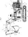
- Fig. 1 is a schematic side view of an exterior configuration of a hydraulic excavator 1 as an example of a work machine of Embodiment 1.
- the hydraulic excavator 1 includes an articulated front work device 2 that holds the target object and turns in the vertical or front-back direction, and a machine main body 3 that includes the front work device 2.
- the machine main body 3 includes a lower traveling body 5 that is driven by a right traveling hydraulic motor 4a and a left traveling hydraulic motor 4b provided on the right and left parts of the lower traveling body 5, and an upper swing body 7 that is attached to an upper part of the lower traveling body 5 via a swinging device and swinged by a swinging hydraulic motor 6 of the swinging device.
- the right traveling hydraulic motor 4a and the left traveling hydraulic motor 4b are also collectively referred to as "traveling hydraulic motors 4a and 4b.”
- the front work device 2 is an articulated work apparatus constituted of a plurality of front members attached to a front of the upper swing body 7.
- the upper swing body 7 on which the front work device 2 is mounted swings.
- the front work device 2 includes a boom 8 vertically turnably connected to the front of the upper swing body 7, an arm 9 vertically turnably connected to a distal part of the boom 8, and a bucket 10 vertically turnably connected to a distal part of the arm 9.
- the boom 8 is connected to the upper swing body 7 by a boom pin 8a and is turned by expansion and contraction of a boom cylinder 11.
- the arm 9 is connected to the distal part of the boom 8 by an arm pin 9a and is turned by expansion and contraction of an arm cylinder 12.
- the bucket 10 is connected to the distal part of the arm 9 by a bucket pin 10a and a bucket link 16, and is turned by expansion and contraction of a bucket cylinder 13.
- a boom angle sensor 14 is attached to the boom pin 8a to detect a turn angle of the boom 8.
- An arm angle sensor 15 is attached to the arm pin 9a to detect a turn angle of the arm 9.
- a bucket angle sensor 17 is attached to the bucket link 16 to detect a turn angle of the bucket 10.
- Each turn angle of the boom 8, the arm 9, and the bucket 10 may be acquired by detecting each angle of the boom 8, the arm 9, and the bucket 10 with respect to a reference plane such as the horizontal plane using an inertial measurement device and converting it to each of the turn angles.
- Each turn angle of the boom 8, the arm 9, and the bucket 10 may be acquired by detecting each stroke of the boom cylinder 11, the arm cylinder 12, and the bucket cylinder 13 with a stroke sensor and converting it to each of the turn angles.
- An inclination angle sensor 18 is attached to the upper swing body 7 to detect an inclination angle of the machine main body 3 with respect to the reference plane such as the horizontal plane.
- a swinging device between the lower traveling body 5 and the upper swing body 7 includes a swing angle sensor 19 to detect a swing angle, which is a relative angle of the upper swing body 7 with respect to the lower traveling body 5.
- An angular speed sensor (not illustrated) is attached to the upper swing body 7 to detect an angular speed of the upper swing body 7.
- the boom angle sensor 14, the arm angle sensor 15, the bucket angle sensor 17, the inclination angle sensor 18, and the swing angle sensor 19 are also collectively referred to as a "posture detection device 53."
- the posture detection device 53 detects the respective turn angles of the front work device 2, the swing angle of the upper swing body 7, and the like.
- a display device 55 constituted of a touch screen or the like that can accept operator input is installed in a cab provided on the upper swing body 7.
- an operating device for operating a plurality of hydraulic actuators 4a, 4b, 6, 11, 12, and 13 is installed in the cab provided on the upper swing body 7.
- the operating devices include a traveling right lever 23a for operating the right traveling hydraulic motor 4a, a traveling left lever 23b for operating the left traveling hydraulic motor 4b, an operation right lever 22a for operating the boom cylinder 11 and the bucket cylinder 13, and an operation left lever 22b for operating the arm cylinder 12 and the swinging hydraulic motor 6.
- the traveling right lever 23a, the traveling left lever 23b, the operation right lever 22a, and the operation left lever 22b are also collectively referred to as "operation levers 22, 23.”
- An external measuring device 70 is also attached to the upper swing body 7 to measure a surrounding environment of a body of the hydraulic excavator 1.
- the external measuring device 70 measures a depth (a distance to an object) of an object present around the hydraulic excavator 1.
- the external measuring device 70 acquires depth information of the object as a measurement result.
- the external measuring device 70 may be, for example, a light detection and ranging (LiDAR) or a stereo camera.
- a plurality of the external measuring device 70 may be installed on the hydraulic excavator 1.
- a positioning device 60 is also attached to the upper swing body 7 to measure a position and an orientation of the hydraulic excavator 1 at a site.
- the positioning device 60 acquires positioning information including the position and the orientation of the hydraulic excavator 1 at the site as the measurement result.
- the positioning device 60 may be, for example, a GNSS receiver, a total station (TS), or other surveying devices.
- the positioning device 60 may be, but is not limited to, for example, a camera fixed at the site.
- the positioning device 60 may measure the position and the orientation of the hydraulic excavator 1 at the site based on the information calculated from the detected image of the hydraulic excavator 1. In this case, at least two of the positioning devices 60 preferred to be provided to accurately measure the orientation of the hydraulic excavator 1.
- a truck information acquisition device 56 is also attached to the upper swing body 7 to acquire truck information, which includes position, posture, and vehicle class information of the dump truck 200, from an external source.
- the vehicle class information includes information on a vehicle type and dimensions of the dump truck 200.
- the truck information acquisition device 56 may be a communication terminal that performs wireless communication with a position and dispatch management system of the dump trucks 200, such as a fleet management system (FMS), for example.
- FMS fleet management system
- the truck information acquisition device 56 can acquire truck information by receiving the truck information of the dump trucks 200 transmitted from the position and dispatch management system of the dump trucks 200.
- the truck information acquisition device 56 may be configured as software implementing functions of the truck information acquisition device 56 and may be embedded in an information processing device 54.
- the truck information acquisition device 56 can acquire information regarding the position adjustment amount of the dump truck 200 based on the adjustment function and the truck information of the dump truck 200 at the same time from the position and dispatch management system.
- a task acquisition device 58 is also attached to the upper swing body 7 to acquire a task indicating the next operation contents (or the work contents) to be performed by the hydraulic excavator 1.
- the task acquisition device 58 may be, for example, a communication terminal that performs wireless communication with a management device that manages the work site.
- the task acquisition device 58 can acquire the tasks by receiving the tasks of the hydraulic excavator 1 transmitted from the management device.
- the task acquisition device 58 may be configured by a communication terminal shared with the truck information acquisition device 56.
- the task acquisition device 58 may be configured as software that implements functions of the task acquisition device 58 and may be embedded in the information processing device 54.
- the task acquisition device 58 may also acquire the task by automatically determining the task from the operation of the operation levers 22, 23 by the operator.
- the task acquisition device 58 may be an input terminal that can be operated by the operator, and may acquire the task by accepting the operator input. The method of acquiring the tasks is not limited in the present embodiment.
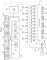
- Fig. 2 is a block diagram illustrating a hydraulic system and a control system mounted on the hydraulic excavator 1 illustrated in Fig. 1 .
- An engine 103 which is a prime mover mounted on the upper swing body 7, drives a hydraulic pump 102 and a pilot pump 104.
- the control device 40 controls a turning movement of the front work device 2, a traveling movement of the lower traveling body 5, and a swinging movement of the upper swing body 7 (that is, the movement of the body of the hydraulic excavator 1 constituted thereof) according to the operation information (operation amount and operation direction) of the operation levers 22, 23 by the operator.
- the control device 40 detects the operation information (operation amount and operation direction) of the operation levers 22, 23 by the operator using sensors 52a to 52f such as rotary encoders or potentiometers, and outputs control commands to solenoid proportional valves 47a to 471 in accordance with the detected operation information.
- the solenoid proportional valves 47a to 471 are installed in a pilot line 100 and are activated when the control commands from the control device 40 is input, and output pilot pressures to a flow control valve 101 to activate the flow control valve 101.
- the flow control valve 101 controls a pressure oil supplied from the hydraulic pump 102 to each of the swinging hydraulic motor 6, the arm cylinder 12, the boom cylinder 11, the bucket cylinder 13, the right traveling hydraulic motor 4a, and the left traveling hydraulic motor 4b according to the pilot pressures from the solenoid proportional valves 47a to 471.
- the solenoid proportional valves 47a, 47b output a pilot pressure to the flow control valve 101 to control the pressure oil supplied to the swinging hydraulic motor 6.
- the solenoid proportional valves 47c, 47d output a pilot pressure to the flow control valve 101 to control the pressure oil supplied to the arm cylinder 12.
- the solenoid proportional valves 47e, 47f output a pilot pressure to the flow control valve 101 to control the pressure oil supplied to the boom cylinder 11.
- the solenoid proportional valves 47g, 47h output a pilot pressure to the flow control valve 101 to control the pressure oil supplied to the bucket cylinder 13.
- the solenoid proportional valves 47i, 47j output a pilot pressure to the flow control valve 101 to control the pressure oil supplied to the traveling right traveling hydraulic motor 4a.
- the solenoid proportional valves 47k, 471 output a pilot pressure to the flow control valve 101 to control the pressure oil supplied to the traveling left traveling hydraulic motor 4b.
- the boom cylinder 11, the arm cylinder 12, and the bucket cylinder 13 expand and contract by the supplied pressure oils to rotate the boom 8, the arm 9, and the bucket 10, respectively. This changes the position and the posture of the bucket 10.
- the swinging hydraulic motor 6 is rotated by the supplied pressure oil to swing the upper swing body 7.
- the right traveling hydraulic motor 4a and the left traveling hydraulic motor 4b are rotate by the supplied pressure oils for causing the lower traveling body 5 to travel.
- the control device 40 can automatically (semi-automatically or fully automatically) control the movements of the body of the hydraulic excavator 1 (the turning movement of the front work device 2, the traveling movement of the lower traveling body 5, and the swinging movement of the upper swing body 7) based on the recognition results of the information processing device 54.
- the information processing device 54 recognizes the dump truck 200 present around the hydraulic excavator 1 based on the measurement result of the external measuring device 70.
- the information processing device 54 is constituted of a computer including a Central Processing Unit (CPU) 73, a Random Access Memory (RAM) 72, a Read Only Memory (ROM) 71, and an external I/F (Interface) 74, and the like connected to each other by a bus 75.
- the control device 40, the display device 55, the external measuring device 70, the positioning device 60, the posture detection device 53, the task acquisition device 58, the truck information acquisition device 56, and a storage device 57 are connected to an external I/F 74.
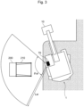
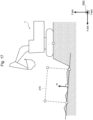
- Fig. 3 is a diagram illustrating an example of an operation of the hydraulic excavator 1 illustrated in Fig. 2 .
- the dump truck 200 stops at a predetermined position where the hydraulic excavator 1 can load the target object.
- the task acquisition device 58 of the hydraulic excavator 1 acquires a loading task for the next task, which is to load the excavated target objects such as earth and sand onto the dump truck 200.
- the external measuring device 70 of the hydraulic excavator 1 measures a vessel of the dump truck 200.
- the information processing device 54 of the hydraulic excavator 1 calculates a recognition area and an estimated area described below for a presence area 210 of the dump truck 200.
- the information processing device 54 of the hydraulic excavator 1 calculates the position of the bucket 10 when loading the target object from the bucket 10 onto the vessel of the dump truck 200 (hereinafter also referred to as "loading position"). Based on the calculated recognition area and estimated area of the dump truck 200 and the loading position, the control device 40 of the hydraulic excavator 1 outputs the control commands to move the bucket 10 to the loading position such that the front work device 2 does not collide with the dump truck 200. This allows the hydraulic excavator 1 to automatically control the loading work appropriately without colliding with the dump truck 200.
- the dump truck 200 is assumed to be parked at a predetermined position where the hydraulic excavator 1 can load the target objects.
- the dump truck 200 of the present embodiment has a position of the dump truck 200 at the work site controlled by the position and dispatch management system of the dump trucks 200, such as FMS.
- the dump truck 200 is controlled until the dump truck 200 stops at a predetermined position.
- the dump truck 200 may be stopped at a predetermined position by the operator of the dump truck 200.
- the operator of the hydraulic excavator 1 may visually confirm that the dump truck 200 has stopped at the predetermined position, or the information processing device 54 may recognize that the dump truck 200 has stopped at the predetermined position based on the measurement result of the external measuring device 70.
- the external measuring device 70 of Fig. 3 is mounted to face the left side of the hydraulic excavator 1, but may be mounted to face the front of the hydraulic excavator 1. Furthermore, the hydraulic excavator 1 may further include the external measuring device 70 mounted to face the right side or rear of the hydraulic excavator 1.
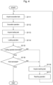
- Fig. 4 is a flowchart illustrating an example of the operation of the hydraulic excavator 1 illustrated in Fig. 2 .
- Step S111 the task acquisition device 58 of the hydraulic excavator 1 acquires an excavation task to excavate the ground to be excavated.
- Step S112 the control device 40 of the hydraulic excavator 1 controls the turning movement of the front work device 2 to cause the hydraulic excavator 1 to perform the excavation operation according to the acquired excavation task.
- Step S113 the task acquisition device 58 of the hydraulic excavator 1 acquires a loading task for loading the excavated target object such as earth and sand onto the dump truck 200.
- Step S114 the control device 40 of the hydraulic excavator 1 controls the turning movement of the front work device 2 and the swinging movement of the upper swing body 7 to cause the hydraulic excavator 1 to perform the loading operation according to the acquired loading task.
- Step S115 the control device 40 of the hydraulic excavator 1 determines whether or not to terminate the loading onto the dump truck 200.
- the operator of the hydraulic excavator 1 may notify the control device 40 that the loading onto the dump truck 200 is terminated by operating the certain operation levers 22, 23 or by entering information on the display device 55, after visual confirmation.
- the control device 40 may determine to terminate the loading onto the dump truck 200 by the notification of these operations from the operator.
- the control device 40 may determine to terminate the loading onto the dump truck 200 based on the determination result of a load determination device that measures the load of the target object loaded onto the dump truck 200 to determine that the load is appropriate.
- the control device 40 proceeds to Step S118.
- the control device 40 proceeds to Step S116.
- Step S116 the task acquisition device 58 of the hydraulic excavator 1 acquires a reaching task for moving the front work device 2 to the next ground to be excavated.
- Step S117 the control device 40 of the hydraulic excavator 1 controls the turning movement of the front work device 2, the traveling movement of the lower traveling body 5, and the swinging movement of the upper swing body 7 to cause the hydraulic excavator 1 to perform a reaching operation according to the acquired reaching task. Thereafter, the control device 40 proceeds to Step S111.
- Step S118 the control device 40 of the hydraulic excavator 1 determines whether or not to terminate the work.
- the control device 40 may determine that the work is terminated when the task acquisition device 58 acquires a work end notification. Alternatively, the control device 40 may determine that the work is terminated when the operator or a manager stops the engine 103 of the hydraulic excavator 1.
- the control device 40 interrupts the operation of the hydraulic excavator 1 to terminate the work.
- the control device 40 proceeds to Step S116.
- the hydraulic excavator 1 continues the reaching operation, the excavation operation, and the loading operation.
- the tasks and the operations of the hydraulic excavator 1 are not limited to those illustrated in Fig. 4 , and may include tasks and operations not illustrated in Fig. 4 , such as moving or leveling, for example.
- the information processing device 54 recognizes the dump truck 200 based on the measurement result of the external measuring device 70 each time the task acquisition device 58 acquires each task. The information processing device 54 then verifies whether the recognition result of the dump truck 200 is not valid to the extent that it cannot be corrected, or whether the recognition result of the dump truck 200 is valid to the extent that it can be corrected (hereinafter referred to as "verifying validity"). When the recognition result of the dump truck 200 is valid, the information processing device 54 corrects the recognition result.
- a process of verifying the validity of the recognition result of the dump truck 200 and correcting the recognition result is also referred to as the "recognition result verification process.”
- the functions of the information processing device 54 that performs the recognition result verification process are described below.
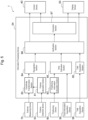
- Fig. 5 is a block diagram illustrating a functional configuration of the information processing device 54 illustrated in Fig. 2 .
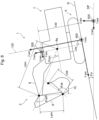
- Fig. 6 is a view illustrating respective coordinate systems 300 to 500 set up on the hydraulic excavator 1, viewed from side.
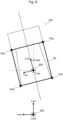
- Fig. 7 is a view illustrating the respective coordinate systems 300 to 500 illustrated in Fig. 6 , viewed from above.
- the information processing device 54 includes a posture calculation section 81, a coordinate transformation section 82, a positioning information calculation section 83, a task acquisition section 80, a recognition section 84, an area estimation section 85, a verification section 86, and a correction section 87.
- the body coordinate system 400 illustrated in Figs. 6 and 7 is preset as a reference coordinate system for identifying the positions and the postures of components of the hydraulic excavator 1.
- the body coordinate system 400 of the hydraulic excavator 1 in the present embodiment is defined as a right-hand coordinate system with the origin at the point where the lower traveling body 5 contact the ground G in a swing center line 120 of the upper swing body 7.
- the body coordinate system 400 of the hydraulic excavator 1 is defined with a forward direction of the lower traveling body 5 as a positive direction of the X-axis.
- the body coordinate system 400 of the hydraulic excavator 1 is defined with a direction in which the swing center line 120 extends upward as a positive direction of the Z-axis.
- the body coordinate system 400 of the hydraulic excavator 1 is defined as orthogonal to each of the X-and Z-axes, with a left direction as a positive direction of the Y-axis.
- the swing angle ⁇ sw of the upper swing body 7 is defined as 0 degrees when the front work device 2 is parallel to the X-axis.
- the present embodiment also defines a sensor coordinate system 300, as illustrated in Figs. 6 and 7 , as the reference coordinate system for the external measuring device 70.
- the present embodiment defines the site coordinate system 500, as illustrated in Figs. 6 and 7 , as the reference coordinate system for the site.
- the posture calculation section 81 calculates the postures and the like of the components of the hydraulic excavator 1 in the body coordinate system 400 of the hydraulic excavator 1 from detection signals of the posture detection device 53. Specifically, the posture calculation section 81 calculates a turn angle ⁇ bm of the boom 8 with respect to the X-axis from the detection signal of the turn angle of the boom 8 output from the boom angle sensor 14. The posture calculation section 81 calculates the turn angle ⁇ am of the arm 9 with respect to the boom 8 from the detection signal of the turn angle of the arm 9 output from the arm angle sensor 15. The posture calculation section 81 calculates the turn angle ⁇ bk of the bucket 10 with respect to the arm 9 from the detection signal of the turn angle of the bucket 10 output from the bucket angle sensor 17.
- the posture calculation section 81 calculates the swing angle ⁇ sw of the upper swing body 7 with respect to the X-axis (the lower traveling body 5) from the detection signal of the swing angle of the upper swing body 7 output from the swing angle sensor 19. Furthermore, the posture calculation section 81 calculates a turning angular velocity ⁇ sw of the upper swing body 7 from the swing angle ⁇ sw of the upper swing body 7.
- the posture calculation section 81 calculates the inclination angle of the machine main body 3 (the lower traveling body 5) with respect to a reference plane DP from the detection signal of the inclination angle of the machine main body 3 output from the inclination angle sensor 18.
- the reference plane DP is, for example, a horizontal plane orthogonal to the direction of gravity.
- the inclination angle includes a rotation angle ⁇ p about the Y-axis and a rotation angle ⁇ r about the X-axis.
- the coordinate transformation section 82 transforms the coordinate system expressing the depth information acquired by the external measuring device 70 from the sensor coordinate system 300 to the body coordinate system 400 of the hydraulic excavator 1 using the posture information of the hydraulic excavator 1 output from the posture calculation section 81.
- the depth information acquired by the external measuring device 70 is given as a set of three-dimensional point data (that is, point cloud data) expressed in the sensor coordinate system 300.
- Rsv is a rotation matrix from the sensor coordinate system 300 to the body coordinate system 400.
- ⁇ s, ⁇ s, and ⁇ s are the angles formed by respective axes of the external measuring device 70 (respective axes of the sensor coordinate system 300) in the body coordinate system 400.
- the angles formed by these angles can be measured in advance by measuring the attitude of the external measuring device 70 in the body coordinate system 400 and storing them in the storage device 57 in advance.
- a posture measuring sensor may be attached to the external measuring device 70 or the like, and the angle detected by the posture measuring sensor may be used to calculate a coordinate transformation matrix.
- ⁇ sw is the swing angle of the upper swing body 7 and is output from the posture calculation section 81.
- Tsv is a translational vector from the origin of the body coordinate system 400 to the origin of the sensor coordinate system 300.
- Lsx, Lsy, and Lsz are equal to the origin coordinates of the sensor coordinate system 300 as viewed from the body coordinate system 400.
- a mounting position of the external measuring device 70 is often fixed on the hydraulic excavator 1. Therefore, in such cases, the mounting position of the external measuring device 70 on the hydraulic excavator 1 can be measured in advance and stored in the storage device 57 in advance.
- the positioning information calculation section 83 calculates the position of the origin of the body coordinate system 400 in the site coordinate system 500 of the hydraulic excavator 1 and an orientation ⁇ dir in the site coordinate system 500 of the front work device 2 from the positioning information acquired by the positioning device 60.
- the task acquisition section 80 acquires the next task to be performed by the hydraulic excavator 1 from the task acquisition device 58.
- the tasks to be performed by the hydraulic excavator 1 include the excavation task, the loading task, and the reaching task.
- the excavation task is a task that specifies the excavation operation until the hydraulic excavator 1 excavates the ground to be excavated and holds the target object such as earth and sand in the bucket 10.
- the loading task is a task that specifies the loading operation from a state in which the hydraulic excavator 1 terminates the excavation operation until the bucket 10 is moved to above the vessel of the dump truck 200 and the target object is released from the bucket 10 onto the vessel.
- the reaching task is a task that specifies the reaching operation in which the hydraulic excavator 1 moves the bucket 10 from the state in which the loading operation is terminated to the position in which the ground to be excavated next is located.
- the tasks performed by the hydraulic excavator 1 are not limited to these tasks.
- a leveling task that specifies a leveling operation in which the hydraulic excavator 1 levels the surrounding ground until the dump truck 200 stops at a predetermined position at the site, and/or a leveling task that specifies a moving operation in which the hydraulic excavator 1 changes the ground to be excavated may be included.
- the recognition section 84 recognizes the dump truck 200 from the measurement results of the external measuring device 70. Specifically, the recognition section 84 recognizes the position, the posture, and the shape of the dump truck 200 using the point cloud data, which are acquired as the measurement result of the external measuring device 70 and converted to the body coordinate system 400 by the coordinate transformation section 82. The recognition section 84 then calculates a recognition area, which is an area where the recognized dump truck 200 is present. In other words, the recognition area is the recognition result of the recognition section 84 for the presence area 210 of the dump truck 200.
- a method of calculating the recognition area of the dump truck 200 by the recognition section 84 is, for example, to maintain a 3-D mesh model of the dump truck 200 measured in advance in the storage device 57. Then, the position, the posture, and the shape are collated between the point cloud data converted to the body coordinate system 400 acquired from the coordinate transformation section 82 and the 3D mesh model. As a result, the recognition section 84 can calculate the position, the posture, and the shape of the target dump truck 200, and thus can calculate the recognition area of the dump truck 200.
- the method of calculating the recognition area of the dump truck 200 is not limited thereto, and may be, for example, a method of calculating the recognition area of the dump truck 200 by a process of extracting a specific plane of the dump truck 200 from the point cloud data acquired from the external measuring device 70.
- a neural network that calculates the recognition area of the dump truck 200 from the point cloud data including the dump truck 200 may be constructed in advance, and the features of the dump truck 200 to be recognized may be calculated using a discriminator that has been machine-learned.
- the position, the posture, and the presence area 210 of the dump truck 200 are defined as follows.
- Fig. 8 is a view of a body coordinate system 600 of the dump truck 200, viewed from side.
- Fig. 9 is a view illustrating the body coordinate system 600 illustrated in Fig. 8 , viewed from above.
- the body coordinate system 600 of the dump truck 200 has the center of the rear axle of the dump truck 200 as the origin, and the X-axis is a direction from the rear wheels to the front wheels, the Y-axis is a direction where the rear axle extends, and the Z-axis is a direction of the height of the dump truck 200.
- the position of the dump truck 200 designates the origin Pd (Xd, Yd, Zd) of the body coordinate system 600.
- the posture of the dump truck 200 refers to the angle ⁇ d ( ⁇ roll, ⁇ pitch, ⁇ yaw) formed by the respective axes of the site coordinate system 500 and the respective axes of the body coordinate system 600 of the dump truck 200.
- the presence area 210 of the dump truck 200 refers to a rectangular area Sd (Pd1 to Pd4) with the points Pd1 to Pd4 at the four corners of the vessel of the dump truck 200 as vertices.
- the presence area 210 of the dump truck 200 is not limited thereto, and may be, for example, a hexahedron (for example, a rectangle or cube) that encompasses the entire dump truck 200.
- the recognition area of the dump truck 200 which is the recognition result of the recognition section 84 for the presence area 210 of the dump truck 200, is Sdr (Pdr1 to Pdr4).
- the area estimation section 85 calculates an estimated area, which is an area where the dump truck 200 is estimated to be present, from the position and the vehicle class information (truck information) of the dump truck 200 acquired by the truck information acquisition device 56.
- the estimated area is an estimation result of the area estimation section 85 for the presence area 210 of the dump truck 200.
- the estimated area is calculated for comparison with the recognition area of the dump truck 200 calculated by the recognition section 84 in order to verify validity of the recognition result of the dump truck 200.
- the method of calculating the estimated area of the dump truck 200 by the area estimation section 85 stores, for example, a method of calculating the estimated area of the dump truck 200 from the truck information in the storage device 57 in advance for each vehicle type. Then, using the truck information acquired by the truck information acquisition device 56 and the calculation method corresponding to the truck information, the estimated area in the site coordinate system 500 of the target dump truck 200 is calculated and converted to the body coordinate system 400 of the hydraulic excavator 1. This allows the area estimation section 85 to calculate the estimated area of the dump truck 200 that can be compared with the recognition area of the dump truck 200 calculated by the recognition section 84. In the present embodiment, assume that the estimated area of the dump truck 200, which is the estimation result of the area estimation section 85 for the presence area 210 of the dump truck 200, is Sde (Pde1 to Pde4).
- the transformation from the site coordinate system 500 to the body coordinate system 400 of the hydraulic excavator 1 can be performed using the following formulae.
- the following Formulae (4) to (6) are used to convert from the point data Pv (Xv, Yv, Zv) in the body coordinate system 400 of the hydraulic excavator 1 to the point data Pg (Xg, Yg, Zg) in the site coordinate system 500.
- P v R vg ⁇ 1 ⁇ P g ⁇ T vg ⁇ T sv
- Rvg is a rotation matrix from the body coordinate system 400 to the site coordinate system 500.
- ⁇ r, ⁇ p, and ⁇ y are the angles formed by respective axes of the body coordinate system 400 in the site coordinate system 500. These angles can be calculated using the values calculated by the posture calculation section 81, the swing angle, the inclination angle of the machine main body 3, and the orientation calculated by the positioning information calculation section 83.
- Tvg is a translational vector from the origin of the site coordinate system 500 to the origin of the body coordinate system 400.
- X0, y0, z0 are equal to the origin coordinates of the body coordinate system 400 as viewed from the site coordinate system 500.
- a calculation result of the positioning information calculation section 83 can be used.
- the area estimation section 85 can adjust the position of the dump truck 200 included in the truck information using the position adjustment amount of the dump truck 200 that was simultaneously acquired with the truck information by the truck information acquisition device 56. The area estimation section 85 can then calculate the estimated area of the dump truck 200 from the adjusted position of the dump truck 200.
- the verification section 86 verifies the validity of the recognition result of the dump truck 200 based on the recognition area calculated by the recognition section 84 and the estimated area calculated by the area estimation section 85. Specifically, the verification section 86 calculates a confidence of the recognition result of the dump truck 200 by comparing the recognition area with the estimated area, and verifies the validity of the recognition result of the dump truck 200 according to the calculated confidence. In detail, the verification section 86 calculates an overlap degree, which indicates a degree of an overlap between the recognition area and the estimated area, as the confidence of the recognition result of the dump truck 200. When the calculated overlap degree is higher than a threshold, the verification section 86 determines that the recognition result of the dump truck 200 is valid (correctable). In this case, the verification section 86 can change the threshold of the overlap degree, which is a criterion for determining the validity of the recognition result, according to the task acquired by the task acquisition section 80.
- the correction section 87 corrects the recognition area calculated by the recognition section 84 based on the estimated area calculated by the area estimation section 85. Specifically, the correction section 87 compares the recognition area calculated by the recognition section 84 with the estimated area calculated by the area estimation section 85 and corrects the recognition area calculated by the recognition section 84. Accordingly, the correction section 87 corrects the recognition result of the dump truck 200. At this time, the correction section 87 can change the correction method of the recognition area (the recognition result) calculated by the recognition section 84 according to the task acquired by the task acquisition section 80.
- the information processing device 54 uses the verification section 86 and the correction section 87 to verify the validity of the recognition result of the dump truck 200, and performs the recognition result verification process to correct the recognition result.
- the recognition result verification process is described in detail below.
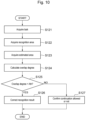
- Fig. 10 is a flowchart illustrating an example of the recognition result verification process.
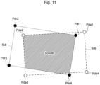
- Fig. 11 is a view illustrating the overlap degree of the recognition area and the estimated area.
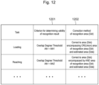
- Fig. 12 is a view illustrating a table that defines criteria for determining the validities of the recognition results and the methods of correction of the recognition areas for the respective tasks of the hydraulic excavator 1.
- Fig. 13 is a view illustrating the method of correcting the recognition area when acquiring the loading task.
- Fig. 14 is illustrating a method of correcting the recognition area when acquiring the reaching task.
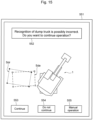
- Fig. 15 is a view illustrating an example of the display device 55 when the confidence of the recognition result is equal to or lower than the threshold.
- Step S121 the verification section 86 of the information processing device 54 acquires the task acquired by the task acquisition section 80.
- Step S122 the verification section 86 of the information processing device 54 acquires the recognition area calculated by the recognition section 84.
- Step S123 the verification section 86 of the information processing device 54 acquires the estimated area calculated by the area estimation section 85.
- Step S124 the verification section 86 of the information processing device 54 calculates the confidence of the recognition result of the dump truck 200.
- the verification section 86 calculates the overlap degree Acover, which indicates the overlap between the recognition area calculated by the recognition section 84 and the estimated area calculated by the area estimation section 85, as the confidence of the recognition result of the dump truck 200.
- Sde indicates an area of the estimated area calculated by the area estimation section 85.
- Scover indicates an area of the area where the recognition area (Sdr) calculated by the recognition section 84 and the estimated area (Sde) calculated by the area estimation section 85 overlap. Scover can be attributed, for example, to a problem of finding an area of an intersection of two convex polygons, for example, and can be solved as a numerical calculation problem.
- Step S125 the verification section 86 of the information processing device 54 determines whether the calculated overlap degree Acover is higher than a threshold Ath. Accordingly, the verification section 86 verifies the validity of the recognition result of the dump truck 200. When the calculated overlap degree Acover is higher than the threshold Ath, the verification section 86 determines that the recognition result of the dump truck 200 is valid (correctable) and proceeds to Step S126. When the calculated overlap degree Acover is equal to or lower than the threshold Ath, the verification section 86 determines that the recognition result of the dump truck 200 is not valid (not correctable) and proceeds to Step S127.
- the verification section 86 can change the threshold Ath of the overlap degree Acover, which is the criterion for determining the validity of the recognition result, according to the task acquired by the task acquisition section 80, as illustrated in Fig. 12 .
- the table illustrated in Fig. 12 is stored in the storage device 57 in advance. As illustrated in Column 1201 of the table illustrated in Fig. 12 , when the task acquired by the task acquisition section 80 is the loading task, the verification section 86 sets Ath1 as the threshold Ath. When the task acquired by the task acquisition section 80 is the reaching task, the verification section 86 sets Ath2 as the threshold Ath.
- Ath1 and Ath2 are preferred to be determined with the calculation accuracy of the respective areas of the area estimation section 85 and the recognition section 84 during the functional verification conducted in advance, the presence or absence of the target object in the bucket 10 when the task is acquired, the distance between the front work device 2 and the dump truck 200, and other factors taken into account.
- the hydraulic excavator 1 starts in a state where the target object is in the bucket 10 and the distance between the front work device 2 and the dump truck 200 is large.
- the damage caused when the front work device 2 collides with the dump truck 200 is considered to be greater during the loading operation than during the reaching operation. Therefore, the threshold Ath1 set when the loading task is acquired preferred to be the same value or higher than the threshold Ath2 set when the reaching task is acquired.
- Step S126 the correction section 87 of the information processing device 54 corrects the recognition result of the dump truck 200. Specifically, the correction section 87 corrects the recognition area calculated by the recognition section 84. The correction section 87 then outputs the determination result that the recognition result of the dump truck 200 is valid (correctable), the confidence (the overlap degree) of the recognition result, and the recognition area after the correction, to the control device 40. Furthermore, the correction section 87 may display the information output to the control device 40 on the display device 55 to notify the operator, or transmit the information to the management device that manages the work site to notify the manager. The information processing device 54 then terminates the recognition result verification process illustrated in Fig. 10 .
- the correction section 87 can change the correction method of the recognition area calculated by the recognition section 84 according to the task acquired by the task acquisition section 80, as illustrated in Fig. 12 .
- the correction section 87 corrects the recognition area calculated by the recognition section 84 to be an area (Sdc) that encompasses the recognition area (Sdr) and the estimated area (Sde) as illustrated in Fig. 13 .
- the area encompassing the recognition area (Sdr) and the estimated area (Sde) is the area (Sdc) that encompasses an OR(Union) area occupied by the recognition area (Sdr) or the estimated area (Sde).
- the correction section 87 corrects the recognition area (Sdr) calculated by the recognition section 84 to a rectangular area (Sdc) that encompasses the recognition area (Sdr) and the estimated area (Sde) and has the smallest area.
- the hydraulic excavator 1 moves the bucket 10 from the ground outside the dump truck 200 toward above the vessel inside of the dump truck 200 to the loading position. Therefore, when the recognition area calculated by the recognition section 84 is corrected to an area that encompasses the recognition area and the estimated area, the risk of the front work device 2 moving from the outside to the inside of the dump truck 200 colliding with the dump truck 200 during the loading operation is reduced. Therefore, when the task acquired by the task acquisition section 80 is the loading task, the correction section 87 corrects the recognition area calculated by the recognition section 84 to be the area that encompasses the recognition area and the estimated area.
- the correction section 87 can calculate the position in the height direction (the Z-axis direction) of the recognition area after the correction as follows. That is, the correction section 87 can use the maximum value of the Z-axis component of the coordinates of respective vertices of the recognition area and the estimated area as the position of the recognition area in the height direction after the correction, in order to avoid the collision between the front work device 2 and the dump truck 200.
- the correction section 87 can calculate the orientation vdc of the recognition area after the correction, using the orientation vector vdr of the recognition area and the orientation vector vde of the estimated area, for example, from Formulae (8) to (9) below.
- v dc v dr + G k v de ⁇ v dr
- G k ⁇ x de ⁇ x dr + ⁇ x de 0 0 0 ⁇ y de ⁇ y dr + ⁇ y de 0 0 0 ⁇ z de ⁇ z dr + ⁇ z de
- ⁇ dr ( ⁇ xdr, ⁇ ydr, ⁇ zdr) used in the calculation of the gain Gk in the above-described Formula (9) is information on the calculation accuracy of the recognition area in the recognition section 84.
- ⁇ dr for example, the measurement accuracy of the external measuring device 70 and the calculation accuracy of the recognition section 84, which are measured in advance can be used.
- the discriminator using the machine learning is used in the recognition algorithm of the recognition section 84, the information on the recognition confidence output by the discriminator may be used as ⁇ dr.
- ⁇ de ( ⁇ xde, ⁇ yde, ⁇ zde) used in the calculation of the gain Gk in the above-described Formula (9) is information on the calculation accuracy of the estimated area in the area estimation section 85.
- the position adjustment amount of the dump truck 200 that can be acquired simultaneously with the truck information by the truck information acquisition device 56 can be used.
- the correction section 87 can correct the recognition area calculated by the recognition section 84 using the position adjustment amount of the dump truck 200 acquired by the truck information acquisition device 56.
- the truck information acquisition device 56 is unable to acquire the position adjustment amount, as ⁇ de, the result of a prior investigation of the error of the positioning information acquired by the positioning device 60 at the site of the hydraulic excavator 1 can be used.
- the gain Gk is given by the above-described Formula (9) including ⁇ de.
- the correction section 87 can calculate the loading position of the bucket 10 based on the position adjustment amount of the dump truck 200 acquired by the truck information acquisition device 56, the recognition area, and the estimated area. The correction section 87 outputs the calculated loading position of the bucket 10 to the control device 40.
- the correction section 87 corrects the recognition area (Sdr) calculated by the recognition section 84 such that the recognition area (Sdr) becomes the area (Sdc) encompassed by the overlapping area of the recognition area (Sdr) and the estimated area (Sde) as illustrated in Fig. 14 .
- the area (Sdc) encompassed by the area where the recognition area (Sdr) and the estimated area (Sde) overlap is the area (Sdc) encompassed by an AND area occupied by both the recognition area (Sdr) and the estimated area (Sde).
- the correction section 87 corrects the recognition area (Sdr) calculated by the recognition section 84 to the rectangular area (Sdc) that encompasses the recognition area (Sdr) and the estimated area (Sde) and has the largest area.
- the hydraulic excavator 1 moves the bucket 10 from the loading position above the vessel inside the dump truck 200 to the ground outside the dump truck 200. Therefore, when the recognition area calculated by the recognition section 84 is corrected to the area encompassed by the overlapping area of the recognition area and the estimated area, the risk of the front work device 2 moving from the inside to the outside of the dump truck 200 colliding with the dump truck 200 during the reaching operation is reduced. Therefore, when the task acquired by the task acquisition section 80 is the reaching task, the correction section 87 corrects the recognition area calculated by the recognition section 84 such that the recognition area becomes the area encompassed by the area overlapping the recognition area and the estimated area.
- the correction section 87 can use the maximum value of the Z-axis component of the coordinates of respective vertices of the recognition area and the estimated area as the position of the recognition area in the height direction (Z-axis direction) after the correction. Similarly to when the loading task is acquired, the correction section 87 can calculate the orientation of the recognition area after the correction from the above-described Formulae (8) to (9).
- Step S127 the verification section 86 of the information processing device 54 outputs the determination result that the recognition result of the dump truck 200 is not valid (not correctable), the confidence (the overlap degree) of the recognition result, the recognition area, and the estimated area, to the control device 40. Furthermore, the verification section 86 notifies the operator by displaying the information output to the control device 40 on the display device 55, and/or notifies the manager by transmitting the information to the management device that manages the work site. At this time, the verification section 86 confirms with the operator or a user such as the manage whether or not the hydraulic excavator 1 is allowed to be continued to operate.
- the verification section 86 displays a screen 551 on the display device 55 to notify the user of the determination result that the recognition result of the dump truck 200 is not valid (not correctable) and to confirm with the user whether the operation of the hydraulic excavator 1 is allowed to be continued.
- the screen 551 includes a message 552 to notify the user of the determination result that the recognition result of the dump truck 200 is not valid (not correctable) and to confirm with the user whether the operation of the hydraulic excavator 1 is allowed to be continued.
- the screen 551 includes a button 553 for the user to input the confirmation result that the operation of the hydraulic excavator 1 is to be continued.
- the screen 551 includes a button 554 for the user to input the confirmation result that the operation of the hydraulic excavator 1 is not to be continued.
- the screen 551 includes a button 555 for the user to input that the hydraulic excavator 1 is to be switched from the automatic control to the manual operation by the operator.
- the screen 551 also notifies the user of the positional relationship between the dump truck 200 and the hydraulic excavator 1 by indicating the calculation results of the recognition area (Sdr) and the estimated area (Sde) of the dump truck 200.
- the verification section 86 When the verification section 86 receives the confirmation result from the user as to whether or not the continuation is allowed, it outputs the confirmation result to the control device 40. The information processing device 54 then terminates the recognition result verification process illustrated in Fig. 10 .
- the control device 40 controls the movements of the body of the hydraulic excavator 1 (for example, the turning movement of the front work device 2, the traveling movement of the lower traveling body 5, and the swinging movement of the upper swing body 7) based on the result of the validation of the recognition result of the dump truck 200 by the information processing device 54.
- the control device 40 controls the operation of the hydraulic excavator 1 based on the task acquired by the task acquisition device 58 and the corrected recognition area output from the information processing device 54. Specifically, when the loading task is acquired, the control device 40 controls the loading operation of the hydraulic excavator 1 such that the front work device 2 moves on a trajectory where it does not collide with the dump truck 200 before the bucket 10 reaches the loading position from the ground. When the reaching task is acquired, the control device 40 controls the reaching operation of the hydraulic excavator 1 such that the front work device 2 moves on a trajectory where it does not collide with the dump truck 200 before the bucket 10 reaches the ground to be excavated next from the loading position.
- control device 40 controls the operation of the hydraulic excavator 1 upon the confirmation result output from the information processing device 54 as to whether the operation of the hydraulic excavator 1 is allowed to be continued.
- the hydraulic excavator 1 of Embodiment 1 is the work machine that loads the target object onto the dump truck 200.
- the hydraulic excavator 1 includes the external measuring device 70 that measures the surrounding environment of the body of the hydraulic excavator 1.
- the hydraulic excavator 1 includes the information processing device 54 that recognizes the dump truck 200 present around the body of the hydraulic excavator 1 based on the measurement result of the external measuring device 70.
- the hydraulic excavator 1 includes the control device 40 that controls the operation of the body of the hydraulic excavator 1 based on the recognition result of the information processing device 54.
- the hydraulic excavator 1 includes the truck information acquisition device 56 that acquires the position and the vehicle class information of the dump truck 200 from the external source.
- the information processing device 54 corrects the recognition result of the dump truck 200 based on the position and the vehicle class information of the dump truck 200 acquired by the truck information acquisition device 56.
- the control device 40 controls the operation of the body of the hydraulic excavator 1 based on the corrected recognition result of the dump truck 200.
- the hydraulic excavator 1 of Embodiment 1 can control the loading operation and the like for the dump truck 200 using the accurate recognition result of the dump truck 200 in various situations.
- the hydraulic excavator 1 of Embodiment 1 can verify the validity of the recognition result of the dump truck 200 based on information from a third party acquired by the truck information acquisition device 56, and can correct the recognition result. Then, the hydraulic excavator 1 of Embodiment 1 can appropriately control the loading operation and the like based on the corrected recognition result. In other words, the hydraulic excavator 1 of Embodiment 1 can control the movement of the body of the hydraulic excavator 1 based on the accurate recognition result of the position, the posture, and the like of the dump truck 200. Therefore, the hydraulic excavator 1 of Embodiment 1 can reduce the risk of the collision with the dump truck 200, and control the loading operation and the reaching operation, thereby improving the safety and productivity of the loading work. Thus, according to Embodiment 1, it is possible to provide the hydraulic excavator 1 that can appropriately control the loading work onto the dump truck 200 by accurately recognizing the position and the posture of the dump truck 200 in various situations.
- the information processing device 54 includes the recognition section 84 that recognizes the dump truck 200 from the measurement result of the external measuring device 70 and calculates the recognition area, which is an area in which the recognized dump truck 200 is present.
- the information processing device 54 includes the area estimation section 85 that calculates the estimated area, which is an area where the dump truck 200 is estimated to be present, based on the position and the vehicle class information of the dump truck 200 acquired by the truck information acquisition device 56.
- the information processing device 54 includes the correction section 87 that corrects the recognition area based on the estimated area.
- Embodiment 1 This allows the hydraulic excavator 1 of Embodiment 1 to correct the recognition result based on a relatively simple indicator, which is the presence area of the dump truck 200. Therefore, the hydraulic excavator 1 of Embodiment 1 can accurately and easily recognize the position and the posture of the dump truck 200. The hydraulic excavator 1 of Embodiment 1 can further improve the safety and productivity of the loading work. Thus, according to Embodiment 1, it is possible to easily provide the hydraulic excavator 1 that can appropriately control the loading work onto the dump truck 200 by accurately recognizing the position and the posture of the dump truck 200 in various situations.
- the information processing device 54 calculates the confidence of the recognition result of the dump truck 200 by comparing the recognition area with the estimated area.
- the correction section 87 corrects the recognition area according to the calculated confidence.
- the hydraulic excavator 1 of Embodiment 1 can quantitatively verify the validity of the recognition result of the dump truck 200, and can accurately and precisely correct the recognition area.
- the hydraulic excavator 1 of Embodiment 1 can further improve the safety and productivity of the loading work.
- the information processing device 54 calculates the overlap degree, which indicates the degree of overlap between the recognition area and the estimated area, as the confidence of the recognition result.
- the correction section 87 corrects the recognition area according to the calculated overlap degree.
- the hydraulic excavator 1 of Embodiment 1 can calculate the confidence of the recognition result with a clear standard, and the recognition area can be corrected more accurately and precisely.
- the hydraulic excavator 1 of Embodiment 1 can further improve the safety and productivity of the loading work.
- the truck information acquisition device 56 further acquires information on the position adjustment amount of the dump truck 200.
- the area estimation section 85 calculates the estimated area using the position adjustment amount acquired by the truck information acquisition device 56.
- the hydraulic excavator 1 of Embodiment 1 can calculate the estimated area using values that are more realistic than the error in the positional information of the dump truck 200 acquired through prior verification and the like. Therefore, the hydraulic excavator 1 of Embodiment 1 can further accurately correct the recognition area. The hydraulic excavator 1 of Embodiment 1 can further improve the safety and productivity of the loading work. Thus, according to Embodiment 1, the hydraulic excavator 1 can further accurately recognize the position and the posture of the dump truck 200 in various situations, thereby enabling further appropriate control of the loading work onto the dump truck 200.
- the information processing device 54 further includes the task acquisition section 80 that acquires the next task to be performed by the hydraulic excavator 1.
- the correction section 87 changes the correction method of the recognition area according to the acquired task.
- the hydraulic excavator 1 of Embodiment 1 can correct it to the optimal recognition area for each of the acquired tasks, allowing the hydraulic excavator 1 to perform the optimal operation for each of the acquired tasks.
- the hydraulic excavator 1 of Embodiment 1 can further improve the safety and productivity of loading works.
- correction section 87 corrects the recognition area to be an area that encompasses the recognition area and the estimated area when the loading task for loading the target object onto the dump truck 200 is acquired.
- Embodiment 1 This allows the hydraulic excavator 1 of Embodiment 1 to further reduce the risk of the front work device 2, which moves from the outside to the inside of the dump truck 200 during the loading operation, colliding with the dump truck 200.
- the hydraulic excavator 1 of Embodiment 1 can further improve the safety and productivity of the loading work.
- the hydraulic excavator 1 further includes the bucket 10 that holds the target object.
- the truck information acquisition device 56 further acquires the position adjustment amount of the dump truck 200.
- the correction section 87 calculates the position of the bucket 10 when loading the target object from the bucket 10 onto the dump truck 200 based on the position adjustment amount acquired by the truck information acquisition device 56, the recognition area, and the estimated area.
- the control device 40 controls the loading operation of the hydraulic excavator 1 based on the position of the bucket 10 calculated by the correction section 87.
- the hydraulic excavator 1 of Embodiment 1 can make the control target value of the control device 40 as the loading position of the bucket 10 more reasonable. Therefore, the hydraulic excavator 1 of Embodiment 1 can further improve the safety and productivity of the loading work.
- the correction section 87 corrects the recognition area such that the recognition area becomes an area encompassed by the overlapping area between the recognition area and the estimated area when the reaching task, which is performed after the termination of the loading task for loading the target object onto the dump truck 200, is acquired.
- the hydraulic excavator 1 of Embodiment 1 can further reduce the risk of the front work device 2, which moves from the inside to the outside of the dump truck 200 during the reaching operation, colliding with the dump truck 200. Therefore, the hydraulic excavator 1 of Embodiment 1 can further improve the safety and productivity of the loading work.
- the information processing device 54 (the verification section 86) has determined that the recognition result of the dump truck 200 is not correctable, it notifies the user of the determination result that the recognition result is not correctable and displays the screen 551 on the display device 55 to confirm with the user whether the operation of the body of the hydraulic excavator 1 is allowed to be continued.
- the information processing device 54 (the verification section 86) receives the confirmation result from the user as to whether or not the operation is allowed be continued, it outputs the confirmation result to the control device 40.
- the control device 40 controls the operation of the body of the hydraulic excavator 1 according to the confirmation result.
- the hydraulic excavator 1 In the hydraulic excavator 1, there is a possibility that the recognition result of the dump truck 200 might be determined to be not correctable due to the influence of the site environment, such as sand and dust present in the surrounding environment, sensor malfunction, or the like. Even in such a case, the hydraulic excavator 1 of Embodiment 1 is allowed to be continued to operate the hydraulic excavator 1 under appropriate determination by seeking instructions from the operator or the manager. Thus, according to Embodiment 1, it is possible to provide the hydraulic excavator 1 that can properly control the loading work onto the dump truck 200 even when the recognition result of the dump truck 200 is not correctable.
- Embodiment 2 The work machine of Embodiment 2 is described using Figs. 16 and 17 . In the work machine of Embodiment 2, the same configuration and operation as in Embodiment 1 will be omitted from the description.
- Fig. 16 a block diagram illustrating a functional configuration of an information processing device 54 of Embodiment 2.
- Fig. 17 is a view illustrating a process of a truck posture estimation section 88 illustrated in Fig. 16 .
- the truck information acquisition device 56 of Embodiment 1 acquires the truck information including the position, the posture, and the vehicle class information of the dump truck 200.
- some of the position and dispatch management systems of the dump truck 200 may manage the two-dimensional position and the orientation of the dump truck 200 on the map, but not the posture of the dump truck 200.
- the hydraulic excavator 1 of Embodiment 2 estimates the posture of the dump truck 200 from terrain information around the hydraulic excavator 1.
- the hydraulic excavator 1 of Embodiment 2 includes a terrain information acquisition device 59 that acquires the terrain information around the hydraulic excavator 1, as illustrated in Fig. 16 .
- the information processing device 54 of Embodiment 2 includes the truck posture estimation section 88 that estimates the posture of the dump truck 200 based on the terrain information acquired by the terrain information acquisition device 59.
- the area estimation section 85 of Embodiment 2 calculates the estimated area using the posture estimation of the dump truck 200 estimated by the truck posture estimation section 88.
- the terrain information acquisition device 59 may be attached to the upper swing body 7 of the hydraulic excavator 1.
- the terrain information acquisition device 59 may, for example, share a sensor with the external measuring device 70 to measure the terrain around the hydraulic excavator 1 and acquire the terrain information at the information processing device 54 from the measurement result.
- the terrain information acquisition device 59 may have a wireless communication function and acquire the terrain information by receiving the terrain information transmitted from an external system that measures the terrain of the site.
- the method of acquiring the terrain information is not limited in the present embodiment.
- the terrain information of the present embodiment is assumed to be given as point cloud data.
- the terrain information is not limited to the point cloud data, but may be, for example, grid format data that divides the area around the hydraulic excavator 1 into a grid and holds height information for each grid.
- the truck posture estimation section 88 acquires the position, the orientation, and the vehicle class information of the dump truck 200 included in the truck information acquired by the truck information acquisition device 56, and the terrain information acquired by the terrain information acquisition device 59. Based on the acquired information, the truck posture estimation section 88 extracts the terrain information within the presence area 210 of the dump truck 200. The truck posture estimation section 88 performs a plane estimation of the terrain within the presence area 210 from the extracted terrain information. For example, a least-squares approximation can be used as the plane estimation. The truck posture estimation section 88 then estimates the posture of the dump truck 200 by calculating the inclination angle of the plane acquired by the plane estimation.
- the truck posture estimation section 88 calculates the angles ⁇ roll and ⁇ pitch indicating the posture of the dump truck 200 from the angles formed by the normal vector nt of the plane acquired by the plane estimation and the Y-and Z-axes of the site coordinate system 500, respectively.
- the area estimation section 85 of Embodiment 2 calculates the estimated area of the dump truck 200 based on the position, the orientation, and the vehicle class information of the dump truck 200 acquired by the truck information acquisition device 56 and the posture of the dump truck 200 estimated by the truck posture estimation section 88.
- the method of calculating the estimated area is the same as in Embodiment 1.
- the hydraulic excavator 1 of Embodiment 2 further includes the terrain information acquisition device 59.
- the information processing device 54 of Embodiment 2 includes the truck posture estimation section 88 that estimates the posture of the dump truck 200 based on the terrain information acquired by the terrain information acquisition device 59.
- the area estimation section 85 of Embodiment 2 calculates the estimated area using the posture of the dump truck 200 estimated by the truck posture estimation section 88.
- the hydraulic excavator 1 of Embodiment 2 can accurately correct the recognition area even when the posture of the dump truck 200 is not managed by the position and dispatch management system of the dump truck 200.
- the hydraulic excavator 1 of Embodiment 3 is described using Fig. 18 .
- the same configuration and operation as in Embodiment 1 will be omitted.
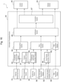
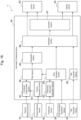
- Fig. 18 is a block diagram illustrating a functional configuration of an information processing device 54 of Embodiment 3.
- the information processing device 54 of Embodiment 3 performs the recognition of the dump truck 200 using only the point cloud data of the dump truck 200 and its surroundings among the point cloud data acquired by the external measuring device 70.
- the information processing device 54 of Embodiment 3 further includes a filter section 89 that extracts the point cloud data within a predetermined area including the estimated area calculated by the area estimation section 85 from the point cloud data acquired by the external measuring device 70.
- the recognition section 84 of Embodiment 3 recognizes the dump truck 200 from the point cloud data extracted by the filter section 89 and calculates the recognition area of the dump truck 200.
- the method of calculating the recognition area is the same as in Embodiment 1.
- the hydraulic excavator 1 of Embodiment 3 can remove the point cloud data that is a disturbance using the estimated area calculated by the area estimation section 85. As a result, the hydraulic excavator 1 of Embodiment 3 can improve the accuracy of the recognition process and shorten the processing time.
- the present invention is not limited to the above embodiments, but includes various modifications.
- the above embodiments are described in detail for the purpose of describing the invention in an easy-to-understand manner, and are not necessarily limited to those having all the described configurations. It is also possible to replace a part of a configuration of one embodiment with a configuration of another embodiment, and it is also possible to add a configuration of another embodiment to a configuration of one embodiment. It is also possible to add, delete, or replace some of configurations of each embodiment with other configurations.
- each of the above components, functions, processing sections, processing means, and the like may be realized in hardware by designing some or all of them, for example, in an integrated circuit.
- each of the above components, functions, and the like may be realized by software, in which a processor interprets and executes a program that realizes the respective function.
- Information such as programs, tapes, and files that realize each function can be placed in memory, hard disks, solid state drives (SSD), or other recording devices, or in recording media such as IC cards, SD cards, and DVDs.
- control lines and information lines are those considered necessary for illustrative purposes, and not all the control line and information lines are necessarily illustrated in the product. In reality, almost all the components may be considered to be interconnected.
Landscapes
- Engineering & Computer Science (AREA)
- Mining & Mineral Resources (AREA)
- Mechanical Engineering (AREA)
- Civil Engineering (AREA)
- General Engineering & Computer Science (AREA)
- Structural Engineering (AREA)
- Life Sciences & Earth Sciences (AREA)
- General Life Sciences & Earth Sciences (AREA)
- Paleontology (AREA)
- Operation Control Of Excavators (AREA)
- Component Parts Of Construction Machinery (AREA)
- Image Analysis (AREA)
Abstract
Provided is a work machine capable of appropriately controlling a loading work onto a carrier machine by verifying validity of a recognition result of the carrier machine. A hydraulic excavator includes an external measuring device that measures a surrounding environment, an information processing device that recognizes a dump truck present around the hydraulic excavator based on a measurement result of the external measuring device, a control device that controls an operation of the hydraulic excavator based on a recognition result of the information processing device, and a truck information acquisition device that acquires a position and vehicle class information of the dump truck through external communication. The information processing device corrects the recognition result of the dump truck based on the information acquired by the truck information acquisition device. The control device controls the operation of the hydraulic excavator based on the corrected recognition result of the dump truck.
Description
- The present invention relates to a work machine.
- Articulated work machines (for example, hydraulic excavators) with front work devices (for example, booms, arms, and attachments such as buckets) driven by hydraulic actuators are known. This type of work machine performs loading works to load excavated target objects such as earth and sand onto carrier machines (for example, dump trucks), which are machines to be loaded.
- When performing the loading works, if the front work device is swinged in a position where its height (for example, a bucket height) is lower than a height of the carrier machine, there is a possibility that the front work device may collide with the carrier machine. Therefore, there is a need for a function to assist an operation of an operator of a work machine performing the loading works and for technology that allows the work machine to perform the loading works automatically. When a work machine performs semi-automatic or fully automatic (hereinafter collectively referred to as "automatic") loading works, it is necessary for the work machine to accurately recognize a position and a posture of the carrier machine.
- As a conventional technology for recognizing the carrier machines, there is, for example, the technology described in
Patent Literature 1.Patent Literature 1 discloses an image processing system including a data acquisition section configured to acquire a captured image showing a loading/unloading target of a transporting material of a work machine; an area-identifying section configured to identify an area including the loading/unloading target from the captured image; and a loading/unloading target-identifying section configured to identifies at least one predetermined surface of the loading/unloading target from the area including the loading/unloading target. - Patent Literature 1:
JP 2020-126363 A - The technology disclosed in
Patent Literature 1 uses an image recognition system with machine learning to detect the position and the posture of the carrier machine from the image captured by a camera attached to the work machine in order to identify the carrier machine. However, it is difficult for the recognition system using the machine learning to guarantee validity of a recognition result and a recognition accuracy for sites or carrier machines for which no training data has been collected. - In addition, if a third-party system is incorporated as the recognition system for the carrier machine, details of an algorithm of the recognition system may not be disclosed to a development company of the work machine. It is not easy for the work machine developer to verify the recognition results of the recognition system. It is difficult for the work machine developer to determine in advance whether the recognition results of the recognition system can be used to properly control the loading work without colliding with the carrier machine.
- The present invention is made in view of the above problems to provide a work machine capable of appropriately controlling the loading work onto a carrier machine by accurately recognizing the position and the posture of the carrier machine in various situations.
- In order to achieve the above-described objective, a work machine according to the present invention is for loading a target object onto a carrier machine. The work machine includes an external measuring device, an information processing device, a control device, and a carrier machine information acquisition device. The external measuring device measures a surrounding environment of a body of the work machine. The information processing device recognizes the carrier machine present around the body based on a measurement result of the external measuring device. The control device controls an operation of the body based on a recognition result of the information processing device. The carrier machine information acquisition device acquires a position and vehicle class information of the carrier machine from an external source. The information processing device corrects a recognition result of the carrier machine based on the position and the vehicle class information of the carrier machine acquired by the carrier machine information acquisition device. The control device controls the operation of the body based on the corrected recognition result of the carrier machine.
- According to the present invention, it is possible to provide the work machine capable of appropriately controlling the loading works onto the carrier machines by accurately recognizing the position and the posture of the carrier machine in various situations.
- The problems, configurations and effects other than the above will be clarified by the description of the following embodiments.
-
-
Fig. 1 is a schematic side view of an exterior configuration of a hydraulic excavator as an example of a work machine ofEmbodiment 1. -
Fig. 2 is a block diagram illustrating a hydraulic system and a control system mounted on the hydraulic excavator illustrated inFig. 1 . -
Fig. 3 is a diagram illustrating an example of an operation of the hydraulic excavator illustrated inFig. 2 . -
Fig. 4 is a flowchart illustrating an example of the operation of the hydraulic excavator illustrated inFig. 2 . -
Fig. 5 is a block diagram illustrating a functional configuration of an information processing device illustrated inFig. 2 . -
Fig. 6 is a view illustrating respective coordinate systems set up on the hydraulic excavator, viewed from side. -
Fig. 7 is a view illustrating respective coordinate systems illustrated inFig. 6 , viewed from above. -
Fig. 8 is a view of a body coordinate system of a dump truck, viewed from side. -
Fig. 9 is a view illustrating the body coordinate system illustrated inFig. 8 , viewed from above. -
Fig. 10 is a flowchart illustrating an example of a recognition result verification process. -
Fig. 11 is a view illustrating an overlap degree of a recognition area and an estimated area. -
Fig. 12 is a view illustrating a table that defines criteria for determining validities of recognition results and methods of correction of recognition areas for respective tasks of the hydraulic excavator. -
Fig. 13 is a view illustrating a method of correcting the recognition area when acquiring a loading task. -
Fig. 14 is illustrating a method of correcting the recognition area when acquiring a reaching task. -
Fig. 15 is a view illustrating an example of a display device when a confidence of a recognition result is equal to or lower than a threshold. -
Fig. 16 a block diagram illustrating a functional configuration of an information processing device ofEmbodiment 2. -
Fig. 17 is a view illustrating a process of a truck posture estimation section illustrated inFig. 16 . -
Fig. 18 is a block diagram illustrating a functional configuration of an information processing device ofEmbodiment 3. - The embodiments of the invention will be described below using the drawings. Unless otherwise mentioned, the same configuration with the same numeral reference in each embodiment has the same function in each embodiment, and its description is omitted.
- A work machine according to the present embodiment is a work machine that performs loading works to load excavated target objects such as earth and sand onto the carrier machine, which is a machine to be loaded. In the following exemplary description, a hydraulic excavator including a bucket is used as the work machine, and a dump truck is used as the carrier machine. However, the work machine according to the present embodiment may be a hydraulic excavator including an attachment other than the bucket, or a work machine other than the hydraulic excavator. The carrier machine according to the present embodiment may be a carrier machine other than the dump truck.
-
Figs. 1 to 15 are used to describe thehydraulic excavator 1 ofEmbodiment 1. -
Fig. 1 is a schematic side view of an exterior configuration of ahydraulic excavator 1 as an example of a work machine ofEmbodiment 1. - The
hydraulic excavator 1 includes an articulatedfront work device 2 that holds the target object and turns in the vertical or front-back direction, and a machinemain body 3 that includes thefront work device 2. - The machine
main body 3 includes a lower travelingbody 5 that is driven by a right travelinghydraulic motor 4a and a left travelinghydraulic motor 4b provided on the right and left parts of the lower travelingbody 5, and anupper swing body 7 that is attached to an upper part of the lower travelingbody 5 via a swinging device and swinged by a swinginghydraulic motor 6 of the swinging device. In the present embodiment, the right travelinghydraulic motor 4a and the left travelinghydraulic motor 4b are also collectively referred to as "travelinghydraulic motors - The
front work device 2 is an articulated work apparatus constituted of a plurality of front members attached to a front of theupper swing body 7. Theupper swing body 7 on which thefront work device 2 is mounted swings. Thefront work device 2 includes aboom 8 vertically turnably connected to the front of theupper swing body 7, anarm 9 vertically turnably connected to a distal part of theboom 8, and abucket 10 vertically turnably connected to a distal part of thearm 9. - The
boom 8 is connected to theupper swing body 7 by aboom pin 8a and is turned by expansion and contraction of aboom cylinder 11. Thearm 9 is connected to the distal part of theboom 8 by anarm pin 9a and is turned by expansion and contraction of anarm cylinder 12. Thebucket 10 is connected to the distal part of thearm 9 by abucket pin 10a and abucket link 16, and is turned by expansion and contraction of abucket cylinder 13. - A
boom angle sensor 14 is attached to theboom pin 8a to detect a turn angle of theboom 8. Anarm angle sensor 15 is attached to thearm pin 9a to detect a turn angle of thearm 9. Abucket angle sensor 17 is attached to thebucket link 16 to detect a turn angle of thebucket 10. - Each turn angle of the
boom 8, thearm 9, and thebucket 10 may be acquired by detecting each angle of theboom 8, thearm 9, and thebucket 10 with respect to a reference plane such as the horizontal plane using an inertial measurement device and converting it to each of the turn angles. Each turn angle of theboom 8, thearm 9, and thebucket 10 may be acquired by detecting each stroke of theboom cylinder 11, thearm cylinder 12, and thebucket cylinder 13 with a stroke sensor and converting it to each of the turn angles. - An
inclination angle sensor 18 is attached to theupper swing body 7 to detect an inclination angle of the machinemain body 3 with respect to the reference plane such as the horizontal plane. A swinging device between thelower traveling body 5 and theupper swing body 7 includes aswing angle sensor 19 to detect a swing angle, which is a relative angle of theupper swing body 7 with respect to thelower traveling body 5. An angular speed sensor (not illustrated) is attached to theupper swing body 7 to detect an angular speed of theupper swing body 7. In the present embodiment, theboom angle sensor 14, thearm angle sensor 15, thebucket angle sensor 17, theinclination angle sensor 18, and theswing angle sensor 19 are also collectively referred to as a "posture detection device 53." Theposture detection device 53 detects the respective turn angles of thefront work device 2, the swing angle of theupper swing body 7, and the like. - In a cab provided on the
upper swing body 7, adisplay device 55 constituted of a touch screen or the like that can accept operator input is installed. In addition, an operating device for operating a plurality ofhydraulic actuators upper swing body 7. Specifically, the operating devices include a travelingright lever 23a for operating the right travelinghydraulic motor 4a, a travelingleft lever 23b for operating the left travelinghydraulic motor 4b, an operationright lever 22a for operating theboom cylinder 11 and thebucket cylinder 13, and an operationleft lever 22b for operating thearm cylinder 12 and the swinginghydraulic motor 6. In the present embodiment, the travelingright lever 23a, the travelingleft lever 23b, the operationright lever 22a, and the operation leftlever 22b are also collectively referred to as "operation levers 22, 23." - An
external measuring device 70 is also attached to theupper swing body 7 to measure a surrounding environment of a body of thehydraulic excavator 1. Theexternal measuring device 70 measures a depth (a distance to an object) of an object present around thehydraulic excavator 1. Theexternal measuring device 70 acquires depth information of the object as a measurement result. Theexternal measuring device 70 may be, for example, a light detection and ranging (LiDAR) or a stereo camera. A plurality of theexternal measuring device 70 may be installed on thehydraulic excavator 1. - A
positioning device 60 is also attached to theupper swing body 7 to measure a position and an orientation of thehydraulic excavator 1 at a site. Thepositioning device 60 acquires positioning information including the position and the orientation of thehydraulic excavator 1 at the site as the measurement result. Thepositioning device 60 may be, for example, a GNSS receiver, a total station (TS), or other surveying devices. Thepositioning device 60 may be, but is not limited to, for example, a camera fixed at the site. In this case, thepositioning device 60 may measure the position and the orientation of thehydraulic excavator 1 at the site based on the information calculated from the detected image of thehydraulic excavator 1. In this case, at least two of thepositioning devices 60 preferred to be provided to accurately measure the orientation of thehydraulic excavator 1. - A truck
information acquisition device 56 is also attached to theupper swing body 7 to acquire truck information, which includes position, posture, and vehicle class information of thedump truck 200, from an external source. The vehicle class information includes information on a vehicle type and dimensions of thedump truck 200. The truckinformation acquisition device 56 may be a communication terminal that performs wireless communication with a position and dispatch management system of thedump trucks 200, such as a fleet management system (FMS), for example. The truckinformation acquisition device 56 can acquire truck information by receiving the truck information of thedump trucks 200 transmitted from the position and dispatch management system of thedump trucks 200. The truckinformation acquisition device 56 may be configured as software implementing functions of the truckinformation acquisition device 56 and may be embedded in aninformation processing device 54. - Most of the position and dispatch management systems of the
dump trucks 200, such as FMSs, have an adjustment function to match the positional information of thedump truck 200 acquired from the GNSS receiver of thedump truck 200 with a route on a map. The truckinformation acquisition device 56 can acquire information regarding the position adjustment amount of thedump truck 200 based on the adjustment function and the truck information of thedump truck 200 at the same time from the position and dispatch management system. - A
task acquisition device 58 is also attached to theupper swing body 7 to acquire a task indicating the next operation contents (or the work contents) to be performed by thehydraulic excavator 1. Thetask acquisition device 58 may be, for example, a communication terminal that performs wireless communication with a management device that manages the work site. Thetask acquisition device 58 can acquire the tasks by receiving the tasks of thehydraulic excavator 1 transmitted from the management device. Thetask acquisition device 58 may be configured by a communication terminal shared with the truckinformation acquisition device 56. Thetask acquisition device 58 may be configured as software that implements functions of thetask acquisition device 58 and may be embedded in theinformation processing device 54. Thetask acquisition device 58 may also acquire the task by automatically determining the task from the operation of the operation levers 22, 23 by the operator. Thetask acquisition device 58 may be an input terminal that can be operated by the operator, and may acquire the task by accepting the operator input. The method of acquiring the tasks is not limited in the present embodiment. -
Fig. 2 is a block diagram illustrating a hydraulic system and a control system mounted on thehydraulic excavator 1 illustrated inFig. 1 . - An
engine 103, which is a prime mover mounted on theupper swing body 7, drives ahydraulic pump 102 and apilot pump 104. Thecontrol device 40 controls a turning movement of thefront work device 2, a traveling movement of thelower traveling body 5, and a swinging movement of the upper swing body 7 (that is, the movement of the body of thehydraulic excavator 1 constituted thereof) according to the operation information (operation amount and operation direction) of the operation levers 22, 23 by the operator. Specifically, thecontrol device 40 detects the operation information (operation amount and operation direction) of the operation levers 22, 23 by theoperator using sensors 52a to 52f such as rotary encoders or potentiometers, and outputs control commands to solenoidproportional valves 47a to 471 in accordance with the detected operation information. The solenoidproportional valves 47a to 471 are installed in apilot line 100 and are activated when the control commands from thecontrol device 40 is input, and output pilot pressures to aflow control valve 101 to activate theflow control valve 101. - The
flow control valve 101 controls a pressure oil supplied from thehydraulic pump 102 to each of the swinginghydraulic motor 6, thearm cylinder 12, theboom cylinder 11, thebucket cylinder 13, the right travelinghydraulic motor 4a, and the left travelinghydraulic motor 4b according to the pilot pressures from the solenoidproportional valves 47a to 471. The solenoidproportional valves flow control valve 101 to control the pressure oil supplied to the swinginghydraulic motor 6. The solenoidproportional valves flow control valve 101 to control the pressure oil supplied to thearm cylinder 12. The solenoidproportional valves flow control valve 101 to control the pressure oil supplied to theboom cylinder 11. The solenoidproportional valves flow control valve 101 to control the pressure oil supplied to thebucket cylinder 13. The solenoidproportional valves 47i, 47j output a pilot pressure to theflow control valve 101 to control the pressure oil supplied to the traveling right travelinghydraulic motor 4a. The solenoidproportional valves flow control valve 101 to control the pressure oil supplied to the traveling left travelinghydraulic motor 4b. - The
boom cylinder 11, thearm cylinder 12, and thebucket cylinder 13 expand and contract by the supplied pressure oils to rotate theboom 8, thearm 9, and thebucket 10, respectively. This changes the position and the posture of thebucket 10. The swinginghydraulic motor 6 is rotated by the supplied pressure oil to swing theupper swing body 7. The right travelinghydraulic motor 4a and the left travelinghydraulic motor 4b are rotate by the supplied pressure oils for causing thelower traveling body 5 to travel. - The
control device 40 can automatically (semi-automatically or fully automatically) control the movements of the body of the hydraulic excavator 1 (the turning movement of thefront work device 2, the traveling movement of thelower traveling body 5, and the swinging movement of the upper swing body 7) based on the recognition results of theinformation processing device 54. Theinformation processing device 54 recognizes thedump truck 200 present around thehydraulic excavator 1 based on the measurement result of theexternal measuring device 70. Theinformation processing device 54 is constituted of a computer including a Central Processing Unit (CPU) 73, a Random Access Memory (RAM) 72, a Read Only Memory (ROM) 71, and an external I/F (Interface) 74, and the like connected to each other by abus 75. Thecontrol device 40, thedisplay device 55, theexternal measuring device 70, thepositioning device 60, theposture detection device 53, thetask acquisition device 58, the truckinformation acquisition device 56, and a storage device 57 (for example, hard disk drive or large capacity flash memory) are connected to an external I/F 74. -
Fig. 3 is a diagram illustrating an example of an operation of thehydraulic excavator 1 illustrated inFig. 2 . - The
dump truck 200 stops at a predetermined position where thehydraulic excavator 1 can load the target object. Thetask acquisition device 58 of thehydraulic excavator 1 acquires a loading task for the next task, which is to load the excavated target objects such as earth and sand onto thedump truck 200. When the loading task is acquired, first, theexternal measuring device 70 of thehydraulic excavator 1 measures a vessel of thedump truck 200. Subsequently, theinformation processing device 54 of thehydraulic excavator 1 calculates a recognition area and an estimated area described below for apresence area 210 of thedump truck 200. Theinformation processing device 54 of thehydraulic excavator 1 calculates the position of thebucket 10 when loading the target object from thebucket 10 onto the vessel of the dump truck 200 (hereinafter also referred to as "loading position"). Based on the calculated recognition area and estimated area of thedump truck 200 and the loading position, thecontrol device 40 of thehydraulic excavator 1 outputs the control commands to move thebucket 10 to the loading position such that thefront work device 2 does not collide with thedump truck 200. This allows thehydraulic excavator 1 to automatically control the loading work appropriately without colliding with thedump truck 200. - In the present embodiment, as illustrated in
Fig. 3 , thedump truck 200 is assumed to be parked at a predetermined position where thehydraulic excavator 1 can load the target objects. Specifically, it is assumed that thedump truck 200 of the present embodiment has a position of thedump truck 200 at the work site controlled by the position and dispatch management system of thedump trucks 200, such as FMS. However, there is no limitation on how thedump truck 200 is controlled until thedump truck 200 stops at a predetermined position. For example, thedump truck 200 may be stopped at a predetermined position by the operator of thedump truck 200. In the present embodiment, the operator of thehydraulic excavator 1 may visually confirm that thedump truck 200 has stopped at the predetermined position, or theinformation processing device 54 may recognize that thedump truck 200 has stopped at the predetermined position based on the measurement result of theexternal measuring device 70. - The
external measuring device 70 ofFig. 3 is mounted to face the left side of thehydraulic excavator 1, but may be mounted to face the front of thehydraulic excavator 1. Furthermore, thehydraulic excavator 1 may further include theexternal measuring device 70 mounted to face the right side or rear of thehydraulic excavator 1. -
Fig. 4 is a flowchart illustrating an example of the operation of thehydraulic excavator 1 illustrated inFig. 2 . - In Step S111, the
task acquisition device 58 of thehydraulic excavator 1 acquires an excavation task to excavate the ground to be excavated. - In Step S112, the
control device 40 of thehydraulic excavator 1 controls the turning movement of thefront work device 2 to cause thehydraulic excavator 1 to perform the excavation operation according to the acquired excavation task. - In Step S113, the
task acquisition device 58 of thehydraulic excavator 1 acquires a loading task for loading the excavated target object such as earth and sand onto thedump truck 200. - In Step S114, the
control device 40 of thehydraulic excavator 1 controls the turning movement of thefront work device 2 and the swinging movement of theupper swing body 7 to cause thehydraulic excavator 1 to perform the loading operation according to the acquired loading task. - In Step S115, the
control device 40 of thehydraulic excavator 1 determines whether or not to terminate the loading onto thedump truck 200. The operator of thehydraulic excavator 1 may notify thecontrol device 40 that the loading onto thedump truck 200 is terminated by operating the certain operation levers 22, 23 or by entering information on thedisplay device 55, after visual confirmation. Thecontrol device 40 may determine to terminate the loading onto thedump truck 200 by the notification of these operations from the operator. Alternatively, thecontrol device 40 may determine to terminate the loading onto thedump truck 200 based on the determination result of a load determination device that measures the load of the target object loaded onto thedump truck 200 to determine that the load is appropriate. When the loading onto thedump truck 200 is determined to be terminated, thecontrol device 40 proceeds to Step S118. When the loading onto thedump truck 200 is determined not to be terminated, thecontrol device 40 proceeds to Step S116. - In Step S116, the
task acquisition device 58 of thehydraulic excavator 1 acquires a reaching task for moving thefront work device 2 to the next ground to be excavated. - In Step S117, the
control device 40 of thehydraulic excavator 1 controls the turning movement of thefront work device 2, the traveling movement of thelower traveling body 5, and the swinging movement of theupper swing body 7 to cause thehydraulic excavator 1 to perform a reaching operation according to the acquired reaching task. Thereafter, thecontrol device 40 proceeds to Step S111. - In Step S118, the
control device 40 of thehydraulic excavator 1 determines whether or not to terminate the work. Thecontrol device 40 may determine that the work is terminated when thetask acquisition device 58 acquires a work end notification. Alternatively, thecontrol device 40 may determine that the work is terminated when the operator or a manager stops theengine 103 of thehydraulic excavator 1. When the work is determined to be terminated, thecontrol device 40 interrupts the operation of thehydraulic excavator 1 to terminate the work. When the work is determined not to be terminated, thecontrol device 40 proceeds to Step S116. Thehydraulic excavator 1 continues the reaching operation, the excavation operation, and the loading operation. - The tasks and the operations of the
hydraulic excavator 1 are not limited to those illustrated inFig. 4 , and may include tasks and operations not illustrated inFig. 4 , such as moving or leveling, for example. - In the operation of the
hydraulic excavator 1, when thetask acquisition device 58 acquires each task, information such as the position, the posture and a shape of thedump truck 200 may be required. In this case, theinformation processing device 54 recognizes thedump truck 200 based on the measurement result of theexternal measuring device 70 each time thetask acquisition device 58 acquires each task. Theinformation processing device 54 then verifies whether the recognition result of thedump truck 200 is not valid to the extent that it cannot be corrected, or whether the recognition result of thedump truck 200 is valid to the extent that it can be corrected (hereinafter referred to as "verifying validity"). When the recognition result of thedump truck 200 is valid, theinformation processing device 54 corrects the recognition result. - In the present embodiment, a process of verifying the validity of the recognition result of the
dump truck 200 and correcting the recognition result is also referred to as the "recognition result verification process." The functions of theinformation processing device 54 that performs the recognition result verification process are described below. -
Fig. 5 is a block diagram illustrating a functional configuration of theinformation processing device 54 illustrated inFig. 2 .Fig. 6 is a view illustrating respective coordinatesystems 300 to 500 set up on thehydraulic excavator 1, viewed from side.Fig. 7 is a view illustrating the respective coordinatesystems 300 to 500 illustrated inFig. 6 , viewed from above. - The
information processing device 54 includes aposture calculation section 81, a coordinatetransformation section 82, a positioninginformation calculation section 83, atask acquisition section 80, arecognition section 84, anarea estimation section 85, averification section 86, and acorrection section 87. - In the
information processing device 54, the body coordinatesystem 400 illustrated inFigs. 6 and7 is preset as a reference coordinate system for identifying the positions and the postures of components of thehydraulic excavator 1. The body coordinatesystem 400 of thehydraulic excavator 1 in the present embodiment is defined as a right-hand coordinate system with the origin at the point where thelower traveling body 5 contact the ground G in aswing center line 120 of theupper swing body 7. The body coordinatesystem 400 of thehydraulic excavator 1 is defined with a forward direction of thelower traveling body 5 as a positive direction of the X-axis. The body coordinatesystem 400 of thehydraulic excavator 1 is defined with a direction in which theswing center line 120 extends upward as a positive direction of the Z-axis. The body coordinatesystem 400 of thehydraulic excavator 1 is defined as orthogonal to each of the X-and Z-axes, with a left direction as a positive direction of the Y-axis. In the body coordinatesystem 400 of thehydraulic excavator 1, the swing angle θsw of theupper swing body 7 is defined as 0 degrees when thefront work device 2 is parallel to the X-axis. - The present embodiment also defines a sensor coordinate
system 300, as illustrated inFigs. 6 and7 , as the reference coordinate system for theexternal measuring device 70. The present embodiment defines the site coordinatesystem 500, as illustrated inFigs. 6 and7 , as the reference coordinate system for the site. - The
posture calculation section 81 calculates the postures and the like of the components of thehydraulic excavator 1 in the body coordinatesystem 400 of thehydraulic excavator 1 from detection signals of theposture detection device 53. Specifically, theposture calculation section 81 calculates a turn angle θbm of theboom 8 with respect to the X-axis from the detection signal of the turn angle of theboom 8 output from theboom angle sensor 14. Theposture calculation section 81 calculates the turn angle θam of thearm 9 with respect to theboom 8 from the detection signal of the turn angle of thearm 9 output from thearm angle sensor 15. Theposture calculation section 81 calculates the turn angle θbk of thebucket 10 with respect to thearm 9 from the detection signal of the turn angle of thebucket 10 output from thebucket angle sensor 17. Theposture calculation section 81 calculates the swing angle θsw of theupper swing body 7 with respect to the X-axis (the lower traveling body 5) from the detection signal of the swing angle of theupper swing body 7 output from theswing angle sensor 19. Furthermore, theposture calculation section 81 calculates a turning angular velocity ωsw of theupper swing body 7 from the swing angle θsw of theupper swing body 7. - Furthermore, the
posture calculation section 81 calculates the inclination angle of the machine main body 3 (the lower traveling body 5) with respect to a reference plane DP from the detection signal of the inclination angle of the machinemain body 3 output from theinclination angle sensor 18. The reference plane DP is, for example, a horizontal plane orthogonal to the direction of gravity. The inclination angle includes a rotation angle θp about the Y-axis and a rotation angle θr about the X-axis. - The coordinate
transformation section 82 transforms the coordinate system expressing the depth information acquired by theexternal measuring device 70 from the sensor coordinatesystem 300 to the body coordinatesystem 400 of thehydraulic excavator 1 using the posture information of thehydraulic excavator 1 output from theposture calculation section 81. The depth information acquired by theexternal measuring device 70 is given as a set of three-dimensional point data (that is, point cloud data) expressed in the sensor coordinatesystem 300. - For example, the following Formulae (1) to (3) are used to convert point data Ps (Xs, Ys, Zs) in the sensor coordinate
system 300 to point data Pv (Xv, Yv, Zv) in the body coordinatesystem 400 of thehydraulic excavator 1.
[Math. 1]
[Math. 2]
[Math. 3]
- In the above-described Formulae (1) to (3), Rsv is a rotation matrix from the sensor coordinate
system 300 to the body coordinatesystem 400. αs, βs, and γs are the angles formed by respective axes of the external measuring device 70 (respective axes of the sensor coordinate system 300) in the body coordinatesystem 400. When theexternal measuring device 70 is fixed to thehydraulic excavator 1, for example, the angles formed by these angles can be measured in advance by measuring the attitude of theexternal measuring device 70 in the body coordinatesystem 400 and storing them in thestorage device 57 in advance. When theexternal measuring device 70 performs measurement while changing its posture with respect to thehydraulic excavator 1, a posture measuring sensor may be attached to theexternal measuring device 70 or the like, and the angle detected by the posture measuring sensor may be used to calculate a coordinate transformation matrix. θsw is the swing angle of theupper swing body 7 and is output from theposture calculation section 81. - In the above-described Formulae (1) to (3), Tsv is a translational vector from the origin of the body coordinate
system 400 to the origin of the sensor coordinatesystem 300. Lsx, Lsy, and Lsz are equal to the origin coordinates of the sensor coordinatesystem 300 as viewed from the body coordinatesystem 400. A mounting position of theexternal measuring device 70 is often fixed on thehydraulic excavator 1. Therefore, in such cases, the mounting position of theexternal measuring device 70 on thehydraulic excavator 1 can be measured in advance and stored in thestorage device 57 in advance. - The positioning
information calculation section 83 calculates the position of the origin of the body coordinatesystem 400 in the site coordinatesystem 500 of thehydraulic excavator 1 and an orientation θdir in the site coordinatesystem 500 of thefront work device 2 from the positioning information acquired by thepositioning device 60. - The
task acquisition section 80 acquires the next task to be performed by thehydraulic excavator 1 from thetask acquisition device 58. In the present embodiment, the tasks to be performed by thehydraulic excavator 1 include the excavation task, the loading task, and the reaching task. The excavation task is a task that specifies the excavation operation until thehydraulic excavator 1 excavates the ground to be excavated and holds the target object such as earth and sand in thebucket 10. The loading task is a task that specifies the loading operation from a state in which thehydraulic excavator 1 terminates the excavation operation until thebucket 10 is moved to above the vessel of thedump truck 200 and the target object is released from thebucket 10 onto the vessel. The reaching task is a task that specifies the reaching operation in which thehydraulic excavator 1 moves thebucket 10 from the state in which the loading operation is terminated to the position in which the ground to be excavated next is located. The tasks performed by thehydraulic excavator 1 are not limited to these tasks. For example, a leveling task that specifies a leveling operation in which thehydraulic excavator 1 levels the surrounding ground until thedump truck 200 stops at a predetermined position at the site, and/or a leveling task that specifies a moving operation in which thehydraulic excavator 1 changes the ground to be excavated may be included. - The
recognition section 84 recognizes thedump truck 200 from the measurement results of theexternal measuring device 70. Specifically, therecognition section 84 recognizes the position, the posture, and the shape of thedump truck 200 using the point cloud data, which are acquired as the measurement result of theexternal measuring device 70 and converted to the body coordinatesystem 400 by the coordinatetransformation section 82. Therecognition section 84 then calculates a recognition area, which is an area where the recognizeddump truck 200 is present. In other words, the recognition area is the recognition result of therecognition section 84 for thepresence area 210 of thedump truck 200. - A method of calculating the recognition area of the
dump truck 200 by therecognition section 84 is, for example, to maintain a 3-D mesh model of thedump truck 200 measured in advance in thestorage device 57. Then, the position, the posture, and the shape are collated between the point cloud data converted to the body coordinatesystem 400 acquired from the coordinatetransformation section 82 and the 3D mesh model. As a result, therecognition section 84 can calculate the position, the posture, and the shape of thetarget dump truck 200, and thus can calculate the recognition area of thedump truck 200. The method of calculating the recognition area of thedump truck 200 is not limited thereto, and may be, for example, a method of calculating the recognition area of thedump truck 200 by a process of extracting a specific plane of thedump truck 200 from the point cloud data acquired from theexternal measuring device 70. Alternatively, a neural network that calculates the recognition area of thedump truck 200 from the point cloud data including thedump truck 200 may be constructed in advance, and the features of thedump truck 200 to be recognized may be calculated using a discriminator that has been machine-learned. - In the present embodiment, the position, the posture, and the
presence area 210 of thedump truck 200 are defined as follows. -
Fig. 8 is a view of a body coordinatesystem 600 of thedump truck 200, viewed from side.Fig. 9 is a view illustrating the body coordinatesystem 600 illustrated inFig. 8 , viewed from above. - In the present embodiment, the body coordinate
system 600 of thedump truck 200 has the center of the rear axle of thedump truck 200 as the origin, and the X-axis is a direction from the rear wheels to the front wheels, the Y-axis is a direction where the rear axle extends, and the Z-axis is a direction of the height of thedump truck 200. Assume that the position of thedump truck 200 designates the origin Pd (Xd, Yd, Zd) of the body coordinatesystem 600. Assume that the posture of thedump truck 200 refers to the angle θd (θroll, θpitch, θyaw) formed by the respective axes of the site coordinatesystem 500 and the respective axes of the body coordinatesystem 600 of thedump truck 200. Assume that thepresence area 210 of thedump truck 200 refers to a rectangular area Sd (Pd1 to Pd4) with the points Pd1 to Pd4 at the four corners of the vessel of thedump truck 200 as vertices. Thepresence area 210 of thedump truck 200 is not limited thereto, and may be, for example, a hexahedron (for example, a rectangle or cube) that encompasses theentire dump truck 200. In the present embodiment, assume that the recognition area of thedump truck 200, which is the recognition result of therecognition section 84 for thepresence area 210 of thedump truck 200, is Sdr (Pdr1 to Pdr4). - The
area estimation section 85 calculates an estimated area, which is an area where thedump truck 200 is estimated to be present, from the position and the vehicle class information (truck information) of thedump truck 200 acquired by the truckinformation acquisition device 56. In other words, the estimated area is an estimation result of thearea estimation section 85 for thepresence area 210 of thedump truck 200. The estimated area is calculated for comparison with the recognition area of thedump truck 200 calculated by therecognition section 84 in order to verify validity of the recognition result of thedump truck 200. - The method of calculating the estimated area of the
dump truck 200 by thearea estimation section 85 stores, for example, a method of calculating the estimated area of thedump truck 200 from the truck information in thestorage device 57 in advance for each vehicle type. Then, using the truck information acquired by the truckinformation acquisition device 56 and the calculation method corresponding to the truck information, the estimated area in the site coordinatesystem 500 of thetarget dump truck 200 is calculated and converted to the body coordinatesystem 400 of thehydraulic excavator 1. This allows thearea estimation section 85 to calculate the estimated area of thedump truck 200 that can be compared with the recognition area of thedump truck 200 calculated by therecognition section 84. In the present embodiment, assume that the estimated area of thedump truck 200, which is the estimation result of thearea estimation section 85 for thepresence area 210 of thedump truck 200, is Sde (Pde1 to Pde4). - The transformation from the site coordinate
system 500 to the body coordinatesystem 400 of thehydraulic excavator 1 can be performed using the following formulae. For example, the following Formulae (4) to (6) are used to convert from the point data Pv (Xv, Yv, Zv) in the body coordinatesystem 400 of thehydraulic excavator 1 to the point data Pg (Xg, Yg, Zg) in the site coordinatesystem 500.
[Math. 4]
[Math. 5]
[Math. 6]
- In the above-described Formulae (4) to (6), Rvg is a rotation matrix from the body coordinate
system 400 to the site coordinatesystem 500. θr, θp, and θy are the angles formed by respective axes of the body coordinatesystem 400 in the site coordinatesystem 500. These angles can be calculated using the values calculated by theposture calculation section 81, the swing angle, the inclination angle of the machinemain body 3, and the orientation calculated by the positioninginformation calculation section 83. - In the above-described Formulae (4) to (6), Tvg is a translational vector from the origin of the site coordinate
system 500 to the origin of the body coordinatesystem 400. X0, y0, z0 are equal to the origin coordinates of the body coordinatesystem 400 as viewed from the site coordinatesystem 500. For Tvg, a calculation result of the positioninginformation calculation section 83 can be used. - The
area estimation section 85 can adjust the position of thedump truck 200 included in the truck information using the position adjustment amount of thedump truck 200 that was simultaneously acquired with the truck information by the truckinformation acquisition device 56. Thearea estimation section 85 can then calculate the estimated area of thedump truck 200 from the adjusted position of thedump truck 200. - The
verification section 86 verifies the validity of the recognition result of thedump truck 200 based on the recognition area calculated by therecognition section 84 and the estimated area calculated by thearea estimation section 85. Specifically, theverification section 86 calculates a confidence of the recognition result of thedump truck 200 by comparing the recognition area with the estimated area, and verifies the validity of the recognition result of thedump truck 200 according to the calculated confidence. In detail, theverification section 86 calculates an overlap degree, which indicates a degree of an overlap between the recognition area and the estimated area, as the confidence of the recognition result of thedump truck 200. When the calculated overlap degree is higher than a threshold, theverification section 86 determines that the recognition result of thedump truck 200 is valid (correctable). In this case, theverification section 86 can change the threshold of the overlap degree, which is a criterion for determining the validity of the recognition result, according to the task acquired by thetask acquisition section 80. - The
correction section 87 corrects the recognition area calculated by therecognition section 84 based on the estimated area calculated by thearea estimation section 85. Specifically, thecorrection section 87 compares the recognition area calculated by therecognition section 84 with the estimated area calculated by thearea estimation section 85 and corrects the recognition area calculated by therecognition section 84. Accordingly, thecorrection section 87 corrects the recognition result of thedump truck 200. At this time, thecorrection section 87 can change the correction method of the recognition area (the recognition result) calculated by therecognition section 84 according to the task acquired by thetask acquisition section 80. - The
information processing device 54 uses theverification section 86 and thecorrection section 87 to verify the validity of the recognition result of thedump truck 200, and performs the recognition result verification process to correct the recognition result. The recognition result verification process is described in detail below. -
Fig. 10 is a flowchart illustrating an example of the recognition result verification process.Fig. 11 is a view illustrating the overlap degree of the recognition area and the estimated area.Fig. 12 is a view illustrating a table that defines criteria for determining the validities of the recognition results and the methods of correction of the recognition areas for the respective tasks of thehydraulic excavator 1.Fig. 13 is a view illustrating the method of correcting the recognition area when acquiring the loading task.Fig. 14 is illustrating a method of correcting the recognition area when acquiring the reaching task.Fig. 15 is a view illustrating an example of thedisplay device 55 when the confidence of the recognition result is equal to or lower than the threshold. - In Step S121, the
verification section 86 of theinformation processing device 54 acquires the task acquired by thetask acquisition section 80. - In Step S122, the
verification section 86 of theinformation processing device 54 acquires the recognition area calculated by therecognition section 84. - In Step S123, the
verification section 86 of theinformation processing device 54 acquires the estimated area calculated by thearea estimation section 85. - In Step S124, the
verification section 86 of theinformation processing device 54 calculates the confidence of the recognition result of thedump truck 200. As illustrated inFig. 11 , in the present embodiment, theverification section 86 calculates the overlap degree Acover, which indicates the overlap between the recognition area calculated by therecognition section 84 and the estimated area calculated by thearea estimation section 85, as the confidence of the recognition result of thedump truck 200. The overlap degree Acover is given by the following Formula (7).
[Math. 7]
- In the above-described Formula (7), Sde indicates an area of the estimated area calculated by the
area estimation section 85. Scover indicates an area of the area where the recognition area (Sdr) calculated by therecognition section 84 and the estimated area (Sde) calculated by thearea estimation section 85 overlap. Scover can be attributed, for example, to a problem of finding an area of an intersection of two convex polygons, for example, and can be solved as a numerical calculation problem. - In Step S125, the
verification section 86 of theinformation processing device 54 determines whether the calculated overlap degree Acover is higher than a threshold Ath. Accordingly, theverification section 86 verifies the validity of the recognition result of thedump truck 200. When the calculated overlap degree Acover is higher than the threshold Ath, theverification section 86 determines that the recognition result of thedump truck 200 is valid (correctable) and proceeds to Step S126. When the calculated overlap degree Acover is equal to or lower than the threshold Ath, theverification section 86 determines that the recognition result of thedump truck 200 is not valid (not correctable) and proceeds to Step S127. - Here, the
verification section 86 can change the threshold Ath of the overlap degree Acover, which is the criterion for determining the validity of the recognition result, according to the task acquired by thetask acquisition section 80, as illustrated inFig. 12 . The table illustrated inFig. 12 is stored in thestorage device 57 in advance. As illustrated inColumn 1201 of the table illustrated inFig. 12 , when the task acquired by thetask acquisition section 80 is the loading task, theverification section 86 sets Ath1 as the threshold Ath. When the task acquired by thetask acquisition section 80 is the reaching task, theverification section 86 sets Ath2 as the threshold Ath. Ath1 and Ath2 are preferred to be determined with the calculation accuracy of the respective areas of thearea estimation section 85 and therecognition section 84 during the functional verification conducted in advance, the presence or absence of the target object in thebucket 10 when the task is acquired, the distance between thefront work device 2 and thedump truck 200, and other factors taken into account. - In the loading operation specified by the loading task, the
hydraulic excavator 1 starts in a state where the target object is in thebucket 10 and the distance between thefront work device 2 and thedump truck 200 is large. As a result, the damage caused when thefront work device 2 collides with thedump truck 200 is considered to be greater during the loading operation than during the reaching operation. Therefore, the threshold Ath1 set when the loading task is acquired preferred to be the same value or higher than the threshold Ath2 set when the reaching task is acquired. - In Step S126, the
correction section 87 of theinformation processing device 54 corrects the recognition result of thedump truck 200. Specifically, thecorrection section 87 corrects the recognition area calculated by therecognition section 84. Thecorrection section 87 then outputs the determination result that the recognition result of thedump truck 200 is valid (correctable), the confidence (the overlap degree) of the recognition result, and the recognition area after the correction, to thecontrol device 40. Furthermore, thecorrection section 87 may display the information output to thecontrol device 40 on thedisplay device 55 to notify the operator, or transmit the information to the management device that manages the work site to notify the manager. Theinformation processing device 54 then terminates the recognition result verification process illustrated inFig. 10 . - Here, the
correction section 87 can change the correction method of the recognition area calculated by therecognition section 84 according to the task acquired by thetask acquisition section 80, as illustrated inFig. 12 . As indicated inColumn 1202 of the table illustrated inFig. 12 , when the task acquired by thetask acquisition section 80 is the loading task, thecorrection section 87 corrects the recognition area calculated by therecognition section 84 to be an area (Sdc) that encompasses the recognition area (Sdr) and the estimated area (Sde) as illustrated inFig. 13 . The area encompassing the recognition area (Sdr) and the estimated area (Sde) is the area (Sdc) that encompasses an OR(Union) area occupied by the recognition area (Sdr) or the estimated area (Sde). In an example ofFig. 13 , thecorrection section 87 corrects the recognition area (Sdr) calculated by therecognition section 84 to a rectangular area (Sdc) that encompasses the recognition area (Sdr) and the estimated area (Sde) and has the smallest area. - In the loading operation specified by the loading task, the
hydraulic excavator 1 moves thebucket 10 from the ground outside thedump truck 200 toward above the vessel inside of thedump truck 200 to the loading position. Therefore, when the recognition area calculated by therecognition section 84 is corrected to an area that encompasses the recognition area and the estimated area, the risk of thefront work device 2 moving from the outside to the inside of thedump truck 200 colliding with thedump truck 200 during the loading operation is reduced. Therefore, when the task acquired by thetask acquisition section 80 is the loading task, thecorrection section 87 corrects the recognition area calculated by therecognition section 84 to be the area that encompasses the recognition area and the estimated area. - The
correction section 87 can calculate the position in the height direction (the Z-axis direction) of the recognition area after the correction as follows. That is, thecorrection section 87 can use the maximum value of the Z-axis component of the coordinates of respective vertices of the recognition area and the estimated area as the position of the recognition area in the height direction after the correction, in order to avoid the collision between thefront work device 2 and thedump truck 200. - The
correction section 87 can calculate the orientation vdc of the recognition area after the correction, using the orientation vector vdr of the recognition area and the orientation vector vde of the estimated area, for example, from Formulae (8) to (9) below.
[Math. 8]
[Math. 9]
- Δdr (Δxdr, Δydr, Δzdr) used in the calculation of the gain Gk in the above-described Formula (9) is information on the calculation accuracy of the recognition area in the
recognition section 84. As Δdr, for example, the measurement accuracy of theexternal measuring device 70 and the calculation accuracy of therecognition section 84, which are measured in advance can be used. When the discriminator using the machine learning is used in the recognition algorithm of therecognition section 84, the information on the recognition confidence output by the discriminator may be used as Δdr. - Δde (Δxde, Δyde, Δzde) used in the calculation of the gain Gk in the above-described Formula (9) is information on the calculation accuracy of the estimated area in the
area estimation section 85. As Δde, the position adjustment amount of thedump truck 200 that can be acquired simultaneously with the truck information by the truckinformation acquisition device 56 can be used. In other words, thecorrection section 87 can correct the recognition area calculated by therecognition section 84 using the position adjustment amount of thedump truck 200 acquired by the truckinformation acquisition device 56. When the truckinformation acquisition device 56 is unable to acquire the position adjustment amount, as Δde, the result of a prior investigation of the error of the positioning information acquired by thepositioning device 60 at the site of thehydraulic excavator 1 can be used. - The
correction section 87 also calculates the loading position Pdc (Xdc, Ydc, Zdc) of thebucket 10. Specifically, thecorrection section 87 calculates, for example, the center position Pdr0 of the vessel in the recognition area calculated by therecognition section 84 and the center position Pde0 of the vessel in the estimated area calculated by thearea estimation section 85. Thecorrection section 87 can then use the center position Pdr0 of the vessel in the recognition area and the center position Pde0 of the vessel in the estimated area to calculate, for example, from the following Formula (10).
[Math. 10]
- In the above-described Formula (10), the gain Gk is given by the above-described Formula (9) including Δde. In other words, the
correction section 87 can calculate the loading position of thebucket 10 based on the position adjustment amount of thedump truck 200 acquired by the truckinformation acquisition device 56, the recognition area, and the estimated area. Thecorrection section 87 outputs the calculated loading position of thebucket 10 to thecontrol device 40. - On the other hand, when the task acquired by the
task acquisition section 80 is the reaching task, thecorrection section 87 corrects the recognition area (Sdr) calculated by therecognition section 84 such that the recognition area (Sdr) becomes the area (Sdc) encompassed by the overlapping area of the recognition area (Sdr) and the estimated area (Sde) as illustrated inFig. 14 . The area (Sdc) encompassed by the area where the recognition area (Sdr) and the estimated area (Sde) overlap is the area (Sdc) encompassed by an AND area occupied by both the recognition area (Sdr) and the estimated area (Sde). In an example inFig. 14 , thecorrection section 87 corrects the recognition area (Sdr) calculated by therecognition section 84 to the rectangular area (Sdc) that encompasses the recognition area (Sdr) and the estimated area (Sde) and has the largest area. - In the reaching operation specified by the reaching task, the
hydraulic excavator 1 moves thebucket 10 from the loading position above the vessel inside thedump truck 200 to the ground outside thedump truck 200. Therefore, when the recognition area calculated by therecognition section 84 is corrected to the area encompassed by the overlapping area of the recognition area and the estimated area, the risk of thefront work device 2 moving from the inside to the outside of thedump truck 200 colliding with thedump truck 200 during the reaching operation is reduced. Therefore, when the task acquired by thetask acquisition section 80 is the reaching task, thecorrection section 87 corrects the recognition area calculated by therecognition section 84 such that the recognition area becomes the area encompassed by the area overlapping the recognition area and the estimated area. - Similarly to when the loading task is acquired, the
correction section 87 can use the maximum value of the Z-axis component of the coordinates of respective vertices of the recognition area and the estimated area as the position of the recognition area in the height direction (Z-axis direction) after the correction. Similarly to when the loading task is acquired, thecorrection section 87 can calculate the orientation of the recognition area after the correction from the above-described Formulae (8) to (9). - In Step S127, the
verification section 86 of theinformation processing device 54 outputs the determination result that the recognition result of thedump truck 200 is not valid (not correctable), the confidence (the overlap degree) of the recognition result, the recognition area, and the estimated area, to thecontrol device 40. Furthermore, theverification section 86 notifies the operator by displaying the information output to thecontrol device 40 on thedisplay device 55, and/or notifies the manager by transmitting the information to the management device that manages the work site. At this time, theverification section 86 confirms with the operator or a user such as the manage whether or not thehydraulic excavator 1 is allowed to be continued to operate. - For example, as illustrated in
Fig. 15 , theverification section 86 displays ascreen 551 on thedisplay device 55 to notify the user of the determination result that the recognition result of thedump truck 200 is not valid (not correctable) and to confirm with the user whether the operation of thehydraulic excavator 1 is allowed to be continued. Thescreen 551 includes amessage 552 to notify the user of the determination result that the recognition result of thedump truck 200 is not valid (not correctable) and to confirm with the user whether the operation of thehydraulic excavator 1 is allowed to be continued. Thescreen 551 includes abutton 553 for the user to input the confirmation result that the operation of thehydraulic excavator 1 is to be continued. Thescreen 551 includes abutton 554 for the user to input the confirmation result that the operation of thehydraulic excavator 1 is not to be continued. Thescreen 551 includes abutton 555 for the user to input that thehydraulic excavator 1 is to be switched from the automatic control to the manual operation by the operator. Thescreen 551 also notifies the user of the positional relationship between thedump truck 200 and thehydraulic excavator 1 by indicating the calculation results of the recognition area (Sdr) and the estimated area (Sde) of thedump truck 200. - When the
verification section 86 receives the confirmation result from the user as to whether or not the continuation is allowed, it outputs the confirmation result to thecontrol device 40. Theinformation processing device 54 then terminates the recognition result verification process illustrated inFig. 10 . - The
control device 40 controls the movements of the body of the hydraulic excavator 1 (for example, the turning movement of thefront work device 2, the traveling movement of thelower traveling body 5, and the swinging movement of the upper swing body 7) based on the result of the validation of the recognition result of thedump truck 200 by theinformation processing device 54. - When the recognition result is valid (correctable), the
control device 40 controls the operation of thehydraulic excavator 1 based on the task acquired by thetask acquisition device 58 and the corrected recognition area output from theinformation processing device 54. Specifically, when the loading task is acquired, thecontrol device 40 controls the loading operation of thehydraulic excavator 1 such that thefront work device 2 moves on a trajectory where it does not collide with thedump truck 200 before thebucket 10 reaches the loading position from the ground. When the reaching task is acquired, thecontrol device 40 controls the reaching operation of thehydraulic excavator 1 such that thefront work device 2 moves on a trajectory where it does not collide with thedump truck 200 before thebucket 10 reaches the ground to be excavated next from the loading position. - When the recognition result is not valid (not correctable), the
control device 40 controls the operation of thehydraulic excavator 1 upon the confirmation result output from theinformation processing device 54 as to whether the operation of thehydraulic excavator 1 is allowed to be continued. - As described above, the
hydraulic excavator 1 ofEmbodiment 1 is the work machine that loads the target object onto thedump truck 200. Thehydraulic excavator 1 includes theexternal measuring device 70 that measures the surrounding environment of the body of thehydraulic excavator 1. Thehydraulic excavator 1 includes theinformation processing device 54 that recognizes thedump truck 200 present around the body of thehydraulic excavator 1 based on the measurement result of theexternal measuring device 70. Thehydraulic excavator 1 includes thecontrol device 40 that controls the operation of the body of thehydraulic excavator 1 based on the recognition result of theinformation processing device 54. Thehydraulic excavator 1 includes the truckinformation acquisition device 56 that acquires the position and the vehicle class information of thedump truck 200 from the external source. Theinformation processing device 54 corrects the recognition result of thedump truck 200 based on the position and the vehicle class information of thedump truck 200 acquired by the truckinformation acquisition device 56. Thecontrol device 40 controls the operation of the body of thehydraulic excavator 1 based on the corrected recognition result of thedump truck 200. - As a result, the
hydraulic excavator 1 ofEmbodiment 1 can control the loading operation and the like for thedump truck 200 using the accurate recognition result of thedump truck 200 in various situations. Thus, according toEmbodiment 1, it is possible to provide the work machine that can appropriately control the loading work onto the carrier machine by accurately recognizing the position and the posture of the carrier machine in various situations. - Conventionally, when the
hydraulic excavator 1 performs the loading operation for thedump truck 200, it was difficult to verify the recognition result of thedump truck 200 from the measurement result of theexternal measuring device 70. In particular, with the recognition system using machine learning, it is difficult to properly evaluate uncertainty of the recognition result for the site or thedump truck 200 for which no training data has been collected. Furthermore, when the development company of thehydraulic excavator 1 and the recognition system development company are different, details of the recognition system algorithm might not be disclosed to the development company of thehydraulic excavator 1. It is difficult for the development company of thehydraulic excavator 1 to perform a sufficient risk assessment in advance to determine whether the recognition result of the recognition system can be used to properly control the loading work without colliding with thedump truck 200. - In contrast, the
hydraulic excavator 1 ofEmbodiment 1 can verify the validity of the recognition result of thedump truck 200 based on information from a third party acquired by the truckinformation acquisition device 56, and can correct the recognition result. Then, thehydraulic excavator 1 ofEmbodiment 1 can appropriately control the loading operation and the like based on the corrected recognition result. In other words, thehydraulic excavator 1 ofEmbodiment 1 can control the movement of the body of thehydraulic excavator 1 based on the accurate recognition result of the position, the posture, and the like of thedump truck 200. Therefore, thehydraulic excavator 1 ofEmbodiment 1 can reduce the risk of the collision with thedump truck 200, and control the loading operation and the reaching operation, thereby improving the safety and productivity of the loading work. Thus, according toEmbodiment 1, it is possible to provide thehydraulic excavator 1 that can appropriately control the loading work onto thedump truck 200 by accurately recognizing the position and the posture of thedump truck 200 in various situations. - Furthermore, the
information processing device 54 includes therecognition section 84 that recognizes thedump truck 200 from the measurement result of theexternal measuring device 70 and calculates the recognition area, which is an area in which the recognizeddump truck 200 is present. Theinformation processing device 54 includes thearea estimation section 85 that calculates the estimated area, which is an area where thedump truck 200 is estimated to be present, based on the position and the vehicle class information of thedump truck 200 acquired by the truckinformation acquisition device 56. Theinformation processing device 54 includes thecorrection section 87 that corrects the recognition area based on the estimated area. - This allows the
hydraulic excavator 1 ofEmbodiment 1 to correct the recognition result based on a relatively simple indicator, which is the presence area of thedump truck 200. Therefore, thehydraulic excavator 1 ofEmbodiment 1 can accurately and easily recognize the position and the posture of thedump truck 200. Thehydraulic excavator 1 ofEmbodiment 1 can further improve the safety and productivity of the loading work. Thus, according toEmbodiment 1, it is possible to easily provide thehydraulic excavator 1 that can appropriately control the loading work onto thedump truck 200 by accurately recognizing the position and the posture of thedump truck 200 in various situations. - Furthermore, the information processing device 54 (the verification section 86) calculates the confidence of the recognition result of the
dump truck 200 by comparing the recognition area with the estimated area. Thecorrection section 87 corrects the recognition area according to the calculated confidence. - As a result, the
hydraulic excavator 1 ofEmbodiment 1 can quantitatively verify the validity of the recognition result of thedump truck 200, and can accurately and precisely correct the recognition area. Thehydraulic excavator 1 ofEmbodiment 1 can further improve the safety and productivity of the loading work. Thus, according toEmbodiment 1, it is possible to provide thehydraulic excavator 1 that can further appropriately control the loading work onto thedump truck 200 by accurately and precisely recognizing the position and the posture of thedump truck 200 in various situations. - Furthermore, the information processing device 54 (the verification section 86) calculates the overlap degree, which indicates the degree of overlap between the recognition area and the estimated area, as the confidence of the recognition result. The
correction section 87 corrects the recognition area according to the calculated overlap degree. - As a result, the
hydraulic excavator 1 ofEmbodiment 1 can calculate the confidence of the recognition result with a clear standard, and the recognition area can be corrected more accurately and precisely. Thehydraulic excavator 1 ofEmbodiment 1 can further improve the safety and productivity of the loading work. Thus, according toEmbodiment 1, it is possible to provide thehydraulic excavator 1 that can control the loading work onto thedump truck 200 more appropriately by recognizing the position and the posture of thedump truck 200 more accurately and precisely in various situations. - Furthermore, the truck
information acquisition device 56 further acquires information on the position adjustment amount of thedump truck 200. Thearea estimation section 85 calculates the estimated area using the position adjustment amount acquired by the truckinformation acquisition device 56. - As a result, the
hydraulic excavator 1 ofEmbodiment 1 can calculate the estimated area using values that are more realistic than the error in the positional information of thedump truck 200 acquired through prior verification and the like. Therefore, thehydraulic excavator 1 ofEmbodiment 1 can further accurately correct the recognition area. Thehydraulic excavator 1 ofEmbodiment 1 can further improve the safety and productivity of the loading work. Thus, according toEmbodiment 1, thehydraulic excavator 1 can further accurately recognize the position and the posture of thedump truck 200 in various situations, thereby enabling further appropriate control of the loading work onto thedump truck 200. - Furthermore, the
information processing device 54 further includes thetask acquisition section 80 that acquires the next task to be performed by thehydraulic excavator 1. Thecorrection section 87 changes the correction method of the recognition area according to the acquired task. - As a result, the
hydraulic excavator 1 ofEmbodiment 1 can correct it to the optimal recognition area for each of the acquired tasks, allowing thehydraulic excavator 1 to perform the optimal operation for each of the acquired tasks. Thehydraulic excavator 1 ofEmbodiment 1 can further improve the safety and productivity of loading works. Thus, according toEmbodiment 1, it is possible to provide thehydraulic excavator 1 that can further control the loading work onto thedump truck 200 more appropriately by further accurately recognizing the position and the posture of thedump truck 200 in various situations. - Furthermore, the
correction section 87 corrects the recognition area to be an area that encompasses the recognition area and the estimated area when the loading task for loading the target object onto thedump truck 200 is acquired. - This allows the
hydraulic excavator 1 ofEmbodiment 1 to further reduce the risk of thefront work device 2, which moves from the outside to the inside of thedump truck 200 during the loading operation, colliding with thedump truck 200. Thehydraulic excavator 1 ofEmbodiment 1 can further improve the safety and productivity of the loading work. Thus, according toEmbodiment 1, it is possible to provide thehydraulic excavator 1 that can further appropriately control the loading work onto thedump truck 200 by accurately recognizing the position and the posture of thedump truck 200 in various situations. - Furthermore, the
hydraulic excavator 1 further includes thebucket 10 that holds the target object. The truckinformation acquisition device 56 further acquires the position adjustment amount of thedump truck 200. When the loading task for loading the object onto thedump truck 200 is acquired, thecorrection section 87 calculates the position of thebucket 10 when loading the target object from thebucket 10 onto thedump truck 200 based on the position adjustment amount acquired by the truckinformation acquisition device 56, the recognition area, and the estimated area. Thecontrol device 40 controls the loading operation of thehydraulic excavator 1 based on the position of thebucket 10 calculated by thecorrection section 87. - As a result, the
hydraulic excavator 1 ofEmbodiment 1 can make the control target value of thecontrol device 40 as the loading position of thebucket 10 more reasonable. Therefore, thehydraulic excavator 1 ofEmbodiment 1 can further improve the safety and productivity of the loading work. Thus, according toEmbodiment 1, it is possible to provide thehydraulic excavator 1 that can further appropriately control the loading work onto thedump truck 200 by accurately recognizing the position and the posture of thedump truck 200 in various situations. - Furthermore, the
correction section 87 corrects the recognition area such that the recognition area becomes an area encompassed by the overlapping area between the recognition area and the estimated area when the reaching task, which is performed after the termination of the loading task for loading the target object onto thedump truck 200, is acquired. - As a result, the
hydraulic excavator 1 ofEmbodiment 1 can further reduce the risk of thefront work device 2, which moves from the inside to the outside of thedump truck 200 during the reaching operation, colliding with thedump truck 200. Therefore, thehydraulic excavator 1 ofEmbodiment 1 can further improve the safety and productivity of the loading work. Thus, according toEmbodiment 1, it is possible to provide thehydraulic excavator 1 that can further appropriately control the loading work onto thedump truck 200 by accurately recognizing the position and the posture of thedump truck 200 in various situations. - Furthermore, when the information processing device 54 (the verification section 86) has determined that the recognition result of the
dump truck 200 is not correctable, it notifies the user of the determination result that the recognition result is not correctable and displays thescreen 551 on thedisplay device 55 to confirm with the user whether the operation of the body of thehydraulic excavator 1 is allowed to be continued. When the information processing device 54 (the verification section 86) receives the confirmation result from the user as to whether or not the operation is allowed be continued, it outputs the confirmation result to thecontrol device 40. Thecontrol device 40 controls the operation of the body of thehydraulic excavator 1 according to the confirmation result. - In the
hydraulic excavator 1, there is a possibility that the recognition result of thedump truck 200 might be determined to be not correctable due to the influence of the site environment, such as sand and dust present in the surrounding environment, sensor malfunction, or the like. Even in such a case, thehydraulic excavator 1 ofEmbodiment 1 is allowed to be continued to operate thehydraulic excavator 1 under appropriate determination by seeking instructions from the operator or the manager. Thus, according toEmbodiment 1, it is possible to provide thehydraulic excavator 1 that can properly control the loading work onto thedump truck 200 even when the recognition result of thedump truck 200 is not correctable. - The work machine of
Embodiment 2 is described usingFigs. 16 and17 . In the work machine ofEmbodiment 2, the same configuration and operation as inEmbodiment 1 will be omitted from the description. -
Fig. 16 a block diagram illustrating a functional configuration of aninformation processing device 54 ofEmbodiment 2.Fig. 17 is a view illustrating a process of a truckposture estimation section 88 illustrated inFig. 16 . - The truck
information acquisition device 56 ofEmbodiment 1 acquires the truck information including the position, the posture, and the vehicle class information of thedump truck 200. However, some of the position and dispatch management systems of thedump truck 200 may manage the two-dimensional position and the orientation of thedump truck 200 on the map, but not the posture of thedump truck 200. - Therefore, the
hydraulic excavator 1 ofEmbodiment 2 estimates the posture of thedump truck 200 from terrain information around thehydraulic excavator 1. Specifically, thehydraulic excavator 1 ofEmbodiment 2 includes a terraininformation acquisition device 59 that acquires the terrain information around thehydraulic excavator 1, as illustrated inFig. 16 . Theinformation processing device 54 ofEmbodiment 2 includes the truckposture estimation section 88 that estimates the posture of thedump truck 200 based on the terrain information acquired by the terraininformation acquisition device 59. Thearea estimation section 85 ofEmbodiment 2 calculates the estimated area using the posture estimation of thedump truck 200 estimated by the truckposture estimation section 88. - The terrain
information acquisition device 59 may be attached to theupper swing body 7 of thehydraulic excavator 1. The terraininformation acquisition device 59 may, for example, share a sensor with theexternal measuring device 70 to measure the terrain around thehydraulic excavator 1 and acquire the terrain information at theinformation processing device 54 from the measurement result. Alternatively, the terraininformation acquisition device 59 may have a wireless communication function and acquire the terrain information by receiving the terrain information transmitted from an external system that measures the terrain of the site. The method of acquiring the terrain information is not limited in the present embodiment. - The terrain information of the present embodiment is assumed to be given as point cloud data. However, the terrain information is not limited to the point cloud data, but may be, for example, grid format data that divides the area around the
hydraulic excavator 1 into a grid and holds height information for each grid. - The truck
posture estimation section 88 acquires the position, the orientation, and the vehicle class information of thedump truck 200 included in the truck information acquired by the truckinformation acquisition device 56, and the terrain information acquired by the terraininformation acquisition device 59. Based on the acquired information, the truckposture estimation section 88 extracts the terrain information within thepresence area 210 of thedump truck 200. The truckposture estimation section 88 performs a plane estimation of the terrain within thepresence area 210 from the extracted terrain information. For example, a least-squares approximation can be used as the plane estimation. The truckposture estimation section 88 then estimates the posture of thedump truck 200 by calculating the inclination angle of the plane acquired by the plane estimation. Specifically, the truckposture estimation section 88 calculates the angles θroll and θpitch indicating the posture of thedump truck 200 from the angles formed by the normal vector nt of the plane acquired by the plane estimation and the Y-and Z-axes of the site coordinatesystem 500, respectively. - The
area estimation section 85 ofEmbodiment 2 calculates the estimated area of thedump truck 200 based on the position, the orientation, and the vehicle class information of thedump truck 200 acquired by the truckinformation acquisition device 56 and the posture of thedump truck 200 estimated by the truckposture estimation section 88. The method of calculating the estimated area is the same as inEmbodiment 1. - As described above, the
hydraulic excavator 1 ofEmbodiment 2 further includes the terraininformation acquisition device 59. Theinformation processing device 54 ofEmbodiment 2 includes the truckposture estimation section 88 that estimates the posture of thedump truck 200 based on the terrain information acquired by the terraininformation acquisition device 59. Thearea estimation section 85 ofEmbodiment 2 calculates the estimated area using the posture of thedump truck 200 estimated by the truckposture estimation section 88. - As a result, the
hydraulic excavator 1 ofEmbodiment 2 can accurately correct the recognition area even when the posture of thedump truck 200 is not managed by the position and dispatch management system of thedump truck 200. Thus, according toEmbodiment 2, it is possible to provide thehydraulic excavator 1 that can appropriately control the loading work onto thedump truck 200 by accurately recognizing the position and the posture of thedump truck 200 in various situations. - The
hydraulic excavator 1 ofEmbodiment 3 is described usingFig. 18 . In thehydraulic excavator 1 ofEmbodiment 3, the same configuration and operation as inEmbodiment 1 will be omitted. -
Fig. 18 is a block diagram illustrating a functional configuration of aninformation processing device 54 ofEmbodiment 3. - The
information processing device 54 ofEmbodiment 3 performs the recognition of thedump truck 200 using only the point cloud data of thedump truck 200 and its surroundings among the point cloud data acquired by theexternal measuring device 70. - Specifically, the
information processing device 54 ofEmbodiment 3 further includes afilter section 89 that extracts the point cloud data within a predetermined area including the estimated area calculated by thearea estimation section 85 from the point cloud data acquired by theexternal measuring device 70. Therecognition section 84 ofEmbodiment 3 recognizes thedump truck 200 from the point cloud data extracted by thefilter section 89 and calculates the recognition area of thedump truck 200. The method of calculating the recognition area is the same as inEmbodiment 1. - When the point cloud data acquired by the
external measuring device 70 includes data for other than the dump truck 200 (another work machine or ground), it may generally cause a decrease in the accuracy of the recognition process and a longer processing time. Thehydraulic excavator 1 ofEmbodiment 3 can remove the point cloud data that is a disturbance using the estimated area calculated by thearea estimation section 85. As a result, thehydraulic excavator 1 ofEmbodiment 3 can improve the accuracy of the recognition process and shorten the processing time. Thus, according toEmbodiment 3, it is possible to provide thehydraulic excavator 1 that can accurately and quickly recognize the position and the posture of thedump truck 200 in various situations, thereby enabling appropriate and quick control of the loading work onto thedump truck 200. - The present invention is not limited to the above embodiments, but includes various modifications. For example, the above embodiments are described in detail for the purpose of describing the invention in an easy-to-understand manner, and are not necessarily limited to those having all the described configurations. It is also possible to replace a part of a configuration of one embodiment with a configuration of another embodiment, and it is also possible to add a configuration of another embodiment to a configuration of one embodiment. It is also possible to add, delete, or replace some of configurations of each embodiment with other configurations.
- In addition, each of the above components, functions, processing sections, processing means, and the like, may be realized in hardware by designing some or all of them, for example, in an integrated circuit. In addition, each of the above components, functions, and the like may be realized by software, in which a processor interprets and executes a program that realizes the respective function. Information such as programs, tapes, and files that realize each function can be placed in memory, hard disks, solid state drives (SSD), or other recording devices, or in recording media such as IC cards, SD cards, and DVDs.
- In addition, control lines and information lines are those considered necessary for illustrative purposes, and not all the control line and information lines are necessarily illustrated in the product. In reality, almost all the components may be considered to be interconnected.
-
- 1
- Hydraulic excavator (Work machine)
- 54
- Information processing device
- 55
- Display device
- 56
- Truck information acquisition device (Carrier machine information acquisition device)
- 59
- Terrain information acquisition device
- 70
- External measuring device
- 80
- Task acquisition section
- 84
- Recognition section
- 85
- Area estimation section
- 86
- Verification section
- 87
- Correction section
- 88
- Truck posture estimation section
- 89
- Filter section
- 200
- Dump truck (carrier machine)
- Sde
- Estimated area
- Sdr
- Recognition area
Claims (12)
- A work machine for loading a target object onto a carrier machine, comprising:an external measuring device that measures a surrounding environment of a body of the work machine;an information processing device that recognizes the carrier machine present around the body based on a measurement result of the external measuring device; anda control device that controls an operation of the body based on a recognition result of the information processing device; anda carrier machine information acquisition device that acquires a position and vehicle class information of the carrier machine from an external source, whereinwherein the information processing device corrects a recognition result of the carrier machine based on the position and the vehicle class information of the carrier machine acquired by the carrier machine information acquisition device,wherein the control device controls the operation of the body based on the corrected recognition result of the carrier machine.
- The work machine according to claim 1,
wherein the information processing device includes:a recognition section that recognizes the carrier machine from the measurement result of the external measuring device and calculates a recognition area as an area where the recognized carrier machine is present;an area estimation section that calculates an estimated area as an area where the carrier machine is estimated to be present based on the position and the vehicle class information of the carrier machine acquired by the carrier machine information acquisition device; anda correction section that corrects the recognition area based on the estimated area. - The work machine according to claim 2,wherein the information processing device calculates a confidence of the recognition result by comparing the recognition area with the estimated area,wherein the correction section corrects the recognition area according to the calculated confidence.
- The work machine according to claim 3,wherein the information processing device calculates an overlap degree indicating a degree of overlap between the recognition area and the estimated area as the confidence,wherein the correction section corrects the recognition area according to the calculated overlap degree.
- The work machine according to claim 2,wherein the carrier machine information acquisition device further acquires information on a position adjustment amount of the carrier machine,wherein the area estimation section calculates the estimated area using the position adjustment amount acquired by the carrier machine information acquisition device.
- The work machine according to claim 2,wherein the information processing device further includes a task acquisition section that acquires a next task to be performed by the work machine,wherein the correction section changes a correction method of the recognition area according to the acquired task.
- The work machine according to claim 6,
wherein when a loading task for loading the target object onto the carrier machine is acquired, the correction section corrects the recognition area such that the recognition area becomes an area encompassing the recognition area and the estimated area. - The work machine according to claim 6, further comprisinga bucket that holds the target object,wherein the carrier machine information acquisition device further acquires information regarding a position adjustment amount of the carrier machine,wherein when a loading task for loading the target object onto the carrier machine is acquired, the correction section calculates a position of the bucket when loading the target object from the bucket onto the carrier machine based on the position adjustment amount acquired by the carrier machine information acquisition device, the recognition area, and the estimated area,wherein the control device controls a loading operation of the target object onto the carrier machine based on the position of the bucket calculated by the correction section.
- The work machine according to claim 6,
wherein when a reaching task to be performed after the loading task for loading the target object onto the carrier machine is terminated is acquired, the correction section corrects the recognition area such that the recognition area becomes an area encompassed by an area where the recognition area and the estimated area overlap. - The work machine according to claim 2,when the recognition result of the carrier machine is determined to be not correctable, the information processing device notifies a user of that the recognition result is not correctable and displays a screen on the display device to allow the user to confirm whether or not the operation of the body is allowed to be continued;when a confirmation result on whether or not the operation of the body is allowed to be continued is received from the user, the information processing device outputs the confirmation result to the control device,wherein the control device controls the operation of the body according to the confirmation result.
- The work machine according to claim 2, further comprisinga terrain information acquisition device that acquires terrain information around the work machine,wherein the information processing device further includes a posture estimation section that estimates a posture of the carrier machine based on the terrain information acquired by the terrain information acquisition device,wherein the area estimation section calculates the estimated area using the posture of the carrier machine estimated by the posture estimation section.
- The work machine according to claim 2,wherein the external measuring device acquires point cloud data of the surrounding environment as the measurement result,wherein the information processing device further includes a filter section that extracts the point cloud data within a predetermined area including the estimated area from the point cloud data acquired by the external measuring device,wherein the recognition section recognizes the carrier machine from the point cloud data extracted by the filter section and calculates the recognition area.
Applications Claiming Priority (2)
| Application Number | Priority Date | Filing Date | Title |
|---|---|---|---|
| JP2022062487A JP7843579B2 (en) | 2022-04-04 | 2022-04-04 | Working machinery |
| PCT/JP2023/013757 WO2023195436A1 (en) | 2022-04-04 | 2023-04-03 | Work machine |
Publications (1)
| Publication Number | Publication Date |
|---|---|
| EP4506512A1 true EP4506512A1 (en) | 2025-02-12 |
Family
ID=88242968
Family Applications (1)
| Application Number | Title | Priority Date | Filing Date |
|---|---|---|---|
| EP23784722.3A Pending EP4506512A1 (en) | 2022-04-04 | 2023-04-03 | Work machine |
Country Status (5)
| Country | Link |
|---|---|
| US (1) | US20250223784A1 (en) |
| EP (1) | EP4506512A1 (en) |
| JP (1) | JP7843579B2 (en) |
| CN (1) | CN118946699A (en) |
| WO (1) | WO2023195436A1 (en) |
Families Citing this family (2)
| Publication number | Priority date | Publication date | Assignee | Title |
|---|---|---|---|---|
| JP2025160569A (en) * | 2024-04-10 | 2025-10-23 | 日立建機株式会社 | Transport vehicle recognition system and work machine |
| WO2026070696A1 (en) * | 2024-09-25 | 2026-04-02 | 日立建機株式会社 | External environment detection system and construction machine |
Family Cites Families (17)
| Publication number | Priority date | Publication date | Assignee | Title |
|---|---|---|---|---|
| JP2000192514A (en) * | 1998-12-28 | 2000-07-11 | Hitachi Constr Mach Co Ltd | Automatic driving construction machine and its operation method |
| US8065037B2 (en) * | 2007-08-07 | 2011-11-22 | Board Of Regents Of The Nevada System Of Higher Education, On Behalf Of The University Of Nevada, Reno | Control method and system for hydraulic machines employing a dynamic joint motion model |
| US9823082B2 (en) * | 2011-08-24 | 2017-11-21 | Modular Mining Systems, Inc. | Driver guidance for guided maneuvering |
| DE102011085244A1 (en) * | 2011-10-26 | 2013-05-02 | Deere & Company | Arrangement for the automatic steering of a combination of a self-propelled vehicle and a device for fieldwork |
| US9617708B2 (en) * | 2015-08-06 | 2017-04-11 | Honeywell International, Inc. | Methods and apparatus for correcting a position of an excavation vehicle using tilt compensation |
| JP6480830B2 (en) * | 2015-08-24 | 2019-03-13 | 株式会社小松製作所 | Wheel loader control system, control method therefor, and wheel loader control method |
| US10504372B2 (en) * | 2017-12-11 | 2019-12-10 | Caterpillar Inc. | System and method for detection of load and dump locations |
| US10687466B2 (en) * | 2018-01-29 | 2020-06-23 | Cnh Industrial America Llc | Predictive header height control system |
| JP7166108B2 (en) * | 2018-08-31 | 2022-11-07 | 株式会社小松製作所 | Image processing system, display device, image processing method, trained model generation method, and training data set |
| JP7365122B2 (en) * | 2019-02-01 | 2023-10-19 | 株式会社小松製作所 | Image processing system and image processing method |
| WO2020196895A1 (en) * | 2019-03-27 | 2020-10-01 | 住友建機株式会社 | Shovel |
| JP7283332B2 (en) * | 2019-09-26 | 2023-05-30 | コベルコ建機株式会社 | Container measurement system |
| CN114845844B (en) * | 2019-12-17 | 2023-05-30 | 三菱电机株式会社 | Information processing apparatus, workpiece recognition apparatus, and workpiece take-out apparatus |
| JP7560973B2 (en) * | 2020-08-07 | 2024-10-03 | 株式会社小松製作所 | Excavation information processing device, work machine, excavation support device, and excavation information processing method |
| JP7452473B2 (en) * | 2021-03-08 | 2024-03-19 | コベルコ建機株式会社 | Container measuring system |
| US12134348B2 (en) * | 2021-04-14 | 2024-11-05 | Deere & Company | System and method providing visual aids for workpiece manipulator positioning and movement preview path |
| US12355484B2 (en) * | 2022-11-21 | 2025-07-08 | Qualcomm Incorporated | Time offsets in ultra-wideband (UWB) ranging |
-
2022
- 2022-04-04 JP JP2022062487A patent/JP7843579B2/en active Active
-
2023
- 2023-04-03 EP EP23784722.3A patent/EP4506512A1/en active Pending
- 2023-04-03 US US18/853,574 patent/US20250223784A1/en active Pending
- 2023-04-03 WO PCT/JP2023/013757 patent/WO2023195436A1/en not_active Ceased
- 2023-04-03 CN CN202380030770.8A patent/CN118946699A/en active Pending
Also Published As
| Publication number | Publication date |
|---|---|
| CN118946699A (en) | 2024-11-12 |
| JP2023152458A (en) | 2023-10-17 |
| JP7843579B2 (en) | 2026-04-10 |
| WO2023195436A1 (en) | 2023-10-12 |
| US20250223784A1 (en) | 2025-07-10 |
Similar Documents
| Publication | Publication Date | Title |
|---|---|---|
| KR102606049B1 (en) | construction machinery | |
| US20250027290A1 (en) | Control device, loading machine, and control method to determine a target azimuth direction | |
| US11591772B2 (en) | Work machine control device and control method | |
| US12094151B2 (en) | Image processing system, image processing method, learned model generation method, and data set for learning | |
| US10019007B2 (en) | Work machine control system, work machine, and work machine management system | |
| US10031528B2 (en) | Work machine control system, work machine, and work machine management system | |
| US12088968B2 (en) | Display control device, display control system, and display control method | |
| US20220316188A1 (en) | Display system, remote operation system, and display method | |
| US20140236477A1 (en) | Positioning system utilizing enhanced perception-based localization | |
| US20250223784A1 (en) | Work machine | |
| US11195351B2 (en) | Work machine measurement system, work machine, and measuring method for work machine | |
| US12428821B2 (en) | Construction machine | |
| US11634889B2 (en) | Control device and control method | |
| JP7023813B2 (en) | Work machine | |
| EP4464846A1 (en) | Work machine | |
| KR20220140297A (en) | Sensor fusion system for construction machinery and sensing method thereof | |
| US12123170B2 (en) | Intrusion monitoring control system and work machine | |
| US12209384B2 (en) | Laser reference tracking and target corrections for work machines | |
| JP2022055296A (en) | Work area setting system, and work object detection system | |
| JP7390991B2 (en) | Work machines and construction support systems | |
| US20230383500A1 (en) | Working area setting system and operation target detection system | |
| EP4390301A1 (en) | Vehicle determination system | |
| US20230267895A1 (en) | Display control device and display control method | |
| JP2025075780A (en) | DISPLAY CONTROL DEVICE, DISPLAY CONTROL SYSTEM, AND DISPLAY CONTROL METHOD | |
| JP2025153392A (en) | Work Support System |
Legal Events
| Date | Code | Title | Description |
|---|---|---|---|
| STAA | Information on the status of an ep patent application or granted ep patent |
Free format text: STATUS: THE INTERNATIONAL PUBLICATION HAS BEEN MADE |
|
| PUAI | Public reference made under article 153(3) epc to a published international application that has entered the european phase |
Free format text: ORIGINAL CODE: 0009012 |
|
| STAA | Information on the status of an ep patent application or granted ep patent |
Free format text: STATUS: REQUEST FOR EXAMINATION WAS MADE |
|
| 17P | Request for examination filed |
Effective date: 20241104 |
|
| AK | Designated contracting states |
Kind code of ref document: A1 Designated state(s): AL AT BE BG CH CY CZ DE DK EE ES FI FR GB GR HR HU IE IS IT LI LT LU LV MC ME MK MT NL NO PL PT RO RS SE SI SK SM TR |
|
| DAV | Request for validation of the european patent (deleted) | ||
| DAX | Request for extension of the european patent (deleted) |