EP4506302A1 - Hydrogen storage and compression system - Google Patents
Hydrogen storage and compression system Download PDFInfo
- Publication number
- EP4506302A1 EP4506302A1 EP23189911.3A EP23189911A EP4506302A1 EP 4506302 A1 EP4506302 A1 EP 4506302A1 EP 23189911 A EP23189911 A EP 23189911A EP 4506302 A1 EP4506302 A1 EP 4506302A1
- Authority
- EP
- European Patent Office
- Prior art keywords
- compression
- hydrogen
- storage
- thermal liquid
- thermal
- Prior art date
- Legal status (The legal status is an assumption and is not a legal conclusion. Google has not performed a legal analysis and makes no representation as to the accuracy of the status listed.)
- Pending
Links
Images
Classifications
-
- F—MECHANICAL ENGINEERING; LIGHTING; HEATING; WEAPONS; BLASTING
- F17—STORING OR DISTRIBUTING GASES OR LIQUIDS
- F17C—VESSELS FOR CONTAINING OR STORING COMPRESSED, LIQUEFIED OR SOLIDIFIED GASES; FIXED-CAPACITY GAS-HOLDERS; FILLING VESSELS WITH, OR DISCHARGING FROM VESSELS, COMPRESSED, LIQUEFIED, OR SOLIDIFIED GASES
- F17C11/00—Use of gas-solvents or gas-sorbents in vessels
- F17C11/005—Use of gas-solvents or gas-sorbents in vessels for hydrogen
-
- C—CHEMISTRY; METALLURGY
- C01—INORGANIC CHEMISTRY
- C01B—NON-METALLIC ELEMENTS; COMPOUNDS THEREOF; METALLOIDS OR COMPOUNDS THEREOF NOT COVERED BY SUBCLASS C01C
- C01B3/00—Hydrogen; Gaseous mixtures containing hydrogen; Separation of hydrogen from mixtures containing it; Purification of hydrogen; Reversible storage of hydrogen
- C01B3/0005—Reversible storage of hydrogen, e.g. by hydrogen getters or electrodes
-
- C—CHEMISTRY; METALLURGY
- C01—INORGANIC CHEMISTRY
- C01B—NON-METALLIC ELEMENTS; COMPOUNDS THEREOF; METALLOIDS OR COMPOUNDS THEREOF NOT COVERED BY SUBCLASS C01C
- C01B3/00—Hydrogen; Gaseous mixtures containing hydrogen; Separation of hydrogen from mixtures containing it; Purification of hydrogen; Reversible storage of hydrogen
- C01B3/0005—Reversible storage of hydrogen, e.g. by hydrogen getters or electrodes
- C01B3/001—Reversible storage of hydrogen, e.g. by hydrogen getters or electrodes characterised by the uptaking media; Treatment thereof
- C01B3/0018—Inorganic elements or compounds, e.g. oxides, nitrides, borohydrides or zeolites; Solutions thereof
- C01B3/0026—Metals or metal hydrides
-
- F—MECHANICAL ENGINEERING; LIGHTING; HEATING; WEAPONS; BLASTING
- F17—STORING OR DISTRIBUTING GASES OR LIQUIDS
- F17C—VESSELS FOR CONTAINING OR STORING COMPRESSED, LIQUEFIED OR SOLIDIFIED GASES; FIXED-CAPACITY GAS-HOLDERS; FILLING VESSELS WITH, OR DISCHARGING FROM VESSELS, COMPRESSED, LIQUEFIED, OR SOLIDIFIED GASES
- F17C13/00—Details of vessels or of the filling or discharging of vessels
- F17C13/002—Details of vessels or of the filling or discharging of vessels for vessels under pressure
-
- F—MECHANICAL ENGINEERING; LIGHTING; HEATING; WEAPONS; BLASTING
- F17—STORING OR DISTRIBUTING GASES OR LIQUIDS
- F17C—VESSELS FOR CONTAINING OR STORING COMPRESSED, LIQUEFIED OR SOLIDIFIED GASES; FIXED-CAPACITY GAS-HOLDERS; FILLING VESSELS WITH, OR DISCHARGING FROM VESSELS, COMPRESSED, LIQUEFIED, OR SOLIDIFIED GASES
- F17C13/00—Details of vessels or of the filling or discharging of vessels
- F17C13/04—Arrangement or mounting of valves
-
- F—MECHANICAL ENGINEERING; LIGHTING; HEATING; WEAPONS; BLASTING
- F17—STORING OR DISTRIBUTING GASES OR LIQUIDS
- F17C—VESSELS FOR CONTAINING OR STORING COMPRESSED, LIQUEFIED OR SOLIDIFIED GASES; FIXED-CAPACITY GAS-HOLDERS; FILLING VESSELS WITH, OR DISCHARGING FROM VESSELS, COMPRESSED, LIQUEFIED, OR SOLIDIFIED GASES
- F17C2201/00—Vessel construction, in particular geometry, arrangement or size
- F17C2201/01—Shape
- F17C2201/0104—Shape cylindrical
- F17C2201/0109—Shape cylindrical with exteriorly curved end-piece
-
- F—MECHANICAL ENGINEERING; LIGHTING; HEATING; WEAPONS; BLASTING
- F17—STORING OR DISTRIBUTING GASES OR LIQUIDS
- F17C—VESSELS FOR CONTAINING OR STORING COMPRESSED, LIQUEFIED OR SOLIDIFIED GASES; FIXED-CAPACITY GAS-HOLDERS; FILLING VESSELS WITH, OR DISCHARGING FROM VESSELS, COMPRESSED, LIQUEFIED, OR SOLIDIFIED GASES
- F17C2201/00—Vessel construction, in particular geometry, arrangement or size
- F17C2201/03—Orientation
- F17C2201/035—Orientation with substantially horizontal main axis
-
- F—MECHANICAL ENGINEERING; LIGHTING; HEATING; WEAPONS; BLASTING
- F17—STORING OR DISTRIBUTING GASES OR LIQUIDS
- F17C—VESSELS FOR CONTAINING OR STORING COMPRESSED, LIQUEFIED OR SOLIDIFIED GASES; FIXED-CAPACITY GAS-HOLDERS; FILLING VESSELS WITH, OR DISCHARGING FROM VESSELS, COMPRESSED, LIQUEFIED, OR SOLIDIFIED GASES
- F17C2205/00—Vessel construction, in particular mounting arrangements, attachments or identifications means
- F17C2205/01—Mounting arrangements
- F17C2205/0103—Exterior arrangements
- F17C2205/0111—Boxes
-
- F—MECHANICAL ENGINEERING; LIGHTING; HEATING; WEAPONS; BLASTING
- F17—STORING OR DISTRIBUTING GASES OR LIQUIDS
- F17C—VESSELS FOR CONTAINING OR STORING COMPRESSED, LIQUEFIED OR SOLIDIFIED GASES; FIXED-CAPACITY GAS-HOLDERS; FILLING VESSELS WITH, OR DISCHARGING FROM VESSELS, COMPRESSED, LIQUEFIED, OR SOLIDIFIED GASES
- F17C2205/00—Vessel construction, in particular mounting arrangements, attachments or identifications means
- F17C2205/01—Mounting arrangements
- F17C2205/0123—Mounting arrangements characterised by number of vessels
- F17C2205/013—Two or more vessels
- F17C2205/0134—Two or more vessels characterised by the presence of fluid connection between vessels
- F17C2205/0142—Two or more vessels characterised by the presence of fluid connection between vessels bundled in parallel
-
- F—MECHANICAL ENGINEERING; LIGHTING; HEATING; WEAPONS; BLASTING
- F17—STORING OR DISTRIBUTING GASES OR LIQUIDS
- F17C—VESSELS FOR CONTAINING OR STORING COMPRESSED, LIQUEFIED OR SOLIDIFIED GASES; FIXED-CAPACITY GAS-HOLDERS; FILLING VESSELS WITH, OR DISCHARGING FROM VESSELS, COMPRESSED, LIQUEFIED, OR SOLIDIFIED GASES
- F17C2205/00—Vessel construction, in particular mounting arrangements, attachments or identifications means
- F17C2205/03—Fluid connections, filters, valves, closure means or other attachments
- F17C2205/0302—Fittings, valves, filters, or components in connection with the gas storage device
- F17C2205/0323—Valves
-
- F—MECHANICAL ENGINEERING; LIGHTING; HEATING; WEAPONS; BLASTING
- F17—STORING OR DISTRIBUTING GASES OR LIQUIDS
- F17C—VESSELS FOR CONTAINING OR STORING COMPRESSED, LIQUEFIED OR SOLIDIFIED GASES; FIXED-CAPACITY GAS-HOLDERS; FILLING VESSELS WITH, OR DISCHARGING FROM VESSELS, COMPRESSED, LIQUEFIED, OR SOLIDIFIED GASES
- F17C2221/00—Handled fluid, in particular type of fluid
- F17C2221/01—Pure fluids
- F17C2221/012—Hydrogen
-
- F—MECHANICAL ENGINEERING; LIGHTING; HEATING; WEAPONS; BLASTING
- F17—STORING OR DISTRIBUTING GASES OR LIQUIDS
- F17C—VESSELS FOR CONTAINING OR STORING COMPRESSED, LIQUEFIED OR SOLIDIFIED GASES; FIXED-CAPACITY GAS-HOLDERS; FILLING VESSELS WITH, OR DISCHARGING FROM VESSELS, COMPRESSED, LIQUEFIED, OR SOLIDIFIED GASES
- F17C2227/00—Transfer of fluids, i.e. method or means for transferring the fluid; Heat exchange with the fluid
- F17C2227/01—Propulsion of the fluid
- F17C2227/0128—Propulsion of the fluid with pumps or compressors
- F17C2227/0135—Pumps
-
- F—MECHANICAL ENGINEERING; LIGHTING; HEATING; WEAPONS; BLASTING
- F17—STORING OR DISTRIBUTING GASES OR LIQUIDS
- F17C—VESSELS FOR CONTAINING OR STORING COMPRESSED, LIQUEFIED OR SOLIDIFIED GASES; FIXED-CAPACITY GAS-HOLDERS; FILLING VESSELS WITH, OR DISCHARGING FROM VESSELS, COMPRESSED, LIQUEFIED, OR SOLIDIFIED GASES
- F17C2227/00—Transfer of fluids, i.e. method or means for transferring the fluid; Heat exchange with the fluid
- F17C2227/01—Propulsion of the fluid
- F17C2227/0128—Propulsion of the fluid with pumps or compressors
- F17C2227/0157—Compressors
-
- F—MECHANICAL ENGINEERING; LIGHTING; HEATING; WEAPONS; BLASTING
- F17—STORING OR DISTRIBUTING GASES OR LIQUIDS
- F17C—VESSELS FOR CONTAINING OR STORING COMPRESSED, LIQUEFIED OR SOLIDIFIED GASES; FIXED-CAPACITY GAS-HOLDERS; FILLING VESSELS WITH, OR DISCHARGING FROM VESSELS, COMPRESSED, LIQUEFIED, OR SOLIDIFIED GASES
- F17C2227/00—Transfer of fluids, i.e. method or means for transferring the fluid; Heat exchange with the fluid
- F17C2227/03—Heat exchange with the fluid
- F17C2227/0302—Heat exchange with the fluid by heating
-
- F—MECHANICAL ENGINEERING; LIGHTING; HEATING; WEAPONS; BLASTING
- F17—STORING OR DISTRIBUTING GASES OR LIQUIDS
- F17C—VESSELS FOR CONTAINING OR STORING COMPRESSED, LIQUEFIED OR SOLIDIFIED GASES; FIXED-CAPACITY GAS-HOLDERS; FILLING VESSELS WITH, OR DISCHARGING FROM VESSELS, COMPRESSED, LIQUEFIED, OR SOLIDIFIED GASES
- F17C2227/00—Transfer of fluids, i.e. method or means for transferring the fluid; Heat exchange with the fluid
- F17C2227/03—Heat exchange with the fluid
- F17C2227/0337—Heat exchange with the fluid by cooling
-
- F—MECHANICAL ENGINEERING; LIGHTING; HEATING; WEAPONS; BLASTING
- F17—STORING OR DISTRIBUTING GASES OR LIQUIDS
- F17C—VESSELS FOR CONTAINING OR STORING COMPRESSED, LIQUEFIED OR SOLIDIFIED GASES; FIXED-CAPACITY GAS-HOLDERS; FILLING VESSELS WITH, OR DISCHARGING FROM VESSELS, COMPRESSED, LIQUEFIED, OR SOLIDIFIED GASES
- F17C2227/00—Transfer of fluids, i.e. method or means for transferring the fluid; Heat exchange with the fluid
- F17C2227/03—Heat exchange with the fluid
- F17C2227/0337—Heat exchange with the fluid by cooling
- F17C2227/0341—Heat exchange with the fluid by cooling using another fluid
-
- F—MECHANICAL ENGINEERING; LIGHTING; HEATING; WEAPONS; BLASTING
- F17—STORING OR DISTRIBUTING GASES OR LIQUIDS
- F17C—VESSELS FOR CONTAINING OR STORING COMPRESSED, LIQUEFIED OR SOLIDIFIED GASES; FIXED-CAPACITY GAS-HOLDERS; FILLING VESSELS WITH, OR DISCHARGING FROM VESSELS, COMPRESSED, LIQUEFIED, OR SOLIDIFIED GASES
- F17C2227/00—Transfer of fluids, i.e. method or means for transferring the fluid; Heat exchange with the fluid
- F17C2227/03—Heat exchange with the fluid
- F17C2227/0337—Heat exchange with the fluid by cooling
- F17C2227/0341—Heat exchange with the fluid by cooling using another fluid
- F17C2227/0348—Water cooling
-
- F—MECHANICAL ENGINEERING; LIGHTING; HEATING; WEAPONS; BLASTING
- F17—STORING OR DISTRIBUTING GASES OR LIQUIDS
- F17C—VESSELS FOR CONTAINING OR STORING COMPRESSED, LIQUEFIED OR SOLIDIFIED GASES; FIXED-CAPACITY GAS-HOLDERS; FILLING VESSELS WITH, OR DISCHARGING FROM VESSELS, COMPRESSED, LIQUEFIED, OR SOLIDIFIED GASES
- F17C2250/00—Accessories; Control means; Indicating, measuring or monitoring of parameters
- F17C2250/03—Control means
-
- F—MECHANICAL ENGINEERING; LIGHTING; HEATING; WEAPONS; BLASTING
- F17—STORING OR DISTRIBUTING GASES OR LIQUIDS
- F17C—VESSELS FOR CONTAINING OR STORING COMPRESSED, LIQUEFIED OR SOLIDIFIED GASES; FIXED-CAPACITY GAS-HOLDERS; FILLING VESSELS WITH, OR DISCHARGING FROM VESSELS, COMPRESSED, LIQUEFIED, OR SOLIDIFIED GASES
- F17C2250/00—Accessories; Control means; Indicating, measuring or monitoring of parameters
- F17C2250/04—Indicating or measuring of parameters as input values
- F17C2250/0404—Parameters indicated or measured
- F17C2250/043—Pressure
-
- F—MECHANICAL ENGINEERING; LIGHTING; HEATING; WEAPONS; BLASTING
- F17—STORING OR DISTRIBUTING GASES OR LIQUIDS
- F17C—VESSELS FOR CONTAINING OR STORING COMPRESSED, LIQUEFIED OR SOLIDIFIED GASES; FIXED-CAPACITY GAS-HOLDERS; FILLING VESSELS WITH, OR DISCHARGING FROM VESSELS, COMPRESSED, LIQUEFIED, OR SOLIDIFIED GASES
- F17C2250/00—Accessories; Control means; Indicating, measuring or monitoring of parameters
- F17C2250/04—Indicating or measuring of parameters as input values
- F17C2250/0404—Parameters indicated or measured
- F17C2250/0439—Temperature
-
- F—MECHANICAL ENGINEERING; LIGHTING; HEATING; WEAPONS; BLASTING
- F17—STORING OR DISTRIBUTING GASES OR LIQUIDS
- F17C—VESSELS FOR CONTAINING OR STORING COMPRESSED, LIQUEFIED OR SOLIDIFIED GASES; FIXED-CAPACITY GAS-HOLDERS; FILLING VESSELS WITH, OR DISCHARGING FROM VESSELS, COMPRESSED, LIQUEFIED, OR SOLIDIFIED GASES
- F17C2270/00—Applications
- F17C2270/01—Applications for fluid transport or storage
- F17C2270/0165—Applications for fluid transport or storage on the road
- F17C2270/0168—Applications for fluid transport or storage on the road by vehicles
- F17C2270/0178—Cars
-
- F—MECHANICAL ENGINEERING; LIGHTING; HEATING; WEAPONS; BLASTING
- F17—STORING OR DISTRIBUTING GASES OR LIQUIDS
- F17C—VESSELS FOR CONTAINING OR STORING COMPRESSED, LIQUEFIED OR SOLIDIFIED GASES; FIXED-CAPACITY GAS-HOLDERS; FILLING VESSELS WITH, OR DISCHARGING FROM VESSELS, COMPRESSED, LIQUEFIED, OR SOLIDIFIED GASES
- F17C2270/00—Applications
- F17C2270/01—Applications for fluid transport or storage
- F17C2270/0165—Applications for fluid transport or storage on the road
- F17C2270/0184—Fuel cells
-
- Y—GENERAL TAGGING OF NEW TECHNOLOGICAL DEVELOPMENTS; GENERAL TAGGING OF CROSS-SECTIONAL TECHNOLOGIES SPANNING OVER SEVERAL SECTIONS OF THE IPC; TECHNICAL SUBJECTS COVERED BY FORMER USPC CROSS-REFERENCE ART COLLECTIONS [XRACs] AND DIGESTS
- Y02—TECHNOLOGIES OR APPLICATIONS FOR MITIGATION OR ADAPTATION AGAINST CLIMATE CHANGE
- Y02E—REDUCTION OF GREENHOUSE GAS [GHG] EMISSIONS, RELATED TO ENERGY GENERATION, TRANSMISSION OR DISTRIBUTION
- Y02E60/00—Enabling technologies; Technologies with a potential or indirect contribution to GHG emissions mitigation
- Y02E60/30—Hydrogen technology
- Y02E60/32—Hydrogen storage
Definitions
- the present invention relates to a hydrogen storage and compression system using metal hydrides.
- Hydrogen storage is a key step in the decarbonisation of fossil fuel technologies by renewable energy.
- Metal hydrides are of high interest for the compression of hydrogen as many metals and alloys are capable of reversibly absorbing significant amounts of hydrogen and compressing it through the addition of heat.
- Molecular hydrogen is dissociated at the surface of the metal hydride before absorption. Two H atoms then recombine to form H 2 upon desorption.
- the hydrogen absorption reaction in the material is typically exothermic (producing heat) whereas the hydrogen desorption reaction is conversely endothermic (absorbing heat).
- a metal hydride compression system may be used as a unit which desorbs and supplies hydrogen isobarically and pulsation-free at a required elevated pressure level by adding the heat needed for the desorption.
- Challenges of hydrogen compression include ensuring a high heat transfer rate and reaching a high pressure ratio with a single system, while ensuring a high level of safety. Given the thermodynamic behaviour of metal hydrides materials, obtaining a high pressure ratio requires a high temperature range of the system, i.e., the difference between the absorption temperature (T Cold ) and the desorption temperature (T Hot ) is sufficiently large.
- a further challenge also pertains to maximizing the overall efficiency.
- the energy losses linked with the transient processes (heat up and cool-down processes) as well as auxiliary power consumption (pumping power) should be minimized.
- a hydrogen storage-compression system comprising a hydrogen storage-compression apparatus and a thermal management system
- the hydrogen storage-compression apparatus comprising a casing and a plurality of storage-compression units mounted within an internal chamber of the casing, each storage-compression unit comprising a container and a metal hydride configured for hydrogen storage-compression contained within the container, the plurality of storage-compression containers interconnected by a hydrogen gas circuit flow system to a hydrogen inlet and outlet for connection to a hydrogen consumer and a hydrogen source.
- the thermal management system comprises a thermal liquid circuit system and a heat exchanger system.
- the thermal liquid circuit system comprises:
- the system further comprises a control system connected to the thermal liquid circuit system for controlling the flow of the thermal liquid in the circuit and through the heat exchangers.
- Avoiding phase change within the thermal management system is a significant advantage.
- the thermal management system comprises a dry cooler thermally coupled to the thermal liquid flow circuit.
- the thermal management system comprises additional heat exchangers thermally coupled to the thermal liquid flow circuit, for instance a heat exchanger for waste heat recovery thermally coupled to an industrial process output, and / or a heat exchanger for free cooling.
- the thermal liquid is selected from any one or more of a water - ethylene glycol mixture, a silicon oil, a synthetic hydrocarbon oil.
- the thermal liquid comprises principally or consists of a water - ethylene glycol mixture in a proportion in a range from: 45% water -55% ethylene glycol to 55% water - 45% ethylene glycol, preferably about 50% water-50% ethylene glycol.
- the metal hydrides contained in the storage-compression units are of the material class AB5 with a typical composition of LaxCeyMI(1-x-y)Nia CobFecMd, in which x, y, a, b, c and d are molar ratios, where Ml is at least one element selected from Y, Ti, Zr and M is selected from Cu and Mn; 0.15 ⁇ x ⁇ 0.95; 0.05 ⁇ y ⁇ 0.85; 0 ⁇ (1-x-y) ⁇ 0.1; 3.8 ⁇ a ⁇ 4.2; 0.1 ⁇ b ⁇ 1.2; 0.01 ⁇ c ⁇ 0.3; 0 ⁇ d ⁇ 0.1; 4.8 ⁇ (a+b+c+d) ⁇ 5.15.
- the casing and thermal liquid flow circuit is configured to withstand an internal pressure of at least 2 bars.
- control system is connected to valves of the hydrogen gas circuit flow system and to pressure sensors and temperature sensors connected to the hydrogen gas circuit flow system to control the inflow and outflow of hydrogen from the hydrogen storage compression system to and from the hydrogen source and hydrogen consumer.
- each storage-compression container (20) comprises a tubular container wall having a diameter D in a range from 1.5cm to 10cm, and wherein adjacent ones of said plurality of storage-compression containers of said at least one multi-container unit are separated by a gap (G) having a length in a range between 0.02xD to 1xD.
- the diameter D of the tubular container wall of each storage-compression container is in a range from 2cm to 8cm, preferably in a range from 3cm to 6cm.
- the gap (G) between the storage-compression containers is in a range from 0.1xD to 0.5xD.
- the storage-compression containers have a length in a range from 60cm to 200cm, preferably in range from 80cm to 150cm.
- the hydrogen storage-compression system is used as a near-isobaric hydrogen supply system to absorb and desorb hydrogen at elevated pressure, preferably greater than 50 bar, more preferably greater than 200 bar, and desorb it at substantially constant pressure with a minimal change in temperature, preferably with a temperature change less than 40°C, more preferably with a temperature change ranging from 20°C to 30°C.
- a hydrogen storage-compression system 1 comprises a hydrogen storage-compression apparatus 2 and a thermal management system 5.
- the hydrogen storage-compression system 1 is connected to a hydrogen source 101 and a hydrogen consumer 102.
- the hydrogen source may for instance be an electrolyzer, a hydrogen network connected via a pipeline, a hydrogen trailer, and low- or high-pressure hydrogen cylinders. Other possibilities include hydrogen from a steam methane reforming or biomass gasification plant.
- the hydrogen consumer may for instance be a vehicle such as a passenger car, a truck, bus or a ship using compressed hydrogen typically stored in high pressure cylinders and utilized either in a fuel cell or combustion engine. Hydrogen may also be used in combined heat and power cycles or in other industrial processes, either as a process component (e.g. ammonia) or for high temperature heat generation (metal processing).
- the hydrogen exits the metal hydrides compression during the desorption process is at a high temperature, up to 130° C.
- the maximum possible temperature inside the high pressure storage tanks have to follow certain requirements and safety standards during the refuelling process.
- the hydrogen storage-compression system according to embodiments of this invention is configured to compress hydrogen at high pressure for filling a hydrogen storage tank of the hydrogen consumer, the pressure being typically greater than 350 bar, up to over 900 bar, depending on the intended consumer application.
- the hydrogen storage-compression apparatus 2 comprises a casing 3 and a plurality of storage-compression units 4 mounted in the casing 3.
- Each storage-compression unit 4 comprises a container 20 and a metal hydride 22, typically in powder or granular form, provided within the container.
- the plurality of containers 22 of the plurality of storage-compression units 4 are interconnected by a gas circuit flow system 24 comprised of gas flow tubes and valves interconnected to the hydrogen source 101 and hydrogen consumer 102 via a hydrogen inlet/outlet system through a wall of the casing 3.
- the casing 3 sealingly surrounds and encloses the storage-compression units 4 and hydrogen inlet/outlet such that a liquid flowing through the internal chamber 12 of the casing is sealingly contained within the casing, separated from the external environment surrounding the casing.
- the casing 3 and storage compression units 4 may comprise a configuration that similar to the casing and storage-compressing units described in WO 2023025657 , except for the differences described herein relating inter alia to the thermal management system 5, thermal fluid, and thermal fluid circuit for cooling and heating of the storage-compression units 4 mounted within the casing 3.
- the casing 3 surrounds the casing internal chamber 12 within which the storage-compression units 4 are mounted, the casing comprising a thermal liquid inlet 16 on one end and one side of the casing, and a thermal liquid outlet 18 at an opposite end and opposite side of the casing 3 such that when a thermal liquid 28 flows from the thermal liquid inlet 16 to the thermal liquid outlet 18, the thermal liquid flows around the outside of the containers 20 of the storage compression units 4.
- the thermal liquid 28 that flows around and across the outside of the containers 20 serves to cool or to heat the storage containers 4, depending on the hydrogen compression process stage and corresponding needs of the hydrogen absorption or desorption process.
- Each storage-compression container 20 preferably comprises a tubular container wall having a diameter D in a range from 1.5cm to 10cm, and wherein adjacent ones of said plurality of storage-compression containers of said at least one multi-container unit are separated by a gap G having a length in a range between 0.02x D to 1x D .
- the diameter D of the tubular container wall of each storage-compression container is in a range from 2cm to 8cm, preferably in a range from 3cm to 6cm.
- the gap G between the storage-compression containers is in a range from 0.1xD to 0.5xD.
- the storage-compression containers have a length in a range from 60cm to 200cm, preferably in range from 80cm to 150cm.
- the above parameters allow to provide a hydrogen storage-compression apparatus 2 with excellent heat transfer properties between the metal hydride in the storage compression units and the thermal liquid flowing through the internal chamber 12 of the casing 3, while providing a hydrogen storage-compression apparatus 2 with a size and configuration that makes it easily transportable by vehicles such as trucks, boats and ships, and easy to install and maintain.
- the thermal management system 5 comprises a heat exchanger system 7 and a thermal liquid circuit system 6 interconnecting the thermal liquid inlets and outlet 16, 17 of the casing 3 to the heat exchanger system 7.
- the thermal liquid circuit system 6 comprises a thermal liquid pump 26 for pumping the thermal liquid through the casing chamber 12 and heat exchanger system 7, and a plurality of valves V for controlling the flow of thermal liquid 28 through the heat exchanger system 7.
- the heat exchanger system 7 comprises at least a first heat exchanger 30a coupled to a heating source 8, and at least a second heat exchanger 30b coupled to a cooling source 9.
- the heat exchanger system 7 may comprise additional heat exchangers for instance a heat exchanger for waste heat recovery 30d and a heat exchanger for free cooling 30e.
- the heat exchange system 7 may optionally further comprise a dry cooler 30c.
- the dry cooler also known as an air-cooled condenser or air-cooled heat exchanger, is a device used in the heat exchanger system to dissipate or absorb heat to/from the surrounding air without using water evaporation. It comprises a finned-tube heat exchanger, similar to a radiator, where the heat is exchanged between the thermal fluid and the ambient air.
- the dry cooler provides cooling or heating power during the transient phases of the heat up or cool down.
- the dry cooler allows the heat-up from the absorption temperature to the ambient temperature and the cool-down from the desorption temperature to the ambient temperature without the need of cooling or heating machine. Therefore, it allows the reduction of the overall system energy consumption.
- a plurality of valves V interconnect the thermal liquid circuit (channels, pipes) 6 to the respective heat exchangers for controlling the flow of the thermal liquid through the required heat exchanger as a function of the process stage and requirements.
- the first heat exchanger 30a coupled to a heating source 8 is configured to heat the thermal liquid flow in the thermal liquid circuit system 6 to a temperature of 105° degree centigrade or higher, preferably to a temperature of up to 130° or more
- the second heat exchanger 30b coupled to the cooling source 9 is configured to cool the thermal liquid 28 flowing in the thermal liquid circuit system to a temperature of below at least - 20°, preferably below - 30° centigrade.
- the thermal liquid circuit system 6 is preferably configured to withstand a pressure of up to 2 bars such that the thermal liquid 28 contained within the thermal liquid circuit system 6 may circulate at up to 2 bars and remain in a liquid phase from the temperature of - 35° C to + 160° C.
- Preferred thermal liquid compositions are described in more detail herein below.
- the thermal management system 5 comprises a control system 10 comprising a control unit connected to the thermal liquid pump 26 and to the valves V, to control operation of the pump and the various valves during the hydrogen absorption and desorption processes.
- the control unit is further connected to the heat exchanger system 7 and to temperature sensors T, and optionally to pressure sensors P, for control of the heating and cooling processes of the thermal liquid flowing in the thermal liquid circuit 6 and through the casing internal chamber 12.
- a pressure and/or temperature sensor may be coupled to the thermal liquid 28 in the casing chamber 12 and additional temperature and/or pressure sensors may be positioned at different points along the thermal liquid circuit system 6.
- the control unit of the control system 10 is further connected to the hydrogen source and consumer 101, 102 and to valves interconnecting the hydrogen storage-compression apparatus 2 to the hydrogen source and consumer 101, 102 for controlling the input and output of hydrogen between the hydrogen source and consumer 101, 102 and the storage-compression units 4 of the hydrogen storage-compression apparatus 2.
- a thermal management software module is installed in the control unit to manage the control of the pump, valves and heat exchanger system as a function of the heating or cooling needs, depending on the hydrogen absorption or desorption processes and the inlet and outlet pressures between the hydrogen storage-compression units 4 and the hydrogen source/consumer 101, 102.
- thermal liquid that remains in a liquid single phase from a temperature that may range between - 30° centigrade to + 130° centigrade, typically from about - 20° centigrade to about 120° centigrade, circulating in a closed circuit that may be coupled to separate heat exchangers for cooling and heating, allows for an efficient, safe, compact and cost-effective operation of a hydrogen storage and compression system for high pressures exceeding 350 bars, up to about 900 bars.
- the use of heat exchangers coupled to a closed thermal liquid circuit also advantageously allows the coupling of external waste heat or free cooling devices from industrial processes that allow compression of hydrogen to be performed in an energy efficient manner.
- the basic requirement from the thermal medium is to provide sufficiently high heat transfer rate within the employed temperature range, which for the preferred material is between -30.0°C and 120°C. It is well known that a fluids is more suitable than a gas for heat transfer applications thanks to the higher thermal capacity (density, heat capacity) and increased thermal conductivity. For reasons of simplicity, phase change is also avoided.
- the thermal medium should have low enough viscosity such that it is suitable for usage in the system pumps and low toxicity, corrosion and oxidation potential.
- the flash point becomes also relevant, particularly if it is within the operating temperature range of the compressor. If this is the case, proper safeguards need to be in place to guarantee that any vapor formed is safely vented to the atmosphere.
- thermal media can be employed.
- a mixture of water - ethylene glycol, for instance at equal ratio (50%:50%) under 1 bar(g) pressure (or more) can be utilized as it is liquid under the given temperature and pressure range.
- the thermal liquid comprises or consists of a thermal oil that can be under atmospheric conditions in an open enclosure (not a pressure vessel).
- a thermal medium includes Therminol D-12, Silicon Oil or FRAGOLTHERM 620 to name a few. Different grades are possible based on the required viscosity and heat transfer properties.
- the metal hydrides contained in the storage-compression units 4 are of the material class AB5 with a typical composition of LaxCeyMI(1-x-y)Nia CobFecMd, in which x, y, a, b, c and d are molar ratios, where Ml is at least one element selected from Y, Ti, Zr and M is selected from Cu and Mn; 0.15 ⁇ x ⁇ 0.95; 0.05 ⁇ y ⁇ 0.85; 0 ⁇ (1-x-y) ⁇ 0.1; 3.8 ⁇ a ⁇ 4.2; 0.1 ⁇ b ⁇ 1.2; 0.01 ⁇ c ⁇ 0.3; 0 ⁇ d ⁇ 0.1; 4.8 ⁇ (a+b+c+d) ⁇ 5.15.
- hydrogen storage metals are not limited to AB 2 or AB 5 materials, but can also be applied to materials of other classes showing similar thermo-chemical behaviors.
- the hydrogen storage-compression system operating in a full cycle may include the following phases in the presented order: (i) absorption (ii) heat-up (iii) desorption (iv) cool-down.
- absorption ii) heat-up
- desorption iv
- cool-down An example of these processes are described in more detail below.
- the values indicated correspond to an embodiment with a thermal liquid consisting of water - ethylene glycol mixture at equal ratio (50%:50%) under 1 bar(g) pressure.
- Hydrogen is absorbed into the storage-compression units 4 at a nearly isobaric process from an external source.
- the pressure of the Hz source typically ranges from 25 bar(g) to 40 bar(g) and most commonly is 35 bar(g) for a typical electrolyzer. Since the absorption reaction is highly exothermic (results in release of heat), the storage-compression units 4 need to be cooled to maintain the developed pressure below the charging one. The cooling power provided needs to also compensate for the inevitable heat-up by the ambient, which also tends to increase the developed storage-compression unit hydrogen pressure.
- This energy requirement is mainly a function of the metal hydride material absorption enthalpy, which is 18.0 kJ/mol H2 for the preferred material, resulting in an energy requirement of 87 kWh th or around 2.7 kWh th /kg H2 (both values include the heat-up compensation energy).
- the absorption process time requirement depends on the type of Hz source and can range from 1 to 8 hours, with a resulting cooling power of 10.9 kW th to 87 kW th .
- the inlet fluid temperature to the compressor is generally between -30°C to -0°C, with a typical value of -25.0°C to -20°C.
- the typical cooling flow rate is 7.5 m 3 /h.
- the thermal liquid flows through the cooling heat exchanger 30a and by-passes the dry cooler 30c and heating heat exchanger 30b. It should be mentioned that the inlet temperature is lower than the temperature of the material PCT curve corresponding to the absorption pressure as the exothermic reaction generates an inverse-parabolic temperature profile within the metal hydride.
- Absorption Hydrogen storage-compression apparatus batch capacity (kg H2 ) 28 28 28 28 28 28 28 28 Duration (min) 6 10 20 39 155 H 2 Flow Rate (kg H2 /h) 262 175 86 43 11 Thermal Power (kW th ) 739 493 243 122 31 T TF,in -25 -25 -25 -25 -25 T TF,out -22 -22 -22 -22 -22 TF Flow Rate (1000-kg/h); Water - Glycol (50%/50%) 268 179 88 44 11 TF Flow Rate (1000 ⁇ kg/h); Therminol 350 233 114 57 14
- hydrogen is released from the hydrogen storage-compression apparatus 2 to a hydrogen consumer 102 such as a hydrogen-powered vehicle such as a truck or a bus, which requires refueling at 350 bar or more.
- a hydrogen consumer 102 such as a hydrogen-powered vehicle such as a truck or a bus, which requires refueling at 350 bar or more.
- the desorption pressure can be adjusted through the material and the thermal medium temperature selection.
- the vehicle refueling time required dictates the desorption rate of hydrogen.
- the refueling time can be in the order of few minutes e.g., 5-15 min up to several hours e.g., 3 - 8 h.
- the storage-compression unit 4 desorption pressure is a function of the final mass to be delivered, the desorption mass flow rate and the temperature of hydrogen before entering the hydrogen-powered vehicle.
- the desorption pressure is 370 bar.
- This case is advantageous as the cooling source of the metal hydrides compressor thermal management system, can be directly utilized for the hydrogen cooling.
- Other flow rates are also possible at the expense of increasing the desorption pressure and/or further reducing the hydrogen temperature.
- the thermal liquid flow rate of 7.5 m 3 /h results in a required inlet temperature of 110°C to achieve a desorption pressure of 370 bar for the given material.
- the total energy requirement to compensate the cooling effect of the desorption and counter-balance the heat losses to ambient is 110.8 kWh th or around 3.5 kWh th /kgH 2 based on a desorption enthalpy of 20.0 kJ/mol H2 .
- the thermal liquid flows through the heating heat exhanger 30b and bypasses the dry cooler 30c and the cooling heat exhanger 30a. Given the time duration of the desorption and the energy requirement of this phase, the power to be delivered by the heating machine is 20.8 kW th .
- Desorption Hydrogen storage-compression apparatus batch capacity (kg H2 ) 28 28 28 28 28 28 28 Duration (min) 5 8 15 29 116 H 2 Flow Rate (kg H2 /h) 336 224 116 58 15 Thermal Power (kW th ) 1196 798 413 206 52 T TF,in 110 110 110 110 110 T TF,out 107 107 107 107 TF Flow Rate (1000-kg/h); Water - Glycol (50%/50%) 435 290 150 75 19 TF Flow Rate (1000 ⁇ kg/h); Therminol 756 504 261 130 33
- the storage-compression units 4 are heated up from the absorption (-25.0°C) to the desorption temperature (110°C), due to the thermal liquid that flows initially through the dry cooler 30c and finally through the heating heat exhanger 30b.
- the heat-up is accompanied by increase of the storage-compression units 4 internal pressure to 370 bar.
- the flow through the dry cooler 30c allows the temperature of the storage-compression units 4 to increase from the absorption temperature to the ambient one. This energy is essentially provided for free; it requires, however, a certain pumping power for the liquid flow through the dry cooler 30c.
- the total heat-up energy required is 5.4 kWh th /kgH 2 (172.8 kWh th ) out of which 1.7 kWh th /kgH 2 (55.1 kWh th ) is provided by the dry cooler 30c while the remaining energy 3.6 kWh th /kgH 2 (117.2 kWh th ) from the heating heat exhanger 30b.
- the flow rate is 7.5 m 3 /h.
- the same heating heat exhanger 30b is used as for the desorption. If the same electrical energy is provided to the heating heat exhanger 30b, the thermal power is varying and dependent on the coefficient of performance over this temperature range.
- the heat-up phase time duration is approximately 05 h:20 min.
- the storage-compression units 4 are cooled-down from the desorption (110.0°C) to the absorption temperature (-25.0°C). Similarly to the heat-up, initially all or most flow is directed through the dry cooler 30c to make use of the freely available ambient cooling. When the ambient temperature is reached, the flow is directed through the cooling heat exhanger 30a to achieve the subcooling to the absorption temperature.
- the total cool-down energy required is 4.7 kWh th /kgH 2 (149.2 kWh th ) out of which 3.2 kWh th /kgH 2 (101.5 kWh th ) is provided by the dry cooler 30c while the remaining energy 1.5 kWh th /kg H2 (47.7 kWh th ) from the cooling heat exchanger 30a.
- the flow rate is 7.5 m 3 /h.
- the hydrogen storage-compression system may advantageously be used as a system to refuel hydrogen-powered vehicles such a trucks or buses which require a refuelling level of 350 bar.
- the outlet pressure is typically ramped up to slightly exceed the pressure of the tanks to be refuelled (e.g., by 10 bar) by selectively adapting the heating power.
- the typical desorption time can be as low as 5 or 15 minutes. In other cases, the desorption time can be 60 minutes or even 180 minutes or longer.
- the typical inlet pressure ranges from 25 bar(g) to 35 bar(g).
- the typical cooling temperature ranges from -15°C to -30°C.
- the typical heating temperature ranges from 90°C to 130°C.
- the hydrogen storage-compression system may advantageously be used as a system to refuel hydrogen-powered vehicles such a heavy-duty or light vehicles which require a refuelling level of 700 bar.
- the outlet pressure is typically ramped up to slightly exceed the pressure of the tanks to be refuelled (e.g., by 10 bar) by selectively adapting the heating power.
- the typical desorption time can be as low as 5 or 15 minutes. In other cases, the desorption time can be 60 minutes or even 180 minutes or longer.
- the typical inlet pressure ranges from 150 bar(g) to 350 bar(g).
- the typical cooling temperature ranges from 5°C to -30°C.
- the typical heating temperature ranges from 60°C to 130°C.
- the hydrogen storage-compression system may advantageously be used as a system to refuel trailers for the transport or storage of hydrogen, which require a refuelling level of 200 bar.
- the outlet pressure is typically ramped up to slightly exceed the pressure of the tanks to be refuelled (e.g., by 10 bar) by selectively adapting the heating power.
- the typical desorption time can be as low as 60 minutes. In other cases, the desorption time can be 180 minutes or even 300 minutes or longer.
- the typical inlet pressure ranges from 25 bar(g) to 35 bar(g).
- the typical cooling temperature ranges from -15°C to -30°C.
- the typical heating temperature ranges from 90°C to 130°C.
Landscapes
- Engineering & Computer Science (AREA)
- Chemical & Material Sciences (AREA)
- Organic Chemistry (AREA)
- Mechanical Engineering (AREA)
- General Engineering & Computer Science (AREA)
- Chemical Kinetics & Catalysis (AREA)
- Inorganic Chemistry (AREA)
- Combustion & Propulsion (AREA)
- Life Sciences & Earth Sciences (AREA)
- Geology (AREA)
- General Life Sciences & Earth Sciences (AREA)
- Environmental & Geological Engineering (AREA)
- Filling Or Discharging Of Gas Storage Vessels (AREA)
Abstract
- a closed loop thermal liquid flow circuit,
- a thermal liquid (28) contained and flowing within a thermal liquid flow circuit, and
- a thermal liquid pump for pumping the thermal liquid in the thermal liquid flow circuit,
the thermal liquid flow circuit connected to a thermal liquid inlet (16) and a thermal liquid outlet (18) of the casing (3) for flowing thermal liquid (28) through casing internal chamber (12) around the containers (20) of the storage-compression units (4) for cooling or heating thereof,
the thermal liquid flow circuit coupled to at least a first heat exchanger (30a) thermally coupled to heating source (8) and a second heat exchanger (30b) thermally coupled to a cooling source (9),
the system further comprising a control system (10) connected to the thermal liquid circuit system for controlling the flow of the thermal liquid in the circuit and through the heat exchangers.
Description
- The present invention relates to a hydrogen storage and compression system using metal hydrides.
- Hydrogen storage is a key step in the decarbonisation of fossil fuel technologies by renewable energy.
- Metal hydrides are of high interest for the compression of hydrogen as many metals and alloys are capable of reversibly absorbing significant amounts of hydrogen and compressing it through the addition of heat. Molecular hydrogen is dissociated at the surface of the metal hydride before absorption. Two H atoms then recombine to form H2 upon desorption. The hydrogen absorption reaction in the material is typically exothermic (producing heat) whereas the hydrogen desorption reaction is conversely endothermic (absorbing heat). A metal hydride compression system may be used as a unit which desorbs and supplies hydrogen isobarically and pulsation-free at a required elevated pressure level by adding the heat needed for the desorption.
- Challenges of hydrogen compression include ensuring a high heat transfer rate and reaching a high pressure ratio with a single system, while ensuring a high level of safety. Given the thermodynamic behaviour of metal hydrides materials, obtaining a high pressure ratio requires a high temperature range of the system, i.e., the difference between the absorption temperature (TCold) and the desorption temperature (THot) is sufficiently large.
- A further challenge also pertains to maximizing the overall efficiency. The energy losses linked with the transient processes (heat up and cool-down processes) as well as auxiliary power consumption (pumping power) should be minimized.
- In view of the foregoing, it is an object of this invention to provide a hydrogen storage-compression system that provides for a high pressure ratio yet is energy efficient, cost-effective and safe.
- It is advantageous to provide a hydrogen storage-compression system that is economical to operate and maintain.
- It is advantageous to provide a hydrogen storage-compression system that is reliable and compact. Objects of this invention have been achieved by providing a system according to
claim 1. Dependent claims set forth various advantageous features of embodiments of the invention. - Disclosed herein is a hydrogen storage-compression system comprising a hydrogen storage-compression apparatus and a thermal management system, the hydrogen storage-compression apparatus comprising a casing and a plurality of storage-compression units mounted within an internal chamber of the casing, each storage-compression unit comprising a container and a metal hydride configured for hydrogen storage-compression contained within the container, the plurality of storage-compression containers interconnected by a hydrogen gas circuit flow system to a hydrogen inlet and outlet for connection to a hydrogen consumer and a hydrogen source.
- The thermal management system comprises a thermal liquid circuit system and a heat exchanger system. The thermal liquid circuit system comprises:
- a closed loop thermal liquid flow circuit,
- a thermal liquid contained and flowing within a thermal liquid flow circuit, and
- a thermal liquid pump for pumping the thermal liquid in the thermal liquid flow circuit,
- the thermal liquid flow circuit connected to a thermal liquid inlet and a thermal liquid outlet of the casing for flowing said thermal liquid through casing internal chamber around the containers of the storage-compression units for cooling or heating thereof,
- the thermal liquid flow circuit coupled to at least a first heat exchanger thermally coupled to heating source and a second heat exchanger thermally coupled to a cooling source.
- The system further comprises a control system connected to the thermal liquid circuit system for controlling the flow of the thermal liquid in the circuit and through the heat exchangers.
- Avoiding phase change within the thermal management system is a significant advantage.
- In an advantageous embodiment, the thermal management system comprises a dry cooler thermally coupled to the thermal liquid flow circuit.
- In an advantageous embodiment, the thermal management system comprises additional heat exchangers thermally coupled to the thermal liquid flow circuit, for instance a heat exchanger for waste heat recovery thermally coupled to an industrial process output, and / or a heat exchanger for free cooling.
- In an advantageous embodiment, the thermal liquid is selected from any one or more of a water - ethylene glycol mixture, a silicon oil, a synthetic hydrocarbon oil.
- In an advantageous embodiment, the thermal liquid comprises principally or consists of a water - ethylene glycol mixture in a proportion in a range from: 45% water -55% ethylene glycol to 55% water - 45% ethylene glycol, preferably about 50% water-50% ethylene glycol.
- In an advantageous embodiment, the metal hydride contained in the storage-compression units are of the material class AB2 with a typical composition of TixZryCraMnbFecNidCueVf, in which x, y, a, b, c and d are molar ratios Re is selected from La and Ce; 0.2 ≤ x ≤ 0.95; 0.05 ≤ y ≤ 0.45; 0.001 ≤ a ≤ 1; 0.3 ≤ b ≤2; 0.01 ≤ c ≤0.6; 0.005 ≤ d ≤ 1.5; 0 ≤ e ≤ 0.1; 0 ≤ f ≤ 0.5; a+b+c+d+e+f= 1.9-2.1.
- In an advantageous embodiment, the metal hydrides contained in the storage-compression units are of the material class AB5 with a typical composition of LaxCeyMI(1-x-y)Nia CobFecMd, in which x, y, a, b, c and d are molar ratios, where Ml is at least one element selected from Y, Ti, Zr and M is selected from Cu and Mn; 0.15 ≤ x ≤ 0.95; 0.05 ≤ y ≤ 0.85; 0 ≤ (1-x-y) ≤ 0.1; 3.8 ≤ a ≤ 4.2; 0.1 ≤ b ≤1.2; 0.01 ≤ c ≤0.3; 0 ≤ d ≤ 0.1; 4.8 ≤ (a+b+c+d) ≤ 5.15.
- In an advantageous embodiment, the casing and thermal liquid flow circuit is configured to withstand an internal pressure of at least 2 bars.
- In an advantageous embodiment, the control system is connected to valves of the hydrogen gas circuit flow system and to pressure sensors and temperature sensors connected to the hydrogen gas circuit flow system to control the inflow and outflow of hydrogen from the hydrogen storage compression system to and from the hydrogen source and hydrogen consumer.
- In an advantageous embodiment, each storage-compression container (20) comprises a tubular container wall having a diameter D in a range from 1.5cm to 10cm, and wherein adjacent ones of said plurality of storage-compression containers of said at least one multi-container unit are separated by a gap (G) having a length in a range between 0.02xD to 1xD.
- In an advantageous embodiment, the diameter D of the tubular container wall of each storage-compression container is in a range from 2cm to 8cm, preferably in a range from 3cm to 6cm.
- In an advantageous embodiment, the gap (G) between the storage-compression containers is in a range from 0.1xD to 0.5xD.
- In an advantageous embodiment, the storage-compression containers have a length in a range from 60cm to 200cm, preferably in range from 80cm to 150cm.
- In an advantageous embodiment, the hydrogen storage-compression system is used as a near-isobaric hydrogen supply system to absorb and desorb hydrogen at elevated pressure, preferably greater than 50 bar, more preferably greater than 200 bar, and desorb it at substantially constant pressure with a minimal change in temperature, preferably with a temperature change less than 40°C, more preferably with a temperature change ranging from 20°C to 30°C.
- Further objects and advantageous features of the invention will be apparent from the claims, from the detailed description, and annexed drawings, in which:
-
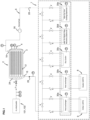
Figure 1 is a simplified block diagram of a hydrogen storage-compression system according to an embodiment of the invention; -
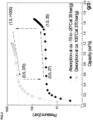
Figure 2 is a plot of pressure (in bars) versus storage capacity (in weight-percentage) of a metal hydride material of a hydrogen storage-compression system according to an embodiment of the invention; -
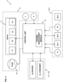
Figure 3 is a block diagram schematically illustrating a control system of a hydrogen storage-compression system according to an embodiment of the invention; -
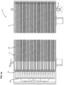
Figure 4a is a longitudinal cross-section view of a casing and storage-compression units of a hydrogen storage-compression system according to an embodiment of the invention; -
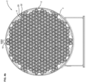
Figure 4b is a transverse cross-section view of a casing and storage-compression units of a hydrogen storage-compression system according to an embodiment of the invention. - Referring to the figures, a hydrogen storage-
compression system 1 comprises a hydrogen storage-compression apparatus 2 and athermal management system 5. - The hydrogen storage-
compression system 1 is connected to a hydrogen source 101 and a hydrogen consumer 102. The hydrogen source may for instance be an electrolyzer, a hydrogen network connected via a pipeline, a hydrogen trailer, and low- or high-pressure hydrogen cylinders. Other possibilities include hydrogen from a steam methane reforming or biomass gasification plant. The hydrogen consumer may for instance be a vehicle such as a passenger car, a truck, bus or a ship using compressed hydrogen typically stored in high pressure cylinders and utilized either in a fuel cell or combustion engine. Hydrogen may also be used in combined heat and power cycles or in other industrial processes, either as a process component (e.g. ammonia) or for high temperature heat generation (metal processing). - The hydrogen exits the metal hydrides compression during the desorption process is at a high temperature, up to 130° C. The maximum possible temperature inside the high pressure storage tanks have to follow certain requirements and safety standards during the refuelling process. The hydrogen storage-compression system according to embodiments of this invention is configured to compress hydrogen at high pressure for filling a hydrogen storage tank of the hydrogen consumer, the pressure being typically greater than 350 bar, up to over 900 bar, depending on the intended consumer application.
- The hydrogen storage-
compression apparatus 2 comprises acasing 3 and a plurality of storage-compression units 4 mounted in thecasing 3. Each storage-compression unit 4 comprises acontainer 20 and ametal hydride 22, typically in powder or granular form, provided within the container. The plurality ofcontainers 22 of the plurality of storage-compression units 4 are interconnected by a gascircuit flow system 24 comprised of gas flow tubes and valves interconnected to the hydrogen source 101 and hydrogen consumer 102 via a hydrogen inlet/outlet system through a wall of thecasing 3. Thecasing 3 sealingly surrounds and encloses the storage-compression units 4 and hydrogen inlet/outlet such that a liquid flowing through theinternal chamber 12 of the casing is sealingly contained within the casing, separated from the external environment surrounding the casing. - The
casing 3 andstorage compression units 4 may comprise a configuration that similar to the casing and storage-compressing units described inWO 2023025657 , except for the differences described herein relating inter alia to thethermal management system 5, thermal fluid, and thermal fluid circuit for cooling and heating of the storage-compression units 4 mounted within thecasing 3. - The
casing 3 surrounds the casinginternal chamber 12 within which the storage-compression units 4 are mounted, the casing comprising a thermalliquid inlet 16 on one end and one side of the casing, and a thermalliquid outlet 18 at an opposite end and opposite side of thecasing 3 such that when athermal liquid 28 flows from the thermalliquid inlet 16 to the thermalliquid outlet 18, the thermal liquid flows around the outside of thecontainers 20 of thestorage compression units 4. Thethermal liquid 28 that flows around and across the outside of thecontainers 20 serves to cool or to heat thestorage containers 4, depending on the hydrogen compression process stage and corresponding needs of the hydrogen absorption or desorption process. - Each storage-
compression container 20 preferably comprises a tubular container wall having a diameter D in a range from 1.5cm to 10cm, and wherein adjacent ones of said plurality of storage-compression containers of said at least one multi-container unit are separated by a gap G having a length in a range between 0.02xD to 1xD. - In advantageous embodiments, the diameter D of the tubular container wall of each storage-compression container is in a range from 2cm to 8cm, preferably in a range from 3cm to 6cm.
- In advantageous embodiments, the gap G between the storage-compression containers is in a range from 0.1xD to 0.5xD.
- In advantageous embodiments, the storage-compression containers have a length in a range from 60cm to 200cm, preferably in range from 80cm to 150cm.
- The above parameters allow to provide a hydrogen storage-
compression apparatus 2 with excellent heat transfer properties between the metal hydride in the storage compression units and the thermal liquid flowing through theinternal chamber 12 of thecasing 3, while providing a hydrogen storage-compression apparatus 2 with a size and configuration that makes it easily transportable by vehicles such as trucks, boats and ships, and easy to install and maintain. - The
thermal management system 5 comprises a heat exchanger system 7 and a thermalliquid circuit system 6 interconnecting the thermal liquid inlets andoutlet 16, 17 of thecasing 3 to the heat exchanger system 7. The thermalliquid circuit system 6 comprises athermal liquid pump 26 for pumping the thermal liquid through thecasing chamber 12 and heat exchanger system 7, and a plurality of valves V for controlling the flow ofthermal liquid 28 through the heat exchanger system 7. - The heat exchanger system 7 comprises at least a
first heat exchanger 30a coupled to aheating source 8, and at least asecond heat exchanger 30b coupled to acooling source 9. The heat exchanger system 7 may comprise additional heat exchangers for instance a heat exchanger forwaste heat recovery 30d and a heat exchanger forfree cooling 30e. The heat exchange system 7 may optionally further comprise adry cooler 30c. The dry cooler, also known as an air-cooled condenser or air-cooled heat exchanger, is a device used in the heat exchanger system to dissipate or absorb heat to/from the surrounding air without using water evaporation. It comprises a finned-tube heat exchanger, similar to a radiator, where the heat is exchanged between the thermal fluid and the ambient air. - In the present invention the dry cooler provides cooling or heating power during the transient phases of the heat up or cool down. In particular it allows the heat-up from the absorption temperature to the ambient temperature and the cool-down from the desorption temperature to the ambient temperature without the need of cooling or heating machine. Therefore, it allows the reduction of the overall system energy consumption.
- A plurality of valves V interconnect the thermal liquid circuit (channels, pipes) 6 to the respective heat exchangers for controlling the flow of the thermal liquid through the required heat exchanger as a function of the process stage and requirements. The
first heat exchanger 30a coupled to aheating source 8 is configured to heat the thermal liquid flow in the thermalliquid circuit system 6 to a temperature of 105° degree centigrade or higher, preferably to a temperature of up to 130° or more, and thesecond heat exchanger 30b coupled to thecooling source 9 is configured to cool thethermal liquid 28 flowing in the thermal liquid circuit system to a temperature of below at least - 20°, preferably below - 30° centigrade. - The thermal
liquid circuit system 6 is preferably configured to withstand a pressure of up to 2 bars such that thethermal liquid 28 contained within the thermalliquid circuit system 6 may circulate at up to 2 bars and remain in a liquid phase from the temperature of - 35° C to + 160° C. Preferred thermal liquid compositions are described in more detail herein below. - The
thermal management system 5 comprises acontrol system 10 comprising a control unit connected to thethermal liquid pump 26 and to the valves V, to control operation of the pump and the various valves during the hydrogen absorption and desorption processes. The control unit is further connected to the heat exchanger system 7 and to temperature sensors T, and optionally to pressure sensors P, for control of the heating and cooling processes of the thermal liquid flowing in the thermalliquid circuit 6 and through the casinginternal chamber 12. - A pressure and/or temperature sensor may be coupled to the
thermal liquid 28 in thecasing chamber 12 and additional temperature and/or pressure sensors may be positioned at different points along the thermalliquid circuit system 6. The control unit of thecontrol system 10 is further connected to the hydrogen source and consumer 101, 102 and to valves interconnecting the hydrogen storage-compression apparatus 2 to the hydrogen source and consumer 101, 102 for controlling the input and output of hydrogen between the hydrogen source and consumer 101, 102 and the storage-compression units 4 of the hydrogen storage-compression apparatus 2. - A thermal management software module is installed in the control unit to manage the control of the pump, valves and heat exchanger system as a function of the heating or cooling needs, depending on the hydrogen absorption or desorption processes and the inlet and outlet pressures between the hydrogen storage-
compression units 4 and the hydrogen source/consumer 101, 102. - The use of a thermal liquid that remains in a liquid single phase from a temperature that may range between - 30° centigrade to + 130° centigrade, typically from about - 20° centigrade to about 120° centigrade, circulating in a closed circuit that may be coupled to separate heat exchangers for cooling and heating, allows for an efficient, safe, compact and cost-effective operation of a hydrogen storage and compression system for high pressures exceeding 350 bars, up to about 900 bars. The use of heat exchangers coupled to a closed thermal liquid circuit also advantageously allows the coupling of external waste heat or free cooling devices from industrial processes that allow compression of hydrogen to be performed in an energy efficient manner.
- The basic requirement from the thermal medium is to provide sufficiently high heat transfer rate within the employed temperature range, which for the preferred material is between -30.0°C and 120°C. It is well known that a fluids is more suitable than a gas for heat transfer applications thanks to the higher thermal capacity (density, heat capacity) and increased thermal conductivity. For reasons of simplicity, phase change is also avoided. In addition, the thermal medium should have low enough viscosity such that it is suitable for usage in the system pumps and low toxicity, corrosion and oxidation potential. When a non-pressurized vessel is employed, the flash point becomes also relevant, particularly if it is within the operating temperature range of the compressor. If this is the case, proper safeguards need to be in place to guarantee that any vapor formed is safely vented to the atmosphere.
- Based on the aforementioned requirements, different thermal media can be employed. In an embodiment, a mixture of water - ethylene glycol, for instance at equal ratio (50%:50%) under 1 bar(g) pressure (or more) can be utilized as it is liquid under the given temperature and pressure range.
- In another embodiment, the thermal liquid comprises or consists of a thermal oil that can be under atmospheric conditions in an open enclosure (not a pressure vessel). An example of such a thermal medium includes Therminol D-12, Silicon Oil or FRAGOLTHERM 620 to name a few. Different grades are possible based on the required viscosity and heat transfer properties. The table below summarizes the thermal medium properties:
Thermal Media Properties Comparison Medium [-] Glycol: 50 / Water: 50 Silicon Oil Therminol D-12 Typical Quality 10 mm2/s @ 25 C 1.55 mm2/s @ 25 C Temperature [°C] -27 120 -27 120 -27 120 Density [kg/m3] 1'133 1'054 942 614 798 687 Heat Capacity [J/kg-k] 3'185 3'550 1'430 1'587 1'900 2'500 Density x Heat Capacity [MJ/m3-k] 3.60 3.74 1.34 0.97 1.51 1.71 Viscosity [mm2/s] 38.6 4.1 34.3 2.16 5.76 0.55 Flash Point [°C] 110 120 62 - In an advantageous embodiment, the metal hydrides contained in the storage-
compression units 4 are of the material class AB2 with a typical composition of TixZryCraMnbFecNidCueVf, in which x, y, a, b, c and d are molar ratios Re is selected from La and Ce; 0.2 ≤ x ≤ 0.95; 0.05 ≤ y ≤ 0.45; 0.001 ≤ a ≤ 1; 0.3 ≤ b ≤2; 0.01 ≤ c ≤0.6; 0.005 ≤ d ≤ 1.5; 0 ≤ e ≤ 0.1; 0 ≤ f ≤ 0.5; a+b+c+d+e+f= 1.9-2.1. - In another embodiment, the metal hydrides contained in the storage-
compression units 4 are of the material class AB5 with a typical composition of LaxCeyMI(1-x-y)Nia CobFecMd, in which x, y, a, b, c and d are molar ratios, where Ml is at least one element selected from Y, Ti, Zr and M is selected from Cu and Mn; 0.15 ≤ x ≤ 0.95; 0.05 ≤ y ≤ 0.85; 0 ≤ (1-x-y) ≤ 0.1; 3.8 ≤ a ≤ 4.2; 0.1 ≤ b ≤1.2; 0.01 ≤ c ≤0.3; 0 ≤ d ≤ 0.1; 4.8 ≤ (a+b+c+d) ≤ 5.15. - Within the scope of the invention, hydrogen storage metals are not limited to AB2 or AB5 materials, but can also be applied to materials of other classes showing similar thermo-chemical behaviors.
- The hydrogen storage-compression system operating in a full cycle may include the following phases in the presented order: (i) absorption (ii) heat-up (iii) desorption (iv) cool-down. An example of these processes are described in more detail below. The values indicated correspond to an embodiment with a thermal liquid consisting of water - ethylene glycol mixture at equal ratio (50%:50%) under 1 bar(g) pressure.
- Hydrogen is absorbed into the storage-
compression units 4 at a nearly isobaric process from an external source. The pressure of the Hz source typically ranges from 25 bar(g) to 40 bar(g) and most commonly is 35 bar(g) for a typical electrolyzer. Since the absorption reaction is highly exothermic (results in release of heat), the storage-compression units 4 need to be cooled to maintain the developed pressure below the charging one. The cooling power provided needs to also compensate for the inevitable heat-up by the ambient, which also tends to increase the developed storage-compression unit hydrogen pressure. This energy requirement is mainly a function of the metal hydride material absorption enthalpy, which is 18.0 kJ/molH2 for the preferred material, resulting in an energy requirement of 87 kWhth or around 2.7 kWhth/kgH2 (both values include the heat-up compensation energy). - The absorption process time requirement depends on the type of Hz source and can range from 1 to 8 hours, with a resulting cooling power of 10.9 kWth to 87 kWth. For a preferred metal hydride material, the inlet fluid temperature to the compressor is generally between -30°C to -0°C, with a typical value of -25.0°C to -20°C. The typical cooling flow rate is 7.5 m3/h. The thermal liquid flows through the
cooling heat exchanger 30a and by-passes thedry cooler 30c andheating heat exchanger 30b. It should be mentioned that the inlet temperature is lower than the temperature of the material PCT curve corresponding to the absorption pressure as the exothermic reaction generates an inverse-parabolic temperature profile within the metal hydride.Absorption Hydrogen storage-compression apparatus batch capacity (kgH2) 28 28 28 28 28 Duration (min) 6 10 20 39 155 H2 Flow Rate (kgH2/h) 262 175 86 43 11 Thermal Power (kWth) 739 493 243 122 31 TTF,in -25 -25 -25 -25 -25 TTF,out -22 -22 -22 -22 -22 TF Flow Rate (1000-kg/h); Water - Glycol (50%/50%) 268 179 88 44 11 TF Flow Rate (1000·kg/h); Therminol 350 233 114 57 14 - During the desorption process, hydrogen is released from the hydrogen storage-
compression apparatus 2 to a hydrogen consumer 102 such as a hydrogen-powered vehicle such as a truck or a bus, which requires refueling at 350 bar or more. The desorption pressure can be adjusted through the material and the thermal medium temperature selection. The vehicle refueling time required dictates the desorption rate of hydrogen. The refueling time can be in the order of few minutes e.g., 5-15 min up to several hours e.g., 3 - 8 h. The storage-compression unit 4 desorption pressure is a function of the final mass to be delivered, the desorption mass flow rate and the temperature of hydrogen before entering the hydrogen-powered vehicle. As an example, for an application such as slow refueling at 6 kgH2/h, which results in 05 h:20 min refueling time for a Hyundai Xcient track (32 kgHz), and hydrogen temperature - 25.0°C after the hydrogen cooler, the desorption pressure is 370 bar. This case is advantageous as the cooling source of the metal hydrides compressor thermal management system, can be directly utilized for the hydrogen cooling. Other flow rates are also possible at the expense of increasing the desorption pressure and/or further reducing the hydrogen temperature. - Maintaining a thermal liquid flow rate of 7.5 m3/h as in the case of absorption, results in a required inlet temperature of 110°C to achieve a desorption pressure of 370 bar for the given material. The total energy requirement to compensate the cooling effect of the desorption and counter-balance the heat losses to ambient is 110.8 kWhth or around 3.5 kWhth/kgH2 based on a desorption enthalpy of 20.0 kJ/molH2. During this phase, the thermal liquid flows through the
heating heat exhanger 30b and bypasses thedry cooler 30c and thecooling heat exhanger 30a. Given the time duration of the desorption and the energy requirement of this phase, the power to be delivered by the heating machine is 20.8 kWth.Desorption Hydrogen storage-compression apparatus batch capacity (kgH2) 28 28 28 28 28 Duration (min) 5 8 15 29 116 H2 Flow Rate (kgH2/h) 336 224 116 58 15 Thermal Power (kWth) 1196 798 413 206 52 TTF,in 110 110 110 110 110 TTF,out 107 107 107 107 107 TF Flow Rate (1000-kg/h); Water - Glycol (50%/50%) 435 290 150 75 19 TF Flow Rate (1000·kg/h); Therminol 756 504 261 130 33 - Once the absorption process is completed, the storage-
compression units 4 are heated up from the absorption (-25.0°C) to the desorption temperature (110°C), due to the thermal liquid that flows initially through thedry cooler 30c and finally through theheating heat exhanger 30b. The heat-up is accompanied by increase of the storage-compression units 4 internal pressure to 370 bar. During the initial phase of the heat-up, the flow through thedry cooler 30c allows the temperature of the storage-compression units 4 to increase from the absorption temperature to the ambient one. This energy is essentially provided for free; it requires, however, a certain pumping power for the liquid flow through thedry cooler 30c. The total heat-up energy required is 5.4 kWhth/kgH2(172.8 kWhth) out of which 1.7 kWhth/kgH2(55.1 kWhth) is provided by thedry cooler 30c while the remaining energy 3.6 kWhth/kgH2 (117.2 kWhth) from theheating heat exhanger 30b. During the heat-up process the flow rate is 7.5 m3/h. To simplify the system, it is assumed that the sameheating heat exhanger 30b is used as for the desorption. If the same electrical energy is provided to theheating heat exhanger 30b, the thermal power is varying and dependent on the coefficient of performance over this temperature range. The heat-up phase time duration is approximately 05 h:20 min.Heat-Up Hydrogen storage-compression apparatus batch capacity (kgH2) 28 28 28 28 28 Duration (min) 5 8 15 31 124 H2 Flow Rate (kgH2/h) 0 0 0 0 0 Thermal Power (kwth) 1196 798 413 206 52 TTF,in Varying = = = = TTF,out Varying = = = = TF Flow Rate (1000·kg/h); Water - Glycol (50%/50%) 435 290 150 75 19 TF Flow Rate (1000·kg/h); Therminol 756 504 261 130 33 - Following the end of the desorption the storage-
compression units 4 are cooled-down from the desorption (110.0°C) to the absorption temperature (-25.0°C). Similarly to the heat-up, initially all or most flow is directed through the dry cooler 30c to make use of the freely available ambient cooling. When the ambient temperature is reached, the flow is directed through thecooling heat exhanger 30a to achieve the subcooling to the absorption temperature. The total cool-down energy required is 4.7 kWhth/kgH2(149.2 kWhth) out of which 3.2 kWhth/kgH2(101.5 kWhth) is provided by thedry cooler 30c while the remaining energy 1.5 kWhth/kgH2(47.7 kWhth) from thecooling heat exchanger 30a. During the cool-down process, the flow rate is 7.5 m3/h. - The same cooling heat exchanger is used for the cool-down, resulting in a phase duration of 02 h:11 min.
Cool-Down Hydrogen storage-compression apparatus batch capacity (kgH2) 28 28 28 28 28 Duration (min) 4 5 11 21 85 H2 Flow Rate (kgH2/h) 0 0 0 0 0 Thermal Power (kWth) 739 493 243 122 31 TTF,in Varying = = = = TTF,out Varying = = = = TF Flow Rate (1000·kg/h); Water - Glycol (50%/50%) 268 179 88 44 11 TF Flow Rate (1000·kg/h); Therminol 350 233 114 57 14 - In an application, the hydrogen storage-compression system may advantageously be used as a system to refuel hydrogen-powered vehicles such a trucks or buses which require a refuelling level of 350 bar. In such application, the outlet pressure is typically ramped up to slightly exceed the pressure of the tanks to be refuelled (e.g., by 10 bar) by selectively adapting the heating power. In such application, the typical desorption time can be as low as 5 or 15 minutes. In other cases, the desorption time can be 60 minutes or even 180 minutes or longer. In such application, the typical inlet pressure ranges from 25 bar(g) to 35 bar(g). The typical cooling temperature ranges from -15°C to -30°C. The typical heating temperature ranges from 90°C to 130°C.
- In another application, the hydrogen storage-compression system may advantageously be used as a system to refuel hydrogen-powered vehicles such a heavy-duty or light vehicles which require a refuelling level of 700 bar. In such applications, the outlet pressure is typically ramped up to slightly exceed the pressure of the tanks to be refuelled (e.g., by 10 bar) by selectively adapting the heating power. In such application, the typical desorption time can be as low as 5 or 15 minutes. In other cases, the desorption time can be 60 minutes or even 180 minutes or longer. In such application, the typical inlet pressure ranges from 150 bar(g) to 350 bar(g). The typical cooling temperature ranges from 5°C to -30°C. The typical heating temperature ranges from 60°C to 130°C.
- In another application, the hydrogen storage-compression system may advantageously be used as a system to refuel trailers for the transport or storage of hydrogen, which require a refuelling level of 200 bar. In such applications, the outlet pressure is typically ramped up to slightly exceed the pressure of the tanks to be refuelled (e.g., by 10 bar) by selectively adapting the heating power. In such application, the typical desorption time can be as low as 60 minutes. In other cases, the desorption time can be 180 minutes or even 300 minutes or longer. In such application, the typical inlet pressure ranges from 25 bar(g) to 35 bar(g). The typical cooling temperature ranges from -15°C to -30°C. The typical heating temperature ranges from 90°C to 130°C.
-
- Hydrogen source 101
- Hydrogen consumer 102
-
Hydrogen storage-
compression system 1-
Hydrogen storage-
compression apparatus 2-
Casing 3- Casing
internal chamber 12 - Hydrogen Inlet /outlet 14
- Thermal
liquid inlet 16 - Thermal
liquid outlet 18
- Casing
-
Storage-
compression units 4-
Containers 20 -
Metal hydride 22 - Gas
circuit flow system 24
-
-
-
Thermal management system 5-
Thermal
liquid circuit system 6- Thermal
liquid pump 26 -
Thermal liquid 28
- Thermal
-
Heating exchanger system 7
-
First heat exchanger 30a -
Second heat exchanger 30b
-
-
Heating source 8 -
Cooling
source 9 -
Control system 10- Pressure sensors P
- Temperature sensors T
- Valves V
-
Thermal
-
Hydrogen storage-
- Storage-compression container diameter D
- Gap distance between adjacent containers G
- Length of a container L
Claims (14)
- Hydrogen storage-compression system (1) comprising a hydrogen storage-compression apparatus (2) and a thermal management system (5), the hydrogen storage-compression apparatus comprising a casing (3) and a plurality of storage-compression units (4) mounted within an internal chamber (12) of the casing, each storage-compression unit comprising a container (20) and a metal hydride (MH) configured for hydrogen storage-compression contained within the container, the plurality of storage-compression containers interconnected by a hydrogen gas circuit flow system (24) to a hydrogen inlet and outlet (16) for connection to a hydrogen consumer (102) and a hydrogen source (101), characterized in that the thermal management system (5) comprises a thermal liquid circuit system (6) and a heat exchanger system (7) the thermal liquid circuit system (6) comprising:- a closed loop thermal liquid flow circuit,- a thermal liquid (28) contained and flowing within a thermal liquid flow circuit, and- a thermal liquid pump for pumping the thermal liquid in the thermal liquid flow circuit,the thermal liquid flow circuit connected to a thermal liquid inlet (16) and a thermal liquid outlet (18) of the casing (3) for flowing thermal liquid (28) through casing internal chamber (12) around the containers (20) of the storage-compression units (4) for cooling or heating thereof,the thermal liquid flow circuit coupled to at least a first heat exchanger (30a) thermally coupled to heating source (8) and a second heat exchanger (30b) thermally coupled to a cooling source (9),the system further comprising a control system (10) connected to the thermal liquid circuit system for controlling the flow of the thermal liquid in the circuit and through the heat exchangers.
- The hydrogen storage-compression system of the preceding claim wherein the thermal management system comprises a dry cooler (30c) thermally coupled to the thermal liquid flow circuit.
- The hydrogen storage-compression system of any preceding claim wherein the thermal management system comprises additional heat exchangers (30b, 30d) thermally coupled to the thermal liquid flow circuit, for instance a heat exchanger for waste heat recovery thermally coupled to an industrial process output, and / or a heat exchanger for free cooling.
- The hydrogen storage-compression system according to any of the preceding claims wherein the thermal liquid (28) is selected from any one or more of a water - ethylene glycol mixture, a silicon oil, a synthetic hydrocarbon oil.
- The hydrogen storage-compression system according to any of the preceding claims wherein the thermal liquid (28) comprises principally or consists of a water - ethylene glycol mixture in a proportion water to ethylene glycol in a range from 45%-55% to 55%-45%, preferably about 50%-50%.
- The hydrogen storage-compression system of any preceding claim wherein the metal hydride contained in the storage-compression units are of the material class AB2 with a typical composition of TixZryCraMnbFecNidCueVf, in which x, y, a, b, c and d are molar ratios Re is selected from La and Ce; 0.2 ≤ x ≤ 0.95; 0.05 ≤ y ≤ 0.45; 0.001 ≤ a ≤ 1; 0.3 ≤ b ≤2; 0.01 ≤ c ≤0.6; 0.005 ≤ d ≤ 1.5; 0 ≤ e ≤ 0.1; 0 ≤ f ≤ 0.5; a+b+c+d+e+f= 1.9-2.1.
- The hydrogen storage-compression system of any preceding claim 1-4 wherein the metal hydrides contained in the storage-compression units are of the material class AB5 with a typical composition of LaxCeyMI(1-x-y)Nia CobFecMd, in which x, y, a, b, c and d are molar ratios, where Ml is at least one element selected from Y, Ti, Zr and M is selected from Cu and Mn; 0.15 ≤ x ≤ 0.95; 0.05 ≤ y ≤ 0.85; 0 ≤ (1-x-y) ≤ 0.1; 3.8 ≤ a ≤ 4.2; 0.1 ≤ b ≤1.2; 0.01 ≤ c ≤0.3; 0 ≤ d ≤ 0.1; 4.8 ≤ (a+b+c+d) ≤ 5.15.
- The hydrogen storage-compression system according to any of the preceding claims wherein the casing (3) and thermal liquid flow circuit (6) is configured to withstand an internal pressure of at least 2 bars.
- The hydrogen storage-compression system according to any of the preceding claims wherein the control system (10) is connected to valves of the hydrogen gas circuit flow system (24) and to pressure sensors and temperature sensors connected to the hydrogen gas circuit flow system (24) to control the inflow and outflow of hydrogen from the hydrogen storage compression system to and from the hydrogen source and hydrogen consumer.
- Hydrogen storage-compression system according to any preceding claim wherein each storage-compression container (20) comprises a tubular container wall having a diameter D in a range from 1.5cm to 10cm, and wherein adjacent ones of said plurality of storage-compression containers of said at least one multi-container unit are separated by a gap (G) having a length in a range between 0.02xD to 1xD.
- Hydrogen storage-compression system according to the preceding claim wherein the diameter D of the tubular container wall of each storage-compression container is in a range from 2cm to 8cm, preferably in a range from 3cm to 6cm.
- Hydrogen storage-compression system according to either of the two directly preceding claims wherein the gap (G) between the storage-compression containers is in a range from O.lxD to 0.5xD.
- Hydrogen storage-compression system according to any of the three directly preceding claims wherein the storage-compression containers have a length in a range from 60cm to 200cm, preferably in range from 80cm to 150cm.
- Hydrogen storage-compression system according to any preceding claim used as a near-isobaric hydrogen supply system to absorb and desorb hydrogen at elevated pressure, preferably greater than 50 bar, more preferably greater than 200 bar, and desorb it at substantially constant pressure with a minimal change in temperature, preferably with a temperature change less than 40°C, more preferably with a temperature change ranging from 20°C to 30°C.
Priority Applications (5)
| Application Number | Priority Date | Filing Date | Title |
|---|---|---|---|
| EP23189911.3A EP4506302A1 (en) | 2023-08-07 | 2023-08-07 | Hydrogen storage and compression system |
| US18/598,829 US12372205B2 (en) | 2023-08-07 | 2024-03-07 | Hydrogen storage and compression system |
| CN202411058474.1A CN119435973A (en) | 2023-08-07 | 2024-08-02 | Hydrogen storage and compression systems |
| JP2024130029A JP2025024696A (en) | 2023-08-07 | 2024-08-06 | Hydrogen Storage and Compression Systems |
| KR1020240105432A KR20250022636A (en) | 2023-08-07 | 2024-08-07 | Hydrogen storage and compression system |
Applications Claiming Priority (1)
| Application Number | Priority Date | Filing Date | Title |
|---|---|---|---|
| EP23189911.3A EP4506302A1 (en) | 2023-08-07 | 2023-08-07 | Hydrogen storage and compression system |
Publications (1)
| Publication Number | Publication Date |
|---|---|
| EP4506302A1 true EP4506302A1 (en) | 2025-02-12 |
Family
ID=87557528
Family Applications (1)
| Application Number | Title | Priority Date | Filing Date |
|---|---|---|---|
| EP23189911.3A Pending EP4506302A1 (en) | 2023-08-07 | 2023-08-07 | Hydrogen storage and compression system |
Country Status (5)
| Country | Link |
|---|---|
| US (1) | US12372205B2 (en) |
| EP (1) | EP4506302A1 (en) |
| JP (1) | JP2025024696A (en) |
| KR (1) | KR20250022636A (en) |
| CN (1) | CN119435973A (en) |
Citations (5)
| Publication number | Priority date | Publication date | Assignee | Title |
|---|---|---|---|---|
| US4436539A (en) * | 1981-10-06 | 1984-03-13 | Technion Research And Development Foundation Ltd. | Method and apparatus for air-conditioning by means of a hydrogen heat pump |
| US5862855A (en) * | 1996-01-04 | 1999-01-26 | Balk; Sheldon | Hydride bed and heat pump |
| US20170198947A1 (en) * | 2016-01-11 | 2017-07-13 | Xergy Inc. | Advanced Metal Hydride Heat Transfer System Utilizing An Electrochemical Hydrogen Compressor |
| US20190093825A1 (en) * | 2017-09-26 | 2019-03-28 | Hystorsys AS | Hydrogen storage and release arrangement |
| EP4141315A1 (en) * | 2021-08-23 | 2023-03-01 | GRZ Technologies SA | Hydrogen storage-compression system |
Family Cites Families (1)
| Publication number | Priority date | Publication date | Assignee | Title |
|---|---|---|---|---|
| US5469913A (en) * | 1992-12-18 | 1995-11-28 | Matsushita Electric Industrial Co., Ltd. | Vehicle using hydrogen absorbing alloys |
-
2023
- 2023-08-07 EP EP23189911.3A patent/EP4506302A1/en active Pending
-
2024
- 2024-03-07 US US18/598,829 patent/US12372205B2/en active Active
- 2024-08-02 CN CN202411058474.1A patent/CN119435973A/en active Pending
- 2024-08-06 JP JP2024130029A patent/JP2025024696A/en active Pending
- 2024-08-07 KR KR1020240105432A patent/KR20250022636A/en active Pending
Patent Citations (6)
| Publication number | Priority date | Publication date | Assignee | Title |
|---|---|---|---|---|
| US4436539A (en) * | 1981-10-06 | 1984-03-13 | Technion Research And Development Foundation Ltd. | Method and apparatus for air-conditioning by means of a hydrogen heat pump |
| US5862855A (en) * | 1996-01-04 | 1999-01-26 | Balk; Sheldon | Hydride bed and heat pump |
| US20170198947A1 (en) * | 2016-01-11 | 2017-07-13 | Xergy Inc. | Advanced Metal Hydride Heat Transfer System Utilizing An Electrochemical Hydrogen Compressor |
| US20190093825A1 (en) * | 2017-09-26 | 2019-03-28 | Hystorsys AS | Hydrogen storage and release arrangement |
| EP4141315A1 (en) * | 2021-08-23 | 2023-03-01 | GRZ Technologies SA | Hydrogen storage-compression system |
| WO2023025657A1 (en) | 2021-08-23 | 2023-03-02 | Grz Technologies Sa | Hydrogen storage-compression system |
Also Published As
| Publication number | Publication date |
|---|---|
| KR20250022636A (en) | 2025-02-17 |
| JP2025024696A (en) | 2025-02-20 |
| US20250052374A1 (en) | 2025-02-13 |
| US12372205B2 (en) | 2025-07-29 |
| CN119435973A (en) | 2025-02-14 |
Similar Documents
| Publication | Publication Date | Title |
|---|---|---|
| Lototskyy et al. | Metal hydride hydrogen storage tank for fuel cell utility vehicles | |
| US6860923B2 (en) | Onboard hydrogen storage unit with heat transfer system for use in a hydrogen powered vehicle | |
| US7891386B2 (en) | Thermal management for high pressure storage tanks | |
| US7036324B2 (en) | Hydrogen storage and supply system | |
| Bogdanović et al. | A process steam generator based on the high temperature magnesium hydride/magnesium heat storage system | |
| EP2147242B1 (en) | High pressure gas tank heat management by circulation of the refueling gas | |
| US12104751B2 (en) | Combined hydrogen storage - compression system for the filling of high pressure hydrogen tanks | |
| JP2009510352A (en) | Method and device for filling a tank with pressurized gas | |
| CN101459249A (en) | Hydrogen storage system for fuel cell vehicle | |
| CN101128952A (en) | Method for using hydrogen storage tank and hydrogen storage tank | |
| KR102902313B1 (en) | Hydrogen storage compression system | |
| WO2017040550A1 (en) | Gas fueling systems and methods with minimum and/or no cooling | |
| US4436539A (en) | Method and apparatus for air-conditioning by means of a hydrogen heat pump | |
| Ahluwalia et al. | Bounding material properties for automotive storage of hydrogen in metal hydrides for low-temperature fuel cells | |
| Wimmer et al. | High performance reactor of a metal hydride based cooling system for air-conditioning of fuel cell electric vehicles | |
| US12372205B2 (en) | Hydrogen storage and compression system | |
| US20230279996A1 (en) | Method and System for Forming and Dispensing a Compressed Gas | |
| Petitpas et al. | Hydrogen storage in pressure vessels: liquid, cryogenic, and compressed gas | |
| KR102950432B1 (en) | Integrated thermal management system of liquid ammonia based powerpack | |
| EP1634016B1 (en) | Storage of h2 by absorption in liquid nitrogen | |
| EP1828592A1 (en) | Fuel supply device for a motor vehicle that can be operated by hydrogen | |
| WO2026093161A1 (en) | Hydrogen fueling system | |
| Lutz et al. | Electricity storage based on coupled thermochemical reactions: The Thermochemical Battery | |
| US20250305493A1 (en) | Gas compression system and method for recovering hydrogen | |
| Schwarz | Department of Chemical Engineering and Materials Science and. Laboratory for Advanced Storage Systems for Hydrogen Syracuse University |
Legal Events
| Date | Code | Title | Description |
|---|---|---|---|
| PUAI | Public reference made under article 153(3) epc to a published international application that has entered the european phase |
Free format text: ORIGINAL CODE: 0009012 |
|
| STAA | Information on the status of an ep patent application or granted ep patent |
Free format text: STATUS: THE APPLICATION HAS BEEN PUBLISHED |
|
| AK | Designated contracting states |
Kind code of ref document: A1 Designated state(s): AL AT BE BG CH CY CZ DE DK EE ES FI FR GB GR HR HU IE IS IT LI LT LU LV MC ME MK MT NL NO PL PT RO RS SE SI SK SM TR |
|
| P01 | Opt-out of the competence of the unified patent court (upc) registered |
Free format text: CASE NUMBER: APP_13843/2025 Effective date: 20250320 |
|
| STAA | Information on the status of an ep patent application or granted ep patent |
Free format text: STATUS: REQUEST FOR EXAMINATION WAS MADE |
|
| 17P | Request for examination filed |
Effective date: 20250811 |